YASKAWA E-V Series User Manual
Ac servodrive, linear motor, communications reference
Hide thumbs
Also See for E-V Series:
- User manual (435 pages) ,
- User manual (223 pages) ,
- User manual (55 pages)
Table of Contents
Advertisement
Quick Links
AC Servodrive
Σ - V Series
USER'S MANUAL
Design and Maintenance
Linear Motor
MECHATROLINK-
SGDV SERVOPACK
SGLGW/SGLFW/SGLTW/SGLCW/SGT Linear Servomotors
MANUAL NO. SIEP S800000 48B
II
Communications Reference
Operation of Digital Operator
Utility Functions (Fn)
Outline
Panel Display and
Wiring and Connection
Operation
Adjustments
Monitor Modes (Un)
Troubleshooting
Appendix
1
2
3
4
5
6
7
8
9
Advertisement
Table of Contents
Troubleshooting

Related Manuals for YASKAWA E-V Series


Summary of Contents for YASKAWA E-V Series
- Page 1 AC Servodrive Σ - V Series USER'S MANUAL Design and Maintenance Linear Motor MECHATROLINK- Communications Reference SGDV SERVOPACK SGLGW/SGLFW/SGLTW/SGLCW/SGT Linear Servomotors Outline Panel Display and Operation of Digital Operator Wiring and Connection Operation Adjustments Utility Functions (Fn) Monitor Modes (Un) Troubleshooting Appendix MANUAL NO.
- Page 2 Yaskawa. No patent liability is assumed with respect to the use of the information contained herein. Moreover, because Yaskawa is con- stantly striving to improve its high-quality products, the information contained in this manual is subject to change without notice.
-
Page 3: About This Manual
About this Manual This manual describes informations required for designing, and maintaining Σ-V Series SERVOPACKs. Be sure to refer to this manual and perform design and maintenance to select devices correctly. Keep this manual in a location where it can be accessed for reference whenever required. Description of Technical Terms The following table shows the meanings of terms used in this manual. - Page 4 Manuals Related to the Σ-V Series Refer to the following manuals as required. Selecting Trial Maintenance Models and Ratings and System Panels and Trial Operation Name Peripheral Specifications Design Wiring Operation and Servo Inspection Devices Adjustment Σ-V Series User's Manual Setup Linear Motor (SIEPS80000044)
- Page 5 Safety Information The following conventions are used to indicate precautions in this manual. Failure to heed precautions pro- vided in this manual can result in serious or possibly even fatal injury or damage to the products or to related equipment and systems. Indicates precautions that, if not heeded, could possibly result in loss of WARNING life or serious injury.
-
Page 6: Safety Precautions
Safety Precautions These safety precautions are very important. Read them before performing any procedures such as checking products on delivery, storage and transportation, installation, wiring, operation and inspection, or disposal. Be sure to always observe these precautions thoroughly. WARNING • If you have a pacemaker or any other electronic medical device, do not go near the magnetic way of the linear servomotor. - Page 7 Storage and Transportation CAUTION • Be sure to store the magnetic way in the package that was used for delivery. • Do not store or install the product in the following locations. Failure to observe this caution may result in fire, electric shock, or damage to the product. •...
- Page 8 Installation CAUTION • When unpacking and installing magnetic way, check that no metal fragments or magnetized objects near the magnetic because they may be affected by the magnetic attraction of the magnetic way. Failure to observe this caution may result in injury or damage to the magnetic way's magnets. •...
- Page 9 Wiring CAUTION • Securely tighten the cable connector screws and securing mechanism. If the connector screws and securing mechanism are not secure, they may loosen during operation. • Use cables with a radius, heat resistance, and flexibility suitable for the system. •...
- Page 10 Operation CAUTION • Always use the linear servomotor and SERVOPACK in one of the specified combinations. Failure to observe this caution may result in fire or malfunction. • Do not stand within the machine's range of motion during operation. Failure to observe this caution may result in injury. •...
- Page 11 When this manual is revised, the manual code is updated and the new manual is published as a next edition. The edition number appears on the front and back covers. • If the manual must be ordered due to loss or damage, inform your nearest Yaskawa representative or one of the offices listed on the back of this manual.
-
Page 12: Applicable Standards
Applicable Standards North American Safety Standards (UL) ∗ Standards Model (UL File No.) SERVOPACK • SGDV UL508C (E147823) ∗ Underwriters Laboratories Inc. European Standards EMC Directive Low Voltage Safety Model Directive Standards EN50178 EN55011 SERVOPACK • SGDV EN61800-3 EN954 class A group 1 EN61800-5-1 Note: Because SERVOPACKs and servomotors are built into machines, certification is required after installation in the final product. -
Page 13: Table Of Contents
Contents About this Manual ............iii Safety Precautions. - Page 14 3.2.5 Example of I/O Signal Connections ......... 3-20 3.3 I/O Signal Allocation .
- Page 15 5.3 Advanced Autotuning (Fn201) ........5-14 5.3.1 Advanced Autotuning .
- Page 16 Chapter 7 Monitor Modes (Un ) ......7-1 7.1 List of Monitor Modes ......... . . 7-2 7.2 Monitor Mode Display.
- Page 17 Outline 1.1 Σ-V Series SERVOPACKs ........1-2 1.2 Part Names .
-
Page 18: Σ-V Series Servopacks
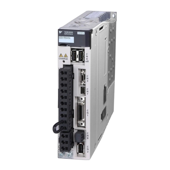
1 Outline Σ-V Series SERVOPACKs The Σ-V Series SERVOPACKs are designed for applications that require frequent high-speed, high-pre- cision positioning. The SERVOPACK makes the most of machine performance in the shortest time possi- ble, thus contributing to improving productivity. Part Names This section describes the part names of SGDV type SERVOPACK for MECHATROLINK-II communica- tions reference. -
Page 19: Servopack Ratings And Specifications
1.3 SERVOPACK Ratings and Specifications SERVOPACK Ratings and Specifications This section describes the ratings and specifications of SERVOPACKs. 1.3.1 Ratings Ratings of SERVOPACKs are as shown below. (1) 100 VAC Rating SGDV (100 VAC) Continuous Output Current 0.66 0.91 [Arms] Max. -
Page 20: Basic Specifications
1 Outline 1.3.2 Basic Specifications 1.3.2 Basic Specifications Basic specifications of SERVOPACKs are shown below. Single or three-phase full-wave rectification IGBT-PWM (sine-wave Control Method driven) Feedback 1/256 data of serial converter unit sine wave pitch (incremental) Surrounding Air/Storage 0 to +55°C/ -20 to +85°C Temperature Surrounding Air/Storage 90% RH or less (with no condensation) - Page 21 1.3 SERVOPACK Ratings and Specifications Digital operator (JUSP-OP05A-1-E), personal computer (can be connected Interface with SigmaWin+), etc. RS422A Communi- Communica- N = Up to 15 stations possible at RS422A cations tions Communi- (CN3) cations Axis Address Set by parameter Function Setting Interface Personal computer (can be connected with SigmaWin+.)
-
Page 22: Mechatrolink-Ii Function Specifications
1 Outline 1.3.3 MECHATROLINK-II Function Specifications 1.3.3 MECHATROLINK-II Function Specifications The following table shows the basic specifications of MECHATROLINK-II. Function Specifications Communication MECHATROLINK-II Protocol Station Address 41H to 5FH (Max. number of stations: 30) MECHATROLINK-II Baud Rate 10 Mbps,4 Mbps Communication Transmission Cycle 250 μs,0.5 ms to 4.0 ms (Multiples of 0.5 ms) -
Page 23: Examples Of Servo System Configurations
1.4 Examples of Servo System Configurations Examples of Servo System Configurations This section describes examples of basic servo system configuration. 1.4.1 Connecting to SGDV- F15A SERVOPACK Power supply Single-phase 100 VAC Molded-case circuit breaker (MCCB) Protects the power supply line by shutting the circuit OFF when overcurrent is detected. -
Page 24: A15A Servopack
1 Outline 1.4.2 Connecting to SGDV- A15A SERVOPACK 1.4.2 Connecting to SGDV- A15A SERVOPACK Power supply Three-phase 200 VAC R S T Molded-case circuit breaker (MCCB) Protects the power supply line by shutting the circuit OFF when Connect to the overcurrent is detected. -
Page 25: D15A Servopack
1.4 Examples of Servo System Configurations 1.4.3 Connecting to SGDV- D15A SERVOPACK Power supply Three-phase 400 VAC R S T Molded-case circuit breaker (MCCB) Protects the power supply line by shutting the circuit OFF when overcurrent is detected. Connect to the MECHATROLINK-II Noise filter Used to eliminate Digital... -
Page 26: Servopack Model Designation
1 Outline SERVOPACK Model Designation Select the SERVOPACK according to the applied servomotor. 8th to13th digits 1st + 2nd + 5th + 6th digit digit 3rd digits digits SGDV – 2R8 A 11 A Series 7th digit: Design Revision Order Σ-V Series SGDV 8th to 13th digits: Option... -
Page 27: Inspection And Maintenance
Refer to the standard replacement period in the following table, contact your Yaskawa representative. After an examination of the part in question, we will determine whether the parts should be replaced or not. - Page 28 Panel Display and Operation of Digital Operator 2.1 Panel Display ..........2-2 2.1.1 Status Display .
-
Page 29: Chapter 2 Panel Display And Operation Of Digital Operator
2 Panel Display and Operation of Digital Operator 2.1.1 Status Display Panel Display The servo status can be checked on the panel display of the SERVOPACK. Also, if an alarm or warning occurs, its alarm or warning number is displayed. 2.1.1 Status Display The display shows the following status. -
Page 30: Monitor Mode (Un )
2.2 Utility Function Mode (Fn ), Parameter Setting Mode (Pn ), Monitor Mode (Un Utility Function Mode (Fn ), Parameter Setting Mode ), Monitor Mode (Un Operation examples of Utility Function Mode (Fn ), Parameter Setting Mode (Pn ) and Monitor Mode (Un ) are in the following table. - Page 31 2 Panel Display and Operation of Digital Operator Display on the Digital Step Keys Description Operator Press the Key. The display returns to the Utility Function Mode main menu. This completes the operation.
-
Page 32: How To Read A Parameter Explanation
2.4 How to Read a Parameter Explanation How to Read a Parameter Explanation In this manual, each parameter is explained using the following example. 2.4.1 Explanation Method for Parameter Setting Type Control mode for which the parameter is available : Speed control and Speed internally set speed control Position... -
Page 33: Parameter Setting Mode (Pn )
2 Panel Display and Operation of Digital Operator 2.5.1 Parameter Setting Mode for Parameter Setting Type Parameter Setting Mode (Pn Parameters related to the SERVOPACK are set in this mode. The digital operator displays numbers beginning with Pn. There are two types of parameters. One type requires value setting (parameter setting type) and the other requires selecting the function allocated to each digit (function selection type). - Page 34 2.5 Parameter Setting Mode (Pn Display on the Digital Step Keys Description Operator Press the Key to write the settings.
-
Page 35: Parameter Setting Mode For Function Selection Type
2 Panel Display and Operation of Digital Operator 2.5.2 Parameter Setting Mode for Function Selection Type 2.5.2 Parameter Setting Mode for Function Selection Type The following example shows how to set the clear signal form (Pn200.1) of the position control reference form selection switch (Pn200) to 0 "clearing position error pulse if the signal is at H level."... -
Page 36: Monitor Mode (Un )
2.6 Monitor Mode (Un Monitor Mode (Un The monitor mode can be used for monitoring the reference values, I/O signal status, and SERVOPACK inter- nal status. For details, refer to 7.2 Monitor Mode Display The digital operator display numbers beginning with Un. The following four settings are the factory settings. - Page 37 Wiring and Connection 3.1 Main Circuit Wiring ......... . 3-2 3.1.1 Names and Functions of Main Circuit Terminals .
-
Page 38: Chapter 3 Wiring And Connection
3 Wiring and Connection Main Circuit Wiring The names, specifications, and functions of the main circuit terminals are given on the following page. Also this section describes the general precautions for wiring and precautions under special environments. -
Page 39: Names And Functions Of Main Circuit Terminals
3.1 Main Circuit Wiring 3.1.1 Names and Functions of Main Circuit Terminals Names, functions and specifications are shown in the following table. : Main terminals Name Terminal Symbols Model SGDV- Description Single-phase 100 to 115 V, L1, L2 +10% to -15% (50/60 Hz) Main circuit input Three-phase 200 to 230 V, terminals... -
Page 40: Servopack Main Circuit Wire Size
3 Wiring and Connection 3.1.2 SERVOPACK Main Circuit Wire Size 3.1.2 SERVOPACK Main Circuit Wire Size This section describes the SERVOPACK Main Circuit Wire Size. 1. Wire sizes are selected for three cables per bundle at 40°C ambient temperature with the rated current. - Page 41 3.1 Main Circuit Wiring (2) Single-phase, 100 V SERVOPACK Model SGDV- Terminal External Terminal Name Symbols Main circuit power input HIV1.25 HIV2.0 L1,L2 terminals Control power input terminals HIV1.25 L1C,L2C Servomotor connection HIV1.25 U,V,W terminals External regenerative resistor HIV1.25 ,B2 connection terminals Ground terminal HIV2.0 or higher...
-
Page 42: Typical Main Circuit Wiring Examples
3 Wiring and Connection 3.1.3 Typical Main Circuit Wiring Examples 3.1.3 Typical Main Circuit Wiring Examples This section describes the typical main circuit wiring examples. WARNING • Do not touch the power terminals after turning OFF the power. High voltage may still remain in the SER- VOPACK. - Page 43 3.1 Main Circuit Wiring Single-phase 100 V, SGDV- SERVOPACK SGDV- +24 V (For servo ALM+ alarm display) ALM− Servo power Servo power supply ON supply OFF 1QF: Molded-case circuit breaker 1PL: Indicator lamp FIL: Noise filter 1SA: Surge absorber 1KM: Magnetic contactor (for control power supply) 2SA: Surge absorber 2KM: Magnetic contactor (for main power supply) 3SA: Surge absorber...
- Page 44 3 Wiring and Connection 3.1.3 Typical Main Circuit Wiring Examples Three-phase 400 V, SGDV- R S T SERVOPACK SGDV- DC power supply − (For servo +24 V alarm display) ALM+ Servo power Servo power ALM− supply ON supply OFF 1PL: Indicator lamp 1QF: Molded-case circuit breaker 1SA: Surge absorber FIL: Noise filter...
-
Page 45: General Precautions For Wiring
3.1 Main Circuit Wiring 3.1.4 General Precautions for Wiring Use a molded-case circuit breaker (1QF) or fuse to protect the main circuit. • The SERVOPACK connects directly to a commercial power supply; it is not isolated through a transformer or other device. Always use a molded-case circuit breaker (1QF) or fuse to protect the servo system from accidents involving different power system voltages or other accidents. -
Page 46: Precautions When Using The Servopack With A Dc Power Input
3 Wiring and Connection 3.1.5 Precautions When Using the SERVOPACK with a DC Power Input 3.1.5 Precautions When Using the SERVOPACK with a DC Power Input When using the SERVOPACK with a DC power input, set parameter Pn001.2 to 1, and pay attention to the following items. - Page 47 3.1 Main Circuit Wiring (2) Wiring Example with DC Power Supply Input 200 V SERVOPACK SGDV- R S T SERVOPACK SGDV- AC/DC +24 V (For servo ALM+ alarm display) ALM− Servo power Servo power supply ON supply OFF 1QF: Molded-case circuit breaker 1PL: Indicator lamp FIL: Noise filter 1SA: Surge absorber...
-
Page 48: Precautions When Using The Servopack With Single-Phase, 200 V Power Input
3 Wiring and Connection 3.1.6 Precautions When Using the SERVOPACK with Single-phase, 200 V Power Input (3) Parameter Setting When using a DC power supply, make sure to set the parameter Pn001.2 to (DC power input supported) " " before inputting DC power. Parameter Meaning When Enabled Classification... - Page 49 3.1 Main Circuit Wiring (3) Wiring Example with Single-phase 200 V Power Supply Input Single-phase 200 V SERVOPACK SGDV-R70A, -R90A, -1R6A, -2R8A, -5R5A SERVOPACK SGDV- +24 V (For servo ALM+ alarm display) ALM− Servo power Servo power supply ON supply OFF : Molded-case circuit breaker : Indicator lamp : Noise filter...
- Page 50 3 Wiring and Connection 3.1.6 Precautions When Using the SERVOPACK with Single-phase, 200 V Power Input (5) Molded-case Circuit Breaker and Fuse Capacities The following table shows the molded-case circuit breaker and fuse capacities when using single-phase 200 V power supply. Maximum Current Capacity Inrush Current...
-
Page 51: Precautions When Using More Than One Servopack
3.1 Main Circuit Wiring 3.1.7 Precautions When Using More Than One SERVOPACK This section shows an example of the wiring when more than one SERVOPACK is used and the precautions. (1) Wiring Example Connect the alarm output (ALM) terminals for the three SERVOPACKs in series to enable alarm detection relay 1RY to operate. -
Page 52: Designing A Power On Sequence
3 Wiring and Connection 3.1.8 Designing a Power ON Sequence 3.1.8 Designing a Power ON Sequence Note the following points when designing the power ON sequence. • Design the power ON sequence so that main power is turned OFF when a servo alarm signal is output. •... -
Page 53: I/O Signal Connections
3.2 I/O Signal Connections I/O Signal Connections This section describes the names and functions of I/O signals (CN1). Also terminal layout and connection examples by control method are shown. 3.2.1 I/O Signal (CN1) Names and Functions The following table shows the names and functions of I/O signals (CN1). (1) Input Signals Refer- Signal... -
Page 54: I/O Signal Connector (Cn1) Terminal Layout
3 Wiring and Connection 3.2.2 I/O Signal Connector (CN1) Terminal Layout 3.2.2 I/O Signal Connector (CN1) Terminal Layout The following table shows the terminal layout of I/O signal connectors (CN1). /BK+ Battery (+) BAT(+) (/SO1+) Brake output input /BK- Battery (-) BAT(-) Brake output (/SO1-) -
Page 55: Safety Function Signal (Cn8) Names And Functions
3.2 I/O Signal Connections 3.2.3 Safety Function Signal (CN8) Names and Functions The following table shows the names and functions of safety function signals (CN8). Signal Name Pin No. Function /HWBB1+ /HWBB1- Hard wire baseblock input Baseblock (motor current off) when OFF /HWBB2+ /HWBB2- EDM1+... -
Page 56: Example Of I/O Signal Connections
3 Wiring and Connection 3.2.5 Example of I/O Signal Connections 3.2.5 Example of I/O Signal Connections The following diagram shows a typical connection example. Photocoupler output Max. operating voltage: 30 VDC Max. operating current: 50 mA DC SGDV SERVOPACK 3.3kΩ +24VIN +24V Control power supply... -
Page 57: I/O Signal Allocation
3.3 I/O Signal Allocation I/O Signal Allocation This section describes the I/O signal allocation. 3.3.1 Input Signal Allocation Input signals are allocated as shown in the following table. means factory setting. Connection Not required Signal Name CN1 Pin Numbers (SERVOPACK Validity Input judges the... -
Page 58: Output Signal Allocation
3 Wiring and Connection 3.3.2 Output Signal Allocation 3.3.2 Output Signal Allocation Output signals are allocated as shown in the following table. means factory setting. CN1 Pin No. 1/(2) 23/(24) 25/(26) Signal Output Polarity Setting Remark Parameter Setting Pn512.0 setting Pn512.1 setting Pn512.2 setting Allocation... - Page 59 3.3 I/O Signal Allocation • The signals not detected are considered as "Invalid." • When two or more signals are allocated to the same output circuit, a signal is output with OR logic circuit. 3-23...
-
Page 60: Examples Of Connection To Host Controller
3 Wiring and Connection 3.4.1 Connection Examples of Input Circuits to SERVOPACK Examples of Connection to Host Controller This section shows examples of SERVOPACK I/O signal connection to the host controller. 3.4.1 Connection Examples of Input Circuits to SERVOPACK (1) Safety Input Circuit As for wiring input signals for safety function, input signals make common 0 V. -
Page 61: Connection Examples Of Sequence Input Circuits To Servopack
3.4 Examples of Connection to Host Controller 3.4.2 Connection Examples of Sequence Input Circuits to SERVOPACK CN1 connector terminals 6 to 13 are explained below. The sequence input circuit interface connects through a relay or open-collector transistor circuit. Select a low- current relay otherwise a faulty contact will result. -
Page 62: Connection Examples Of Output Circuits To Servopack
3 Wiring and Connection 3.4.3 Connection Examples of Output Circuits to SERVOPACK 3.4.3 Connection Examples of Output Circuits to SERVOPACK The following diagrams show examples of how output circuits can be connected the SERVOPACK. (1) Photocoupler Output Circuit Photocoupler output circuits are used for servo alarm (ALM), servo ready (/S-RDY), and other sequence out- put signal circuits. - Page 63 3.4 Examples of Connection to Host Controller EDM1 Signal Detection of failures in the EDM1 circuit can be checked using the following four status of the EDM1 signal in the table. Failures can be detected if the failure status can be confirmed, e.g., when the power supply is turned ON.
-
Page 64: Wiring Mechatrolink-Ii Communications
3 Wiring and Connection Wiring MECHATROLINK-II Communications The following diagram shows an example of connections between a host controller and a SERVOPACK using MECHATROLINK-II communications cables (CN6A, CN6B). 218IF-01 MP2300 YASKAWA STRX STOP INIT TEST CNFG TEST PORT OFF ON... -
Page 65: Examples Of Encoder Connection
3.6 Examples of Encoder Connection Examples of Encoder Connection This section describes the connection example between encoder and SERVOPACK. CN2 encoder connector terminal layout is also described. 3.6.1 Connection Example of an Encoder The following diagram shows the example of connecting encoder. (1) Incremental Encoder SERVOPACK Incremental... -
Page 66: Cn2 Encoder Connector Terminal Layout
3 Wiring and Connection 3.6.2 CN2 Encoder Connector Terminal Layout 3.6.2 CN2 Encoder Connector Terminal Layout PG power supply PG power supply PG 5 V PG 0 V +5 V Battery (+) Battery (-) BAT (+) BAT (-) (For an absolute encoder) (For an absolute encoder) PG serial signal input (+) PG serial signal input (-) -
Page 67: Connecting Regenerative Resistors
3.7 Connecting Regenerative Resistors Connecting Regenerative Resistors This section describes how to connect the regenerative resistor and set the regenerative resistor capacity. As Σ for precautions on selecting a regenerative resistor and its specifications, refer to -V series Product Catalog (KAEPS80000042). -
Page 68: Setting Regenerative Resistor Capacity
3 Wiring and Connection 3.7.2 Setting Regenerative Resistor Capacity 3.7.2 Setting Regenerative Resistor Capacity When an external regenerative resistor is connected, make sure to set the regenerative resistor capacity using the parameter Pn600. WARNING • If 0 is set to the parameter Pn600 while an external regenerative resistor is connected, the generative overload alarm (A.320) may not be detected. -
Page 69: Noise Control And Measures For Harmonic Suppression
3.8 Noise Control and Measures for Harmonic Suppression Noise Control and Measures for Harmonic Suppression This section describes the wiring for noise control and the DC reactor for harmonic suppression. 3.8.1 Wiring for Noise Control The SERVOPACK uses high-speed switching elements in the main circuit. It may receive "switching noise" from these high-speed switching elements if wiring or grounding around the SERVOPACK is not appropriate. - Page 70 3 Wiring and Connection 3.8.1 Wiring for Noise Control (1) Noise Filter The SERVOPACK has a built-in microprocessor (CPU), so protect it from external noise as much as possible by installing a noise filter in the appropriate place. The following is an example of wiring for noise control. SERVOPACK Noise filter ∗3 Servomotor...
-
Page 71: Precautions On Connecting Noise Filter
3.8 Noise Control and Measures for Harmonic Suppression 3.8.2 Precautions on Connecting Noise Filter This section describes the precautions on installing a noise filter. (1) Precautions on Using Noise Filters Always observe the following installation and wiring instructions. Do not put the input and output lines in the same duct or bundle them together. ×... - Page 72 3 Wiring and Connection 3.8.2 Precautions on Connecting Noise Filter Connect the noise filter ground wire directly to the ground plate. Do not connect the noise filter ground wire to other ground wires. × Noise Noise Filter Filter SERVOPACK SERVOPACK SERVOPACK SERVOPACK Shielded Thick and...
-
Page 73: Connecting Dc Reactor For Harmonic Suppression
3.8 Noise Control and Measures for Harmonic Suppression 3.8.3 Connecting DC Reactor for Harmonic Suppression The SERVOPACK has reactor connection terminals for power supply harmonic suppression. Σ As for the precautions on selecting a DC reactor and its specifications, refer to -V series Product Catalog (KAEPS80000042). -
Page 74: Chapter 4 Operation
Operation 4.1 MECHATROLINK-II Communications Settings ....4-2 4.1.1 Setting Switches SW1 and SW2 ......... 4-2 4.2 MECHATROLINK-II Commands . -
Page 75: Mechatrolink-Ii Communications Settings
4 Operation 4.1.1 Setting Switches SW1 and SW2 MECHATROLINK-II Communications Settings This section describes the switch settings necessary for MECHATROLINK-II communications. 4.1.1 Setting Switches SW1 and SW2 The SW2 DIP switch is used to make the settings for MECHATROLINK-II communications. The station address is set using the rotary switch (SW1) and bit 3 on the DIP switch (SW2). -
Page 76: Mechatrolink-Ii Commands
4.2 MECHATROLINK-II Commands (2) Setting the Station Address The following table lists the possible settings of the rotary switch (SW1) and bit3 of the DIP switch (SW2) that can be combined to form a station address. The factory setting for the station address is 41H (SW2 bit 3 = OFF, SW1 = 1). Station Address Bit 3 of SW2 Station Address... -
Page 77: Setting Common Basic Functions
4 Operation 4.3.1 Servomotor Movement Direction Setting Common Basic Functions This section explains the settings for the common basic functions. 4.3.1 Servomotor Movement Direction The servomotor movement direction can be reversed with parameter Pn000. This causes the travel direction (+, -) of the shaft reverse, but the encoder pulse output and analog monitor sig- nal polarity do not change. -
Page 78: Overtravel
4.3 Setting Common Basic Functions 4.3.2 Overtravel The overtravel limit function forces movable machine parts to stop if they exceed the allowable range of motion and turn ON a limit switch. CAUTION • Installing Limit Switches Connect limit switches as shown below to prevent damage to the devices during linear motion. It is recommended to use the normally closed contacts for the limit switches with a munute current applied to prevent the oxidization of the contacts. - Page 79 4 Operation 4.3.2 Overtravel (3) Overtravel Function Setting Parameters Pn50A and Pn50B can be set to specify either using or not using the overtravel function. If the overtravel function is not used, forward and reverse operation will always be possible for the servomo- tor, and no wiring for overtravel input signals will be required.
- Page 80 4.3 Setting Common Basic Functions (5) Emergency Stop Force for Overtravel Emergency Stop Force Speed Position Classification Pn406 Setting Range Setting Unit Factory Setting When Enabled 0 to 800 Immediately Setup • The setting unit is a percentage of the rated force (i.e., the rated force is 100%) •...
-
Page 81: Stopping Method For Servomotor After Servo Off Or Alarm Occurrence
4 Operation 4.3.3 Stopping Method for Servomotor after Servo OFF or Alarm Occurrence 4.3.3 Stopping Method for Servomotor after Servo OFF or Alarm Occurrence The stopping method when the power to the SERVOPACK turns OFF or an alarm occurs can be selected. (1) Stopping Method for Servomotor When the Servo is Turned OFF Select the stopping method for the servomotor after servo OFF using Pn001.0 Mode After... - Page 82 4.3 Setting Common Basic Functions Stopping Method for Servomotor for Gr.2 Alarms (Alarms that Result in a Zero-speed Stop) Parameter Mode After When Classifica- Stop Mode Meaning Stopping Enabled tion Pn00B Pn001 Dynamic Stops the servomotor by zero-speed stop, [Factory setting] Brake then holds it in Dynamic Brake Mode.
-
Page 83: Power Loss Settings
4 Operation 4.3.4 Power Loss Settings 4.3.4 Power Loss Settings Determines whether to continue operation or turn the servo OFF when the power supply voltage is interrupted. Instantaneous Power Cut Hold Time Force Speed Position Classification Pn509 Setting Range Setting Unit Factory Setting When Enabled 20 to 1000... -
Page 84: Force Limit Function For Low Power Supply Voltage For Main Circuit (Semi-F47 Function)
4.3 Setting Common Basic Functions 4.3.6 Force Limit Function for Low Power Supply Voltage for Main Circuit (SEMI- F47 Function) The force limit function detects a low voltage and limits the output current if the bus voltage for the main cir- cuit drops to 200 V or below. - Page 85 4 Operation 4.3.6 Force Limit Function for Low Power Supply Voltage for Main Circuit (SEMI-F47 Function) Execution Independently with SERVOPACK The force is limited in the SERVOPACK in response to a low-voltage warning. The SERVOPACK resets the limited force in the set time when the low-voltage warning is cleared. Pn008.1 is used to specify whether the function is executed with the host controller or independently with the SERVO- PACK.
-
Page 86: Setting Motor Overload Detection Level
4.3 Setting Common Basic Functions 4.3.7 Setting Motor Overload Detection Level In this SERVOPACK, the detection timing of the warnings and alarms can be changed by changing how to detect a overload warning (A.910) and overload (continuous overload) alarm (A.720). The overload characteristics and the detection level of the overload (instantaneous overload) alarm (A.710) cannot be changed. - Page 87 4 Operation 4.3.7 Setting Motor Overload Detection Level (2) Changing Detection Timing of Overload Alarm (A.720) An overload alarm (continuous overload) can be detected earlier to protect the motor from overloading. The time required to detect an overload alarm can be shortened by using the derated motor base current obtained with the following equation.
-
Page 88: Trial Operation
4.4 Trial Operation Trial Operation Σ To check the movement of a linear servomotor, refer to -V Series User’s Manual, Setup, Linear Motor (SIEPS80000044). This section describes a trial operation using MECHATROLINK-II communications. 4.4.1 Inspection and Checking before Trial Operation To ensure safe and correct trial operation, inspect and check the following items before starting trial operation. -
Page 89: Trial Operation Via Mechatrolink-Ii
4 Operation 4.4.2 Trial Operation via MECHATROLINK-II 4.4.2 Trial Operation via MECHATROLINK-II The following table provides the procedures for trial operation via MECHATROLINK-II. Step Description Reference Confirm that the wiring is correct, and then connect the I/O signal con- Chapter 3 Wiring and Connection nector (CN1 connector). -
Page 90: Electronic Gear
4.4 Trial Operation 4.4.3 Electronic Gear (1) Scale Feedback Resolution • Incremental Encoder The scale feedback resolution from the SERVOPACK is 1/256 of the scale pitch (Pn282). Scale Pitch Pulse Resolution 40 μm 0.156 μm 20 μm 0.078 μm 4 μm 0.016 μm •... - Page 91 4 Operation 4.4.3 Electronic Gear The electronic gear ratio to be set can be calculated by the following equation: Pn20E Travel distance per reference unit × Electronic gear ratio: Pn210 Scale pitch ≤ ≤ Electronic gear ratio setting range: 0.001 Electronic gear ratio (B/A) 4000 If the electronic gear ratio is outside this range, a parameter setting error (A.040) will be...
-
Page 92: Test Without Motor Function
4.5 Test Without Motor Function Test Without Motor Function The test without motor function is used to check the operation of the host and peripheral devices by simulating the operation of the motor in the SERVOPACK, i.e., without actually operating the motor. This function enables checking wiring and verifying the system and parameters when errors occur while debugging the system, thus shortening the time required for setup work and preventing damage to the equipment that may result from possible malfunctions. -
Page 93: Related Parameters
4 Operation 4.5.2 Related Parameters Can be used or not Motor Fn No. Contents Motor connect- connect- × × Fn205 Vibration suppression function × × Fn206 EasyFFT Fn207 × × Online vibration monitor Fn020 × Origin setting Fn030 Software reset Fn080 ×... -
Page 94: Digital Operator Display During Testing Without Motor
4.5 Test Without Motor Function 4.5.3 Digital Operator Display during Testing without Motor ∗ B B − P R M / M O N − U n 0 0 0 = 0 0 0 0 0 U n 0 0 2 = 0 0 0 0 0 U n 0 0 8 = 0 0 0 0 0 0 0 0 0 0... -
Page 95: Safety Function
4 Operation 4.6.1 Hard Wire Base Block (HWBB) Function Safety Function The safety function is incorporated in the SERVOPACK to reduce the risk associated with the machine by pro- tecting workers from injury and by securing safe machine operation. Especially when working in hazardous areas inside the safeguard, as for machine maintenance, it can be used to avoid adverse machine movement. - Page 96 4.6 Safety Function (2) Hard Wire Base Block (HWBB) State The SERVOPACK will be in the following state if the HWBB function operates. If the /HWBB1 or /HWBB2 signal is OFF, the HWBB function will operate and the SERVOPACK will enter a hard wire baseblock (HWBB) state.
- Page 97 4 Operation 4.6.1 Hard Wire Base Block (HWBB) Function (3) Resetting the HWBB State By receiving a servo ON command (SV_ON: 31 H) again after both /HWBB1 and /HWBB2 signals are turned ON, the SERVOPACK returns to normal operation status. If a servo ON command (SV_ON: 13 H) is sent while the SERVOPACK is in the HWBB status, the SERVO- PACK can be returned to normal operational status by sending commands other than servo ON commands (SV_ON: 31) such as a servo OFF command (SV_OFF: 32H) after both /HWBB1 and /HWBB2 signals are...
- Page 98 4.6 Safety Function (6) Connection Example and Specifications of Input Signals (HWBB Signals) The input signals must be redundant. A connection example and specifications of input signals (HWBB sig- nals) are shown below. For safety function signal connections, the input signal is the 0V common and the output signal is the source output.
- Page 99 4 Operation 4.6.1 Hard Wire Base Block (HWBB) Function (7) Operation with Utility Functions The HWBB function works while the SERVOPACK operates in utility function mode. If any of the following utility functions is being used with the /HWBB1 and /HWBB2 signals turned OFF, the SERVOPACK cannot be operated by turning ON the /HWBB1 and /HWBB2 signals.
-
Page 100: External Device Monitor (Edm1)
4.6 Safety Function 4.6.2 External Device Monitor (EDM1) The external device monitor (EDM1) functions to monitor failures in the HWBB function. Connect the moni- tor to feedback signals to the safety unit. The relation of the EDM1, /HWBB1, and /HWBB2 signals is shown below. - Page 101 4 Operation 4.6.2 External Device Monitor (EDM1) Specifications Type Signal Name Pin No. Input Status Meaning Both baseblocks by /HWBB1 signal and /HWBB2 signal CN8-8 normally activate. Output EDM1 CN8-7 − Electrical characteristics of EDM1 signal are as follows. Items Characteristics Remarks −...
-
Page 102: Application Example Of Safety Functions
4.6 Safety Function 4.6.3 Application Example of Safety Functions An example of using safety functions is shown below. (1) Connection Example In the following example, a safety unit is used and the HWBB function operates when the guard opens. Close Limit switch Guard 24 V... -
Page 103: Confirming Safety Functions
4 Operation 4.6.4 Confirming Safety Functions (3) Usage Example Request to open the guard. When the motor is operating, output the stop command from the host controller and turn OFF the servo. The guard opens. The /HWBB1 and /HWBB2 signals are OFF and HWBB function operates. -
Page 104: Chapter 5 Adjustments
Adjustments 5.1 Adjustments and Basic Adjustment Procedure ..... 5-3 5.1.1 Adjustments ............5-3 5.1.2 Basic Adjustment Procedure . - Page 105 5 Adjustments 5.8 Servo Gain Adjustment Application Function ..... 5-49 5.8.1 Feedforward Reference ..........5-50 5.8.2 Using the Mode Switch (P/PI Switching) .
-
Page 106: Adjustments And Basic Adjustment Procedure
5.1 Adjustments and Basic Adjustment Procedure Adjustments and Basic Adjustment Procedure This section describes adjustments and the basic adjustment procedure. 5.1.1 Adjustments Tuning is performed to optimize the responsiveness of the SERVOPACK. The responsiveness is determined by the servo gain that is set in the SERVOPACK. The servo gain is set using a combination of parameters. -
Page 107: Basic Adjustment Procedure
5 Adjustments 5.1.2 Basic Adjustment Procedure 5.1.2 Basic Adjustment Procedure The basic adjustment procedure is shown in the following flowchart. Make suitable adjustments considering the conditions and operating requirements of the machine. Start adjusting servo gain. (1) Related Parameters Automatically adjusts to obtain a stable response. Refer to 5.2 Tuning-less Function. -
Page 108: Monitoring Analog Signals
5.1 Adjustments and Basic Adjustment Procedure 5.1.3 Monitoring Analog Signals The servo gain adjustments must be made while checking the signal status. Connect a measuring instrument, such as a memory recorder, to connector CN5 on the SERVOPACK to monitor analog signals. The settings and parameters related to monitoring analog signals are described below. - Page 109 5 Adjustments 5.1.3 Monitoring Analog Signals (3) Related Parameters The monitor factor can be changed by setting following parameters. Analog Monitor 1 Signal Selection Speed Position Force Classification Pn006.0, Setting Range Setting Unit Factory Setting When Enabled Pn006.1 − 00 to 0D Immediately Setup...
-
Page 110: Safety Precautions On Adjustment Of Servo Gains
• Make sure that a trial run has been performed without any trouble. • Install a safety brake on the machine. Yaskawa recommends that the following protective functions of the SERVOPACK are set to the correct set- tings before starting to adjust the servo gains. - Page 111 5 Adjustments 5.1.4 Safety Precautions on Adjustment of Servo Gains (1) Overtravel Function Set the overtravel function. For details on how to set the overtravel function, refer to 4.3.2 Overtravel. (2) Force Limit Calculate the force required to operate the machine. Set the force limits so that the output force will not be greater than required.
- Page 112 5.1 Adjustments and Basic Adjustment Procedure (4) Vibration Detection Function Set the vibration detection function to an appropriate value. For details on how to set the vibration detection function, refer to 6.16 Vibration Detection Level Initialization (Fn01B) (5) Excessive Position Error Alarm Level at Servo ON If Pn200.2 (Clear Operation) is set to value other than zero, the position error pulses will remain at the base- block.
-
Page 113: Tuning-Less Function
5 Adjustments 5.2.1 Tuning-less Function Tuning-less Function This section describes the tuning-less function. CAUTION • The tuning-less function is enabled in the factory settings. A sound may be heard for a moment when the servo is turned ON for the first time after the SERVOPACK is mounted to the machine. This sound does not indicate any problems;... - Page 114 5.2 Tuning-less Function Adjustment Function Restriction Adjustment Function Available//Not available Remarks One-parameter tuning (Fn203) Not available While this function is being used, the tuning- EasyFFT (Fn206) Available less function cannot be used temporarily. Initialize vibration detection level Available (Fn01B) • This function can be used when Jcalc is set to ON.
-
Page 115: Tuning-Less Operating Procedure
5 Adjustments 5.2.2 Tuning-less Operating Procedure 5.2.2 Tuning-less Operating Procedure The procedure to use the tuning-less function is given below. (1) Check Points for Settings Check the following settings before performing the tuning-less function, or otherwise "NO-OP" will be dis- played during the tuning-less operation. - Page 116 5.2 Tuning-less Function Parameters Disabled by Tuning-less Function Function to use parameters Zero- Speed Zero speed Mechanical Limit Clamp Item Name Remarks Stop Easy Analysis Number during during during (Vertical Force Force Force Axis Mode) Control Control Control Pn100 Speed Loop Gain Pn104 Pn101 Speed Loop Integral Time...
-
Page 117: Advanced Autotuning (Fn201)
5 Adjustments 5.3.1 Advanced Autotuning Advanced Autotuning (Fn201) This section describes the adjustment using advanced autotuning. 5.3.1 Advanced Autotuning Advanced autotuning automatically operates the SERVOPACK (in reciprocating movement in the forward and reverse directions) within set limits and makes adjustment automatically according to the mechanical characteristics while the SERVOPACK is operating. - Page 118 5.3 Advanced Autotuning (Fn201) A filter type can be set to select a machine resonance reduction filter according to the mechanical element Filter Type Contents Type = 1 Select a filter suitable for the belt drive mechanism or other mechanism. Type = 2 Selects a filter suitable for a ball screw drive mechanism or linear servomotor.
- Page 119 5 Adjustments 5.3.1 Advanced Autotuning (2) Check Points for Operating Conditions Advanced autotuning cannot be performed normally under the following conditions. If any of the following conditions exists, calculate the mass ratio from the specifications of the machine and perform reference input- type advanced autotuning or one-parameter tuning.
-
Page 120: Advanced Autotuning (Fn201)
5.3 Advanced Autotuning (Fn201) (4) Automatically Setting the Notch Filter Usually, set this function to Auto Setting. (The notch filter is factory-set to Auto Setting.) If this function is set to Auto Setting, vibration will be detected automatically and the notch filter will be set. Set this function to Not Auto Setting only if you do not change the notch filter setting before executing advanced autotuning. - Page 121 5 Adjustments 5.3.1 Advanced Autotuning Related Parameters Parameter Function When Enabled Classification Does not use the vibration suppression function auto- n. 0 matically. Pn140 Immediately Tuning Uses the vibration suppression function automati- n. 1 cally. [Factory setting] The following parameters related to model following control with vibration suppression are set automatically. Parameter Name Pn141...
-
Page 122: Advanced Autotuning Procedure
5.3 Advanced Autotuning (Fn201) 5.3.2 Advanced Autotuning Procedure The following procedure is used for advanced autotuning. Advanced autotuning is performed from the Digital Operator (option) or SigmaWin+. Here, the operating procedure from the Digital Operator is described. Σ Refer to the -V series User’s Manual, Operation of Digital Operator (SIEPS80000055) for basic key opera- tions of the Digital Operator. - Page 123 5 Adjustments 5.3.2 Advanced Autotuning Procedure Display on the Digital Step Keys Operation Operator D V A N C E D Press the Key. The advanced autotuning execu- tion screen will be displayed. Press the Key. The servo will be ON and the dis- R U N D V A N C E D play will change from "BB"...
- Page 124 5.3 Advanced Autotuning (Fn201) Display on the Digital Step Keys Operation Operator Press the Key to complete the advanced autotun- ing operation. The screen in step 1 will appear again. (2) Failure in Operation If "NO-OP" or "Error" blinks during adjustment, the adjustment will be stopped. Probable Causes of "NO-OP"...
- Page 125 5 Adjustments 5.3.2 Advanced Autotuning Procedure (3) Errors during Calculation of Mass Ratio The following table shows the probable causes of errors that may occur during the calculation of the mass ratio with the Jcalc set to ON, along with corrective actions for the errors. Error Error Type Cause...
-
Page 126: Related Parameters
5.3 Advanced Autotuning (Fn201) 5.3.3 Related Parameters The following parameters are set automatically by using advanced autotuning function. Parameter Name Pn100 Speed Loop Gain Pn101 Speed Loop Integral Time Constant Pn102 Position Loop Gain Pn121 Friction Compensation Gain Pn123 Friction Compensation Coefficient Pn124 Friction Compensation Frequency Correction Pn125... -
Page 127: Advanced Autotuning By Reference (Fn202)
5 Adjustments 5.4.1 Advanced Autotuning by Reference Advanced Autotuning by Reference (Fn202) Adjustments with advanced autotuning by reference are described below. 5.4.1 Advanced Autotuning by Reference Advanced autotuning by reference is used to automatically achieve optimum tuning of the SERVOPACK in response to the user reference inputs from the host. - Page 128 5.4 Advanced Autotuning by Reference (Fn202) CAUTION • Because advanced autotuning by reference adjusts the SERVOPACK during automatic operation, vibra- tion or overshooting may occur. To ensure safety, perform advanced autotuning by reference in a state where the SERVOPACK can come to an emergency stop at any time. •...
- Page 129 5 Adjustments 5.4.1 Advanced Autotuning by Reference Overshoot Detection Level Speed Position Force Classification Pn561 Setting Range Setting Unit Factory Setting When Enabled 0 to 100 Immediately Setup • Unless the positioning completion signal (/COIN) is turned ON within approximately 3 seconds after positioning has been completed, "WAITING"...
- Page 130 5.4 Advanced Autotuning by Reference (Fn202) (6) Model Following Control with Vibration Suppression The vibration suppression function suppresses transitional vibration at frequency as low as 1 to 100 Hz that is generated mainly when positioning if the machine stand vibrates. Usually, set this function to Auto Setting.
-
Page 131: Advanced Autotuning By Reference Procedure
5 Adjustments 5.4.2 Advanced Autotuning by Reference Procedure (8) Feedforward If tuning is performed at mode 2 or mode 3, the feedforward reference (Pn109) will be ignored because model following control will be enabled. The following settings are required if model following control is used together with the external speed/force feedforward . - Page 132 5.4 Advanced Autotuning by Reference (Fn202) Display on the Digital Step Keys Operation Operator Press the Key. The advanced autotuning execu- tion screen will be displayed. ∗If the level is set to 2 or 3, the "Pn102" display will change to the "Pn141". Input the SV_ON command, and then input a refer- ence from the host controller.
-
Page 133: Related Parameters
5 Adjustments 5.4.3 Related Parameters 5.4.3 Related Parameters The following parameters are set automatically by using advanced autotuning by reference. Manual adjust- ments are not required. Parameter Name Pn100 Speed Loop Gain Pn101 Speed Loop Integral Time Constant Pn102 Position Loop Gain Pn121 Friction Compensation Gain Pn123... -
Page 134: One-Parameter Tuning (Fn203)
5.5 One-parameter Tuning (Fn203) One-parameter Tuning (Fn203) Adjustments with one-parameter tuning are described below. 5.5.1 One-parameter Tuning One-parameter tuning is used to manually make tuning level adjustments during operation with a position ref- erence or speed reference input from the host controller. One-parameter tuning enables automatically setting related servo gain settings to balanced conditions by adjusting one or two autotuning levels. -
Page 135: One-Parameter Tuning (Fn203)
5 Adjustments 5.5.1 One-parameter Tuning (1) Check Points for Settings Check the following settings before performing one-parameter tuning, or otherwise "NO-OP" will be dis- played during one-parameter tuning. • The write prohibited setting (Fn010) must not be set. (2) Automatically Setting the Notch Filter Usually, set this function to Auto Setting. -
Page 136: One-Parameter Tuning
5.5 One-parameter Tuning (Fn203) (4) Friction Compensation This function compensates for changes in the following conditions. • Changes in the viscous resistance of the lubricant, such as the grease, on the sliding parts of the machine • Changes in the load resistance resulting from fluctuations in the machine assembly •... -
Page 137: One-Parameter Tuning Procedure
5 Adjustments 5.5.2 One-parameter Tuning Procedure 5.5.2 One-parameter Tuning Procedure The following procedure is used for one-parameter tuning. One-parameter tuning is performed from the Digital Operator (option) or SigmaWin+. Here, the operating procedure from the Digital Operator is described. Σ Refer to the -V series User’s Manual, Operation of Digital Operator (SIEPS80000055) for basic key opera- tions of the Digital Operator. - Page 138 5.5 One-parameter Tuning (Fn203) (2) Operating Procedure 2 [Tuning Mode set to 0 or 1] Display on the Digital Step Keys Operation Operator Input the SV_ON command. The display will change from "BB" to "RUN." Input a reference from the host controller.
- Page 139 5 Adjustments 5.5.2 One-parameter Tuning Procedure (3) Operating Procedure 3 [Tuning Mode set to 2 or 3] Display on the Digital Step Keys Operation Operator Input the SV_ON command. The display will change from "BB" to "RUN." Input a reference from the host controller.
-
Page 140: One-Parameter Tuning Example
5.5 One-parameter Tuning (Fn203) 5.5.3 One-parameter Tuning Example The following procedure is used for one-parameter tuning on the condition that the tuning mode is set to 2, or 3. This mode is used to reduce positioning time. Step Measuring Instrument Display Example Operation Position error pulse Measure the positioning time after setting the mass ratio... -
Page 141: Related Parameters
5 Adjustments 5.5.4 Related Parameters 5.5.4 Related Parameters The following parameters are set automatically by using one-parameter tuning. Manual adjustments are not required. Parameter Name Pn100 Speed Loop Gain Pn101 Speed Loop Integral Time Constant Pn102 Position Loop Gain Pn121 Friction Compensation Gain Pn123 Friction Compensation Coefficient... -
Page 142: Anti-Resonance Control Adjustment Function (Fn204)
5.6 Anti-Resonance Control Adjustment Function (Fn204) Anti-Resonance Control Adjustment Function (Fn204) This section describes the anti-resonance control adjustment function. 5.6.1 Anti-Resonance Control Adjustment Function An increase in the control gain of the SERVOPACK is effective for high-speed, high-precision driving of a machine. -
Page 143: Anti-Resonance Control Adjustment Function Operating Procedure
5 Adjustments 5.6.2 Anti-Resonance Control Adjustment Function Operating Procedure (2) Items Influencing Performance Before executing the anti-resonance control adjustment function, check the following precautions and take necessary measures. • To obtain sufficient vibration reduction, the mass ratio must be set correctly. Perform advanced autotuning to set the mass ratio (Pn103). - Page 144 5.6 Anti-Resonance Control Adjustment Function (Fn204) Display on the Digital Step Keys Operation Operator Press the Key while "Tuning Mode = 0" is dis- played. The screen shown on the left will appear. The detection of vibration frequencies will start and "freq"...
- Page 145 5 Adjustments 5.6.2 Anti-Resonance Control Adjustment Function Operating Procedure Display on the Digital Step Keys Operation Operator Press Key to save the settings. "DONE" will blink for two seconds. Press the Key to complete the anti-resonance control adjustment function. The screen in step 1 will appear again.
- Page 146 5.6 Anti-Resonance Control Adjustment Function (Fn204) Display on the Digital Step Keys Operation Operator Select the digit with the Key, and press Key to adjust the damping gain. Error Error Error Torque reference Torque reference Force reference Positioning completion Positioning completed Positioning completed signal signal...
-
Page 147: Related Parameters
5 Adjustments 5.6.3 Related Parameters (3) Starting Execution for Fine-tuning When the Anti-Resonance Control Adjustment Function Has Been Used Display on the Digital Step Keys Operation Operator Display the main menu of the utility function mode, and select Fn204. Press the Key to display the "Tuning Mode = 1"... -
Page 148: Vibration Suppression Function (Fn205)
5.7 Vibration Suppression Function (Fn205) Vibration Suppression Function (Fn205) The vibration suppression function is described in this section. 5.7.1 Vibration Suppression Function The vibration suppression function suppresses transitional vibration at frequency as low as 1 to 100 Hz that is generated mainly when positioning if the machine stand vibrates. -
Page 149: Vibration Suppression Function Operating Procedure
5 Adjustments 5.7.2 Vibration Suppression Function Operating Procedure <Note> Vibration frequencies automatically detected may vary more or less during each positioning operation. Per- form positioning several times and make adjustments while checking the effect of vibration suppression. (4) Feedforward If this function is performed, the feedforward reference (Pn109) will be ignored because model following con- trol will be enabled. - Page 150 5.7 Vibration Suppression Function (Fn205) (2) Operating Procedure Display on the Digital Step Keys Operation Operator Input a control reference and take the following steps while repeating positioning. Display the main menu of the utility function mode, and select Fn205. Press the Key.
-
Page 151: Related Parameters
5 Adjustments 5.7.3 Related Parameters Display on the Digital Step Keys Operation Operator Press the Key. The "Setting f" will change to usual display and the frequency currently displayed will be set for the vibration suppression function Error Force reference Press the Key to save the settings. -
Page 152: Servo Gain Adjustment Application Function
5.8 Servo Gain Adjustment Application Function Servo Gain Adjustment Application Function The servo gain adjustment application functions are described in this section. The adjustment application functions are classified roughly into adjustment functions to shorten positioning time and adjustment functions to reduce vibration. The following table shows a list of adjustment application functions. -
Page 153: Feedforward Reference
5 Adjustments 5.8.1 Feedforward Reference 5.8.1 Feedforward Reference SERVOPACK Applies feedforward control compensation in position control inside the . Use this parameter to shorten positioning time. Differ- Pn109 Pn10A ential Position reference Position loop gain Kp Encoder feedback pulse Feedforward Gain Position Classification Pn109... - Page 154 5.8 Servo Gain Adjustment Application Function (1) Related Parameters Select the conditions to switch modes (P or PI control switching) by using the following parameters. Parameter Mode Switch Containing When Parameter Classification Selection Detection Point Enabled Setting Uses a force reference level for detection point. Pn10C [Factory setting] Uses a speed reference level for detection point.
- Page 155 5 Adjustments 5.8.2 Using the Mode Switch (P/PI Switching) <Example> If the mode switch function is not being used and the SERVOPACK is always operated with PI control, the speed of the motor may overshoot or undershoot due to force saturation during acceleration or deceleration. The mode switch function suppresses force saturation and eliminates the overshooting or undershooting of the motor speed.
- Page 156 5.8 Servo Gain Adjustment Application Function Using the Acceleration Level to Switch Modes With this setting, the speed loop is switched to P control when the speed reference exceeds the acceleration rate set in Pn182. Reference speed Motor speed Speed Motor acceleration +Pn10E Acceleration...
-
Page 157: Switching Gain Settings
5 Adjustments 5.8.3 Switching Gain Settings <Example> In this example, the mode switch is used to reduce the settling time. It is necessary to increase the speed loop gain to reduce the settling time. Using the mode switch suppresses overshooting and undershooting when speed loop gain is increased. - Page 158 5.8 Servo Gain Adjustment Application Function (2) Manual Gain Switching Manual gain switching uses an external input signal (/G-SEL1) to switch gain setting 1 and gain setting 2. Parameter Setting Switching Setting Setting Pn139=n. OFF (H level) Gain Setting 1 Manual Gain ON (L level) Gain Setting 2...
- Page 159 5 Adjustments 5.8.3 Switching Gain Settings (4) Related Parameters Parameter Function When Enabled Classification Manual gain switching [Factory setting] Pn139 Immediately Tuning Automatic gain switching pattern 1 Note: n. 1 is reserved. Do not set. 2nd Speed Loop Gain Position Speed Classification Pn104...
- Page 160 5.8 Servo Gain Adjustment Application Function (5) Parameters for Automatic Gain Switching Gain Switching Time 1 Speed Position Classification Pn131 Setting Range Setting Unit Factory Setting When Enabled 0 to 65535 1 ms Immediately Tuning Gain Switching Time 2 Speed Position Classification Pn132...
-
Page 161: Force Reference Filter
5 Adjustments 5.8.4 Force Reference Filter 5.8.4 Force Reference Filter As shown in the following diagram, the force reference filter contains first order lag filter and notch filters arrayed in series, and each filter operates independently. The notch filters can be enabled and disabled with the Pn408. - Page 162 5.8 Servo Gain Adjustment Application Function (2) Notch Filter The notch filter can eliminate specific frequency vibration generated by sources such as resonances of ball screw axes. The notch filter puts a notch in the gain curve at the specific vibration frequency. The frequency components near the notch frequency can be eliminated with this characteristic.
-
Page 163: Position Integral Time Constant
5 Adjustments 5.8.5 Position Integral Time Constant Set the machine’s vibration frequency in the parameter of a notch filter that is being used. 1st Notch Filter Frequency Force Position Speed Classification Pn409 Setting Range Setting Unit Factory Setting When Enabled 50 to 5000 1 Hz 5000... -
Page 164: Friction Compensation
5.8 Servo Gain Adjustment Application Function 5.8.6 Friction Compensation Friction compensation rectifies the viscous friction change and regular load change. The factors causing load changes include grease viscosity resistance changes resulting from temperature changes in addition to viscous friction and regular load changes resulting from equipment variations and secu- lar changes. - Page 165 5 Adjustments 5.8.6 Friction Compensation Step Operation Set the following parameters for friction compensation to the factory setting as follows. Friction compensation gain (Pn121): 100 Friction compensation coefficient (Pn123): 0 Friction compensation frequency correction (Pn124): 0 Friction compensation gain correction (Pn125): 100 Note: Always use the factory-set values for friction compensation frequency correction (Pn124) and friction compensation gain correction (Pn125).
-
Page 166: Current Control Mode Selection
5.8 Servo Gain Adjustment Application Function 5.8.7 Current Control Mode Selection This function reduces high-frequency noises while the motor is being stopped. This function is enabled by default and set to be effective under different application conditions. Input Voltage SERVOPACK Model SGDV- 200 V 120A A, 180A... - Page 167 Utility Functions (Fn 6.1 List of Utility Functions ........6-2 6.2 Alarm History Display (Fn000) .
-
Page 168: Chapter 6 Utility Functions (Fn )
6 Utility Functions (Fn List of Utility Functions Utility functions are used to execute parameters related to servomotor operation and adjustment. The digital operator displays numbers beginning with Fn. The following table shows the parameters in the utility mode and reference section. Reference Function No. -
Page 169: Alarm History Display (Fn000)
6.2 Alarm History Display (Fn000) Alarm History Display (Fn000) This function displays the alarm history to check the ten latest alarms. The latest ten alarm numbers and time stamps* can be checked. ∗ Time Stamps A function that measures the ON times of the control power supply and main circuit power supply in 100-ms units and displays the operating time when an alarm occurs. -
Page 170: Jog Operation (Fn002)
6 Utility Functions (Fn JOG Operation (Fn002) JOG operation is used to check the operation of the servomotor under speed control without connecting the SERVOPACK to the host. CAUTION While the SERVOPACK is in JOG operation, the overtravel function will be disabled. Consider the operating range of the machine when performing JOG operation for the SERVOPACK. - Page 171 6.3 JOG Operation (Fn002) Step Display Example Keys Description The servomotor will move at the present speed set in Pn304 while the Key (for forward run) or Key (for reverse run) is pressed. Motor forward run Motor reverse run After having confirmed the correct motion of servo- motor, press the Key.
-
Page 172: Origin Search (Fn003)
6 Utility Functions (Fn Origin Search (Fn003) The origin search is designed to position the origin pulse position of the linear scale (phase-C) and to clamp at the position. This mode is used when the motor shaft needs to be aligned to the machine. CAUTION The forward run prohibited (P-OT) and reverse run prohibited (N-OT) signals are not effective in origin search mode. - Page 173 6.4 Origin Search (Fn003) Step Display Example Keys Description Press the Key to return to the Utility Function Mode main menu. This completes the operation.
-
Page 174: Program Jog Operation (Fn004)
6 Utility Functions (Fn Program JOG Operation (Fn004) The Program JOG Operation is a utility function, that allows continuous automatic operation determined by the preset operation pattern, movement distance, movement speed, acceleration/deceleration time, number of time of repetitive operations. This function can be used to move the servomotor without it having to be connected to a host controller for the machine as a trial operation in JOG operation mode. - Page 175 6.5 Program JOG Operation (Fn004) Factory Parameter Contents Setting → × (Waiting time Pn535 Forward movement Pn531) Number of times of movement Pn536 → × (Waiting time Pn535 Reverse movement Pn531) Number of times of movement Pn536 → × (Waiting time Pn535 Forward movement Pn531) Number of times of movement Pn536...
- Page 176 6 Utility Functions (Fn Pn530.0 = 1 → × (Waiting time Pn535 Reverse movement Pn531) No. of times of movement Pn536 Number of times of movement Pn536 At zero speed Movement Pn531 Pn531 Pn531 Speed speed Movement Movement Movement distance distance distance Pn585...
- Page 177 6.5 Program JOG Operation (Fn004) Pn530.0 = 4 → → → (Waiting time Pn535 Forward movement Pn531 Waiting time Pn535 Reserve movement Pn531) × No. of times of movement Pn536 Number of times of movement Pn536 Movement Pn531 speed Speed Movement Pn585 distance...
- Page 178 6 Utility Functions (Fn (6) Operating Procedure Follow the steps below to perform the program JOG operation. Step Display Example Keys Description Press the Key to open the Utility Function Mode main menu and select Fn004. Press the Key. The display is switched to the execution display of Fn004.
-
Page 179: Initializing Parameter Settings (Fn005)
6.6 Initializing Parameter Settings (Fn005) Initializing Parameter Settings (Fn005) This function is used when returning to the factory settings after changing parameter settings. • Be sure to initialize the parameter settings with the servo OFF • After initialization, turn OFF the power supply and then turn ON again to validate the settings. -
Page 180: Clearing Alarm History (Fn006)
6 Utility Functions (Fn Clearing Alarm History (Fn006) The clear alarm history function deletes all of the alarm history recorded in the SERVOPACK. Note: The alarm history can be deleted only with this function. The alarm history is not deleted when the alarm reset is executed or the main circuit power supply of the SERVOPACK is turned OFF. -
Page 181: Manual Zero-Adjustment Of Analog Monitor Output (Fn00C)
6.8 Manual Zero-adjustment of Analog Monitor Output (Fn00C) Manual Zero-adjustment of Analog Monitor Output (Fn00C) This function is used to manually adjust the offsets for the analog monitor outputs (force reference monitor output and motor speed monitor output). The offsets for the force reference monitor output and motor speed monitor output can be adjusted individually. - Page 182 6 Utility Functions (Fn Step Display Example Keys Description Press the Key to adjust the offset of CH1 (force reference monitor). Adjust the offset so that the measurement instrument reading is as close to 0 V as possible. After the offset adjustment of CH1 has completed, adjust the offset of CH2 (motor speed monitor).
-
Page 183: Manual Gain-Adjustment Of Analog Monitor Output (Fn00D)
6.9 Manual Gain-adjustment of Analog Monitor Output (Fn00D) Manual Gain-adjustment of Analog Monitor Output (Fn00D) This function is used to manually adjust the gains for the analog monitor outputs (force reference monitor out- put and motor speed monitor output). The gains for the force reference monitor output and motor speed moni- tor output can be adjusted individually. - Page 184 6 Utility Functions (Fn (2) Operating Procedure Follow the steps below to perform the manual gain-adjustment of analog monitor output. Step Display Example Keys Description Press the Key to open the Utility Function Mode main menu and select Fn00D. Press the Key.
-
Page 185: Automatic Offset-Signal Adjustment Of The Motor Current Detection
6.10 Automatic Offset-Signal Adjustment of the Motor Current Detection (Fn00E) 6.10 Automatic Offset-Signal Adjustment of the Motor Current Detection (Fn00E) Perform this adjustment only if highly accurate adjustment is required for reducing force ripple caused by cur- rent offset. Basically, the user need not perform this adjustment. •... -
Page 186: Manual Offset-Signal Adjustment Of The Motor Current
6 Utility Functions (Fn 6.11 Manual Offset-Signal Adjustment of the Motor Current Detection (Fn00F) Use this function only if the force ripple is high after the automatic offset adjustment of the motor current detection signal (Fn00E). If this function, particularly manual servo tuning, is executed carelessly, it may worsen the characteristics. -
Page 187: Fn00E
6.12 Write Prohibited Setting (Fn010) 6.12 Write Prohibited Setting (Fn010) Prohibiting writing prevents writing parameters by mistake. This function can write-protect all Pn parameters and the utility functions (Fn ) shown in (1) Utility Functions That Can Be Write-protected. (1) Utility Functions That Can Be Write-protected Parameter Reference Function... -
Page 188: Write Prohibited Setting (Fn010)
6 Utility Functions (Fn (2) Operating Procedure Follow the steps below to set write prohibited write permitted. " " " " Setting values are as follows: • 0000 : Write permitted (Releases write prohibited mode.) " " • 0001 : Write prohibited (Parameters become write prohibited from the next power ON.) "... -
Page 189: Servomotor Model Display (Fn011)
6.13 Servomotor Model Display (Fn011) 6.13 Servomotor Model Display (Fn011) This function is used to check the servomotor model, voltage, capacity, encoder type, and encoder resolution. If the SERVOPACK has been custom-made, you can also check the specification codes of SERVOPACKs. Follow the steps below. -
Page 190: Software Version Display (Fn012)
6 Utility Functions (Fn 6.14 Software Version Display (Fn012) Set Fn012 to select the software-version check mode to check the SERVOPACK and encoder software version numbers. Follow the steps below. Step Display Example Keys Description Press the Key to open the Utility Function Mode main menu and select Fn012. -
Page 191: Resetting Configuration Error Of Option Module (Fn014)
6.15 Resetting Configuration Error of Option Module (Fn014) 6.15 Resetting Configuration Error of Option Module (Fn014) The SERVOPACK with option card recognizes installation status and types of option card which is connected to SERVOPACK. If an error is detected, the SERVOPACK issues an alarm. This function resets these alarms. -
Page 192: Vibration Detection Level Initialization (Fn01B)
6 Utility Functions (Fn 6.16 Vibration Detection Level Initialization (Fn01B) This function detects vibration when servomotor is connected to a machine and automatically adjust the vibra- tion detection level (Pn384) to output more exactly the vibration alarm (A.520) and warning (A.911). The vibration detection function detects vibration elements according to the motor speed, and if the vibration exceeds the detection level calculated by the following formula, outputs an alarm or warning depending on the setting of vibration detection switch (Pn310). - Page 193 6.16 Vibration Detection Level Initialization (Fn01B) Step Display Example Keys Description D o n e V i b r a t i o n D e t e c t Press the Key. The display changes from "Init" L e v e l I n i t to "Done,"...
-
Page 194: Display Of Servopack And Servomotor Id (Fn01E)
6 Utility Functions (Fn 6.17 Display of SERVOPACK and Servomotor ID (Fn01E) This function displays ID information for SERVOPACK, servomotor, encoder and option card connected to the SERVOPACK. The following items can be displayed. Items to be Displayed • SERVOPACK model •... -
Page 195: Easyfft (Fn206)
6.18 EasyFFT (Fn206) 6.18 EasyFFT (Fn206) WARNING • The servomotor moves at minimal speed when EasyFFT is executed. Do not touch the servomotor or machine during execution of EasyFFT, otherwise injury may result. CAUTION • Use the EasyFFT when the servo gain is low, such as in the initial stage of servo adjustment. If EasyFFT is executed after increasing the gain, the servo system may vibrate depending on the machine character- istics or gain balance. - Page 196 6 Utility Functions (Fn When using mainly for servo gain adjustment, etc. Start Vibration with high-frequency noise during operation Turn OFF the servo, and execute EasyFFT (Fn206) Adjsut servo gain Vibration With the servo ON, execute Online Vibration Monitor (Fn207) •...
- Page 197 6.18 EasyFFT (Fn206) Step Display Example Keys Description The cursor is on the setting of "Input." Press Key to set the sweep force reference amplitude (Pn456) Setting range: 1 to 800. Note:When making the initial settings for EasyFFT, do not change the setting for the reference amplitude.
- Page 198 6 Utility Functions (Fn Step Display Example Keys Description Press the Key after the normal completion of frequency detection. The notch filter frequencies are updated to the optimum values. If the first stage notch filter frequency has been set, set the second stage notch filter frequency (Pn 40C) to Pn 408 = n.
-
Page 199: Online Vibration Monitor (Fn207)
6.19 Online Vibration Monitor (Fn207) 6.19 Online Vibration Monitor (Fn207) The machine vibration can sometimes be suppressed by setting a notch filter or force reference filter for the vibration frequencies. When online, vibration frequencies caused by machine resonance will be detected and the frequency that has the highest peak will be displayed on the Panel Operator. - Page 200 6 Utility Functions (Fn (1) Operating Procedure Follow the steps below. Step Display Example Keys Description Press the Key to open the Utility Function Mode main menu and select Fn207. Press the Key. The display is switched to the execution display of Fn207.
-
Page 201: Software Reset (Fn030)
6.20 Software Reset (Fn030) 6.20 Software Reset (Fn030) This function enables resetting the SERVOPACK internally from software. If this function is used when parameter changes have been made that require turning the power OFF and ON, the changes will be reflected without actually turning the power OFF and ON. -
Page 202: Chapter 7 Monitor Modes (Un )
Monitor Modes (Un 7.1 List of Monitor Modes ......... 7-2 7.2 Monitor Mode Display . -
Page 203: List Of Monitor Modes
7 Monitor Modes (Un List of Monitor Modes The monitor mode can be used for monitoring the reference values, I/O signal status, and SERVOPACK inter- nal status. Refer to the following table. Parameter Content of Display Unit Un000 Motor moving speed mm/s Un001 Speed reference... -
Page 204: Monitor Mode Display
7.2 Monitor Mode Display Monitor Mode Display Monitor mode can be checked in the Parameter/Monitor Mode (-PRM/MON-) window. The following figure shows four factory settings that are first displayed if using monitor mode. Indicates that the value of Un000 (Motor speed) is 0 mm/s. To view any items that are not shown, press the Key to scroll through the list in monitor mode. -
Page 205: Chapter 8 Troubleshooting
Troubleshooting 8.1 Troubleshooting ..........8-2 8.1.1 List of Alarms . -
Page 206: List Of Alarms
8 Troubleshooting 8.1.1 List of Alarms Troubleshooting The following sections describe troubleshooting in response to alarm displays. The alarm name, alarm meaning, alarm stopping method, alarm reset capability and alarm code output are listed in order of the alarm numbers in 8.1.1 List of Alarms. The causes of alarms and troubleshooting methods are provided in 8.1.2 Troubleshooting of Alarms. - Page 207 8.1 Troubleshooting Servo- Alarm Alarm Alarm Name Meaning motor Stop Display Reset Method Main Circuit Power Detected when the power to the main circuit is A.330 Gr.1 Available Supply Wiring Error turned ON. A.400 Overvoltage Main circuit DC voltage is excessively high. Gr.1 Available A.410...
- Page 208 8 Troubleshooting 8.1.1 List of Alarms Servo- Alarm Alarm Alarm Name Meaning motor Stop Display Reset Method "Internal program error 3" of the SERVO- A.bF3 System Alarm 3 Gr.1 PACK occurred. "Internal program error 4" of the SERVO- A.bF4 System Alarm 4 Gr.1 PACK occurred.
- Page 209 8.1 Troubleshooting Servo- Alarm Alarm Alarm Name Meaning motor Stop Display Reset Method MECHATROLINK-II Transmission Cycle Error The transmission cycle fluctuates during A.E61 Gr.2 Available (Synchronization interval MECHATROLINK-II communications. error) DRV Alarm 2 (SERVOPACK A.EA2 A SERVOPACK DRV alarm 0 occurs. Gr.2 Available WDT error)
-
Page 210: Troubleshooting Of Alarms
CPF on the panel operator. Refer to the following table to identify the cause of an alarm and the action to be taken. Contact your Yaskawa representative if the problem cannot be solved by the described corrective action. Alarm: Cause... - Page 211 8.1 Troubleshooting Alarm: Cause Investigative Actions Corrective Actions Alarm Name The SERVOPACK and servomo- Select the proper combination of Check the combination of SERVO- tor capacities do not match each SERVOPACK and servomotor PACK and servomotor capacities. other. capacities. A.040: The SERVOPACK may be faulty.
- Page 212 8 Troubleshooting 8.1.2 Troubleshooting of Alarms Alarm: Cause Investigative Actions Corrective Actions Alarm Name An unsupported serial converter A.051: Check the product specifications, Select the correct combination of unit, serial encoder, or linear Unsupported Device scale is connected to the SERVO- and select the correct model.
- Page 213 8.1 Troubleshooting Alarm: Cause Investigative Actions Corrective Actions Alarm Name A.100: Overcurrent or Heat Turn the power supply OFF and Sink Overheated then ON again. If the alarm still (An overcurrent flowed − A SERVOPACK fault occurred. occurs, the SERVOPACK may be through the IGBT or faulty.
- Page 214 8 Troubleshooting 8.1.2 Troubleshooting of Alarms Alarm: Cause Investigative Actions Corrective Actions Alarm Name The setting of parameter Pn600 is Check the external regenerative smaller than the external regener- resistor connection and the value of Set the Pn600 to a correct value. ative resistor's capacity.
- Page 215 8.1 Troubleshooting Alarm: Cause Investigative Actions Corrective Actions Alarm Name A.400: The external regenerative resis- Select a regenerative resistance Check the operation conditions and tance is too high for the actual value appropriate for the operation Overvoltage the regenerative resistance. operation conditions.
- Page 216 8 Troubleshooting 8.1.2 Troubleshooting of Alarms Alarm: Cause Investigative Actions Corrective Actions Alarm Name Check for abnormal noise from the Reduce the servomotor speed or Abnormal vibration was detected servomotor, and check the speed at the servomotor speed. and force waveform during opera- reduce the speed loop gain (Pn100).
- Page 217 8.1 Troubleshooting Alarm: Cause Investigative Actions Corrective Actions Alarm Name Decrease the surrounding air tem- The surrounding air temperature Check the surrounding air tempera- perature by improving the SERVO- is too high. ture using a thermostat. PACK installation conditions. The overload alarm has been Check the alarm trace back monitor Change the method for resetting the reset by turning OFF the power...
- Page 218 8 Troubleshooting 8.1.2 Troubleshooting of Alarms Alarm: Cause Investigative Actions Corrective Actions Alarm Name The surrounding air temperature Measure the surrounding air tem- The surrounding air temperature around the servomotor is too perature around the servomotor. must be 40°C or less. high.
- Page 219 8.1 Troubleshooting Alarm: Cause Investigative Actions Corrective Actions Alarm Name Turn the power supply OFF and then ON again. If the alarm still A.bF3 − A SERVOPACK fault occurred. occurs, the SERVOPACK may be System Alarm 3 faulty. Repair or replace the SER- VOPACK.
- Page 220 8 Troubleshooting 8.1.2 Troubleshooting of Alarms Alarm: Cause Investigative Actions Corrective Actions Alarm Name Check the wiring to see if: • Each FG of the serial converter unit and linear servomotor is con- nected to the FG of the SERVO- PACK.
- Page 221 8.1 Troubleshooting Alarm: Cause Investigative Actions Corrective Actions Alarm Name Increase the value of the polarity detection confirmation force refer- A.C54: ence (Pn495). External force was applied to the Polarity Detection Increase the value of the polarity − servomotor. Error 2 detection allowable error range (Pn498).
- Page 222 8 Troubleshooting 8.1.2 Troubleshooting of Alarms Alarm: Cause Investigative Actions Corrective Actions Alarm Name Noise interference occurred on Take countermeasures against − the input/output signal line from noise. the encoder. Excessive vibration and shocks Reduce the machine vibration or Check the operating environment. were applied to the encoder.
- Page 223 8.1 Troubleshooting Alarm: Cause Investigative Actions Corrective Actions Alarm Name Confirm that there is no contact The contact in the servomotor U, Check the motor main circuit cable fault in the motor wiring of encoder V, and W wirings is faulty. connection.
- Page 224 8 Troubleshooting 8.1.2 Troubleshooting of Alarms Alarm: Cause Investigative Actions Corrective Actions Alarm Name Correct the MECHATROLINK-II MECHATROLINK-II wiring is Check the MECHATROLINK-II wiring. incorrect. wirings. Connect the terminator correctly. Take measures against noise. Check the MECHATROLINK-II commu- MECHATROLINK-II data recep- nications cable and FG wiring and A.E60: −...
- Page 225 8.1 Troubleshooting Alarm: Cause Investigative Actions Corrective Actions Alarm Name The contact between the digital Insert securely the connector or operator and the SERVOPACK is Check the connector contact. CPF00: replace the cable. faulty. Digital Operator Transmission Error 1 Malfunction caused by noise Keep the digital operator or the −...
-
Page 226: Warning Displays
8 Troubleshooting 8.2.1 List of Warnings Warning Displays The following sections describe troubleshooting in response to warning displays. The warning name, warning meaning, and warning code output are listed in order of the warning numbers in 8.2.1 List of Warnings. The causes of alarms and troubleshooting methods are provided in 8.2.2 Troubleshooting of Warnings. -
Page 227: Troubleshooting Of Warnings
8.2.2 Troubleshooting of Warnings Refer to the following table to identity the cause of a warning and the action to be taken. Contact your Yaskawa representative if the problem cannot be solved by the described corrective action. Warning Situation at Warning... - Page 228 8 Troubleshooting 8.2.2 Troubleshooting of Warnings Warning Situation at Warning Warning Name Cause Corrective Actions Display Occurrence The power supply volt- Set the power supply voltage within age is in excess of the Measure the power supply voltage. the specified range. specified range.
- Page 229 8.2 Warning Displays Warning Situation at Warning Warning Name Cause Corrective Actions Display Occurrence Correct the MECHATROLINK-II MECHATROLINK-II wiring. Confirm the wiring. wiring is incorrect. Or, connect a terminal to the terminal station. Take measures against noise. Check MECHATROLINK-II the MECHATROLINK-II communi- MECHATROLINK data reception error cations cable and FG wiring and take...
-
Page 230: Troubleshooting Malfunction Based On Operation And Conditions Of The Servomotor
8 Troubleshooting Troubleshooting Malfunction Based on Operation and Conditions of the Servomotor Troubleshooting for the malfunctions based on the operation and conditions of the servomotor is provided in this section. Be sure to turn OFF the servo system before troubleshooting items shown in bold lines in the table. Problem Probable Cause Investigative Actions... - Page 231 8.3 Troubleshooting Malfunction Based on Operation and Conditions of the Servomotor Problem Probable Cause Investigative Actions Corrective Actions Check if the SERVOPACK board is A SERVOPACK fault occurred. Replace the SERVOPACK. damaged. Change the setting of Pn080.1 Linear Linear scale counting up direction (Motor Phase Selection).
- Page 232 8 Troubleshooting Problem Probable Cause Investigative Actions Corrective Actions Abnormal Noise from Servomotor − Linear scale fault Replace the linear scale. (cont’d) Speed loop gain value (Pn100) is Check the setting of Pn100 (Speed Reduce speed loop gain (Pn100) too high. Loop Gain).
- Page 233 8.3 Troubleshooting Malfunction Based on Operation and Conditions of the Servomotor Problem Probable Cause Investigative Actions Corrective Actions Check if the voltage of input signal Connect to the external +24 V external power supply (+24 V) is power supply. correct. An overtravel signal is output (P- OT (CN1-42) or N-OT (CN1-43)) is Check if the overtravel limit switch...
- Page 234 8 Troubleshooting Problem Probable Cause Investigative Actions Corrective Actions The input signal cable specifica- tions must be: Twisted-pair or twisted-pair Noise interference due to improper Use I/O signal cable with the speci- shielded wire with core I/O signal cable specifications fied specifications.
- Page 235 Appendix 9.1 List of Parameters ......... . . 9-2 9.1.1 Utility Functions .
-
Page 236: List Of Parameters
9 Appendix 9.1.1 Utility Functions List of Parameters 9.1.1 Utility Functions The following list shows the available utility functions. Reference Function No. Function Section Fn000 Alarm traceback data display Fn002 JOG operation Fn003 Origin search Fn004 Program JOG operation Fn005 Initializes parameter settings Fn006 Clears alarm traceback data... -
Page 237: Parameters
9.1 List of Parameters 9.1.2 Parameters Parameter Setting Factory When Reference Name Units Classification Range Setting Enabled Section − − Basic Function Select Switch 0 0000 to 00B3 0000 After restart Setup digit digit digit digit Direction Selection (Refer to 5.2.2.) (Refer to 4.3.1) Sets the linear scale countiong up (phase-A lead) direction as forward direction. - Page 238 9 Appendix 9.1.2 Parameters Parameter Setting Factory When Reference Name Units Classification Range Setting Enabled Section − − Application Function Select Switch 2 0000 to 4113 0000 After restart Setup digit digit digit digit MECHATROLINK Command Position and Speed Control Option The set value of P_TLIM, NTLIM, and TFF are ignored.
- Page 239 9.1 List of Parameters Parameter Setting Factory When Reference Name Units Classification Range Setting Enabled Section Application Function Select Switch 7 0000 to 005F − 0000 Immediately Setup − digit digit digit digit (Refer to 5.1.3) Analog Monitor 1 Signal Selection (Refer to 6.1.3.) Motor speed (1 V/1000 mm/s) Speed reference (1 V/1000 mm/s)
- Page 240 9 Appendix 9.1.2 Parameters Parameter Setting Factory When Reference Name Units Classification Range Setting Enabled Section − − Application Function Select Switch 9 0000 to 0111 0010 After restart Tuning digit digit digit digit Reserved (Do not change.) (Refer to 5.8.7) Current Control Method Selection Pn009 Current control method 1...
- Page 241 9.1 List of Parameters Parameter Setting Factory When Reference Name Units Classification Range Setting Enabled Section Application Function Select Switch C 0000 to 0111 − 0000 After restart Setup − digit digit digit digit (Refer to 4.5.3) Selection of Test without Motor (Refer to 5.7.4.) Test without motor disabled Test without motor enabled...
- Page 242 9 Appendix 9.1.2 Parameters Parameter Setting Factory When Reference Name Units Classification Range Setting Enabled Section Application Function for Gain Select − − − 0000 to 5334 0000 Setup Switch digit digit digit digit When (Refer to 5.8.2) Mode Switch Selection (Refer to 6.8.5.) Enabled Uses internal force reference as the condition (Level setting: Pn10C)
- Page 243 9.1 List of Parameters Parameter Setting Factory When Reference Name Units Classification Range Setting Enabled Section Automatic Gain Changeover Related − − 0000 to 0052 0000 Immediately Tuning Switch 1 digit digit digit digit (Refer to 5.8.3) Gain Switching Selection Switch (Refer to 6.8.6.) Manual gain switching Changes gain manually using external input signals (G-SEL)
- Page 244 9 Appendix 9.1.2 Parameters Parameter Setting Factory When Reference Name Units Classification Range Setting Enabled Section Model Following Control Bias − Pn143 0 to 10000 0.1% 1000 Immediately Tuning (Forward Direction) Model Following Control Bias − Pn144 0 to 10000 0.1% 1000 Immediately...
- Page 245 9.1 List of Parameters Parameter Setting Factory When Reference Name Units Classification Range Setting Enabled Section Anti-Resonance Filter Time Constant − Pn165 -1000 to 1000 0.01 ms Immediately Tuning 2 Compensation − − Tuning-less Function Rated Switch 0000 to 2411 1401 Setup digit...
- Page 246 9 Appendix 9.1.2 Parameters Parameter Setting Factory When Reference Name Units Classification Range Setting Enabled Section Pn305 Soft Start Acceleration Time 0 to 10000 1 ms Immediately Setup − Pn306 Soft Start Deceleration Time 0 to 10000 1 ms Immediately Setup −...
- Page 247 9.1 List of Parameters Parameter Setting Factory When Reference Name Units Classification Range Setting Enabled Section Force Related Function Switch 0000 to 1111 − 0000 − Setup − digit digit digit digit When (Refer to 5.8.4) 1st Step Notch Filter Selection (Refer to 6.8.7.) Enabled Immediately...
- Page 248 9 Appendix 9.1.2 Parameters Parameter Setting Factory When Reference Name Units Classification Range Setting Enabled Section 5.2.1 Notch Filter Adjustment Switch 0000 to 0101 − 0101 Immediately Tuning 5.3.1 5.5.1 digit digit digit digit Notch Filter Adjustment Selection 1 1st step notch filter is not adjusted automatically with utility function. Pn460 1st step notch filter is adjusted automatically with utility function.
- Page 249 9.1 List of Parameters Parameter Setting Factory When Reference Name Units Classification Range Setting Enabled Section Input Signal Selection 1 0000 to FFF1 − 1881 After restart Setup − digit digit digit digit Reserved (Do not change.) Reserved (Do not change.) Reserved (Do not change.) P-OT Signal Mapping (Refer to 4.3.2)
- Page 250 9 Appendix 9.1.2 Parameters Parameter Setting Factory When Reference Name Units Classification Range Setting Enabled Section Input Signal Selection 2 0000 to FFFF − 8882 After restart Setup digit digit digit digit N-OT Signal Mapping (Overtravel when OFF (H-level)) (Refer to 4.3.2) Reverse run allowed when CN1-13 input signal is ON (L-level).
- Page 251 9.1 List of Parameters Input signal polarities Signal Level Voltage level Contact Low (L) level Close High (H) level 24 V Open Parameter Setting Factory When Reference Name Units Classification Range Setting Enabled Section − Output Signal Selection 1 0000 to 3333 0000 After restart Setup...
- Page 252 9 Appendix 9.1.2 Parameters Parameter Setting Factory When Reference Name Units Classification Range Setting Enabled Section − − Output Signal Selection 3 0000 to 0033 0000 After restart Setup digit digit digit digit Near Signal Mapping (/NEAR) Disabled (the above signal is not used.) Outputs the signal from CN1-25, -26 terminal.
- Page 253 9.1 List of Parameters Parameter Setting Factory When Reference Name Units Classification Range Setting Enabled Section Input Signal Selection 5 0000 to FFFF − 6543 After restart Setup − digit digit digit digit /DEC (Deceleration limit switch for homing) Signal Mapping Inputs the signal from CN1-13 input terminal.
- Page 254 9 Appendix 9.1.2 Parameters Parameter Setting Factory When Reference Name Units Classification Range Setting Enabled Section − Output Signal Inverse Setting 0000 to 0111 0000 After restart Setup 3.3.2 digit digit digit digit Output Signal Inversion for CN1-1 or -2 Terminals Does not inverse outputs.
- Page 255 9.1 List of Parameters Parameter Setting Factory When Reference Name Units Classification Range Setting Enabled Section Program JOG Operation Related − 0000 to 0005 0000 Immediately Setup Switch digit digit digit digit Program JOG Operation Related Switch → × (Waiting time Pn535 Forward movement Pn531) Number of times of movement Pn536 →...
- Page 256 9 Appendix 9.1.2 Parameters Parameter Setting Factory When Reference Name Units Classification Range Setting Enabled Section Polarity Detection for Absolute Scale 0000h to − − 0000 Immediately Setup Selection 0001h digit digit digit digit Polarity Detection for Absolute Scale Selection Pn587 Does not detect polarity.
- Page 257 9.1 List of Parameters Parameter Setting Factory When Reference Name Units Classification Range Setting Enabled Section Communications Control – – 0040 Immediately Setup – digit digit digit digit MECHATROLINK Communications Check Mask (for debug) No mask Ignores MECHATROLINK communications error (A.E60). Ignores WDT error (A.E50).
- Page 258 9 Appendix 9.1.2 Parameters Parameter Setting Factory When Reference Name Units Classification Range Setting Enabled Section -1073741823 1 refer- Pn804 Forward Software Limit Immediately Setup 1073741823 ence unit 1073741823 – -1073741823 1 refer- Pn806 Reverse Software Limit Immediately Setup -1073741823 ence unit 1073741823 -1073741823...
- Page 259 9.1 List of Parameters Parameter Setting Factory When Reference Name Units Classification Range Setting Enabled Section Homing Mode Setting – – 0000 Immediately Setup – digit digit digit digit Homing Direction Forward Pn816 Reverse Reserved (Do not change.) Reserved (Do not change.) Reserved (Do not change.) Immedi- Pn817...
- Page 260 9 Appendix 9.1.2 Parameters Parameter Setting Factory When Reference Name Units Classification Range Setting Enabled Section Command Data Allocation – – 0000 After restart Setup – digit digit digit digit Option Field Allocation Disables OPTION bit allocation. Enables OPTION bit allocation. Pn81F Position Control Command TFF/TLIM Function Allocation Disables allocation.
- Page 261 9.1 List of Parameters Parameter Setting Factory When Classifi- Reference Name Units Range Setting Enabled cation Section Option Monitor 1 Selection – – Motor movement speed 0000H – [1000000H/overspeed detection position] Speed reference 0001H – [1000000H/overspeed detection position] 0002H Force [1000000H/max. force] –...
- Page 262 9 Appendix 9.1.2 Parameters Parameter Setting Factory When Classifi- Reference Name Units Range Setting Enabled cation Section Immedi- Linear Deceleration Constant 1 for 10000 reference Pn827 1 to 65535 Setup – ∗4 Stopping unit/s ately Immedi- SVOFF Waiting Time (SVOFF at Pn829 0 to 65535 10 ms...
- Page 263 9.1 List of Parameters Parameter Setting Factory When Classifi- Reference Name Units Range Setting Enabled cation Section After Option Field Allocation 3 0000 to 1F1F – 1F1E Setup – restart digit digit digit digit 0 to F P_CL bit position Pn82C Disables P_CL bit allocation.
- Page 264 9 Appendix 9.1.2 Parameters Parameter Setting Factory When Classifi- Reference Name Units Range Setting Enabled cation Section 0000 to After Motion Setting – 0000 Setup – 0001 restart digit digit digit digit Linear Accel/Decel Constant Selection Pn833 Uses Pn80A to Pn80F and Pn827. (Setting of Pn834 to Pn840 disabled) Uses Pn834 to Pn840.
- Page 265 9.1 List of Parameters Parameter Setting Factory When Classifi- Reference Name Units Range Setting Enabled cation Section Latch Sequence Signal 1 to 4 Set- Immedi- 0000 to 3333 – 0000 Setup – ting ately digit digit digit digit Latch sequence 1 signal selection. Phase C EXT1 signal Pn852...
- Page 266 9 Appendix 9.1.2 Parameters Parameter Setting Factory When Classifi- Reference Name Units Range Setting Enabled cation Section Response Data Monitor at Alarm/ Pn8A0 to 0 to Immedi- Warning Occurs – Setup – Pn8AE FFFFFFFFH ately (for maintenance, read only) After Pn900 Parameter Bank Number 0 to 16...
-
Page 267: Monitor Modes
9.2 Monitor Modes Monitor Modes The following list shows monitor modes available. Parameter Content of Display Unit Un000 Motor moving speed mm/s Un001 Speed reference mm/s Un002 Internal force reference (in percentage to the rated force) Un003 Electric angle 1 (32-bit decimal code) pulses from the origin Un004 Electric angle 2 (Electric angle from the origin) -
Page 268: Parameter Recording Table
9 Appendix Parameter Recording Table Use the following table for recording parameters. Note: Pn10B, Pn170 and Pn408 have two kinds of digits: the digit which does not need the restart after changing the set- tings and the digit which needs the restart. The underlined digits of the factory setting in the following table show the digit which needs the restart. -
Page 269: Parameter Recording Table
9.3 Parameter Recording Table Parame- Factory When Name Setting Enabled Pn141 50.0/s Model Following Control Gain Immediately Model Following Control Gain Com- Pn142 100.0% Immediately pensation Model Following Control Bias Pn143 100.0% Immediately (Forward Direction) Model Following Control Bias Pn144 100.0% Immediately (Reverse Direction) - Page 270 9 Appendix Parame- Factory When Name Setting Enabled Pn409 5000 Hz 1st Notch Filter Frequency Immediately Pn40A 0.70 1st Notch Filter Q Value Immediately Pn40B 1st Notch Filter Depth Immediately Pn40C 5000 Hz 2nd Notch Filter Frequency Immediately Pn40D 0.70 2nd Notch Filter Q Value Immediately Pn40E...
- Page 271 9.3 Parameter Recording Table Parame- Factory When Name Setting Enabled 5242880 Excessive Position Error Alarm Pn520 reference Immediately Level unit Pn522 reference Positioning Completed Width Immediately unit 1073741824 Pn524 reference NEAR Signal Width Immediately unit 5242880 Excessive Position Error Alarm Pn526 reference Immediately...
- Page 272 9 Appendix Parame- Factory When Name Setting Enabled 1073741823 Pn804 reference Forward Software Limit Immediately unit -1073741823 Pn806 reference Reverse Software Limit Immediately unit Immediately Pn808 reference Absolute Encoder Origin Offset ∗1 unit 10000 Immediately reference Pn80A 1st Linear Acceleration Constant ∗2 unit/s 10000...
- Page 273 9.3 Parameter Recording Table Parame- Factory When Name Setting Enabled Pn825 0000 Option Monitor 2 Selection Immediately 100000 Linear Deceleration Constant 1 for Immediately Pn827 reference ∗2 Stopping unit/s SVOFF Waiting Time (SVOFF at Pn829 0 ms Immediately deceleration to stop) Pn82A 1813 Option Field Allocation 1...
- Page 274 9 Appendix Parame- Factory When Name Setting Enabled Response Data Monitor at Alarm/ Pn8A0 Warning Occurs Immediately Pn8AE (for maintenance, read only) Pn900 Parameter Bank Number After restart Pn901 Parameter Bank Member Number After restart Pn902 Parameter Bank Member Definition After restart Pn910 Pn920...
-
Page 275: Revision History
Revision History The revision dates and numbers of the revised manuals are given on the bottom of the back cover. MANUAL NO. SIEP S800000 48B Published in Japan August 2008 07-8 Revision number Date of Date of original publication publication Date of Rev. - Page 276 No.18 Xizang Zhong Road. Room 1702-1707, Harbour Ring Plaza Shanghai 200001, China Phone 86-21-5385-2200 Fax 86-21-5385-3299 YASKAWA ELECTRIC (SHANGHAI) CO., LTD. BEIJING OFFICE Room 1011A, Tower W3 Oriental Plaza, No.1 East Chang An Ave., Dong Cheng District, Beijing 100738, China...
Need help?
Do you have a question about the E-V Series and is the answer not in the manual?
Questions and answers