Table of Contents
Advertisement
Quick Links
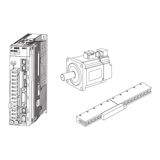
AC Servo Drives
V-EX
-
USER'S MANUAL
Model: EX002
MECHATROLINK-III Communications Reference
SGDV-2EX002 SERVOPACK
SGMMV/SGMJV/SGMAV/SGMPS/SGMGV/SGMSV/SGMCV/SGMCS/
SGLGW/SGLFW/SGLTW/SGLC/SGT Servomotor
MANUAL NO. SIEP S800001 07F
Series
Less Deviation Control
Parameters Specifically Related to
the -V-EX-series EX002
1
Outline
2
3
Advertisement
Table of Contents

Related Manuals for YASKAWA Sigma-V-EX Series


Summary of Contents for YASKAWA Sigma-V-EX Series
- Page 1 AC Servo Drives V-EX Series USER’S MANUAL Model: EX002 MECHATROLINK-III Communications Reference SGDV-2EX002 SERVOPACK SGMMV/SGMJV/SGMAV/SGMPS/SGMGV/SGMSV/SGMCV/SGMCS/ SGLGW/SGLFW/SGLTW/SGLC/SGT Servomotor Outline Less Deviation Control Parameters Specifically Related to the -V-EX-series EX002 MANUAL NO. SIEP S800001 07F...
- Page 2 Yaskawa. No patent liability is assumed with respect to the use of the information contained herein. Moreover, because Yaskawa is con- stantly striving to improve its high-quality products, the information contained in this manual is subject to change without notice.
-
Page 3: About This Manual
About this Manual This manual contains information that is required to design, test, adjust, and maintain Σ-V-EX-series EX002 servo system. The EX002 servo system enables control operation with less deviation (called less deviation control). Keep this manual in a location where it can be accessed for reference whenever required. When you use a Σ-V-EX-series EX002 servo system, read this manual together with the Σ-V Series User’s Manual Design and Maintenance. - Page 4 Description of Technical Terms The following table shows the meanings of terms used in this manual. Term Meaning Σ-V Series rotary servomotors (SGMMV, SGMJV, SGMAV, SGMPS, Servomotor SGMGV, or SGMSV), and Σ-V Series direct drive servomotors (SGMCV or SGMCS) Σ-V Series SGLGW, SGLFW, SGLTW, SGLCW linear servomotor or Linear Servomotor SGT linear slider...
- Page 5 Notation Used in this Manual • Notation for Reverse Signals The names of reverse signals (i.e., ones that are valid when low) are written with a forward slash (/) before the signal name. Notation Example BK = /BK • Notation for Parameters The notation depends on whether the parameter requires a value setting (parameter for numeric settings) or requires the selection of a function (parameter for selecting functions).
- Page 6 Related Manuals Refer to the following manuals as required. Selecting Trial Maintenance Models and Ratings and System Panels and Trial Operation Name Peripheral Specifications Design Wiring Operation and Servo Inspection Devices Adjustment Σ-V Series User's Manual Setup Rotational Motor (No.: SIEP S800000 43) Σ-V Series...
- Page 7 Trademarks MECHATROLINK is a trademark of the MECHATROLINK Members Association. Safety Information The following conventions are used to indicate precautions in this manual. Failure to heed precautions pro- vided in this manual can result in serious or possibly even fatal injury or damage to the products or to related equipment and systems.
-
Page 8: Safety Precautions
Safety Precautions This section describes important precautions that must be followed during storage, transportation, installation, wiring, operation, maintenance, inspection, and disposal. Be sure to always observe these precautions thor- oughly. WARNING • Never touch the servomotor, any rotating servomotor parts, or the machine during operation. Failure to observe this warning may result in injury. - Page 9 (cont’d) WARNING Linear Servomotors • If you have a pacemaker or any other electronic medical device, do not go near the magnetic way of the servomotor. Failure to observe this warning may result in the malfunction of the medical device. •...
- Page 10 Installation CAUTION • Never use the product in an environment subject to water, corrosive gases, flammable gases, or combustibles. Failure to observe this caution may result in electric shock or fire. • Do not step on or place a heavy object on the product. Failure to observe this caution may result in injury or malfunction.
- Page 11 Wiring CAUTION • Be sure to wire correctly and securely. Failure to observe this caution may result in motor overrun, injury, or malfunction. • Securely tighten the cable connector screws and securing mechanism. If the connector screws and securing mechanism are not secure, they may loosen during operation. •...
- Page 12 CAUTION Rotational Servomotors • Do not bundle or run the main circuit cables together with the I/O signal cables or the encoder cables in the same duct. Keep the main circuit cables separated from the I/O signal cables and the encoder cables with a gap of at least 30 cm.
- Page 13 Operation CAUTION • Do not stand within the machine's range of motion during operation. Failure to observe this caution may result in injury. • Always use the servomotor and SERVOPACK in one of the specified combinations. Failure to observe this caution may result in fire or malfunction. •...
- Page 14 • The drawings presented in this manual are typical examples and may not match the product you received. • If the manual must be ordered due to loss or damage, inform your nearest Yaskawa representative or one of the offices listed on the back of this manual.
-
Page 15: Warranty
6. Events for which Yaskawa is not responsible, such as natural or human-made disasters (2) Limitations of Liability 1. Yaskawa shall in no event be responsible for any damage or loss of opportunity to the customer that arises due to failure of the delivered product. - Page 16 2. The customer must confirm that the Yaskawa product is suitable for the systems, machines, and equipment used by the customer. 3. Consult with Yaskawa to determine whether use in the following applications is acceptable. If use in the application is acceptable, use the product with extra allowance in ratings and specifications, and provide safety measures to minimize hazards in the event of failure.
- Page 17 CSA C22.2 No.100 ∗1. Only products with derating specifications are in compliance with the UL Standards. Estimates are available for those products. Contact your Yaskawa representative for details. ∗2. SGLTW-35AH and -50AH (high-force type) are not in compliance with the UL Standards.
- Page 18 ∗2. Only Moving Coils of EU Directive-certified products (models with “-E” at the end of model numbers) are in com- pliance with the EU Directives. Estimates are available for those products. Contact your Yaskawa representative for details. For EU Directive-certified products for SGLM (models with “-E” at the end of model numbers), the con- tent of substances specified in 2011/65/EU as amended by (EU)2015/863 is below the standard value.
- Page 19 UK Conformity Assessed (UKCA) Product Model UK Regulations Designated Standards Supply of Machinery (Safety) Regulations EN ISO 13849-1: 2015 S.I. 2008/1597 EN 55011 Group 1, Class A Electromagnetic Compatibility EN 61000-6-2 Regulations EN 61000-6-4 S.I. 2016/1091 EN 61800-3 (Category C2, Second environment) SERVOPACK SGDV Electrical Equipment (Safety)
- Page 20 ∗2. Only Moving Coils of EU Directive-certified products (models with “-E” at the end of model numbers) are in com- pliance with the EU Directives. Estimates are available for those products. Contact your Yaskawa representative for details. For EU Directive-certified products for SGLM (models with “-E” at the end of model numbers), the con- tent of substances specified in S.I.
- Page 21 Safety Standards Product Model Safety Standards Standards EN ISO 13849-1: 2015 Safety of Machinery EN 60204-1 SERVOPACK SGDV EN 61508 series Functional Safety EN 61800-5-2 Functional Safety EMC EN 61326-3-1 • Safety Performance Items Standards Performance Level Safety Integrity Level EN 61508 SIL2 PFH = 1.7×10...
-
Page 22: Table Of Contents
Contents About this Manual ............iii Safety Precautions. - Page 23 Outline 1.1 Σ-V-EX-series EX002 ........1-2 1.2 SERVOPACK Ratings and Specifications .
-
Page 24: Chapter 1 Outline
1 Outline 1.2.1 Ratings Σ-V-EX-series EX002 The Σ-V-EX-series EX002 SERVOPACK enables less deviation control. For details on the less deviation control, refer to Chapter 2 Less Deviation Control. SERVOPACK Ratings and Specifications This section describes the ratings and specifications of SERVOPACKs. 1.2.1 Ratings Ratings of SERVOPACKs are as shown below. - Page 25 1.2 SERVOPACK Ratings and Specifications (4) SGDV with Three-phase, 200-V Rating: Linear Motors SGDV R70 R90 1R6 2R8 3R8 5R5 7R6 120 (Three-phase, 200 V) Continuous Output Current 0.66 0.91 11.6 18.5 19.6 32.9 54.7 [Arms] Instantaneous Max. Output 11.0 16.9 Current [Arms] None or external Built-in or external...
-
Page 26: Basic Specifications
1 Outline 1.2.2 Basic Specifications 1.2.2 Basic Specifications Basic specifications of SERVOPACKs are shown below. Drive Method Sine-wave current drive with PWM control of IGBT Rotational Motor Encoder: 17 and 20 bit (incremental/absolute) Linear scale: The signal resolution depends on the linear Feedback Linear Motor scale that is used. - Page 27 1.2 SERVOPACK Ratings and Specifications (cont’d) Phase A, B, C: line driver Encoder Output Pulse Encoder output pulse: any setting ratio (Refer to 4.4.5 Number of 7 ch Channels • Homing deceleration switch (/DEC) • External latch (/EXT 1 to 3) Input •...
- Page 28 1 Outline 1.2.2 Basic Specifications (cont’d) Input /HWBB1, /HWBB2: Baseblock signal for power module Output EDM1: Monitoring status of internal safety circuit (fixed output) Safety Function EN ISO13849-1 PL d (Category 3), IEC61508 SIL2 Standards Option Module Fully-closed module only for rotational motor or safety module Σ...
-
Page 29: 1.2.3 Mechatrolink-Iii Function Specifications
1.2 SERVOPACK Ratings and Specifications 1.2.3 MECHATROLINK-III Function Specifications The following table shows the specifications of MECHATROLINK-III. Function Specifications Communication MECHATROLINK-III Protocol 03H to EFH (Max. number of stations: 62) Station Address Use the rotary switches S1 and S2 to set the station address. MECHATROLINK-III Baud Rate 100 Mpbs... -
Page 30: Servopack Model Designation
1 Outline SERVOPACK Model Designation This section shows SERVOPACK model designation. 11th + 12th + 13th + 8th + 9th + 1st + 2nd + 5th + 6th 14th + 15th digits 10th digits digit digit 3rd digits digits EX002 SGDV –... - Page 31 Less Deviation Control 2.1 Overview ..........2-2 2.2 Restrictions .
-
Page 32: Overview
2 Less Deviation Control 2.2.1 Control Mode Restrictions Overview You can use less deviation control to reduce the error during travel and increase the locus tracking perfor- mance. This SERVOPACK is used for applications that require reference tracking performance during travel, including the prevention of locus error and the prevention of interference between the equipment and moving parts, which can be caused by the influences of position response delay. -
Page 33: Application Method
If the machine’s rigidity is low or the load regulation is high, do not use less deviation control. If the encoder’s resolution is low, Yaskawa recommends using a motor with an encoder with a 20-bit resolution. For fully-closed control, use a linear scale with a resolution that is equivalent to that of the encoder. -
Page 34: Adjustment
2 Less Deviation Control 2.4.1 Adjustment Procedure Adjustment 2.4.1 Adjustment Procedure The basic adjustment flowchart is given in the following flowchart. Make adjustments according to the machine and operating conditions. Start Adjustment Set Pn190 to n. 0 (Do not use less deviation control). Set Pn408 to n.1 (Use friction compensation). -
Page 35: 2.4.2 Adjustment Example
2.4 Adjustment 2.4.2 Adjustment Example (1) Pn193 Adjustment Example The affect of Pn193 (Feedforward Filter Time Constant) is shown here. To decrease any vibration or noise that might occur during operation, increase the setting of Pn193. This, however, might increase overshooting. Before Adjustment: Pn193 = 30 (0.3 ms) After Adjustment: Pn193 = 80 (0.8 ms) Vibration or... -
Page 36: Gain Switching
2 Less Deviation Control 2.5.1 Gain Combinations for Switching Gain Switching You can switch the gain to increase the gain during positioning to reduce the positioning time and then to reduce the gain when stopping to suppress vibration. 2.5.1 Gain Combinations for Switching Less Deviation Speed Loop Torque... -
Page 37: Chapter 3 Parameters Specifically Related To The Σ-V-Ex-Series Ex002
Parameters Specifically Related to the Σ-V-EX-series EX002 Here, the parameters that are added to the Σ-V-EX-series EX002 and the parameters that have different default settings than those of the Σ-V Standard SERVOPACKs are given. All parameters that are not given here are the same as for the Σ-V Standard SERVOPACKs. Σ... -
Page 38: Special Parameters
3 Parameters Specifically Related to the Σ-V-EX-series EX002 Special Parameters The following table lists the parameters that differentiate the EX002 from the Σ-V Series standard SERVO- PACKs. Selection for Less Deviation Control Position Setting Range Setting Unit Factory Setting When Enabled Classification 0000 to 1001 –... -
Page 39: Changed Parameters
3.2 Changed Parameters Changed Parameters The default settings of the parameters that have changed in comparison with the Σ-V standard SERVOPACKs are listed in the following table. Mode Switch Selection Settings Meanings When Enabled Classification The internal torque reference is used as n.0 the condition (level setting: Pn10C). -
Page 40: Precaution When Copying Parameters
3 Parameters Specifically Related to the Σ-V-EX-series EX002 Precaution When Copying Parameters The digital operator can be used to copy parameters between two EX002 SERVOPACKs in the Σ-V-EX series. If you copy parameters between a Σ-V-EX-series EX002 SERVOPACK and a different model of SERVO- PACK, alarms such as A.040 (Parameter Setting Error 1) will occur because different numbers of parameters are used. -
Page 41: Index
Index Index soft start time setting - - - - - - - - - - - - - - - - - - - - - - - - - - - - - - - 1-4 speed control range - - - - - - - - - - - - - - - - - - - - - - - - - - - - - - - - 1-4 speed regulation - - - - - - - - - - - - - - - - - - - - - - - - - - - - - - - - - - 1-4 storage humidity - - - - - - - - - - - - - - - - - - - - - - - - - - - - - - - - - 1-4 storage temperature - - - - - - - - - - - - - - - - - - - - - - - - - - - - - - - 1-4... - Page 42 Revision History The revision dates and numbers of the revised manuals are given on the bottom of the back cover. MANUAL NO. SIEP S800001 07B <1>-0 WEB revision number Revision number Published in Japan January 2018 Date of publication Date of Rev.
- Page 43 Phone: +81-4-2962-5151 Fax: +81-4-2962-6138 www.yaskawa.co.jp YASKAWA AMERICA, INC. 2121, Norman Drive South, Waukegan, IL 60085, U.S.A. Phone: +1-800-YASKAWA (927-5292) or +1-847-887-7000 Fax: +1-847-887-7310 www.yaskawa.com YASKAWA ELÉTRICO DO BRASIL LTDA. 777, Avenida Piraporinha, Diadema, São Paulo, 09950-000, Brasil Phone: +55-11-3585-1100 Fax: +55-11-3585-1187 www.yaskawa.com.br...
Need help?
Do you have a question about the Sigma-V-EX Series and is the answer not in the manual?
Questions and answers