Sign In
Upload
Manuals
Brands
YASKAWA Manuals
Servo Drives
SGLFW
YASKAWA SGLFW Manuals
Manuals and User Guides for YASKAWA SGLFW. We have
6
YASKAWA SGLFW manuals available for free PDF download: User Manual
YASKAWA SGLFW User Manual (447 pages)
Linear Σ Series Servomotors
Brand:
YASKAWA
| Category:
Engine
| Size: 7.09 MB
Table of Contents
Table of Contents
13
1 Outline
22
Checking Products
23
Check Items
23
Linear Servomotors
23
Servopacks
24
Serial Converter Units
25
Product Part Names
26
Linear Servomotors
26
Servopacks
27
Examples of Servo System Configurations
29
Single-Phase, 200 V Main Circuit
29
Three-Phase, 200 V Main Circuit
30
Three-Phase, 400 V Main Circuit
31
Applicable Standards
32
North American Safety Standards (UL, CSA)
32
CE Marking
32
2 Selections
33
Noise Filters, Magnetic Contactors, Surge Suppressors and DC Reactors - - - - - - - - - - - - - 2-12
33
Σ-II Series Servopacks and Applicable Linear Servomotors - - - - - - - - - - - - 2-4
33
Linear Servomotor Model Designation
34
Coil Assembly
34
Magnetic Way
34
SERVOPACK Model Designation
35
Σ-II Series Servopacks and Applicable Linear Servomotors
36
Serial Converter Units Models
38
Selecting Cables
39
Molded-Case Circuit Breaker and Fuse Capacity
43
Regenerative Resistors
45
Linear Scales
46
3 Specifications and Dimensional Drawings
47
Ratings and Specifications of SGLGW/SGLGM
48
Ratings and Specifications of SGLFW/SGLFM
52
Ratings and Specifications of SGLTW/SGLTM
55
Mechanical Specifications of Linear Servomotors
61
Quick Guide to Linear Servomotor Dimensional Drawings
62
Dimensional Drawings of SGLGW/SGLGM Linear Servomotors
63
SGLG -30 Linear Servomotors
63
SGLG -40 Linear Servomotors
66
SGLG -60 Linear Servomotors
70
SGLG -90 Linear Servomotors
74
Dimensional Drawings of SGLFW/SGLFM Linear Servomotors
76
SGLF -35 Linear Servomotors
80
SGLF -50 Linear Servomotors
82
SGLF -1Z Linear Servomotors
84
Dimensional Drawings of SGLTW / SGLTM Linear Servomotors
87
SGLT -20 Linear Servomotors
88
Sglt -35 a
90
Linear Servomotors
90
A Linear Servomotors
90
Sglt -35
92
H Linear Servomotors
93
SGLT -40 Linear Servomotors
96
SGLT -50 Linear Servomotors
99
SGLT -80 Linear Servomotors
104
4 SERVOPACK Specifications and Dimensional Drawings
105
SERVOPACK Ratings and Specifications
107
Single-Phase/Three-Phase 200
107
Three-Phase 400
107
SERVOPACK Ratings and Specifications
108
SERVOPACK Installation
110
SERVOPACK Internal Block Diagrams
112
Single-Phase 200 V, 50 W to 400 W Models
112
Three-Phase 200 V, 500 W to 1.5 Kw Models
113
Three-Phase 200 V, 2.0 Kw to 5.0 Kw Models
113
Three-Phase 200 V, 7.5 Kw Models
114
Three-Phase 400 V, 500 W to 3.0 Kw Models
114
Three-Phase 400 V, 5.0 Kw Model
115
Three-Phase 400 V, 7.5 Kw Models
115
Servopack's Power Supply Capacities and Power Losses
116
SERVOPACK Overload Characteristics and Allowable Load Mass
117
Overload Characteristics
117
Starting Time and Stopping Time
118
SERVOPACK Dimensional Drawings
119
Dimensional Drawings of Base-Mounted SERVOPACK Model
120
Single-Phase 200 V: 50 W/100 W/200 W (A5AE/01AE/02AE)
120
Single-Phase 200 V: 400 W (04AE)
121
Three-Phase 200 V: 500 W/750 W/1.0 Kw (05AE/08AE/10AE)
122
Three-Phase 200 V: 1.5 Kw (15AE) Three-Phase 400 V: 500 W/750 W/1.0 Kw/1.5 Kw (05DE/08DE/10DE/15DE)
123
Three-Phase 200 V: 2.0 Kw/3.0 Kw (20AE/30AE) Three-Phase 400 V: 2.0 Kw/3.0 Kw (20DE/30DE)
124
Three-Phase 200 V: 5.0 Kw (50AE) Three-Phase 400 V: 5.0 Kw (50DE)
125
Three-Phase 200V: 5.0 Kw (50AE) Three-Phase 400V: 5.0 Kw (50DE)
125
Three-Phase 200
125
Three-Phase 400
125
Three-Phase 200 V: 7.5 Kw (75AE)
126
Three-Phase 400 V: 7.5 Kw (75DE)
127
Dimensional Drawings of Rack-Mounted SERVOPACK Model
128
Single-Phase 200 V: 50 W/100 W/200 W (A5AE-R/01AE-R/ 02AE-R)
128
Single-Phase 200 V: 50 W/100 W/200 W (A5AE-R/01AE-R/ 02AE
128
Single-Phase 200 V: 400 W (04AE-R)
129
Three-Phase 200 V: 500 W/750 W/1.0 Kw (05AE-R/08AE-R/10AE-R)
130
Three-Phase 200 V: 1.5 Kw (15AE-R) Three-Phase 400 V: 500 W/750 W/1.0 Kw/1.5 Kw (05DE-R/08DE-R/10DE-R/15DE-R)
131
Three-Phase 200 V: 2.0 Kw/3.0 Kw (20AE-R/30AE-R) Three-Phase 400 V: 2.0 Kw/3.0 Kw (20DE-R/30DE-R)
132
Three-Phase 200 V: 2.0 Kw/3.0 Kw (20AE-R/30AE-R)
132
Three-Phase 400 V: 2.0 Kw/3.0 Kw (20DE-R/30DE
132
Three-Phase 200 V: 5.0 Kw (50AE-R) Three-Phase 400 V: 5.0 Kw (50DE-R)
133
Three-Phase 200V: 5.0Kw (50AE-R)
133
Dimensional Drawings of Duct-Ventilated SERVOPACK Model
134
Three-Phase 200 V: 7.5 Kw (75AE-P)
134
Three-Phase 400 V: 7.5 Kw (75DE-P)
135
5 Specifications and Dimensional Drawings of Serial Converter Unit
137
Serial Converter Unit Specifications
137
Analog Signal Input Timing
138
Dimensional Drawings of Serial Converter Unit
139
Linear Scale Without Cable for Hall Sensor by Heidenhain
139
Linear Scale Without Cable for Hall Sensor by Renishaw
140
Linear Scale with Cable for Hall Sensor by Heidenhain
141
Linear Scale with Cable for Hall Sensor by Renishaw
143
6 Specifications and Dimensional Drawings of Cables and Peripheral Devices
146
Linear Servomotor Main Circuit Cables
146
Cables for Connecting Serial Converter Units
152
Cables for Connecting Linear Scales
153
Cables for Connecting Hall Sensors
154
Flexible Cables
155
Linear Servomotor Main Circuit Cables
155
Cables for Connecting Serial Converter Units
155
Cables for Connecting Linear Scales
155
SERVOPACK Main Circuit Wire Size
157
Cable Types
157
I/O Signal Cables for CN1 Connector
160
Standard Cables
160
Connector Type and Cable Size
160
Connection Diagram
162
Peripheral Devices
163
Cables for Connecting Personal Computers
163
Digital Operator
163
Cables for Analog Monitor
164
Connector Terminal Block Converter Unit
165
External Regenerative Resistor
166
External Regenerative Resistor
168
Regenerative Resistor
169
Molded-Case Circuit Breaker (MCCB)
170
Noise Filter
171
Magnetic Contactor
175
Surge Suppressor
179
DC Reactor for Harmonic Suppression
181
DC Reactor for Harmonic Suppression
182
Variable Resistor for Speed and Force Setting
183
Encoder Signal Converter Unit
184
MECHATROLINK I/F Unit
185
Devicenet I/F Unit
186
PROFIBUS-DP I/F Unit
187
INDEXER Module
189
7 Wiring
191
Linear Servomotor Installation
192
Introduction
192
SGLGW and SGLGM Linear Servomotors (Coreless Types)
193
SGLFW and SGLFM Linear Servomotor (F-Shaped with Core)
196
SGLTW and SGLTM Linear Servomotor (T Type with Iron Core)
200
Wiring Main Circuit
205
Names and Functions of Main Circuit Terminals
205
Wiring Main Circuit Power Supply Connector (Spring Type)
207
Typical Main Circuit Wiring Examples
208
Wiring Encoders
211
Connecting an Encoder (CN2) and Output Signals from the SERVOPACK
211
Encoder Connector (CN2) Terminal Layout
211
Examples of I/O Signal Connections
212
Speed Control Mode
212
Position Control Mode
213
Force Control Mode
214
I/O Signal Connector (CN1) Terminal Layout
215
I/O Signal (CN1) Names and Functions
216
Interface Circuit
218
Others
221
Wiring Precautions
221
Wiring for Noise Control
222
Using more than One SERVOPACK
225
Operating Conditions on 400-V Power Supply Voltage
226
DC Reactor for Harmonic Suppression
227
Connecting Regenerative Resistors
228
Regenerative Power and Regenerative Resistance
228
Connecting External Regenerative Resistors
228
8 Digital Operator/Panel Operator
233
Functions on Digital Operator/Panel Operator
234
Connecting the Digital Operator
234
Key Names and Functions
235
Basic Mode Selection and Operation
236
Status Display
238
Operation in Utility Function Mode
240
List of Utility Function Modes
240
Operation in Utility Function Mode (Fn )
241
Alarm Traceback Data Display (Fn000)
241
JOG Mode Operation (Fn002)
242
Zero-Point Search Mode (Fn003)
243
Parameter Settings Initialization (Fn005)
244
Alarm Traceback Data Clear (Fn006)
245
Automatic Offset-Adjustment of Motor Current Detection Signal (Fn00E)
246
Manual Offset-Adjustment of Motor Current Detection Signal (Fn00F)
247
Password Setting (Protects Parameters from Being Changed) (Fn010)
248
Motor Models Display (Fn011)
249
Software Version Display (Fn012)
250
Application Module Detection Results Clear (Fn014)
251
Operation in Parameter Setting Mode (Pn )
252
Setting Parameters
252
Input Circuit Signal Allocation
256
Output Circuit Signal Allocation
260
Operation in Monitor Mode (un )
262
List of Monitor Modes
262
Sequence I/O Signal Monitor Display
263
Operation in Monitor Mode
264
Monitor Display of Reference Pulse Counter and Feedback Pulse Counter
265
Allowable Maximum Motor Speed for Dividing Ratio Monitor (for the Software Version 32 or Later)
266
Hall Sensor Signal Monitor (for the Software Version 32 or Later)
267
Advertisement
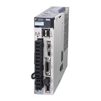
YASKAWA SGLFW User Manual (398 pages)
E-V Series, Linear Servomotors
Brand:
YASKAWA
| Category:
Servo Drives
| Size: 21.84 MB
Table of Contents
About this Manual
4
Outline
4
Panel Operator
5
Safety Precautions
7
Warranty
13
Harmonized Standards
15
Table of Contents
17
Chapter 1 Outline
24
V Series Servopacks
25
Part Names
25
SERVOPACK Ratings and Specifications
26
Ratings
26
Basic Specifications
27
Speed/Position/Force Control
30
SERVOPACK Internal Block Diagrams
31
Single-Phase 100 V, SGDV-R70F05A, -R90F05A, -2R1F05A Models
31
Single-Phase 100 V, SGDV-2R8F05A Model
31
Three-Phase 200 V, SGDV-R70A05, -R90A05, -1R6A05 Models
32
Three-Phase 200 V, SGDV-2R8A05 Model
32
Three-Phase 200 V, SGDV-3R8A05A, -5R5A05A, -7R6A05A Models
33
Three-Phase 200 V, SGDV-120A05A Model
33
Three-Phase 200 V, SGDV-180A05A, -200A05A Models
34
Three-Phase 200 V, SGDV-330A05A Model
34
Three-Phase 200 V, SGDV-550A05A Models
35
Three-Phase 400 V, SGDV-1R9D05A, -3R5D05A, -5R4D05A Models
35
Three-Phase 400 V, SGDV-8R4D05A, -120D05A Models
36
Three-Phase 400 V, SGDV-170D05A Model
36
Three-Phase 400 V, SGDV-260D05A Model
37
Examples of Servo System Configurations
38
Connecting to SGDV-F05A SERVOPACK
38
Connecting to SGDV-A05 SERVOPACK
39
Connecting to SGDV-D05A SERVOPACK
41
SERVOPACK Model Designation
42
Inspection and Maintenance
43
Chapter 2 Panel Operator
44
Overview
45
Names and Functions
45
Display Selection
45
Status Display
46
Utility Functions (Fn)
47
Parameters (Pn)
48
Parameter Classification
48
Notation for Parameters
48
Setting Parameters
49
Monitor Displays (Un)
52
Chapter 3 Wiring and Connection
54
Main Circuit Wiring
55
Main Circuit Terminals
55
Using a Standard Power Supply (Single-Phase 100 V, Three-Phase 200 V, or Three-Phase 400 V)
56
Using a Standard Power Supply (Single-Phase 100 V, Three-Phase 200 V, or Three-Phase 400 V)
56
Using the SERVOPACK with Single-Phase, 200 V Power Input
63
Using the SERVOPACK with a DC Power Input
66
Using more than One SERVOPACK
68
General Precautions for Wiring
69
I/O Signal Connections
70
I/O Signal (CN1) Names and Functions
70
Safety Function Signal (CN8) Names and Functions
72
Example of I/O Signal Connections in Speed Control
73
Example of I/O Signal Connections in Position Control
74
Example of I/O Signal Connections in Force Control
75
I/O Signal Allocations
76
Input Signal Allocations
76
Output Signal Allocations
80
Examples of Connection to Host Controller
83
Reference Input Circuit
83
Sequence Input Circuit
85
Sequence Output Circuit
87
Linear Scale Connection
89
Linear Scale Signal (CN2) Names and Functions
89
Serial Converter Unit
89
Linear Scale Connection Examples
92
Connecting Regenerative Resistors
96
Setting Regenerative Resistor Capacity
98
Noise Control and Measures for Harmonic Suppression
99
Wiring for Noise Control
99
Precautions on Connecting Noise Filter
101
Connecting a Reactor for Harmonic Suppression
102
Chapter 4 Trial Operation
104
Inspection and Checking before Trial Operation
105
Trial Operation for Servomotor Without Load
105
Trial Operation for Servomotor Without Load from Host Reference
106
Inspecting Connection and Status of Input Signals
107
Trial Operation in Speed Control
109
Trial Operation under Position Control from the Host Controller
110
With the SERVOPACK Used for Speed Control
110
Trial Operation in Position Control
111
Trial Operation with the Servomotor Connected to the Machine
112
Test Without Motor Function
114
Motor Information
114
Motor Position and Speed Responses
114
Limitations
115
Operator Displays During Testing Without Motor
116
Chapter 5 Operation
118
Control Method Selection
120
Basic Functions Settings
121
Servo on Signal
121
Polarity Detection
121
Servomotor Movement Direction
123
Overtravel
124
Holding Brakes
127
Stopping Servomotors after /S-ON Turned off or Alarm Occurrence
131
Instantaneous Power Interruption Settings
133
Motor Maximum Speed
133
SEMI F47 Function
134
Setting Motor Overload Detection Level
137
Speed Control
139
Basic Settings for Speed Control
139
Reference Offset Adjustment
140
Soft Start
143
Speed Reference Filter
143
Zero Clamp Function
144
Encoder Output Pulses
146
Encoder Output Pulses
149
Setting Encoder Output Pulse
151
Setting Speed Coincidence Signal
152
Position Control
153
Basic Settings for Position Control
154
Clear Signal Setting
158
Reference Pulse Input Multiplication Switching Function
159
Electronic Gear
160
Smoothing
163
Positioning Completed Signal
164
Positioning Near Signal
165
Reference Pulse Inhibit Function
166
Force Control
167
Basic Settings for Force Control
167
Reference Offset Adjustment
168
Force Reference Filter
171
Speed Limit in Force Control
171
Internal Set Speed Control
173
Basic Settings for Speed Control with an Internal Set Speed
173
Example of Operating with Internal Set Speeds
175
Combination of Control Methods
176
Switching Internal Set Speed Control (Pn000.1 = 4, 5, or 6)
176
Switching Other than Internal Set Speed Control (Pn000.1 = 7, 8 or 9)
179
Switching Other than Internal Set Speed Control (Pn000.1 = a or B)
179
Limiting Force
180
Internal Force Limit
180
External Force Limit
181
Force Limiting Using an Analog Voltage Reference
182
Force Limiting Using an External Force Limit and Analog Voltage Reference
184
Checking Output Force Limiting During Operation
186
Absolute Linear Scales
187
Absolute Data Request Signal (SEN)
187
Absolute Data Reception Sequence
189
Other Output Signals
192
Servo Alarm Output Signal (ALM) and Alarm Code Output Signals (ALO1, ALO2, and ALO3)
192
Warning Output Signal (/WARN)
193
Movement Detection Output Signal (/TGON)
194
Servo Ready Output Signal (/S-RDY)
194
Www.dadehpardazan.ir 88594014-15
194
Safety Function
195
Hard Wire Base Block (HWBB) Function
195
External Device Monitor (EDM1)
199
Application Example of Safety Functions
201
Confirming Safety Functions
202
Precautions for Safety Functions
202
Chapter 6 Adjustments
206
Type of Adjustments and Basic Adjustment Procedure
206
Adjustments
206
Basic Adjustment Procedure
208
Monitoring Operation During Adjustment
209
Safety Precautions on Adjustment of Servo Gains
212
Tuning-Less Function
214
Tuning-Less Levels Setting (Fn200) Procedure
217
Related Parameters
220
Advanced Autotuning (Fn201)
221
Advanced Autotuning
221
Advanced Autotuning Procedure
224
Related Parameters
230
Advanced Autotuning by Reference (Fn202)
231
Advanced Autotuning by Reference
231
Advanced Autotuning by Reference Procedure
233
Related Parameters
237
One-Parameter Tuning (Fn203)
238
One-Parameter Tuning
238
One-Parameter Tuning Procedure
239
One-Parameter Tuning Example
246
Related Parameters
247
Anti-Resonance Control Adjustment Function (Fn204)
248
Anti-Resonance Control Adjustment Function
248
Anti-Resonance Control Adjustment Function Operating Procedure
249
Related Parameters
253
Vibration Suppression Function (Fn205)
254
Vibration Suppression Function
254
Vibration Suppression Function Operating Procedure
255
Related Parameters
258
Additional Adjustment Function
259
Switching Gain Settings
259
Manual Adjustment of Friction Compensation
263
Current Control Mode Selection Function
265
Current Gain Level Setting
265
Speed Detection Method Selection
265
Compatible Adjustment Function
266
Feedforward Reference
266
Force Feedforward
266
Speed Feedforward
268
Proportional Control
269
Mode Switch (P/PI Switching)
270
Force Reference Filter
272
Force Reference Filter
273
Position Integral
274
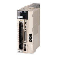
Yaskawa SGLFW User Manual (357 pages)
AC Servo Drives Linear Motor Analog Voltage and Pulse Train Reference SGDV Servopack
Brand:
Yaskawa
| Category:
Servo Drives
| Size: 9.4 MB
Table of Contents
Table of Contents
13
About this Manual
3
Safety Precautions
6
Applicable Standards
12
Table of Contents
13
Chapter 1 Outline
20
Part Names
20
Σ-V Series Servopacks
20
SERVOPACK Ratings and Specifications
21
Ratings
21
Basic Specifications
22
Speed/Position/Force Control Modes
24
SERVOPACK Internal Block Diagrams
25
Single-Phase 100 V, SGDV-R70F05A, -R90F05A, -2R1F05A Models
25
Single-Phase 100 V, SGDV-2R8F05A Model
25
Three-Phase 200 V, SGDV-R70A05A, -R90A05A, -1R6A05A Models
26
Three-Phase 200 V, SGDV-2R8A05A Model
26
Three-Phase 200 V, SGDV-3R8A05A, -5R5A05A, -7R6A05A Models
27
Three-Phase 200 V, SGDV-120A05A Model
27
Three-Phase 200 V, SGDV-180A05A, -200A05A Models
28
Three-Phase 200 V, SGDV-330A05A Model
28
Three-Phase 200 V, SGDV-470A05A, -550A05A Models
29
Three-Phase 200 V SGDV-590A05A, -780A05A Models
29
Three-Phase 400 V, SGDV-1R9D05A, -3R5D05A, -5R4D05A Models
30
Three-Phase 400 V, SGDV-8R4D05A, -120D05A Models
30
Three-Phase 400 V, SGDV-170D05A Model
31
Three-Phase 400 V, SGDV-210D05A, -260D05A Models
31
Three-Phase 400 V SGDV-280D05A, -370D05A Models
32
Examples of Servo System Configurations
33
Connecting to SGDV- F05A SERVOPACK
33
A05A Servopack
34
D05A Servopack
35
SERVOPACK Model Designation
36
Inspection and Maintenance
37
2 Panel Operator
38
Chapter 2 Panel Operator
39
Display Mode Selection
39
Panel Operator
39
Status Display Mode
40
Utility Function Mode (Fn )
41
How to Read a Parameter Explanation
42
Explanation Method for Parameter Setting Type
42
Explanation Method for Function Selection Type
42
Explanation Method for Tuning Parameters
43
Parameter Setting Mode (Pn )
44
Parameter Setting Mode for Parameter Setting Type
44
Parameter Setting Mode for Function Selection Type
47
Monitor Mode (un )
48
3 Wiring and Connection
49
Chapter 3 Wiring and Connection
50
Main Circuit Wiring
50
Names and Functions of Main Circuit Terminals
51
SERVOPACK Main Circuit Wire Size
52
Typical Main Circuit Wiring Examples
54
General Precautions for Wiring
57
Precautions When Using the SERVOPACK with a DC Power Input
58
Precautions When Using the SERVOPACK with Single-Phase, 200 V Power Input
60
Precautions When Using more than One SERVOPACK
63
Designing a Power on Sequence
64
I/O Signal Connections
65
I/O Signal (CN1) Names and Functions
65
I/O Signal Connector (CN1) Terminal Layout
67
Safety Function Signal (CN8) Names and Functions
68
Safety Function Signal (CN8) Terminal Layout
68
Example of I/O Signal Connections in Speed Control
69
Example of I/O Signal Connections in Position Control
70
Example of I/O Signal Connections in Force Control
71
I/O Signal Allocations
72
Input Signal Allocations
72
Output Signal Allocations
76
Examples of Connection to Host Controller
80
Connection Examples of Reference Input Circuits to SERVOPACK
80
Connection Examples of Sequence Input Circuits to SERVOPACK
82
Connection Examples of Output Circuits to SERVOPACK
83
Examples of Linear Scale Connection
86
Connection Example of a Linear Scale
86
CN2 Linear Scale Connector Terminal Layout
87
Connecting Regenerative Resistors
88
Setting Regenerative Resistor Capacity
90
Noise Control and Measures for Harmonic Suppression
91
Wiring for Noise Control
91
Precautions on Connecting Noise Filter
93
Connecting DC Reactor for Harmonic Suppression
95
4 Trial Operation
96
Chapter 4 Trial Operation
97
Inspection and Checking before Trial Operation
97
Trial Operation for Linear Servomotor Without Load
97
Trial Operation for Linear Servomotor Without Load from Host
97
Reference
97
Trial Operation for Linear Servomotor Without Load from Host Reference
97
Trial Operation with the Linear Servomotor Connected to the Machine
98
Test Without Motor Function
100
Limitations
100
Operating Procedure
101
Related Parameters
102
Operator Display During Testing Without Motor
102
5 Operation
104
Chapter 5 Operation
106
Control Selection
106
Setting Common Basic Functions
107
Servo on Signal
107
Servomotor Movement Direction
108
Overtravel
109
Stopping Servomotors after /S_ON Turned off or Alarm Occurrence
112
Power Loss Settings
114
Motor Maximum Speed
114
SEMI F47 Function
115
SEMI F47 Function (Force Limit Function for Low Power Supply Voltage for Main Circuit)
115
Setting Motor Overload Detection Level
118
Operating Using Speed Control with Analog Voltage Reference
120
Basic Settings for Speed Control
120
Reference Offset Adjustment
122
Soft Start
124
Speed Reference Filter
125
Zero Clamp Function
126
Encoder Pulse Output
128
Encoder Pulse Output Setting
130
Speed Coincidence Signal Setting
131
Operating Using Position Control with Pulse Train Reference
132
Basic Settings for Position Control Mode
132
Clear Signal
137
Electronic Gear
138
Smoothing
140
Positioning Completed Output Signal
141
Positioning Near Signal
142
Reference Pulse Inhibit Function
143
Operating Using Force Control with Analog Voltage Reference
145
Basic Settings for Force Control Mode
145
Adjustment of Reference Offset
146
Speed Limit in Force Control
148
Operating Using Speed Control with an Internally Set Speed
151
Basic Settings for Speed Control with an Internally Set Speed
151
Example of Operating with Internally Set Speed
153
Control Selection
155
Combination of Control Modes
155
Switching Internally Set Speed Control (Pn000.1 = 4, 5, or 6)
155
Switching Other than Internally Set Speed Control (Pn000.1 = 7, 8, 9, A, or B)
156
Limiting Force
157
Internal Force Limit
157
External Force Limit
158
Force Limiting Using an Analog Voltage Reference
159
Force Limiting Using an External Force Limit and Analog Voltage Reference
160
Checking Output Force Limiting During Operation
162
Setting Absolute Linear Scale
163
Setup Procedure
163
Setting the SEN Signal
164
Designing a Power on Sequence
165
Polarity Detection (Fn080)
165
Origin Setting (Fn020)
166
Absolute Encoder Reception Sequence
167
Output Signals Used in All Control Modes
171
Servo Alarm Output Signal (ALM) and Alarm Code Output Signals (ALO1, ALO2, and ALO3)
171
Warning Output Signal (/WARN)
172
Movement Detection Output Signal (/TGON)
173
Servo Ready Output Signal (/S-RDY)
173
Safety Function
174
Hard Wire Base Block (HWBB) Function
174
External Device Monitor (EDM1)
178
Application Example of Safety Functions
180
Confirming Safety Functions
181
Precautions for Safety Functions
181
6 Adjustments
182
Adjustments and Basic Adjustment Procedure
184
Adjustments
184
Basic Adjustment Procedure
185
Monitoring Analog Signals
186
Safety Precautions on Adjustment of Servo Gains
188
Chapter 6 Adjustments
184
Tuning-Less Function
191
Tuning-Less Operating Procedure
192
Advanced Autotuning (Fn201)
196
Advanced Autotuning
196
Advanced Autotuning (Fn201)
198
Advanced Autotuning
199
Advanced Autotuning Procedure
201
Related Parameters
205
Advanced Autotuning by Reference (Fn202)
206
Advanced Autotuning by Reference
206
Advanced Autotuning by Reference Procedure
211
Related Parameters
213
One-Parameter Tuning (Fn203)
214
One-Parameter Tuning
214
One-Parameter Tuning (Fn203)
215
One-Parameter Tuning
216
One-Parameter Tuning Procedure
216
One-Parameter Tuning Example
220
Related Parameters
221
Anti-Resonance Control Adjustment Function (Fn204)
222
Anti-Resonance Control Adjustment Function
222
Anti-Resonance Control Adjustment Function Operating Procedure
223
Related Parameters
227
Vibration Suppression Function (Fn205)
228
Vibration Suppression Function
228
Vibration Suppression Function Operating Procedure
229
Related Parameters
231
Servo Gain Adjustment Application Function
232
Feedforward Reference
233
Force Feedforward
234
Speed Feedforward
235
Proportional Control Operation (Proportional Operation Reference)
236
Using the Mode Switch (P/PI Switching)
237
Switching Gain Settings
241
Force Reference Filter
245
Position Integral Time Constant
247
Friction Compensation
248
Current Control Mode Selection
249
Current Gain Level Setting
250
Speed Detection Method Selection
250
Advertisement
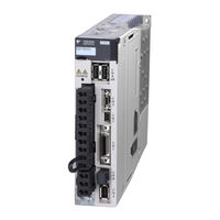
YASKAWA SGLFW User Manual (311 pages)
AC Servo Drives; Linear Motor Command Option Attachable Type
Brand:
YASKAWA
| Category:
Servo Drives
| Size: 11.26 MB
Table of Contents
About this Manual
3
Safety Precautions
7
Warranty
13
Applicable Standards
15
Table of Contents
16
Chapter 1 Outline
22
Σ-V Series Servopacks
22
Part Names
22
SERVOPACK Ratings and Specifications
23
Ratings
23
Basic Specifications
25
SERVOPACK Internal Block Diagrams
28
Single-Phase 100-V, SGDV-R70FE5A, -R90FE5A, -2R1FE5A Models
28
Single-Phase 100-V, SGDV-2R8FE5A Model
28
Single-Phase 200-V, SGDV-120AE5A008000 Model
29
Three-Phase 200-V, SGDV-R70AE5A, -R90AE5A, -1R6AE5A Models
29
Three-Phase 200-V, SGDV-2R8AE5A Model
30
Three-Phase 200-V, SGDV-3R8AE5A, -5R5AE5A, -7R6AE5A Models
30
Three-Phase 200-V, SGDV-120AE5A Model
31
Three-Phase 200-V, SGDV-180AE5A, -200AE5A Models
31
Three-Phase 200-V, SGDV-330AE5A Model
32
Three-Phase 200-V, SGDV-550AE5A Model
32
Three-Phase 400-V, SGDV-1R9DE5A, -3R5DE5A, -5R4DE5A Models
33
Three-Phase 400-V, SGDV-8R4DE5A, -120DE5A Models
33
Three-Phase 400-V, SGDV-170DE5A Model
34
Three-Phase 400-V, SGDV-260DE5A Model
34
Examples of Servo System Configurations
35
Connecting to SGDV- FE5A SERVOPACK
35
Ae5A Servopack
36
Connecting to SGDV- DE5A SERVOPACK
38
SERVOPACK Model Designation
39
Inspection and Maintenance
40
Chapter 2 Panel Display and Operation of Digital Operator
42
Panel Display
42
Status Display
42
Alarm and Warning Display
42
Hard Wire Base Block Display
42
Displays During Overtravel
42
Utility Function Mode (Fn )
43
Parameter
44
Parameter Classifications
44
Parameter Notation
44
Parameter Setting Methods
45
Monitor Mode (un )
47
Chapter 3 Wiring and Connection
49
Main Circuit Wiring
49
Main Circuit Terminals
49
Using a Standard Power Supply Input (Single-Phase 100-V, Three-Phase 200-V, or Three-Phase 400-V)
50
General Precautions for Wiring
58
Using the SERVOPACK with Single-Phase, 200-V Power Input
59
Using the SERVOPACK with a DC Power Input
62
Using more than One SERVOPACK
64
I/O Signal Connections
65
I/O Signal (CN1) Names and Functions
65
Safety Function Signal (CN8) Names and Functions
66
Example of I/O Signal Connections
67
I/O Signal Allocations
68
Input Signal Allocations
68
Output Signal Allocation
70
Connection to Host Controller
71
Sequence Input Circuits
71
Sequence Output Circuits
73
Wiring Communications Using Command Option Modules
75
Linear Scale Connections
76
Linear Scale Signal (CN2) Names and Functions
76
Connection Example of a Linear Scale
76
Serial Converter Unit Specifications
78
Regenerative Resistors Connections
80
Connecting Regenerative Resistors
80
Setting Regenerative Resistor Capacity
82
Noise Control and Measures for Harmonic Suppression
83
Wiring for Noise Control
83
Precautions on Connecting Noise Filter
85
Connecting AC/DC Reactor for Harmonic Suppression
87
Chapter 4 Operation
90
Option Module Function Settings
90
Setting Switches S1 and S2 for Option Module Functions
90
Settings for Common Basic Functions
91
Inspection and Checking before Operation
91
Linear Servomotor Movement Direction
92
Overtravel
93
Electronic Gear
96
Encoder Output Pulse
99
Encoder Output Pulse Setting
101
Holding Brakes
102
Stopping Linear Servomotor after Receiving Servo off Command or Alarm Occurrence
106
Instantaneous Power Interruption Settings
108
Motor Maximum Speed
108
SEMI-F47 Function (Force Limit Function for Low Power Supply Voltage for Main Circuit)
109
Setting Motor Overload Detection Level
112
Test Without Motor Function
114
Related Parameters
114
Limitations
115
Digital Operator Display During Testing Without Motor
116
Limiting Force
117
Internal Force Limit
117
External Force Limit
118
Checking Output Force Limiting During Operation
119
Setting Absolute Linear Scale
120
Setup Procedure
120
Origin Setting (Fn020)
121
Polarity Detection (Fn080)
122
Absolute Linear Scale Reception Sequence
123
Other Output Signals
126
Servo Alarm Output Signal (ALM)
126
Warning Output Signal (/WARN)
126
Movement Detection Output Signal (/TGON)
127
Servo Ready Output Signal (/S-RDY)
127
Safety Function
128
Hard Wire Base Block (HWBB) Function
128
External Device Monitor (EDM1)
133
Application Example of Safety Functions
135
Confirming Safety Functions
136
Connecting a Safety Device
137
Precautions for Safety Functions
138
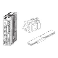
YASKAWA SGLFW User Manual (276 pages)
AC Servodrive, Linear Motor, Communications Reference
Brand:
YASKAWA
| Category:
Servo Drives
| Size: 5.52 MB
Table of Contents
About this Manual
3
Safety Precautions
6
Applicable Standards
12
Table of Contents
13
Chapter 1 Outline
18
Σ-V Series Servopacks
18
Part Names
18
SERVOPACK Ratings and Specifications
19
Ratings
19
Basic Specifications
20
MECHATROLINK-II Function Specifications
22
Examples of Servo System Configurations
23
Connecting to SGDV- F15A SERVOPACK
23
A15A Servopack
24
Connecting to SGDV
24
D15A Servopack
25
Connecting to SGDV
25
SERVOPACK Model Designation
26
Inspection and Maintenance
27
Chapter 2 Panel Display and Operation of Digital Operator
29
Panel Display
29
Status Display
29
Alarm and Warning Display
29
Mode Test Without Motor Display
29
Monitor Mode (un )
30
Utility Function Mode (Fn )
30
How to Read a Parameter Explanation
32
Explanation Method for Parameter Setting Type
32
Explanation Method for Function Selection Type
32
Explanation Method for Tuning Parameters
32
Parameter Setting Mode (Pn )
33
Parameter Setting Mode for Parameter Setting Type
33
Parameter Setting Mode for Function Selection Type
35
Monitor Mode (un )
36
Chapter 3 Wiring and Connection
38
Main Circuit Wiring
38
Names and Functions of Main Circuit Terminals
39
SERVOPACK Main Circuit Wire Size
40
Typical Main Circuit Wiring Examples
42
General Precautions for Wiring
45
Precautions When Using the SERVOPACK with a DC Power Input
46
Precautions When Using the SERVOPACK with Single-Phase, 200 V Power Input
48
Precautions When Using more than One SERVOPACK
51
Designing a Power on Sequence
52
I/O Signal Connections
53
I/O Signal (CN1) Names and Functions
53
I/O Signal Connector (CN1) Terminal Layout
54
Safety Function Signal (CN8) Names and Functions
55
Safety Function Signal (CN8) Terminal Layout
55
Example of I/O Signal Connections
56
I/O Signal Allocation
57
Input Signal Allocation
57
Output Signal Allocation
58
Examples of Connection to Host Controller
60
Connection Examples of Input Circuits to SERVOPACK
60
Connection Examples of Sequence Input Circuits to SERVOPACK
61
Connection Examples of Output Circuits to SERVOPACK
62
Wiring MECHATROLINK-II Communications
64
Examples of Encoder Connection
65
Connection Example of an Encoder
65
CN2 Encoder Connector Terminal Layout
66
Connecting Regenerative Resistors
67
Setting Regenerative Resistor Capacity
68
Noise Control and Measures for Harmonic Suppression
69
Wiring for Noise Control
69
Precautions on Connecting Noise Filter
71
Connecting DC Reactor for Harmonic Suppression
73
Chapter 4 Operation
74
MECHATROLINK-II Communications Settings
75
Setting Switches SW1 and SW2
75
MECHATROLINK-II Commands
76
Setting Common Basic Functions
77
Servomotor Movement Direction
77
Overtravel
78
Stopping Method for Servomotor after Servo off or Alarm Occurrence
81
Power Loss Settings
83
Motor Maximum Speed
83
Force Limit Function for Low Power Supply Voltage for Main Circuit (SEMI-F47 Function)
84
Setting Motor Overload Detection Level
86
Trial Operation
88
Inspection and Checking before Trial Operation
88
Trial Operation Via MECHATROLINK-II
89
Electronic Gear
90
Test Without Motor Function
92
Limitations
92
Related Parameters
93
Digital Operator Display During Testing Without Motor
94
Safety Function
95
Hard Wire Base Block (HWBB) Function
95
External Device Monitor (EDM1)
100
Application Example of Safety Functions
102
Confirming Safety Functions
103
Precautions for Safety Functions
103
Chapter 5 Adjustments
104
Adjustments and Basic Adjustment Procedure
106
Adjustments
106
Basic Adjustment Procedure
107
Monitoring Analog Signals
108
Safety Precautions on Adjustment of Servo Gains
110
Tuning-Less Function
113
Tuning-Less Operating Procedure
115
Advanced Autotuning (Fn201)
117
Advanced Autotuning
117
Advanced Autotuning (Fn201)
120
Advanced Autotuning
120
Advanced Autotuning Procedure
122
Related Parameters
126
Advanced Autotuning by Reference (Fn202)
127
Advanced Autotuning by Reference
127
Advanced Autotuning by Reference Procedure
131
Related Parameters
133
One-Parameter Tuning (Fn203)
134
One-Parameter Tuning
134
One-Parameter Tuning (Fn203)
135
One-Parameter Tuning
136
One-Parameter Tuning Procedure
137
One-Parameter Tuning Example
140
Related Parameters
141
Anti-Resonance Control Adjustment Function (Fn204)
142
Anti-Resonance Control Adjustment Function
142
Anti-Resonance Control Adjustment Function Operating Procedure
143
Related Parameters
147
Vibration Suppression Function (Fn205)
148
Vibration Suppression Function
148
Vibration Suppression Function Operating Procedure
149
Related Parameters
151
Servo Gain Adjustment Application Function
152
Feedforward Reference
153
Using the Mode Switch (P/PI Switching)
153
Switching Gain Settings
157
Force Reference Filter
161
Position Integral Time Constant
163
Friction Compensation
164
Current Control Mode Selection
166
Current Gain Level Setting
166
Speed Detection Method Selection
166
YASKAWA SGLFW User Manual (176 pages)
E-V Series AC Servo Drives
Brand:
YASKAWA
| Category:
Controller
| Size: 10.56 MB
Table of Contents
About this Manual
4
Safety Precautions
9
Warranty
17
Applicable Standards
19
Table of Contents
20
1 Overview of Setup
22
2 Installation
24
Installation Environment and Applicable Standards
25
Linear Servomotor Installation Environment
25
SERVOPACK Installation Environment
26
2.1 Installation Environment and Applicable Standards
26
Installation Conditions for Applicable Standards
27
Linear Servomotor Installation
28
SGLGW and SGLGM Linear Servomotors (Coreless Type)
28
SGLFW and SGLFM Linear Servomotors (F-Type Iron Core)
31
Www.dadehpardazan.ir
32
SGLTW and SGLTM Linear Servomotors (T-Type Iron Core)
37
SGLC Linear Servomotors (Cylinder Type)
44
Linear Scale Installation and Adjustment
50
Installation Conditions
50
Installation
53
Adjustment
55
SERVOPACK Installation
56
Orientation
56
Installation Standards
58
EMC Installation Conditions
60
SGDV-05 (Analog Pulse Model)
60
SGDV-15 (M-II Model)
68
SGDV-25 (M-III Model)
76
SGDV-E5A (Command Option Attachable Type)
84
Other Precautions
84
3 Wiring and Connection
86
Precautions for Wiring
88
System Configuration Diagram
89
Connecting to SGDV-05 SERVOPACK (Analog Pulse Model)
89
Connecting to SGDV-05 SERVOPACK
89
Connecting to SGDV-15 SERVOPACK (M-II Model)
93
Connecting to SGDV-15 SERVOPACK
93
(M-II Model)
93
Connecting to SGDV-25 SERVOPACK (M-III Model)
97
Connecting to SGDV-25 SERVOPACK
97
Connecting to SGDV-E5A SERVOPACK
101
Connecting to SGDV-E5A SERVOPACK (Command Option Attachable Type)
101
(Command Option Attachable Type)
105
Main Circuit Wiring
105
Main Circuit Terminals
105
When Using a Standard Power Supply Input
107
When Using a Standard Power Supply Input (Single-Phase 100 V, Three-Phase 200 V, or Three-Phase 400 V)
107
When Using the SERVOPACK with a Single-Phase 200 V Power Input
112
When Using the SERVOPACK with a Single-Phase
112
Power Input
112
When Using the SERVOPACK with a DC Power Input
115
Www.dadehpardazan.ir 88594014-15
116
When Using more than One SERVOPACK
119
General Precautions for Wiring
120
Wiring the Spring Type Main Circuit Terminal Connector
121
Connecting Regenerative Resistors
123
Connecting Regenerative Resistor
123
Setting the Regenerative Resistor Capacity
126
Linear Scale Connections
127
Linear Scale Signal (CN2) Names and Functions
127
Linear Scale Connection Examples
128
3.5.2 Linear Scale Connection Examples
131
Advertisement
Related Products
YASKAWA SGLGW
YASKAWA SGLTW
YASKAWA SGLC
YASKAWA SGLG
YASKAWA SGLF
YASKAWA SGLT
Yaskawa SGLCW
YASKAWA SGM7D-34G
YASKAWA SGD7S 020 Series
YASKAWA SGM-02A
YASKAWA Categories
Controller
DC Drives
Servo Drives
Robotics
Control Unit
More YASKAWA Manuals
Login
Sign In
OR
Sign in with Facebook
Sign in with Google
Upload manual
Upload from disk
Upload from URL