
Related Manuals for Waters SYNAPT G2


Summary of Contents for Waters SYNAPT G2
- Page 1 Waters SYNAPT G2 Mass Spectrometry System Operator’s Overview and Maintenance Guide Revision A Copyright © Waters Corporation 2009 All rights reserved...
-
Page 2: Copyright Notice
Corporation assumes no responsibility for any errors that may appear in this document. This document is believed to be complete and accurate at the time of publication. In no event shall Waters Corporation be liable for incidental or consequential damages in connection with, or arising from, its use. -
Page 3: Customer Comments
Customer comments Waters’ Technical Communications department invites you to tell us of any errors you encounter in this document or to suggest ideas for otherwise improving it. Please help us better understand what you expect from our documentation so that we can continuously improve its accuracy and usability. -
Page 4: Contacting Waters
Contacting Waters ® Contact Waters with enhancement requests or technical questions regarding the use, transportation, removal, or disposal of any Waters product. You can reach us via the Internet, telephone, or conventional mail. Waters contact information Contacting medium Information Internet The Waters Web site includes contact information for Waters locations worldwide. -
Page 5: Considerations Specific To The Synapt G2 Ms System
Considerations specific to the SYNAPT G2 MS system Solvent leakage hazard The source exhaust system is designed to be robust and leak-tight. Waters recommends you perform a hazard analysis, assuming a maximum leak into the laboratory atmosphere of 10% LC eluate. - Page 6 High temperature hazard To avoid burn injuries, avoid touching the source enclosure Warning: with your hand when operating or servicing the instrument. Mass spectrometer high temperature hazard Source ion block assembly...
-
Page 7: Safety Advisories
The need to decontaminate other vacuum areas of the instrument depends on the kinds of samples the instrument analyzed and their levels of concentration. Do not dispose of the instrument or return it to Waters for repair until the authority responsible for approving its removal from the premises specifies the extent of decontamination required and the level of residual contamination permissible. -
Page 8: Operating This Instrument
Intended use Waters designed this instrument to be used as a research tool to deliver authenticated, exact-mass measurement. It is not for use in diagnostic procedures. -
Page 9: Calibrating
Calibrating To calibrate LC systems, follow acceptable calibration methods using at least five standards to generate a standard curve. The concentration range for standards should include the entire range of QC samples, typical specimens, and atypical specimens. When calibrating mass spectrometers, consult the calibration section of the operator’s guide for the instrument you are calibrating. -
Page 10: Ec Authorized Representative
EC Authorized Representative Waters Corporation (Micromass UK Ltd.) Floats Road Wythenshawe Manchester M23 9LZ United Kingdom Telephone: +44-161-946-2400 Fax: +44-161-946-2480 Contact: Quality manager... -
Page 11: Table Of Contents
Trademarks ......................ii Customer comments .................... iii Contacting Waters ....................iv Safety considerations ..................iv Considerations specific to the SYNAPT G2 MS system ........v Safety advisories ....................vii Operating this instrument ................viii Applicable symbols ..................viii Audience and purpose..................viii Intended use..................... - Page 12 2 Starting Up and Shutting Down the Mass Spectrometer ..... 2-1 Starting the mass spectrometer ..............2-2 Calibration information................... 2-3 Flow rates for the ACQUITY UPLC SYNAPT G2 MS UPLC/MS/MS system ................2-3 Preparing the IntelliStart Fluidics system ..........2-4 Installing the vials ...................
- Page 13 Rebooting the embedded PC ................2-7 3 Configuring the LockSpray Source ........... 3-1 Configuring the LockSpray source ............... 3-2 Configuring for ESI mode ................3-2 Installing the ESI probe .................. 3-2 Removing the ESI probe.................. 3-7 Installing the ESI small bore capillary option ........... 3-8 Configuring for APCI mode ................
- Page 14 Optional glass capillary sprayer ..............4-8 Installing the glass capillary sprayer ............. 4-8 Fitting and loading the glass capillary ............4-9 5 Maintenance Procedures ..............5-1 Maintenance schedule ..................5-3 Spare parts ......................5-4 Troubleshooting using Connections Insight ..........5-5 Safety and handling ..................
- Page 15 Cleaning the extraction cone................. 5-34 Fitting the extraction cone to the ion block..........5-36 Fitting the ion block assembly to the source assembly........ 5-37 Cleaning the ion block assembly ..............5-38 Disassembling the source ion block assembly..........5-38 Cleaning the ion block components .............. 5-45 Assembling the source ion block assembly...........
- Page 16 Warning symbols ....................A-2 Task-specific hazard warnings................ A-2 Specific warnings ..................... A-3 Caution symbol ....................A-5 Warnings that apply to all Waters instruments ......... A-6 Electrical and handling symbols ..............A-11 Electrical symbols ..................A-11 Handling symbols ..................A-12 B External Connections ................B-1 Mass spectrometer external wiring and vacuum connections .....
- Page 17 Connecting to the nitrogen gas supply ............B-7 Connecting to the collision cell gas supply ..........B-9 Connecting the nitrogen exhaust line ............B-10 Connecting the liquid waste line ............... B-13 Input/output signal connectors ..............B-15 Signal connections ..................B-18 Connecting the workstation (system without ACQUITY UPLC) ..
- Page 18 xviii Table of Contents...
-
Page 19: System Overview
System Overview This chapter describes the instrument, including its controls, sources, and IntelliStart™ Fluidics system Contents Topic Page Waters SYNAPT G2 MS SYNAPT G2 MS UPLC/MS/MS systems Software Instrument sources IntelliStart Fluidics system Ion optics 1-12 Analyzers 1-13 Mass spectrometer configuration... -
Page 20: Waters Synapt G2 Ms
® The ACQUITY UPLC SYNAPT G2 MS UPLC /MS/MS system includes an ACQUITY UPLC system and the Waters SYNAPT G2 MS fitted with the LockSpray ESI/APCI/ESCi source. The ACQUITY UPLC system includes a binary solvent manager, sample manager, column heater, sample organizer, detectors, and a specialized ACQUITY UPLC column. -
Page 21: Nanoacquity Uplc Synapt G2 Ms Nanouplc/Ms/Ms System
UPLC SYNAPT G2 MS nanoUPLC/MS/MS system The nanoACQUITY UPLC SYNAPT G2 MS nanoUPLC/MS/MS system includes a nanoACQUITY UPLC system and the Waters SYNAPT G2 MS fitted with the NanoLockSpray source. The nanoACQUITY UPLC system includes a binary solvent manager, auxiliary solvent manager, sample manager, column heater, sample organizer, detectors, and a specialized nanoACQUITY UPLC column. -
Page 22: Masslynx
MassLynx MassLynx software, version 4.1, controls the mass spectrometer. A high-performance application, it acquires, analyzes, manages, and distributes mass spectrometry, ultraviolet (UV), evaporative light scattering, and analog data. MassLynx enables these major operations: • Configuring the instrument • Creating LC and MS/MS methods that define operating parameters for a •... -
Page 23: Instrument Sources
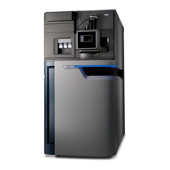
The lock-mass correction, calculated from the lock-spray data, is then applied to the sample data set. You can use the LockSpray source with the following ionization modes: • • APCI • ESCi • nanoSpray SYNAPT G2 MS fitted with LockSpray source Instrument sources... - Page 24 Electrospray ionization In electrospray ionization (ESI), a strong electrical charge is applied to the eluent as it emerges from a nebulizer. The droplets that compose the resultant aerosol undergo a reduction in size (solvent evaporation). As solvent continues to evaporate, the charge density increases until the droplet surfaces eject ions (ion evaporation).
-
Page 25: Nanolockspray Source
Hot gas from the APCI probe passes between the sample cone and the corona pin. Mobile phase molecules rapidly react with ions generated by the corona discharge to produce stable reagent ions. Sample molecules introduced into the mobile phase react with the reagent ions at atmospheric pressure and typically become protonated (in the positive ion mode) or deprotonated (in the negative ion mode). - Page 26 SYNAPT G2 MS fitted with NanoLockSpray source The following options are available for the spraying capillary: • Universal NanoFlow nebulizer sprayer. This option, for flow injection or coupling to nanoACQUITY UPLC, uses a pump to regulate the flow rate as low as 100 nL/min.
-
Page 27: Dual-Mode Ionization Source
The matrix-assisted laser desorption ionization (MALDI) interface enables rapid, tool-free switching between API and MALDI modes. A motorized stage moves the MALDI source into position. The Waters MALDI SYNAPT G2 MS System Operator’s Guide. See also: IntelliStart Fluidics system Overview The IntelliStart Fluidics system is built into the instrument;... -
Page 28: Intellistart Fluidics Physical Layout
For nanoACQUITY UPLC, the valves and pumps that make up the IntelliStart Fluidics system introduce dead volume, which causes unacceptable peak broadening. For this reason, the nanoACQUITY UPLC is plumbed directly to the NanoFlow sprayer using a suitably short piece of silica tubing. -
Page 29: System Operation
The IntelliStart Fluidics system consists of these components: • A sample delivery system, with a rate pump, sample selector valve and diverter valve used for LC and probe connections. • A lock-spray system, with a pump capable of ultra-low flow rates, a lock-spray selector valve, flow sensor, and grounded union. -
Page 30: Ion Optics
Ion optics The mass spectrometer’s ion optics operate as follows: Samples from the LC or instrument’s solvent delivery system are introduced at atmospheric pressure into the ionization source. The ions pass through the sample cone, into the vacuum system. The ions pass through the T-Wave™ ion guide to the quadrupole, where they are filtered according to their mass-to-charge ratio. -
Page 31: Analyzers
Ion optics overview Source T-Wave ion guide LockSpray sprayer Sample spray Quadrupole Pusher Transfer lenses Detector Triwave QuanTof™ mirror Air-cooled turbomolecular pumps Oil-free scroll pump Dual-stage reflectron Analyzers The system uses both quadrupole and time-of-flight (TOF) mass analyzers. You can use the TRAP T-Wave and TRANSFER T-Wave regions of the Triwave device for fragmentation analyses. -
Page 32: Triwave Technology
Triwave technology Triwave technology incorporates three T-Wave devices, each performing a distinct function: • The first T-Wave ion guide (Trap) transfers ions to the second T-Wave ion guide and can function as a collision cell. • The second T-Wave ion guide transfers ions to the third T-Wave ion guide. -
Page 33: Tof Analyzer
TOF analyzer The orthogonal acceleration, dual reflectron geometry of the TOF analyzer provides high resolution and exact mass capabilities. You can operate the analyzer in the modes described in this table. TOF analyzer operating modes Resolving mode Description Sensitivity Maximum sensitivity using single-pass TOF. In this mode, the ions travel from the high-field pusher to the dual-stage reflectron and then to the detector (see the figure on... - Page 34 Single-pass mode Transfer lens High-field pusher Detector Dual-stage reflectron Double-pass mode Transfer lens High-field pusher Ion mirror Detector Dual-stage reflectron 1-16 System Overview...
-
Page 35: Mass Spectrometer Configuration
Using MassLynx and the instrument control software, you control, configure, and operate the instrument. The following processes are performed using the MassLynx software: • Configuring the SYNAPT G2 MS system • Calibrating the SYNAPT G2 MS system • Creating inlet and experiment methods that define operating parameters for an analysis run •... -
Page 36: Leak Sensors
32,000 Da in double-pass mode. Leak sensors Leak sensors in the drip trays of the SYNAPT G2 MS continuously monitor the instrument’s IntelliStart Fluidics system for liquid leaks. A leak sensor stops system flow when it about 1.5 mL of accumulated leaked liquid in its surrounding reservoir. -
Page 37: Controls On The Instrument's Rear Panel
Controls on the instrument’s rear panel The main power switches are on the instrument’s rear panel, (see the figure page B-2). Main power switches AUTO PUMP OVERRIDE RESET AUXILIARY VACUUM ELECTRONICS 200-240V, 50/60Hz, 2kW Power connection Controls on the instrument’s rear panel 1-19... - Page 38 Main power switches Switch Description Pump override Used during servicing, this control must remain in the Auto position at all other times. EPC reset Used to reboot the embedded PC (EPC). The electronics and EPC switches Requirement: must be switched on. Auxiliary This switch provides for future needs by operating a spare power source.
- Page 39 Starting Up and Shutting Down the Mass Spectrometer This chapter describes how to start up, shut down, and reboot the mass spectrometer. Contents Topic Page Starting the mass spectrometer Preparing the IntelliStart Fluidics system Shutting down the mass spectrometer Rebooting the embedded PC...
-
Page 40: Starting Up And Shutting Down The Mass Spectrometer
Starting the mass spectrometer The Waters SYNAPT G2 MS is compatible with the ACQUITY UPLC and nanoACQUITY UPLC systems. If you are not using either of these systems, refer to the documentation relevant to your LC system. Using incompatible solvents can severely damage the Caution: instrument. -
Page 41: Calibration Information
The ACQUITY UPLC system can run at high flow rates. To optimize desolvation, and thus sensitivity, run the ACQUITY UPLC SYNAPT G2 MS UPLC/MS/MS system at appropriate gas flows and desolvation temperatures. Flow rate versus temperature and gas flow... -
Page 42: Preparing The Intellistart Fluidics System
Preparing the IntelliStart Fluidics system For additional information, see “Connecting the liquid waste line” on page B-13. Installing the vials Use standard vials (30 mL) for instrument setup and calibration. To infuse relatively small volumes, use the Low-volume Adaptor Kit (included). The volume of the low-volume vials is 1.5 mL. -
Page 43: Purging The Pump
To install the low-volume vials The vials can be contaminated with biohazardous and/or Warning: toxic materials. Always wear chemical-resistant, powder-free gloves while performing this procedure. If a standard vial is fitted, remove it. Screw the low-volume adaptors into the manifold and finger-tighten them. -
Page 44: Shutting Down The Mass Spectrometer
Shutting down the mass spectrometer You can shut down the system by putting it in Standby mode, by fully shutting it down, or by rebooting it. Putting the mass spectrometer in Standby mode Leave the mass spectrometer in Operate mode except in the following cases, when you must put it in the Standby mode: •... -
Page 45: Rebooting The Embedded Pc
Switch off all the peripherals. Switch off the vacuum, electronics, and the embedded PC and auxiliary breakers located on the rear panel. Rebooting the embedded PC Reboot the embedded PC when either of these conditions applies: • The MassLynx software fails to initialize. •... - Page 46 Starting Up and Shutting Down the Mass Spectrometer...
- Page 47 Configuring the LockSpray Source This chapter explains how to configure the Electrospray source for the following ionization modes: • • APCI • ESCi Contents Topic Page Configuring the LockSpray source Configuring for ESI mode Installing the ESI small bore capillary option Configuring for APCI mode 3-14 Configuring for ESCi mode...
-
Page 48: Configuring The Lockspray Source
If you intend using the small-bore capillary option, fit the capillary to the probe first (see page 3-8). For more information on using ESI mode, see the SYNAPT G2 MS system online Help. Installing the ESI probe Required materials •... - Page 49 Prepare the instrument for working on the source (see page 5-7). The ESI probe tip is sharp. To avoid puncture wounds, Warning: handle the ESI probe with care. Remove the protective sleeve, if fitted, from the ESI probe tip. Carefully slide the ESI probe into the hole in the probe adjuster assembly, ensuring that the probe location dowel aligns with the location hole in the probe adjuster assembly.
- Page 50 ESI probe, mounted on the LockSpray source enclosure Vernier probe adjuster ESI probe Probe locking ring ESI probe cable High voltage connector Source window Source enclosure release TP03128 To avoid nitrogen leakage, fully tighten the probe locking Caution: ring. Tighten the probe locking ring to secure the probe in place. Connect the ESI probe’s cable to the high voltage connector.
- Page 51 Source interface door Source interface door. To avoid electric shock, do not use stainless steel tubing Warning: to connect the diverter valve to the ESI probe; use the PEEK tubing supplied with the instrument. Using PEEK tubing greater than or equal to 0.004-inch ID, connect port 2 (the top port) of the diverter valve to the ESI probe.
- Page 52 • At the diverter valve, use a long "finger tight" PEEK fitting. • At the probe, use a PEEK nut and ferrule, finger tightened, to connect to the PEEK union. Tubing connection between the diverter valve and the ESI probe (The other connections are omitted for clarity.) Long "finger tight"...
-
Page 53: Removing The Esi Probe
Removing the ESI probe Required materials Chemical-resistant, powder-free gloves To remove the ESI probe The LC system connections, ESI probe, and source can Warning: be contaminated with biohazardous and/or toxic materials. Always wear chemical-resistant, powder-free gloves while performing this procedure. To avoid electric shock, prepare the instrument for work Warning: performed on its source before commencing this procedure. -
Page 54: Installing The Esi Small Bore Capillary Option
Installing the ESI small bore capillary option The ESI small bore capillary option is for use with 1-mm UPLC columns running at flowrates of 100 to 200 µL/min. The materials needed for this task are in the Small-Bore Capillary kit. To avoid damage from excessive pressure, do not exceed flow Caution: rates of 200 µL/min through the ESI probe when using the small-bore... - Page 55 To install the capillary The probe and source components can be contaminated Warning: with biohazardous and/or toxic materials. Always wear chemical-resistant, powder-free gloves while performing this procedure. The ESI probe tip is sharp. To avoid puncture wounds, handle Warning: the probe with care. Remove the existing capillary (see page 5-59).
- Page 56 Using the needle-nose pliers, slide the UNF coupler, PTFE liner sleeve, and a ferrule onto the capillary. UNF coupler Ferrule PTFE liner sleeve Insert the capillary in the PEEK union, and ensure that it is fully seated. Finger-tighten the UNF coupling into the PEEK union. Gently tug on the capillary, testing to ensure that it stays in place.
- Page 57 To avoid high-pressure jet spray, wear safety goggles Warning: when performing the leak test. 12. Perform a leak test by attaching the free end of the PEEK tubing to an LC pump and pumping mobile phase through it, at 200 µL/min. •...
- Page 58 19. Fit the new metal gasket to the probe tip. Metal gasket 20. Fit the probe tip over the capillary, and screw the tip onto the probe assembly. To avoid gas leakage, fully tighten the probe tip. Caution: 21. Using the 10-mm wrench, tighten the probe tip. 10-mm wrench Probe tip 22.
- Page 59 23. Fit the end cover and gasket to the probe assembly. Nebulizer adjuster knob Gasket End cover 24. Using the combined 2.5-mm Allen wrench, fit and tighten the 3 screws that retain the end cover. End-cover retaining screws Installing the ESI small bore capillary option 3-13...
-
Page 60: Configuring For Apci Mode
Configuring for APCI mode To operate in APCI mode, you must fit the APCI probe and corona pin to the LockSpray source enclosure. For more information on using APCI mode, see the SYNAPT G2 MS system online Help. Installing the APCI probe Required materials •... - Page 61 Prepare the instrument for work performed on its source (see page 5-7). Carefully slide the APCI probe into the hole in the probe adjuster assembly, ensuring that the probe location dowel aligns with the location hole in the probe adjuster assembly. APCI probe location dowel Location hole in the probe adjuster assembly...
- Page 62 Tighten the probe locking ring to secure the probe in place. APCI probe mounted on the source enclosure Vernier probe adjuster APCI probe Probe locking ring Vertical probe adjuster Source window Source enclosure release TP03128 Slide open the instrument’s source interface door (see the figure on page 3-5).
- Page 63 • At the diverter valve, use a long "finger tight" PEEK fitting. • At the probe, use a PEEK nut and ferrule, finger tightened, to connect to the PEEK union. Tubing connection between the diverter valve and the APCI probe (The other tubing connections are omitted for clarity.) Long "finger tight"...
-
Page 64: Installing The Corona Pin In The Source
Installing the corona pin in the source Install the corona pin according to the procedure on page 5-12. Removing the corona pin from the source Remove the corona pin according to the procedure on page 5-14. Removing the APCI probe Required materials Chemical-resistant, powder-free gloves To remove the APCI probe... -
Page 65: Configuring For Esci Mode
ESI and ESCi modes, facilitating data acquisition in ESI and ESCi modes in parallel. For more information on using dual ESI and ESCi modes, see the SYNAPT G2 MS system online Help. When fitting the ESI probe to the LockSpray source enclosure, follow the procedure on page 3-2. - Page 66 3-20 Configuring the LockSpray Source...
- Page 67 Configuring the NanoLockSpray source The Waters NanoLockSpray™ dual, electrospray, ion source enables the optimized co-introduction of sample and lock-mass reference compound directly into the ion source. At low flow rates, this feature provides authenticated, exact-mass measurement in both MS and MS/MS modes.
-
Page 68: Configuring The Nanolockspray Source
Overview of the NanoLockSpray source NanoLockSpray source LockSpray sprayer inlet NanoLockSpray reference probe Camera Camera focussing ring Z-position adjuster Sprayer safety cover X-position adjuster Thumbscrew (on left-hand side of sprayer platform) TP03199 Sprayer platform adjuster assembly Y-position adjuster Thumbscrew The NanoLockSpray source enclosure holds two nanospray sprayers positioned orthogonally with respect to one another. -
Page 69: Sample Sprayer
Schematic of the NanoLockSpray source LockSpray sprayer Sample sprayer Baffle Sample cone Spray indexing permits acquiring sample and lock-spray data in separate data channels, and the baffle design ensures negligible cross-talk between the two sprays. The lock-spray data are used to calculate a correction factor for the mass-scale calibration, which is then applied to the sample data, providing exact-mass information. -
Page 70: Nanoflow Gas Supply
The Universal NanoFlow sprayer is installed as standard equipment on the NanoLockSpray source. For installation and maintenance details, see the Waters Universal NanoFlow Sprayer Installation and Maintenance Guide (part number 71500110107). To select the NanoLockSpray source, from the Tune window, click Source >... -
Page 71: Deploying The Sprayer Platform Adjuster Assembly
NanoLockSpray source configuration Sprayer type Used for Universal NanoFlow nebulizer Flow injection or for coupling to sprayer nanoACQUITY UPLC with regulated flow rates down to 100 nL/min. Borosilicate glass capillary Extremely low flow rates (less than NanoFlow (see page 4-8). 100 nL/min). -
Page 72: Adjusting The Sprayer Tip Position
To move the sprayer platform into the source To avoid electrical shock, ensure the safety cover is in place Warning: over the sprayer. Confirm that the sprayer’s safety cover is installed (see the figure on page 4-2). Pull out the side thumbscrew, and push the sprayer platform into the source. -
Page 73: Setting Up The Camera
Setting up the camera To set up the camera On the Tune window click Source > Nanoflow. Click to open the Camera Control dialog box. Camera Control view of sprayers and sample cone Sample cone Baffle Sample spray Sample sprayer Rotate the camera’s focusing ring to focus on the sample sprayer (see the figure on page... -
Page 74: Optional Glass Capillary Sprayer
Optional glass capillary sprayer The glass capillary sprayer is designed for use with metal-coated borosilicate glass capillaries, which allow extremely low flow rates (less than 100 nL/min). The capillaries are used for one sample only and must then be discarded. To use the glass capillary sprayer, you must complete the following procedures: •... -
Page 75: Fitting And Loading The Glass Capillary
Place the sprayer (with gas line fitted) on the platform, and secure it with the thumbscrew. Refit the safety cover. Fitting and loading the glass capillary Required materials • Chemical-resistant, powder-free gloves ® • Fused silica syringe needle or a GELoader To fit and load the glass capillary The source components can be contaminated with Warning:... - Page 76 Carefully remove the capillary from its case by lifting it vertically while pressing down on the foam with two fingers. Over the square-cut end of the capillary, pass first the knurled nut, then approximately 5 mm of conductive elastomer, and finally the union. Union Knurled nut Elastomer...
- Page 77 To optimize the glass capillary sprayer To avoid eye injuries, always wear eye protection when cutting Warning: fused silica. To avoid injury from trace chemicals on the probe, always Warning: wear chemical-resistant, powder-free gloves. Set the NanoFlow gas pressure to 0.3 bar and the cone gas to 40 L/h. Ascertain that sample is flowing by observing a droplet on the tip.
- Page 78 Return the sprayer to its previous position. Ascertain that sample is flowing by observing a droplet on the tip. If you cannot observe a droplet, increase the pressure briefly, up to Tip: a maximum of 1.5 bar, and then return the pressure to 0.3 bar. If you observe a droplet, continue the procedure at step If you do not observe a droplet, repeat...
-
Page 79: Maintenance Procedures
Maintenance Procedures This chapter provides the maintenance guidelines and procedures necessary to maintain the instrument’s performance. Keep to a maintenance schedule, and perform maintenance as required and described in this chapter. Contents Topic Page Maintenance schedule Spare parts Troubleshooting using Connections Insight Safety and handling Preparing the instrument for work performed on its source Removal and refitting of the source enclosure... - Page 80 Contents(continued) Topic Page Replacing the NanoLockSpray reference probe capillary 5-78 Cleaning or replacing the corona pin 5-83 Replacing the APCI probe heater 5-84 Replacing the ion block source heater 5-87 Replacing the LockSpray source assembly seals 5-91 Replacing the mass spectrometer’s air filter 5-95 Replacing the IntelliStart Fluidics tubing 5-98...
-
Page 81: Maintenance Schedule
Maintenance schedule The following table lists periodic maintenance schedules that ensure optimum instrument performance. Maintenance schedule Procedure Frequency For information... Clean the instrument case. As required. page 5-18. Empty the nitrogen exhaust Check daily, empty as page 5-19. trap bottle. required. -
Page 82: Spare Parts
IntelliStart Fluidics system components. Spare parts Replace only the parts mentioned in this document. For spare parts details, see the Waters Quality Parts Locator on the Waters Web site’s Services/Support page. Maintenance Procedures... -
Page 83: Troubleshooting Using Connections Insight
Connections Insight is an “intelligent” device management (IDM) Web service that enables Waters to provide proactive service and support for the ACQUITY UPLC system. Before you can use Connections Insight, a Waters technician must install its service agent software on your MassLynx workstation. -
Page 84: Safety And Handling
Safety and handling Bear in mind the following safety considerations when performing maintenance procedures: The instrument components can be contaminated with Warning: biologically hazardous materials. Always wear chemical-resistant, powder-free gloves while handling the components. To prevent injury, always observe Good Laboratory Practices Warning: when handling solvents, changing tubing, or operating the instrument. -
Page 85: Preparing The Instrument For Work Performed On Its Source
In the Instrument Console, click Stop Flow to stop the LC flow or, if column flow is required, divert the LC flow to waste as follows: In the Instrument Console system tree, expand SYNAPT G2 Detector, Interactive Fluidics. Click Control Select Waste as the flow state. -
Page 86: Removal And Refitting Of The Source Enclosure
Removal and refitting of the source enclosure The following procedures apply to both the standard and optional source enclosures. You must remove the LockSpray or NanoLockSpray source enclosure from the instrument before performing certain maintenance procedures or fitting the optional dual-mode APPI/APCI source. Removing the source enclosure from the instrument Required materials Chemical-resistant, powder-free gloves... - Page 87 Disconnect the source enclosure cables from the instrument’s connectors. The corona pin tip is sharp. To avoid puncture wounds, Warning: take great care while working with the source enclosure open if a corona pin is fitted. To avoid damaging the sample inlet when removing a Caution: NanoLockSpray source enclosure, move the sprayer platform out of the source enclosure before opening it (see...
- Page 88 Store the cables neatly by plugging them into the cable-storage positions on the rear of the source enclosure. Cable storage positions 5-10 Maintenance Procedures...
-
Page 89: Fitting The Source Enclosure To The Instrument
Fitting the source enclosure to the instrument Required materials Chemical-resistant, powder-free gloves To fit the source enclosure to the instrument The source components can be contaminated with Warning: biohazardous and/or toxic materials. Always wear chemical-resistant, powder-free gloves while performing this procedure. -
Page 90: Installing And Removing The Corona Pin
Installing and removing the corona pin For APCI, ESCi, and dual-mode APPI/APCI operation, a corona pin must be fitted to the source. Installing the corona pin in the source Required materials Chemical-resistant, powder-free gloves To install the corona pin in the source The LC system connections, ESI probe, and source can Warning: be contaminated with biohazardous and/or toxic materials. - Page 91 Corona pin mounting contact Corona pin mounting contact blanking plug TP03130 Fit the corona pin to the corona pin mounting contact. Ensure that the corona pin is securely mounted and that Requirement: its tip aligns with the sample cone orifice. Corona pin Corona pin TP03130...
-
Page 92: Removing The Corona Pin From The Source
Close the source enclosure. Look through the source window, and using the vernier probe adjuster (see the figure on page 3-4), position the ESI probe tip so that it is pointing, approximately, midway between the tips of the sample cone and corona pin. -
Page 93: Operating The Source Isolation Valve
Operating the source isolation valve You must close the source isolation valve to isolate the source from the instrument vacuum system for certain maintenance procedures. Required materials Chemical-resistant, powder-free gloves To close the source isolation valve before starting a maintenance procedure The source components can be contaminated with Warning: biohazardous and/or toxic materials. - Page 94 Close the source isolation valve by moving its handle counterclockwise, to the vertical position. Isolation valve handle in closed position TP03130 To open the source isolation valve after completing a maintenance procedure The source components can be contaminated with Warning: biohazardous and/or toxic materials.
-
Page 95: Removing O-Rings And Seals
Open the source isolation valve by moving its handle clockwise to the horizontal position. Isolation valve handle in open position TP03130 Close the source enclosure. Removing O-rings and seals When performing certain maintenance procedures, you must remove O-rings or seals from instrument components. An O-ring removal kit accompanies the instrument. -
Page 96: Cleaning The Mass Spectrometer Case
To remove an O-ring When removing an O-ring or seal from a component, be careful Caution: not to scratch the component with the removal tool. Use the tools as aids to pull the O-ring or seal from its groove. If the O-ring or seal is not going to be reused, you can use the forked end Tip: of tool 1 to impale the O-ring or seal, and aid its removal. -
Page 97: Emptying The Nitrogen Exhaust Trap Bottle
Emptying the nitrogen exhaust trap bottle Inspect the nitrogen exhaust trap bottle in the instrument exhaust line daily, and empty it before it is more than approximately 10% full. Nitrogen exhaust trap bottle From instrument To laboratory pilot valve port exhaust port From instrument exhaust connection... - Page 98 To empty the nitrogen exhaust trap bottle In the Instrument Console, click Stop Flow Pull the source enclosure release (located at the bottom, right-hand side) outwards, and swing open the enclosure. The waste liquid in the nitrogen exhaust trap Warning: bottle comprises ACQUITY UPLC solvents and samples.
-
Page 99: Cleaning The Source Components
Cleaning the source components Clean the sample cone and cone gas nozzle (see page 5-21) when these conditions apply: • The sample cone and cone gas nozzle are visibly fouled. • LC and sample-related causes for decreased signal intensity have been dismissed. - Page 100 To remove the sampling cone assembly from the source The source components can be contaminated with Warning: biohazardous and/or toxic materials. Always wear chemical-resistant, powder-free gloves while performing this procedure. To avoid electric shock, ensure that the instrument is in Warning: Standby mode before commencing this procedure.
-
Page 101: Disassembling The Sampling Cone Assembly
Do not open the isolation valve at any time when the Caution: sampling cone assembly has been removed from the ion block assembly. Slide the sampling cone assembly out of the ion block assembly. Combined 2.5-mm Allen wrench and cone extraction tool Ion block assembly... - Page 102 Retrieve the combined 2.5-mm Allen wrench and cone extraction tool from its storage location on the source adaptor housing. On the combined 2.5-mm Allen wrench and cone extraction tool, slide the collar to the end of the tool. Collar Insert the collar in the sample cone. 5-24 Maintenance Procedures...
- Page 103 The sample cone is fragile. Never place it on its tip; Caution: always place it on its flanged base. Rotate and lift the tool and collar to remove the sample cone from the cone gas nozzle. Sample cone Cone gas nozzle Remove the sample cone from the combined 2.5-mm Allen wrench and cone extraction tool.
-
Page 104: Cleaning The Sample Cone And Cone Gas Nozzle
The O-ring can be contaminated with Warning: biohazardous and/or toxic materials. Dispose of it according to local environmental regulations. If the O-ring shows signs of deterioration or damage, dispose of it in accordance with local environmental regulations. Unscrew and remove the PEEK cone gas nozzle handle from the cone gas nozzle. - Page 105 To clean the sample cone and cone gas nozzle The sample cone and cone gas nozzle can be Warning: contaminated with biohazardous and/or toxic materials. Always wear chemical-resistant, powder-free gloves while performing this procedure. Formic acid is extremely corrosive and toxic. Work with Warning: extreme care.
-
Page 106: Assembling The Sampling Cone Assembly
Inspect each component for persisting contamination. If contamination is present, do as follows: Using the wash bottle containing 1:1 methanol/water, rinse the component over the large beaker. Blow-dry the component with inert, oil-free gas. Inspect each component for persisting contamination. If contamination is present, repeat the cleaning Requirement: procedure. -
Page 107: Fitting The Sampling Cone Assembly To The Source
Carefully fit the sample cone into the cone gas nozzle. Fit the O-ring into the groove created between the sample cone and cone gas nozzle. Fit a new O-ring, if necessary. Requirement: Fitting the sampling cone assembly to the source Required materials Chemical-resistant, powder-free gloves To fit the sampling cone assembly to the source... - Page 108 Ensure that the source isolation valve is in the closed position (see page 5-15). Hold the sampling cone assembly so that the cone gas nozzle handle is oriented horizontally and at the top, and then slide the sampling cone assembly into the ion block assembly. Ion block assembly TP03132 Sampling cone assembly...
-
Page 109: Cleaning The Extraction Cone
Cleaning the extraction cone Clean the ion block and extraction cone if cleaning the sample cone and cone gas nozzle fails to increase signal sensitivity. You must remove the ion block assembly from the source assembly to clean the extraction cone. Removing the ion block assembly from the source assembly Required materials •... - Page 110 Using the combined 2.5-mm Allen wrench and cone extraction tool, unscrew the 4 captive screws that secure the ion block assembly. Ion block assembly securing screws TP03130 Remove the ion block assembly from the PEEK ion block support. PEEK ion block support Ion block assembly TP03130...
-
Page 111: Removing The Extraction Cone From The Ion Block
Removing the extraction cone from the ion block Required materials • Chemical-resistant, powder-free gloves • Combined 2.5-mm Allen wrench and cone extraction tool To remove the extraction cone from the ion block The ion block components can be contaminated with Warning: biohazardous and/or toxic materials. -
Page 112: Cleaning The Extraction Cone
Caution: • Take great care not to damage the extraction cone aperture when removing the extraction cone from the ion block. • The extraction cone is fragile. Never place it on its tip; always place it on its flanged base. Remove the extraction cone from the ion block. - Page 113 • Ultrasonic bath. • Source of oil-free, inert gas (for example, nitrogen) for drying (air-drying optional). • Wash bottle containing HPLC-grade (or better) 1:1 methanol/water. • Large beaker. To clean the extraction cone The extraction cone can be contaminated with Warning: biohazardous and/or toxic materials.
-
Page 114: Fitting The Extraction Cone To The Ion Block
To avoid recontaminating the extraction cone, wear Caution: clean, chemical-resistant, powder-free gloves for the rest of this procedure. Carefully remove the extraction cone from the vessel, and blow-dry it using inert, oil-free gas. Inspect the extraction cone for persisting contamination. If contamination is present, do as follows: Using the wash bottle containing 1:1 methanol/water, rinse the extraction cone over the large beaker. -
Page 115: Fitting The Ion Block Assembly To The Source Assembly
Fit the extraction cone handle insulator to the extraction cone handle. Fit the extraction cone to the ion block. Rotate the 2 PEEK extraction cone retainer clips to secure the extraction cone, and then, using the combined 2.5-mm Allen wrench and cone extraction tool, tighten the screws that secure the retainer clip. -
Page 116: Cleaning The Ion Block Assembly
Cleaning the ion block assembly Clean the ion block assembly if cleaning the sample cone, cone gas nozzle, and extraction cone fails to increase signal sensitivity. Disassembling the source ion block assembly Required materials • Chemical-resistant, powder-free gloves • Combined 2.5-mm Allen wrench and cone extraction tool •... - Page 117 Remove the ion block assembly from the source assembly (see page 5-31). Ensure that the isolation valve is closed. Isolation valve handle in closed position Sampling cone assembly retaining blocks Cone gas nozzle handle Grasp the cone gas nozzle handle, and use it to rotate the sampling cone assembly through 90 degrees.
- Page 118 Using the combined 2.5-mm Allen wrench and cone extraction tool, loosen the 2 captive screws that secure the ion block cover plate. Ion block cover plate securing screw Ion block cover plate Remove the ion block cover plate. Grasp the isolation valve and pull it out of the ion block. Isolation valve O-ring 5-40...
- Page 119 Using the O-ring removal kit, carefully remove the isolation valve O-ring (see page 5-17). The isolation valve O-ring can be contaminated Warning: with biohazardous and/or toxic materials. Dispose of it according to local environmental regulations. If the isolation valve O-ring shows signs of deterioration or damage, dispose of it in accordance with local environmental regulations.
- Page 120 12. Holding the PEEK terminal block gently, use the needle-nose pliers to gently grasp the heat-shrink tubing on the heater cartridge assembly and carefully slide it and the PEEK terminal block out of the ion block. Heat-shrink tubing PEEK terminal block Heater cartridge assembly 13.
- Page 121 14. Using the O-ring removal kit, carefully remove the cone gas O-ring from the ion block. The cover seal and cone gas O-ring can be Warning: contaminated with biohazardous and/or toxic materials. Dispose of them according to local environmental regulations. 15.
- Page 122 18. Using the combined 2.5-mm Allen wrench and cone extraction tool, remove the captive screws securing the 2 PEEK extraction cone retainer clips. Securing screw Retainer clip Extraction cone Caution: • Take great care not to damage the extraction cone aperture when removing the extraction cone from the ion block.
-
Page 123: Cleaning The Ion Block Components
20. Remove the extraction cone handle insulator from the extraction cone handle. 21. Remove the extraction cone seal from the ion block. Extraction cone seal Cleaning the ion block components Required materials • Chemical-resistant, powder-free gloves. • Appropriately sized glass vessels in which to completely immerse components when cleaning. - Page 124 To clean the ion block components The ion block components can be contaminated with Warning: biohazardous and/or toxic materials. Always wear chemical-resistant, powder-free gloves while performing this procedure. Formic acid is extremely corrosive and toxic. Work with Warning: extreme care, use a fume hood and suitable protective equipment. Immerse the ion block and isolation valve in separate glass vessels containing 1:1 methanol/water.
-
Page 125: Assembling The Source Ion Block Assembly
The components can be contaminated with Warning: biohazardous and/or toxic materials. Dispose of them according to local environmental regulations. Inspect each component for persisting contamination. If contamination is present, repeat the cleaning Requirement: procedure. If contamination is still present, dispose of the component, and obtain a new one before reassembling the sampling cone assembly. - Page 126 Using the combined 2.5-mm Allen wrench and cone extraction tool, tighten the captive screw securing each extraction cone retainer clip to the ion block. Fit the blanking plug O-ring to the ion block blanking plug. Fit a new O-ring, if necessary. Requirement: Fit the blanking plug to the ion block, and finger-tighten it.
-
Page 127: Cleaning The Source T-Wave Ion Guide Assembly
17. Fit the ion block cover plate to the ion block assembly, and then, using the combined 2.5-mm Allen wrench and cone extraction tool, tighten the 2 captive screws that secure the ion block cover plate. 18. Hold the sampling cone assembly so that the cone gas nozzle handle is oriented horizontally and at the top, and then slide the sampling cone assembly into the ion block assembly. - Page 128 Remove the ion block assembly from the PEEK ion block support (see page 5-31). Using the 3-mm Allen wrench, unscrew and remove the 4 screws securing the PEEK ion block support to the source adaptor housing. Source adaptor housing PEEK ion block support T-Wave ion guide...
-
Page 129: Disassembling The T-Wave Ion Guide Assembly
Disassembling the T-Wave ion guide assembly Required materials • Chemical-resistant, powder-free gloves • Jeweler’s screwdriver To disassemble the T-Wave ion guide assembly The T-Wave ion guide components can be Warning: contaminated with biohazardous and/or toxic materials. Always wear chemical-resistant, powder-free gloves while performing this procedure. -
Page 130: Cleaning The T-Wave Ion Guide Assembly Aperture Plate
Using the jeweler’s screwdriver, remove the 3 screws securing the aperture plate to the assembly. Remove the aperture plate from the assembly. Do not further disassemble the T-Wave ion guide. Requirement: Cleaning the T-Wave ion guide assembly aperture plate Required materials •... - Page 131 • Appropriately-sized glass vessel in which to completely immerse the T-Wave ion guide when cleaning Use only glassware not previously cleaned with Requirement: surfactants. • HPLC-grade (or better) 1:1 methanol/water • Ultrasonic bath • Source of oil-free, inert gas (for example, nitrogen) for drying (air-drying optional) To clean the T-Wave ion guide The T-Wave ion guide can be contaminated with...
-
Page 132: Assembling The T-Wave Ion Guide Assembly
Assembling the T-Wave ion guide assembly Required materials • Chemical-resistant, powder-free gloves • Jeweler’s screwdriver To assemble the T-Wave ion guide assembly To avoid recontaminating the T-Wave ion guide assembly, Caution: wear clean, chemical-resistant, powder-free gloves during this procedure. Fit the aperture plate to the T-Wave ion guide assembly. Using the jeweler’s screwdriver, fit and tighten the 3 screws securing the aperture plate to the T-Wave ion guide assembly. -
Page 133: Replacing The Esi Probe Tip And Gasket
To fit the T-Wave ion guide assembly and PEEK ion block support to the source To avoid recontaminating the source, wear clean, Caution: chemical-resistant, powder-free gloves during this procedure. To avoid damage when fitting the hexapole assembly into the Caution: source adaptor housing: •... -
Page 134: Removing The Esi Probe Tip And Gasket
Removing the ESI probe tip and gasket Required materials • Chemical-resistant, powder-free gloves • 7-mm wrench • 10-mm wrench To remove the ESI probe tip and gasket The probe and source components can be contaminated Warning: with biohazardous and/or toxic materials. Always wear chemical-resistant, powder-free gloves while performing this procedure. - Page 135 If the probe tip is difficult to remove, use the 7-mm wrench in Tip: conjunction with the 10-mm wrench. 7-mm wrench 10-mm wrench Probe tip Remove the metal gasket from the probe tip. Metal gasket The probe tip and metal gasket can be Warning: contaminated with biohazardous and/or toxic materials.
-
Page 136: Fitting The Esi Probe Tip And Gasket
Fitting the ESI probe tip and gasket Required materials • Chemical-resistant, powder-free gloves • 10-mm wrench • New metal gasket To fit the ESI probe tip and gasket The probe and source components can be contaminated Warning: with biohazardous and/or toxic materials. Always wear chemical-resistant, powder-free gloves while performing this procedure. -
Page 137: Replacing The Esi Probe Sample Capillary
Replacing the ESI probe sample capillary Replace the stainless steel sample capillary in the ESI probe if it becomes blocked and cannot be cleared, or if it becomes contaminated or damaged. Removing the existing capillary Required materials • Chemical-resistant, powder-free gloves •... - Page 138 Using the combined 2.5-mm Allen wrench and cone extraction tool, remove the 3 probe end cover retaining screws. End cover retaining screws Remove the end cover and gasket from the probe assembly. Nebulizer adjuster knob Gasket End cover Unscrew and remove the nebulizer adjuster knob. 5-60 Maintenance Procedures...
- Page 139 Using the 10-mm wrench, remove the probe tip. 10-mm wrench Probe tip If the probe tip is difficult to remove, use the 7-mm wrench in Tip: conjunction with the 10-mm wrench. 7-mm wrench 10-mm wrench Probe tip Replacing the ESI probe sample capillary 5-61...
- Page 140 Remove the metal gasket from the probe tip. Metal gasket The metal gasket can be contaminated with Warning: biohazardous and/or toxic materials. Dispose of it according to local environmental regulations. Dispose of the metal gasket in accordance with local environmental regulations.
- Page 141 10. Unscrew and remove the knurled collar from the UNF coupling. PEEK union UNF coupling Locknut Knurled collar Conductive sleeve 11. Remove the knurled collar and conductive sleeve from the capillary. 12. Using the 7-mm wrench, loosen the locknut. Use the 8-mm wrench to steady the UNF coupling when loosening Tip: the locknut.
-
Page 142: Installing The New Capillary
Installing the new capillary Required materials • Chemical-resistant, powder-free gloves • Combined 2.5-mm Allen wrench and cone extraction tool • 10-mm wrench • Needle-nose pliers • LC pump • HPLC-grade (or better) 1:1 acetonitrile/water • Capillary • Ferrule • Seal •... - Page 143 Using the sharp knife or PEEK tubing cutter, cut an approximately 60-cm (24-inches) length of red PEEK tubing squarely (that is, perpendicular to its horizontal axis). Insert one end of the red PEEK tubing in the probe inlet connector, and screw the connector, finger-tight, into the PEEK union.
- Page 144 To avoid high-pressure liquid jet spray, wear safety Warning: goggles when performing the leak test. 11. Perform a leak test by attaching the free end of the PEEK tubing to an LC pump and pumping 50:50 acetonitrile/water through it, at 1 mL/min. •...
-
Page 145: Cleaning The Apci Probe Tip
See the mass spectrometer’s online Help for further details. To clean the APCI probe tip On the Instrument Console system tree, click SYNAPT G2 > Manual optimization. On the manual optimization page, click to stop the liquid flow. -
Page 146: Replacing The Apci Probe Sample Capillary
Wait 10 minutes. The high APCI probe heater temperature removes any Rationale: chemical contamination from the probe tip. Click Standby Replacing the APCI probe sample capillary Replace the stainless steel sample capillary in the APCI probe if it becomes blocked and you cannot clear it, or if it becomes contaminated or damaged. Removing the existing capillary Required materials •... - Page 147 Using the combined 2.5-mm Allen wrench and cone extraction tool, remove the 3 probe end cover retaining screws. End cover retaining screws Remove the end cover and gasket. Nebulizer adjuster knob Gasket End cover Unscrew and remove the nebulizer adjuster knob. Replacing the APCI probe sample capillary 5-69...
- Page 148 Remove the PEEK union/UNF coupling assembly and capillary from the probe. PEEK union/UNF coupling assembly Capillary Locknut Using the 7-mm wrench, loosen the locknut. Unscrew the PEEK union from the UNF coupling (this connection is finger-tight only). Ferrule Remove the ferrule from the capillary. 10.
-
Page 149: Installing The New Capillary
Installing the new capillary Required materials • Chemical-resistant, powder-free gloves • Needle-nose pliers • 7-mm wrench • Combined 2.5-mm Allen wrench and cone extraction tool • Red PEEK tubing • LC pump • HPLC-grade (or better) 1:1 acetonitrile/water • Capillary •... - Page 150 Using the sharp knife or PEEK tubing cutter, cut an approximately 60 cm (24 inches) piece of red PEEK tubing squarely (that is, perpendicular to its horizontal axis). Insert one end of the red PEEK tubing in the probe inlet connector, and screw the connector, finger-tight, into the PEEK union.
- Page 151 Perform a leak test by attaching the free end of the PEEK tubing to an LC pump and pumping 50:50 acetonitrile/water through it, at 1 mL/min. • If leakage occurs, disassemble and remake the connection, and repeat the leak test. •...
-
Page 152: Replacing The Lockspray Probe Capillary
20. Replace the combined 2.5-mm Allen wrench and cone extraction tool in its storage location on the source adaptor housing. Caution: • When handling the probe heater, take great care to grip the heater so as not to damage its electrical wiring. •... - Page 153 To remove the existing capillary Prepare the instrument for working on the source (see page 5-7). The probe and source can be hot. To avoid burn injuries, Warning: take great care while working with these components. The ESI probe tip is sharp. To avoid puncture wounds, if Warning: an ESI probe is fitted to the source, remove the probe before continuing with this procedure.
- Page 154 Rotate the LockSpray sprayer assembly clockwise through 90º, and remove it from the LockSpray sprayer support assembly. LockSpray sprayer support assembly LockSpray sprayer assembly Using the 4-mm wrench, unscrew and remove the LockSpray probe tip from the LockSpray sprayer assembly. Using the 7-mm wrench, unscrew the compression fitting on the rear of the LockSpray sprayer assembly.
-
Page 155: Installing The New Capillary
Installing the new capillary Required materials • Chemical-resistant, powder-free gloves • 4-mm wrench • 7-mm wrench • New capillary To install the new capillary Fit the capillary into the liner tubing. Fit the liner tubing and capillary to the LockSpray sprayer assembly. Using the 4-mm wrench, fit and tighten the LockSpray probe tip to the LockSpray sprayer assembly. -
Page 156: Replacing The Nanolockspray Reference Probe Capillary
Replacing the NanoLockSpray reference probe capillary Replace the NanoLockSpray reference probe TaperTip™ or capillary if it is irreversibly blocked, or if it is contaminated or damaged. Removing the NanoLockSpray reference probe Required materials • Chemical-resistant, powder-free gloves • Combined 2.5-mm Allen wrench and cone extraction tool •... - Page 157 Using the combined 2.5-mm Allen wrench and cone extraction tool, unscrew the 3 fixing screws from the top of the NanoLockSpray reference probe. Fixing screw NanoLockSpray reference probe The NanoLockSpray reference probe tip consists of 5 cm Warning: of exposed, fused-silica TaperTip, which is sharp and fragile. To avoid puncture wounds, handle the probe with care.
-
Page 158: Installing The New Tapertip And Capillary
Unscrew the capillary PEEK coupler, and remove the fused-silica capillary from the union. 10. Where appropriate, remove the protective PEEK sleeve from the fused silica capillary for reuse. The fused silica capillary can be contaminated Warning: with biohazardous and/or toxic materials. Dispose of it according to local environmental regulations. - Page 159 To install the new TaperTip and capillary On the NanoLockSpray reference probe assembly, screw the pin-plug capillary locator into the end of the union block. NanoLockSpray eference probe Pin-plug capillary locator Thread the capillary through the body of the NanoLockSpray reference probe.
- Page 160 The NanoLockSpray reference probe tip is an exposed, Warning: fused-silica TaperTip which is sharp and fragile. To avoid puncture wounds, handle the probe with care. Ensure that you are inserting the square-cut end of the Caution: TaperTip into the union and not the tapered tip. Align the PEEK coupler in the end of the union and slide the TaperTip into the union until it butts against the fused-silica capillary.
-
Page 161: Cleaning Or Replacing The Corona Pin
Cleaning or replacing the corona pin Required materials • Chemical-resistant, powder-free gloves • Needle-nose pliers • HPLC-grade (or better) methanol • Lint-free tissue • Lapping film • New corona pin To clean or replace the corona pin The probe and source components can be contaminated Warning: with biohazardous and/or toxic materials. -
Page 162: Replacing The Apci Probe Heater
Replacing the APCI probe heater Replace the APCI probe heater it fails to heat the probe. Removing the APCI probe heater Required materials Chemical-resistant, powder-free gloves To remove the APCI probe heater The probe and source components can be contaminated Warning: with biohazardous and/or toxic materials. - Page 163 To avoid damaging the probe heater’s electrical Caution: connections, do not twist the heater when removing it from the probe assembly. Gripping the probe heater as shown, carefully pull it off the probe assembly. The probe heater can be contaminated with Warning: biohazardous and/or toxic materials.
-
Page 164: Fitting The New Apci Probe Heater
Fitting the new APCI probe heater Required materials • Chemical-resistant, powder-free gloves • APCI probe heater To fit the new APCI probe heater Take great care not to damage the probe heater’s Caution: electrical connections, the capillary sleeve, or capillary when fitting the heater over the capillary sleeve. -
Page 165: Replacing The Ion Block Source Heater
Replacing the ion block source heater Replace the ion block source heater if it fails to heat the ion block. Required materials • Chemical-resistant, powder-free gloves • Needle-nose pliers • Combined 2.5-mm Allen wrench and cone extraction tool • Ion block source heater To replace the ion block source heater The ion block assembly can be contaminated with Warning:... - Page 166 Using the combined 2.5-mm Allen wrench and cone extraction tool, loosen the 2 captive screws securing the ion block cover plate. Ion block cover plate securing screw Ion block cover plate Remove the ion block cover plate. Using the combined 2.5-mm Allen wrench and cone extraction tool, remove the 2 screws securing the heater wires to the PEEK terminal block.
- Page 167 Using the needle-nose pliers, carefully swing the ring terminal tags out of the terminal block. Ring terminal tag Using the needle-nose pliers, gently grasp the heat-shrink tubing on the heater cartridge assembly and slide the assembly out of the ion block. Heat-shrink tubing Heater cartridge assembly Replacing the ion block source heater...
- Page 168 The heater cartridge assembly can be Warning: contaminated with biohazardous and/or toxic materials. Dispose of it according to local environmental regulations. Dispose of the heater cartridge assembly in accordance with local environmental regulations. To avoid damaging the heater cartridge assembly wires, Caution: do not bend or twist them when fitting the assembly to the ion block.
-
Page 169: Replacing The Lockspray Source Assembly Seals
Replacing the LockSpray source assembly seals You do not need to replace the NanoLockSpray source assembly seals; Note: this section relates to the LockSpray source only. Mechanical wear and solvent degradation of the source assembly seals can cause gas leakage from the source. Annual replacement of the following seals reduces the chance of these seals failing: •... - Page 170 Remove the source enclosure from the instrument (see page 5-8). Using the O-ring removal kit, carefully remove the following seals from the probe adjuster assembly: • Probe seal • Nebulizer gas seal Probe adjuster nebulizer gas seal Probe adjuster assembly probe seal Using the O-ring removal kit, carefully remove the following seals from the source enclosure: •...
-
Page 171: Fitting The New Source Enclosure Seals
Nebulizer gas seal Desolvation gas seal Source enclosure seal The seals can be contaminated with biohazardous Warning: and/or toxic materials. Dispose of them according to local environmental regulations. Dispose of all the seals in accordance with local environmental regulations. Fitting the new source enclosure seals Required materials •... - Page 172 To fit the new source enclosure and probe adjuster assembly probe seals The source components can be contaminated with Warning: biohazardous and/or toxic materials. Always wear chemical-resistant, powder-free gloves while performing this procedure. Ensure that all the grooves for seals are free from dirt and debris. If contamination is present, use 1:1 methanol/water, applied to a Tip: lint-free cloth, to carefully clean the grooves.
-
Page 173: Replacing The Mass Spectrometer's Air Filter
Replacing the mass spectrometer’s air filter An air filter is located on the left-hand side of the instrument, retained by a panel, which you must remove to access the filter. Thumbscrew Air filter panel Replacing the air filter Required materials •... - Page 174 To replace the air filter Unscrew the thumbscrews securing the air filter panel to the instrument enclosure. Remove the air filter panel from the instrument enclosure. Remove the filter assembly from the instrument. Air filter assembly Air filter assembly components Filter retainer Lugs Expanded-metal...
- Page 175 Remove the filter retainer and expanded-metal mesh from the filter assembly. The filter retainer has two lugs that engage with slots at the rear of Tip: the filter assembly. Remove the air filter from the filter assembly. Dispose of the air filter in accordance with local environmental regulations.
-
Page 176: Replacing The Intellistart Fluidics Tubing
Replacing the IntelliStart Fluidics tubing In the event of a blockage in the tubing connections between the IntelliStart Fluidics system components, you must replace the tubing. These procedures explain how to replace the tubing for the LockSpray and sample delivery systems. -
Page 177: Removing The Intellistart Fluidics Tubing
Removing the IntelliStart Fluidics tubing This procedure explains how to remove the IntelliStart Fluidics tubing and disconnect the probe tubing at the diverter valve or grounded union. Required materials Chemical-resistant, powder-free gloves To remove the tubing All tubing and fittings can be contaminated with Warning: biohazardous and/or toxic materials. - Page 178 Tubing schematic — LockSpray system From external Flow sensor From wash bottle reference bottle (optional) reference probe Grounded union Tubing guides Lock-spray selector valve Waste port From pump Tubing dimensions – LockSpray system Length Port number Connection ID (in.) OD (in.) Color (mm) Vial A...
- Page 179 Required materials • Chemical-resistant, powder-free gloves • SYNAPT G2 fluidics tubing and fitting kit This kit contains components for both the sample and LockSpray Tip: system plumbing. • For the LockSpray reference probe connection – 375 mm of 0.005-inch ID red PEEK –...
- Page 180 Lock-spray selector valve Lock-spray pump Wa ters PEEK nut, Super Flangeless ferrule, and stainless steel (SS) ring PEEK nut Super Flangeless™ ferrule Stainless steel ring Long "finger tight" fitting 5-102 Maintenance Procedures...
- Page 181 Using a long "finger tight" fitting, connect an orange, 1/16-inch, 680-mm, PEEK tubing from port 1 of the LockSpray selector valve through tubing guide A and into vial A. Tubing guide A Wa ters Vial A As the tubing emerges from the tubing guide, thread a Requirement: long "finger tight"...
- Page 182 • To use an external reference bottle, push the tubing to the bottom of the reference solution, and secure the tubing at the bottle neck to prevent it floating to the surface during use. Using a long "finger tight" fitting, connect orange, 1/16-inch, 680-mm, PEEK tubing from port 3 of the LockSpray selector valve, through tubing guide C and into vial C.
- Page 183 The narrower, 1/32-inch tubing can slip out of the port. Caution: Once the fitting is tightened, give the tubing a gentle tug to ensure it is gripped correctly. Using a long "finger tight" PEEK nut and 1/32-inch, PEEK ferrule, connect the red, 1/32-inch, 200-mm, PEEK tubing from port 4 of the LockSpray selector valve to the left-hand side of the flow sensor, where you use the 1/32-inch, 6-40 Valco compression fitting assembly.
- Page 184 Using a 1/32-inch, Valco component fitting assembly, connect the red, 1/32-inch, 60-mm, PEEK tubing between the flow sensor and the grounded union, where you use a short "finger tight" nut and 1/32-inch ferrule. Grounded union Wa ters Short "finger tight" nut and 1/32-inch ferrule 5-106 Maintenance Procedures...
- Page 185 To avoid electric shock, do not use stainless steel tubing Warning: to connect the grounded union to the reference probe. 10. Connect the grounded union to the LockSpray source’s reference probe. • For the LockSpray source, use 1/16-inch PEEK tubing connected as follows: –...
-
Page 186: Plumbing The Intellistart Fluidics Sample Delivery System
Plumbing the IntelliStart Fluidics sample delivery system This section explains how to plumb the sample delivery system for standard flow applications. For low flow, nanoACQUITY UPLC applications, the column outlet passes directly to the nanoflow sprayer, bypassing the IntelliStart Fluidics system. IntelliStart Fluidics sample delivery tubing schematic From wash bottle Sample selector valve... - Page 187 Required materials • Chemical-resistant, powder-free gloves • SYNAPT G2 fluidics tubing and fitting kit This kit contains components for both the sample and LockSpray Tip: system plumbing. To plumb the analyte system The IntelliStart Fluidics tubing and fittings can be Warning: contaminated with biohazardous and/or toxic materials.
- Page 188 Slide the PEEK nut, Super Flangeless ferrule, and stainless steel ring over the pump end of the steel tubing. PEEK nut Super flangeless ferrule Stainless steel tubing Stainless steel ring Insert the tubing in the pump, and tighten the fittings. At the sample selector valve, screw the natural-color PEEK female-to-male adaptor into port 7.
- Page 189 Using a long "finger tight" fitting, connect 1/16-inch, 1000-mm, natural-colored PEEK tubing to port 1 of the sample selector valve, and thread the tubing into the waste port. Waste port Wa ters Long "finger tight" fitting The liquid waste system collects waste without requiring a fitted Tip: connection.
- Page 190 Using a long "finger tight" fitting, connect orange, 1/16-inch, 680-mm, PEEK tubing from port 4 of the sample selector valve, through tubing guide A and into vial A. Tubing guide A Wa ters Vial A As the tubing emerges from the tubing guide, thread the Requirement: long "finger tight"...
- Page 191 Using two long "finger tight" fittings, connect the red, 1/16-inch, 200-mm, PEEK tubing from port 3 of the sample selector valve to port 3 of the divert valve. Divert valve Wa ters Using a long "finger tight" fitting, connect 1/16-inch, 1000-mm, natural-colored PEEK tubing to port 4 of the divert valve, and thread it securely into the waste port.
- Page 192 Waste port Wa ters Connect port 2 of the sample selector valve to the source probe, observing the relevant procedure: • For the ESI probe, see page 3-2. • For the APCI probe, see page 3-14. Ensure that the tubing does not become trapped when Caution: you close the access doors to the IntelliStart Fluidics system.
- Page 193 Safety Advisories Waters instruments display hazard symbols designed to alert you to the hidden dangers of operating and maintaining the instruments. Their corresponding user guides also include the hazard symbols, with accompanying text statements describing the hazards and telling you how to avoid them.
-
Page 194: A Safety Advisories
Heed all warnings when you install, repair, and operate Waters instruments. Waters assumes no liability for the failure of those who install, repair, or operate its instruments to comply with any safety precaution. -
Page 195: Specific Warnings
The following warnings can appear in the user manuals of particular instruments and on labels affixed to them or their component parts. Burst warning This warning applies to Waters instruments fitted with nonmetallic tubing. Pressurized nonmetallic, or polymer, tubing can burst. Warning: Observe these precautions when working around such tubing: •... - Page 196 Biohazard warning This warning applies to Waters instruments that can be used to process material that might contain biohazards: substances that contain biological agents capable of producing harmful effects in humans.
-
Page 197: Caution Symbol
Chemical hazard warning This warning applies to Waters instruments that can process corrosive, toxic, flammable, or other types of hazardous material. Waters instruments can be used to analyze or Warning: process potentially hazardous substances. To avoid injury with any of these materials, familiarize yourself with the materials and their hazards, observe Good Laboratory Practices (GLP), and consult your organization’s safety... -
Page 198: Warnings That Apply To All Waters Instruments
Warnings that apply to all Waters instruments When operating this device, follow standard quality control procedures and the equipment guidelines in this section. Attention: Changes or modifications to this unit not expressly approved by the party responsible for compliance could void the user’s authority to operate the equipment. - Page 199 • Keine Schläuche verwenden, die stark geknickt oder überbeansprucht sind. • Nichtmetallische Schläuche nicht für Tetrahydrofuran (THF) oder konzentrierte Salpeter- oder Schwefelsäure verwenden. • Durch Methylenchlorid und Dimethylsulfoxid können nichtmetallische Schläuche quellen; dadurch wird der Berstdruck des Schlauches erheblich reduziert. Warnings that apply to all Waters instruments...
- Page 200 Attenzione: fare attenzione quando si utilizzano tubi in materiale polimerico sotto pressione: • Indossare sempre occhiali da lavoro protettivi nei pressi di tubi di polimero pressurizzati. • Spegnere tutte le fiamme vive nell'ambiente circostante. • Non utilizzare tubi eccessivamente logorati o piegati. •...
- Page 201 농축 질산 또는 황산과 함께 사용하지 마십시오. • 염화 메틸렌(Methylene chloride) 및 디메틸술폭시드(Dimethyl sulfoxide)는 비금속 튜브를 부풀려 튜브의 파열 압력을 크게 감소시킬 수 있으므로 유의하십시오. 警告:圧力のかかったポリマーチューブを扱うときは、注意してください。 • 加圧されたポリマーチューブの付近では、必ず保護メガネを着用してください。 • 近くにある火を消してください。 • 著しく変形した、または折れ曲がったチューブは使用しないでください。 • 非金属チューブには、テトラヒドロフラン(THF)や高濃度の硝酸または硫酸などを流 さないでください。 • 塩化メチレンやジメチルスルホキシドは、非金属チューブの膨張を引き起こす場合が あり、その場合、チューブは極めて低い圧力で破裂します。 Warnings that apply to all Waters instruments...
- Page 202 Warning: The user shall be made aware that if the equipment is used in a manner not specified by the manufacturer, the protection provided by the equipment may be impaired. Attention: L’utilisateur doit être informé que si le matériel est utilisé d’une façon non spécifiée par le fabricant, la protection assurée par le matériel risque d’être défectueuses.
-
Page 203: Electrical And Handling Symbols
Electrical and handling symbols Electrical symbols These can appear in instrument user manuals and on the instrument’s front or rear panels. Electrical power on Electrical power off Standby Direct current Alternating current Protective conductor terminal Frame, or chassis, terminal Fuse Recycle symbol: Do not dispose in municipal waste. -
Page 204: Handling Symbols
Handling symbols These handling symbols and their associated text can appear on labels affixed to the outer packaging of Waters instrument and component shipments. Keep upright! Keep dry! Fragile! Use no hooks! A-12 Safety Advisories... - Page 205 The mass spectrometer is heavy. To avoid injury, use Warning: suitable machinery and the supplied harness to lift it. Caution: • Contact Waters Technical Service before moving the instrument. • If you must transport the mass spectrometer, or remove it from service, contact Waters Technical Service for recommended cleaning, flushing, and packaging procedures.
-
Page 206: B External Connections
Mass spectrometer external wiring and vacuum connections The locations of the instrument’s rear panel connectors are shown below. Mass spectrometer rear panel connectors and switches A U TO Instr ume nt LA PU M E P C O V E R R ID Serv ice R E S... -
Page 207: Connecting The Edwards Oil-Free Roughing Pump
NW25 tees (included in the SYNAPT™ G2 installation kit) • NW25 elbows (included in the SYNAPT G2 installation kit) • NW25 center rings (included in the SYNAPT G2 installation kit) • NW25 clamps (included in the SYNAPT G2 installation kit) •... - Page 208 To connect the oil-free roughing pump The pump and its connections can be contaminated Warning: with biohazardous and/or toxic materials. Always wear chemical-resistant, powder-free gloves when performing this procedure. Caution: • To ensure correct operation of the roughing pump, install it within 1 degree of horizontal.
- Page 209 Attach the NW25 tee to the NW25/NW40 adaptor using an NW25 center ring, and then secure the connection with an NW25 clamp. Elbow Speedivalve Clamps 1-inch ID vacuum hose NW25 clamp NW25/NW40 adaptor Attach a Speedivalve to one of the open ports on the NW25 tee using an NW25 center ring, and then secure the connection with an NW25 clamp.
- Page 210 “Connecting the nitrogen exhaust line” on page B-10. 12. Route the open end of the exhaust tubing to a suitable exhaust vent. The Waters SYNAPT G2 MS/HDMS Site Preparation Guide See also: (part number 715002097). 13. Make the electrical connections to the roughing pump (see page B-7).
-
Page 211: Making The Electrical Connections To The Edwards Oil-Free Roughing Pump
Connecting to the nitrogen gas supply Required materials • Chemical-resistant, powder-free gloves • 6-mm (¼-in) PTFE tubing (included in the SYNAPT G2 Installation Kit) • Nitrogen regulator (not supplied) Connecting to the nitrogen gas supply... - Page 212 To connect the nitrogen gas supply The 6-mm (¼-in) PTFE tubing must not be cut to size; use Warning: the complete 5-m (16-ft) length as supplied. Connect one free end of the 6-mm PTFE tubing to the API gas in port on the rear of the instrument.
-
Page 213: Connecting To The Collision Cell Gas Supply
Set the nitrogen regulator to 700 kPa (7 bar, 102 psi). Ensure that there are no gas leaks at any of the nitrogen gas supply fittings. Connecting to the collision cell gas supply Required materials • Chemical-resistant, powder-free gloves • 7/16-inch wrench ®... -
Page 214: Connecting The Nitrogen Exhaust Line
• Sharp knife • Nitrogen exhaust trap bottle • 4-mm and 12-mm PTFE tubing (included in the SYNAPT G2 MS installation kit) To connect the nitrogen exhaust line Warning: • Biohazardous and/or toxic LC solvents and samples can be carried in the nitrogen exhaust, which must be vented via the nitrogen exhaust trap bottle and laboratory exhaust system. - Page 215 Locate the nitrogen exhaust trap bottle in an accessible area below the instrument. Nitrogen exhaust trap bottle From instrument To laboratory pilot valve port exhaust port From instrument exhaust connection Nitrogen exhaust trap bottle TP03164 To avoid gas leaks, use the sharp knife to cut the PTFE Caution: tubing squarely (that is, perpendicular to its horizontal axis).
- Page 216 Cut a length of 12-mm tubing long enough to connect the instrument to the nitrogen exhaust trap bottle. Connect one end of the tubing to the exhaust port on the instrument’s rear panel. Connect the free end of the tubing to the inlet port on the nitrogen exhaust trap bottle.
-
Page 217: Connecting The Liquid Waste Line
Connecting the liquid waste line Required materials • Chemical-resistant, powder-free gloves • Waste container To connect the liquid waste line The waste line and connection can be contaminated with Warning: biologically hazardous materials. Always wear chemical-resistant, powder-free gloves while performing this procedure. Place a suitable waste container below the mass spectrometer. - Page 218 To prevent leakage of biologically hazardous Warning: materials, • do not crimp or bend drain line. A crimp or bend can impede flow to the waste container. • empty the waste container before the lower end of the drain tubing is covered by waste solvent. Route the waste line to the waste container.
-
Page 219: Input/Output Signal Connectors
Input/output signal connectors To avoid electric shock, all electrical connections to the rear Warning: panel must be separated from hazardous voltages by double or reinforced insulation. Circuits of this type are classified as safety extra low voltage (SELV). Examples of circuits that are typically SELV include contact closure inputs and outputs for auto-samplers, and UV, RI, and fluorescence mass spectrometer signal outputs for LC/MS systems. - Page 220 Mass spectrometer electrical connections Instrument LA N Instrument LAN Service Bus EPC Com Port Video Output External Connections 1 External connections 1 External connections 2 External Connections 2 System Activity Input/output signal connector configuration B-16 External Connections...
- Page 221 External connections 1 Function Rating Event In 1+, digital signal, optimum +3.3V max +5V +5 V Event In 1-, digital ground, 0V Not used Event In 2+, digital signal, optimum +3.3V max +5V +5 V Event In 2-, digital ground, 0V Not used Not used CE Interlock Out, common...
-
Page 222: Signal Connections
External connections 2 (continued) Not used Event Out 2 + +30 V dc, 100 mA Event Out 2 - +30 V dc, 100 mA Signal connections Mass spectrometer signal connections Signal connections Description Analog Out Used for analog chart output functionality. The output voltage range is 0 to 2 V. - Page 223 To make the signal connections Determine the signal connection location from the silk-screened label on the rear panel of each instrument. Use the small flat-bladed screwdriver to attach the positive and negative leads of the signal cable to the connector. Connector Signal cable TP02585...
- Page 224 Insert the connector with the signal cable into the connection cover, position the clamp over the cable leads, and insert and finger tighten the clamp into place with the second self-tapping screw. Cable leads Clamp TP02587 Use the screwdriver to fully tighten the self-tapping screws. Place the second connector cover over the first cover, and snap it into place.
-
Page 225: Connecting The Workstation (System Without Acquity Uplc
Connecting the workstation (system without ACQUITY UPLC) Use a shielded network cable with the mass spectrometer to Requirement: ensure compliance with FCC limits. Before connecting the workstation to the instrument, set up the workstation according to its accompanying instructions. Locate the workstation within 5 meters (16 feet) of the instrument. -
Page 226: Connecting To The Electricity Source
To avoid electrical shock, use the SVT-type power cord in the Warning: United States and HAR-type (or better) in Europe. For information regarding what cord to use in other countries, contact your local Waters distributor. Connect the female end of the power cord to the receptacle on the rear... -
Page 227: Connecting The Nanolockspray Source Camera
Connecting the NanoLockSpray source camera The NanoLockSpray™ source camera is connected to the MassLynx™ workstation by means of a USB converter. Video output connector EPC Com Port USB converter MassLynx Video Output workstation External Connections 1 To connect the camera to the MassLynx workstation Connect the coaxial cable between the video output connector on the instrument’s rear panel and the interface box. - Page 228 Click Next. The software installs. Result: Click Finish. B-24 External Connections...
- Page 229 Materials of construction and compliant solvents To confirm the integrity of the source exhaust Warning: system, you must address any safety issues raised by the contents of this Appendix. Contents Topic Page Preventing contamination Items exposed to solvent Solvents used to prepare mobile phases...
-
Page 230: C Materials Of Construction And Compliant Solvents
For information on preventing contamination, see Controlling Contamination in LC/MS Systems (part number 715001307). You can find this document on http://www.waters.com; click Services and Support and then Support Center. Items exposed to solvent The items that appear in the following table can be exposed to solvent. You must evaluate the safety issues if the solvents used in your application differ from the solvents normally used with these items. -
Page 231: Solvents Used To Prepare Mobile Phases
a. Polyetheretherketone b. Fluorinated ethylene propylene c. Polytetrafluoroethylene d. Nitrile butadiene rubber e. Stainless steel f. Polybutylene Terephthalate g. Polyoxymethylene Solvents used to prepare mobile phases The following lists the most common ingredients used to prepare mobile phases for reverse-phase LC/MS (API): •... - Page 232 Materials of construction and compliant solvents...
-
Page 233: Index
Index electricity source B-22 Ethernet cables B-21 ACQUITY UPLC SYNAPT G2 system, liquid waste line B-13 flow rates NanoLockSpray source camera ACQUITY UPLC system B-23 analyzers 1-13 nitrogen exhaust line B-10 APCI mode 3-14 nitrogen gas supply APCI probe workstation... - Page 234 Ethernet cables, connecting B-21 IntelliStart technology extraction cone, cleaning 5-31 intended use viii ion block assembly, cleaning 5-38 ion block source heater, replacing 5-87 flammable solvents ion optics 1-12 flammable solvents hazard ionization modes flow rates APCI 3-14 ESCi 3-19 handling symbols A-12 ISM classification...
- Page 235 LockSpray source assembly seals O-rings and seals, removing 5-17 5-91 mass spectrometer air filter 5-95 NanoLockSpray reference probe preventing contamination capillary 5-78 probes SYNAPT G2 air filter 5-95 APCI installing 3-14 removing 3-18 safety advisories safety and handling installing safety considerations...
- Page 236 5-49 APPI/APCI dual-mode LockSpray UPLC/MS/MS systems configuring MALDI NanoLockSpray vacuum system 1-18 spare parts Standby mode warning symbols starting SYNAPT G2 working on source symbols workstation, connecting B-21 caution electrical A-11 handling A-12 warning SYNAPT G2 air filter, replacing 5-95...
Need help?
Do you have a question about the SYNAPT G2 and is the answer not in the manual?
Questions and answers