
Related Manuals for Waters ACQUITY Arc System


Summary of Contents for Waters ACQUITY Arc System
- Page 1 ACQUITY Arc System Guide 715004747 / Revision A Copyright © Waters Corporation 2015 All rights reserved...
-
Page 2: Trademarks
General information Copyright notice © 2015 WATERS CORPORATION. PRINTED IN THE UNITED STATES OF AMERICA AND IN IRELAND. ALL RIGHTS RESERVED. THIS DOCUMENT OR PARTS THEREOF MAY NOT BE REPRODUCED IN ANY FORM WITHOUT THE WRITTEN PERMISSION OF THE PUBLISHER. -
Page 3: Contacting Waters
Contacting Waters Contact Waters with enhancement requests or technical questions regarding the use, transportation, removal, or disposal of any Waters product. You can reach us via the Internet, telephone, or conventional mail. Waters contact information Contacting Information medium Internet The Waters Web site includes contact information for Waters locations worldwide. -
Page 4: Power Cord Replacement Hazard
United States and HAR-type (or better) cord in Europe. The main power cord must be replaced only with one of adequate rating. For information regarding what cord to use in other countries, contact your local Waters distributor. Hand crush hazard... -
Page 5: Electrical Power Safety Notice
Electrical power safety notice Do not position the instrument so that it is difficult to disconnect the power cord. Equipment misuse notice If equipment is used in a manner not specified by its manufacturer, protections against personal injury inherent in the equipment’s design can be rendered ineffective. -
Page 6: Audience And Purpose
This guide is intended for personnel who operate and maintain the ACQUITY Arc system. Intended use of the ACQUITY Arc system Waters designed the ACQUITY Arc system to perform liquid chromatography separations in these environments: • Pharmaceutical development and discovery •... -
Page 7: Quality Control
Class B products are suitable for use in both commercial and residential locations and can be directly connected to a low voltage, power-supply network. EC authorized representative Address Waters Corporation Stamford Avenue Altrincham Road Wilmslow SK9 4AX UK Telephone... -
Page 8: Table Of Contents
Equipment misuse notice ................v Safety advisories ...................v Operating the system..................v Applicable symbols ................v Audience and purpose ................vi Intended use of the ACQUITY Arc system ..........vi Calibrating...................vi Quality control ..................vii EMC considerations..................vii Canada spectrum management emissions notice ........vii ISM classification: ISM group 1 class B ........... - Page 9 2 Performance optimization ............20 2.1 General guidelines ..................20 2.2 Carryover ....................21 2.3 Reproducibility ....................21 2.4 Cycle time (between injections)..............21 2.5 Preventing leaks...................22 2.5.1 Installation recommendations for fittings ..........22 2.6 Developing methods ..................30 2.7 Measuring dwell volume ................30 2.8 Transferring methods..................31 2.9 Matching sample diluents ................31 3 System preparation ..............32 3.1 Powering-on the system ................32...
- Page 10 A.1.1 Specific warnings.................59 A.2 Notices .......................60 A.3 Bottles Prohibited symbol ................61 A.4 Required protection ..................61 A.5 Warnings that apply to all Waters instruments and devices ........61 A.6 Warnings that address the replacing of fuses............65 A.7 Electrical symbols ..................67 A.8 Handling symbols ..................68 June 12, 2015, 715004747 Rev.
- Page 11 B Solvent considerations ..............69 B.1 Preventing contamination ................69 B.1.1 Clean solvents ..................69 B.1.2 Solvent quality ..................69 B.1.3 Solvent preparation ................69 B.1.4 Water ....................70 B.2 Common solvent properties ................70 B.2.1 Solvent miscibility ................72 B.2.2 Solvent stabilizers ................74 B.2.3 Solvent viscosity .................74 B.2.4 Wavelength selection ................74 C Specifications ................80 C.1 System specifications..................80...
-
Page 12: Acquity Arc System
ACQUITY Arc system The ACQUITY Arc system, which provides true plug-and-play method compatibility for HPLC and UHPLC separations, can replicate established assays developed on older HPLC platforms. Using Arc Multi-flow-path technology, the system accepts methods from any HPLC platform, emulating the dwell volume and mixing behavior of the original. -
Page 13: Flow-Through-Needle Injector
1.1.1 Flow-through-needle injector The sample manager's flow-through-needle mechanism aspirates a sample and holds it in the sample needle, prepared to inject the sample onto the column. The needle serves as part of the injection flow path when the sample is pushed onto the column. The flow-through-needle mechanism facilitates the transfer of HPLC methods, improves injection accuracy and decreases cycle time for small-volume injections, and does not require learning new injection modes. - Page 14 The Gradient Smart Start feature coordinates pre-injection operations and reduces the effect of the solvent manager’s dwell volume on cycle time. The gradient starts before or during the sample manager’s pre-injection functions, resulting in significant time savings. 1.1.4.3 Wash Plungers Precipitated material that remains on the solvent manager’s pump plungers can damage the high-pressure seals.
-
Page 15: System Components
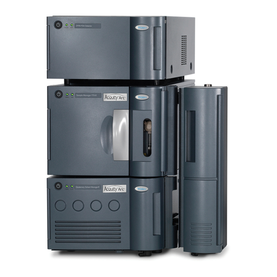
You can also optimize reversed-phase separations that are sensitive to pH and organic-solvent composition. 1.1.5 System components The following illustration depicts an ACQUITY Arc system stack that includes four core modules. Figure 1–1: Instrument modules: Detector Column module Quaternary Solvent Manager-R (QSM-R) - Page 16 • Column module (30-cm Column Heater, 30-cm Column Heater/Cooler, or 30-cm Column Heater-Active) • Detectors (ultra violet/visible, photodiode array, evaporative light scattering, fluorescence, refractive index, or mass spectrometer) 1.1.5.1 Quaternary solvent manager-R The quaternary solvent manager-R (QSM-R) is a low-pressure mixing, high-pressure pump.
- Page 17 Note: Although the same model number is utilized, each of these HPLC optical detectors have specific part numbers to be ordered with the ACQUITY Arc System. Specific chassis alterations and leak management features have been made specifically to utilize these detectors on the ACQUITY Arc System. When ordering, ensure that the detector is specific to, and compatible with, your LC system.
- Page 18 • RADAR, where the instrument concurrently performs scanning and SIR acquisitions. 1.1.5.6 Column technology The ACQUITY Arc system can accommodate any HPLC or UHPLC column in which the particle size is 2.5 µm or greater. It is particularly well-suited to column sizes of 3.0 mm ID or greater.
- Page 19 • 2998 Photodiode Array Detector Overview and Maintenance Guide • 2489 UV Visible Detector Overview and Maintenance Guide • 2414 Refractive Index Detector Overview and Maintenance Guide • 2475 Multi Fluorescence Detector Overview and Maintenance Guide • 2424 Evaporative Light Scattering Detector Overview and Maintenance Guide •...
-
Page 20: Performance Optimization
2.1 General guidelines The ACQUITY Arc system provides the ability to replicate established HPLC methods by emulating a system's dwell volume and mixing behavior. In the instrument method editor, you can select between Path 1 (HPLC emulation path) and Path 2 (UHPLC path). -
Page 21: Carryover
You can measure carryover by observing analyte peaks that appear when you run a blank sample immediately after an analytical sample. Waters specifies carryover on the ACQUITY Arc system at less than 0.002% A common cause of carryover is inadequate washing of the system. -
Page 22: Preventing Leaks
2.5.1 Installation recommendations for fittings Two types of fittings are used within the ACQUITY Arc system: PEEK (polymer- based) fittings and tubing and SST (stainless steel) tubing and fittings. When connecting tubing, heed the following recommendations for installing and tightening fittings. - Page 23 • To prevent band spreading, ensure that the tubing is fully bottomed in the fitting before tightening the compression screw. • For easier accessibility, use long compression screws to attach tubes to the injector and vent valve. • Perform the solvent manager leak test whenever you replace or loosen fittings during maintenance (see the console online Help).
- Page 24 2.5.1.2 Short 1/4-28 fitting with flangeless ferrule and stainless steel lock ring installed on 1/16-inch OD tubing First use or re-installed Compression screw Lock ring Ferrule End of lock ring with larger inside diameter (ID) Tighten the fitting finger-tight. 2.5.1.3 5/16-24 fitting with filter and stainless steel lock ring First use or re-installed Compression screw Lock ring...
- Page 25 2.5.1.4 Stainless steel (gold-plated) fitting with long flats and 2-piece stainless-steel ferrule First use Long flats Compression screw 2-piece stainless-steel ferrule Tighten the fitting finger-tight plus an additional 3/4-turn using a 1/4-inch open-end wrench. Tip: To prevent bandspreading, ensure the tubing is fully bottomed in the fitting before tightening the compression screw.
- Page 26 Tighten the fitting finger-tight plus as much as an additional 1/6-turn using a 1/4- inch open-end wrench. Tip: To prevent bandspreading, ensure the tubing is fully bottomed in the fitting before tightening the compression screw. 2.5.1.5 Stainless steel (gold-plated) fitting with short flats and 2-piece stainless-steel ferrule First use Short flats...
- Page 27 Re-installed Short flats Compression screw 2-piece stainless steel ferrule Tighten the fitting finger-tight plus as much as an additional1/6-turn using a 1/4- inch open-end wrench. Tip: To prevent bandspreading, ensure that the tubing is fully bottomed in the fitting before tightening the compression screw. 2.5.1.6 PEEK fitting with PEEK ferrule and stainless steel lock ring First use or re-installed Compression screw...
- Page 28 2.5.1.7 One-piece PEEK fitting First use or re-installed Tighten the fitting finger-tight. 2.5.1.8 Dual-threaded fitting with locking cap nut First use or re-installed Locking cap nut Gold-plated locking compression screw Back-locking PEEK ferrule To tighten the fitting: Loosen the cap nut from the gold compression screw. Slide the gold compression screw together with the captive ferrule into the inlet of the column (or in-line filter).
- Page 29 2.5.1.9 Dual-threaded, finger-tight fitting with knurled compression screw and captive ferrule First use or re-installed Locking cap nut Knurled locking compression screw Back-locking PEEK ferrule To tighten this fitting for first use: Loosen the cap nut from the dual-threaded, finger-tight fitting. Slide the dual-threaded fitting with captive ferrule into the column inlet.
-
Page 30: Developing Methods
2.5.1.10 High-pressure pin plug First use or re-installed Tighten the pin plug finger-tight, plus up to 1/6-turn using a wrench. 2.6 Developing methods See also: For information about method development and validation, consult the Auto•Blend Plus Technology for Ion Exchange, Size Exclusion, and Reversed-phase Chromatography documentation. -
Page 31: Transferring Methods
2.8 Transferring methods Transferring an LC method from one system to another can sometimes be necessary. For such transfers, the object is to maintain or enhance a separation’s performance by reducing run time, improving resolution, or both. Arc Multi-flow path technology offers plug-and-play method compatibility with HPLC and UHPLC methods. -
Page 32: System Preparation
System preparation Before proceeding, ensure that all of the procedures that explain how to prepare the system modules for operation were performed as specified in the modules' overview and maintenance guides. 3.1 Powering-on the system To power-on the system, you must power-on the system workstation, system modules, and the chromatography software. -
Page 33: Monitoring Module Leds
Open the control panels and console. See: Monitoring from control panels Opening the console Prime the system. See: Priming the system 3.2 Monitoring module LEDs The LEDs on each module LEDs indicate its operational status. Note, however, that the significance of an LED's color differs from one module to another. Note: The 30-cm column heater and column heater/cooler and the 30-cm column heater-active modules are not equipped with LEDs. - Page 34 Alternative: Firmware upload is in progress. Steady red A failure is preventing operation. Cycle power to the sample manager. If the LED remains red, report the problem to Waters Technical Support. Alternative: Firmware upload is complete. 3.2.2.2 Flow LED Flow status is indicated by an LED on the solvent manager’s front panel.
-
Page 35: Monitoring From Control Panels
A failure is preventing the detector from operating. If, after you cycle power to the detector, the LED remains red, report the problem to Waters Technical Service. 3.3 Monitoring from control panels You can monitor the sample manager, solvent manager, column module, and detector from control panels, which you access via the chromatography data system. - Page 36 Figure 3–1: SM FTN-R control panel Run LED – Mirrors the run status LED on the sample manager's front panel, unless communications are interrupted. Current sample heater temperature – Displays the current temperature of the sample heater. Display console icon – When clicked, launches the console software. Sample heater temperature set point –...
-
Page 37: Qsm-R Control Panel
Table 3–4: Additional functions in the SM FTN-R control panel (continued) Control panel function Description Help Displays the console online Help. 3.3.2 QSM-R control panel The control panel of the Quaternary Solvent Manager-R (QSM-R) displays system pressure, total flow rate, and solvent composition. Figure 3–2: QSM-R control panel Flow LED –... -
Page 38: 2489 Uv-Vis Control Panel
Table 3–5: Additional functions in the QSM-R control panel Control panel Description function Start up system Brings the system to operational conditions after an extended idle period or when switching to different solvents. See: Console online Help Prime solvents Displays the Prime Solvents dialog box. Prime seal wash Starts or stops priming the seal wash. -
Page 39: 2998 Pda Control Panel
AU – Displays the absorbance units of wavelength A. If the detector is in dual wavelength mode, the absorbance units of wavelength B also appears. Shutter position – Displays the current position of the detector shutter. Status – Displays the status of the current operation. You can access these additional functions by right-clicking anywhere in the detector control panel. -
Page 40: 2424 Els Control Panel
You can access these additional functions by right-clicking anywhere in the detector control panel. Table 3–7: Additional functions in the 2998 PDA detector control panel Control panel function Description Autozero Resets the detector offsets. Launch Console Launches the console software. Reset module Resets the detector after an error condition. -
Page 41: 2475 Flr Control Panel
Nebulizer temperature set point – Displays the set point for the nebulizer temperature. Nebulizer gas pressure set point – Displays the set point for the nebulizer gas pressure, in kPa, bars, or psi. You specify pressure units in the console software. - Page 42 Figure 3–5: 2475 FLR detector control panel Lamp LED – Mirrors the lamp status LED on the front panel of the detector, unless communications with the detector are lost. Emission units or energy units – Displays the emission units or energy units. Lamp icon –...
-
Page 43: 2414 Ri Control Panel
3.3.7 2414 RI control panel The 2414 Refractive Index detector's control panel displays signal measurement, peak polarity, and the temperatures of the flow cell and external column manager. Run status LED – Mirrors the run status LED on the front panel of the detector, unless communications with the detector are interrupted. -
Page 44: Opening The Console
3.4 Opening the console You can perform the following tasks in the console: • Monitor system performance • Specify settings for certain module parameters • Run diagnostic tests • View an interactive diagram of the module components 3.4.1 Opening the console from Empower software To open the console: From the Empower navigation bar, select Run Samples and then Control Panel. - Page 45 Recommendation: If you are introducing new solvents, prime them at 10 mL/min for 7 minutes. Alternatively, prime the solvents at 10 mL/min for 3 minutes. Ensure that sufficient quantities of solvent are available for priming. Tip: In the console, you can select the Startup System feature to prime all solvents and to specify the solvent composition, flow rate, column and sample temperatures, and needle characterization.
-
Page 46: System Maintenance
Waters Technical Service (800 252-4752). From elsewhere, phone the Waters corporate headquarters in Milford, Massachusetts (USA), or contact your local Waters subsidiary. The Waters Web site includes phone numbers and e-mail addresses for Waters locations worldwide. Visit www.waters.com. When you contact Waters, be prepared to provide this information: •... -
Page 47: Maintenance Procedure And Frequency
Waters Technical Support. To locate system serial numbers: In the console, select a module from the system tree. Click Configure > View module information. Result: The Module Information dialog box displays this information: •... -
Page 48: Spare Parts
The service agent software automatically and securely captures and sends information about the support needs of a system directly to Waters. If you encounter a performance problem when using the console software, manually submit a Connections INSIGHT request to Waters Customer Support. -
Page 49: Configuring Maintenance Warnings
Thus you can minimize unexpected failures and unscheduled downtime during important work. For information explaining how to specify maintenance warnings, consult the Waters console Help. June 12, 2015, 715004747 Rev. A Page 49... -
Page 50: External Connections
See also: For information explaining how to connect chromatographic tubing, see Installation recommendations for fittings Note: A Waters Technical Service representative unpacks and installs the system components. Warning: To avoid spinal or muscular injury, do not attempt to lift the system components without assistance. -
Page 51: External Wiring Connections
5.1.1 External wiring connections Figure 5–1: System rear-panel wiring connections Column module (30-cm CHC shown) Detector SM FTN-R QSM-R June 12, 2015, 715004747 Rev. A Page 51... -
Page 52: Plumbing Connections
5.1.2 Plumbing connections Figure 5–2: System plumbing connections Detector SM FTN-R QSM-R Column module (30-cm CHC shown) June 12, 2015, 715004747 Rev. A Page 52... -
Page 53: Waste-Tubing Connections
5.1.3 Waste-tubing connections Figure 5–3: System waste-tubing connections Solvent tray Detector SM FTN-R QSM-R Column module (30-cm CHC shown) June 12, 2015, 715004747 Rev. A Page 53... -
Page 54: Connecting To The Electricity Source
• Use SVT-type power cord in the United States and HAR-type power cord, or better, in Europe. For requirements elsewhere, contact your local Waters distributor. • Inspect the power cord for damage, and replace it, if necessary. • Power-off and unplug each module before performing any maintenance operation on it. - Page 55 To connections cables: Using the flat-blade screwdriver, attach the positive and negative leads of the signal cable to the connector. Figure 5–4: Positive and negative lead connections June 12, 2015, 715004747 Rev. A Page 55...
- Page 56 Screw Connector Signal cable Insert the connector into the connector port on the instrument's rear panel. Figure 5–5: Inserting connector into connector port Connector port Connector Fit the grounding cable's fork terminal on the rear-panel grounding stud, and secure the terminal using the locking nut. Note: Use the 9/32-inch nut driver to tighten the locking nut until the terminal does not move.
-
Page 57: Ethernet Connections
Figure 5–6: Cable fork terminal on grounding stud Locking nut Fork terminal Grounding stud 5.2 Ethernet connections The sample manager incorporates an internal Ethernet switch that accommodates the PC (workstation) and as many as six system modules. Connect the shielded Ethernet cables from each module to the electronic connections on the rear panel of the sample manager. -
Page 58: A Safety Advisories
Heed all warnings when you install, repair, or operate any Waters instrument or device. Waters accepts no liability in cases of injury or property damage resulting from the failure of individuals to comply with any safety precaution when installing, repairing, or operating any of its instruments or devices. -
Page 59: Specific Warnings
Warning: (Risk of explosion.) A.1.1 Specific warnings A.1.1.1 Burst warning This warning applies to Waters instruments and devices fitted with nonmetallic tubing. Warning: To avoid injury from bursting, nonmetallic tubing, heed these precautions when working in the vicinity of such tubing when it is pressurized: •... -
Page 60: Notices
A.1.1.2 Biohazard warning The following warning applies to Waters instruments and devices that can process material containing biohazards, which are substances that contain biological agents capable of producing harmful effects in humans. Warning: To avoid infection with potentially infectious, human-sourced products, inactivated microorganisms, and other biological materials, assume that all biological fluids that you handle are infectious. -
Page 61: Bottles Prohibited Symbol
Use eye protection when refilling or replacing solvent bottles. Requirement: Wear clean, chemical-resistant, powder-free gloves when handling samples. A.5 Warnings that apply to all Waters instruments and devices When operating this device, follow standard quality-control procedures and the equipment guidelines in this section. Warning: Changes or modifications to this unit not expressly approved by the party responsible for compliance could void the user’s authority to... - Page 62 Advertencia: cualquier cambio o modificación efectuado en esta unidad que no haya sido expresamente aprobado por la parte responsable del cumplimiento puede anular la autorización del usuario para utilizar el equipo. 警告: 未經有關法規認證部門允許對本設備進行的改變或修改,可能會使使用者喪失操作 該設備的權利。 警告: 未经有关法规认证部门明确允许对本设备进行的改变或改装,可能会使使用者丧 失操作该设备的合法性。 경고: 규정 준수를 책임지는 당사자의 명백한 승인 없이 이 장치를 개조 또는 변경할 경우, 이...
- Page 63 Warnung: Bei der Arbeit mit Polymerschläuchen unter Druck ist besondere Vorsicht angebracht: • In der Nähe von unter Druck stehenden Polymerschläuchen stets Schutzbrille tragen. • Alle offenen Flammen in der Nähe löschen. • Keine Schläuche verwenden, die stark geknickt oder überbeansprucht sind.
- Page 64 圧力のかかったポリマーチューブを扱うときは、注意してください。 • 加圧されたポリマーチューブの付近では、必ず保護メガネを着用してください。 • 近くにある火を消してください。 • 著しく変形した、または折れ曲がったチューブは使用しないでください。 • 非金属チューブには、テトラヒドロフラン(THF)や高濃度の硝酸または硫酸などを流さないでくださ い。 • 塩化メチレンやジメチルスルホキシドは、非金属チューブの膨張を引き起こす場合があり、その場 合、チューブは極めて低い圧力で破裂します。 This warning applies to Waters instruments fitted with nonmetallic tubing. This warning applies to instruments operated with flammable solvents. June 12, 2015, 715004747 Rev. A Page 64...
-
Page 65: Warnings That Address The Replacing Of Fuses
Warning: The user shall be made aware that if the equipment is used in a manner not specified by the manufacturer, the protection provided by the equipment may be impaired. Avertissement : L’utilisateur doit être informé que si le matériel est utilisé d’une façon non spécifiée par le fabricant, la protection assurée par le matériel risque d’être défectueuses. - Page 66 Avertissement : pour éviter tout risque d'incendie, remplacez toujours les fusibles par d'autres du type et de la puissance indiqués sur le panneau à proximité du couvercle de la boite à fusible de l'instrument. Warnung: Zum Schutz gegen Feuer die Sicherungen nur mit Sicherungen ersetzen, deren Typ und Nennwert auf den Tafeln neben den Sicherungsabdeckungen des Geräts gedruckt sind.
-
Page 67: Electrical Symbols
Advertencia: Para evitar incendios, sustituir los fusibles por aquellos del tipo y características indicados en la sección "Sustituir fusibles". 警告: 為了避免火災,更換保險絲時,應使用「維護步驟」章節中「更換保險絲」所指 定之相同類型與規格的保險絲。 警告: 为了避免火灾,应更换“维护步骤”一章的“更换保险丝”一节中介绍的相同类 型和规格的保险丝。 경고: 화재의 위험을 막으려면 유지관리 절차 단원의 “퓨즈 교체” 절에 설명된 것과 동 일한 타입 및 정격의 제품으로 퓨즈를 교체하십시오. 警告: 火災予防のために、ヒューズ交換ではメンテナンス項目の「ヒューズの交換」に記載されているタ... -
Page 68: Handling Symbols
A.8 Handling symbols The following handling symbols and their associated statements can appear on labels affixed to the packaging in which instruments, devices, and component parts are shipped. Symbol Description Keep upright! Keep dry! Fragile! Use no hooks! Upper limit of temperature Lower limit of temperature Temperature limitation June 12, 2015, 715004747 Rev. -
Page 69: B Solvent Considerations
Solvent considerations This information applies to the ACQUITY Arc system modules. Warning: Observe Good Laboratory Practice (GLP) at all times, particularly when working with hazardous materials. Consult the Material Safety Data Sheets regarding the solvents you use. Additionally, consult the safety representative for your organization regarding its protocols for handling such materials. -
Page 70: Water
A or type 3.3 . Use brown-stained glassware, to inhibit microbial growth. Use aluminum foil or Waters caps to cover the reservoirs. B.1.4 Water Use water only from a high-quality water purification system. If the water system does not deliver filtered water, filter the water through a 0.2-μm membrane filter. - Page 71 Table B–1: Properties of common solvents (continued) Solvent Vapor pressure mm Hg Boiling Flash (Torr) point (°C) point (°C) n-butyl alcohol 4.4 at 20 °C 117.5 n-butyl chloride 80.1 at 20 °C 78.44 Chlorobenzene 8.8 at 20 °C 131.69 Chloroform 158.4 at 20 °C 61.15 Cyclohexane...
-
Page 72: Solvent Miscibility
Table B–1: Properties of common solvents (continued) Solvent Vapor pressure mm Hg Boiling Flash (Torr) point (°C) point (°C) Tetrahydrofuran 142 at 20 °C 66.0 Toluene 28.5 at 20 °C 110.62 1,2,4-Trichlorobenzene 1 at 20 °C 213.5 Triethylamine 57 at 25 °C 89.5 Trifluoroacetic acid 97.5 at 20 °C... - Page 73 Table B–2: Solvent miscibility (continued) Polarity Solvent Viscosity Boiling Miscibility λ index cP, 20 °C point °C number cutoff (at 1 atm) (at 1 (nm) atm) Ethanol 1.20 78.3 Acetone 0.32 56.3 15, 17 Benzyl alcohol 5.80 205.5 — Methoxyethanol 1.72 124.6 —...
-
Page 74: Solvent Stabilizers
A liquid is classified in the M-number system by testing for miscibility with a sequence of standard solvents. A correction term of 15 units is then either added or subtracted from the cutoff point for miscibility. B.2.2 Solvent stabilizers Certain solvents degrade, or become unstable, over time. Highly unstable solvents represent a potential explosion hazard. - Page 75 Table B–3: UV cutoff wavelengths for common chromatographic solvents (continued) Solvent UV cutoff (nm) Diethyl amine Ethanol Isopropanol Isopropyl ether Methanol n-Propanol Tetrahydrofuran (THF) B.2.4.2 Mixed mobile phases The following table provides approximate wavelength cutoffs for some other solvents, buffers, detergents, and mobile phases. The solvent concentrations represented are those most commonly used.
- Page 76 TRIS HCl, 20 mM, pH 8.0 Triton X-100, 0.1% Waters PIC Reagent A, 1 vial/liter Waters PIC Reagent B-6, 1 vial/liter Waters PIC Reagent B-6, low UV, 1 vial/liter Waters PIC Reagent D-4, 1 vial/liter June 12, 2015, 715004747 Rev. A Page 76...
- Page 77 B.2.4.3 Mobile phase absorbance This section lists the absorbances at several wavelengths for frequently used mobile phases. Choose the mobile phase carefully to reduce baseline noise. The best mobile phase for your application is one that is transparent at the chosen detection wavelengths. With such a mobile phase, ensure that any absorbance is caused only by the sample.
- Page 78 Table B–5: Mobile phase absorbance measured against air or water (continued) Absorbance (AU) at specified wavelength (nm) Triethylamine, 1% 2.33 2.42 2.50 2.45 2.37 1.96 0.50 0.12 0.04 <0.01 Buffers and salts Ammonium acetate, 10 mM 1.88 0.94 0.53 0.29 0.15 0.02 <0.01 —...
- Page 79 Table B–5: Mobile phase absorbance measured against air or water (continued) Absorbance (AU) at specified wavelength (nm) Waters PIC reagents PIC A, 1 vial/L 0.67 0.29 0.13 0.05 0.03 0.02 0.02 0.02 0.02 <0.01 PIC B6, 1 vial/L 2.46 2.50 2.42...
-
Page 80: C Specifications
Specifications C.1 System specifications The following table lists the system feature specifications. Table C–1: System specifications Feature Specification Dwell volume (total Path 1 = 1100 µL system) Path 2 = 700 µL Operating flow rate range 0.001 to 5.000 mL/min, in 0.001 mL increments Maximum operating 9,500 psi pressure... - Page 81 Table C–2: QSM-R specifications (continued) Attribute Specification Gradient formation Low-pressure mixing, quaternary gradient Gradient profiles 11 gradient curves [including linear, step (2), concave (4), and convex (4)] Check valves Passive check valves Flow accuracy +/- 1.0% of set flow at 0.5, 3.0, and 5.0 mL/min [Degassed methanol, gravimetric or volumetric, with a back pressure of ≤6895 kPa (≤69 bar, ≤1000 psig] Flow precision...
-
Page 82: Sample Manager Ftn-R Specifications
Temperature accuracy +/- 0.5 °C at the sensor Temperature stability +/- 1.0 °C at the sensor Injection needle wash Integral, active, and programmable Minimum sample 3 µL residual, using Waters Maximum Recovery 2-mL vials required Sample carryover <0.002% (caffeine) under UV conditions Advanced capabilities Auto-dilution;... -
Page 83: 30-Cm Column Heater And 30-Cm Column Heater And Column Heater/Cooler Specifications
C.4 30-cm Column heater and 30-cm Column heater and column heater/cooler specifications Table C–4: 30-cm CH and 30-cm CHC specifications Attribute Specification Column capacity Single column, up to 7.8 mm I.D.; up to 300 mm length, with filter or guard column; two, 300-mm columns with guards, or three, 300-mm columns with guards Column selection Select as many as three columns using the optional 3-... -
Page 84: 30-Cm Column Heater-Active (Ch-30A) Specifications
C.5 30-cm Column Heater-Active (CH-30A) specifications Table C–5: CH 30-A specifications Attribute Specification Column capacity Single column, up to 4.6 mm I.D.; up to 300 mm length, with column in-line filter or guard column Column compartment 20.0 (or 5.0 °C above ambient) to 90.0 °C, settable in 0.1 temperature range °C increments Column compartment... -
Page 85: Environmental Specifications
Table C–6: Instrument control specifications (continued) Attribute Specification Connections INSIGHT Provides real-time monitoring and automatic notification of instrument performance and diagnostic information C.7 Environmental specifications Table C–7: ACQUITY Arc environmental specifications Attribute Specification Acoustic noise [total system] <65 dBA Operating temperature range 4.0 to 40.0 °C Operating humidity range 20% to 80%, non-condensing... - Page 86 ACQUITY Arc system physical specifications Attribute Specification Width 57.4 cm (22.6 in.) Height 57.1 cm (22.5 in.) Depth 62.8 cm (24.7 in.) Weight 59.1 kg (130.0 lbs) June 12, 2015, 715004747 Rev. A Page 86...
Need help?
Do you have a question about the ACQUITY Arc System and is the answer not in the manual?
Questions and answers