
Subscribe to Our Youtube Channel
Related Manuals for Waters ACQUITY UPLC M-Class


Summary of Contents for Waters ACQUITY UPLC M-Class
- Page 1 ACQUITY UPLC M-Class System Guide 715003588 / Revision A Copyright © Waters Corporation 2014 All rights reserved...
- Page 2 March 10, 2014, 715003588 Rev. A...
-
Page 3: General Information
Corporation assumes no responsibility for any errors that may appear in this document. This document is believed to be complete and accurate at the time of publication. In no event shall Waters Corporation be liable for incidental or consequential damages in connection with, or arising from, its use. For the most recent revision of this document, consult the Waters Web site (waters.com). -
Page 4: Contacting Waters
Contacting Waters ® Contact Waters with enhancement requests or technical questions regarding the use, transportation, removal, or disposal of any Waters product. You can reach us via the Internet, telephone, or conventional mail. Waters contact information: Contacting medium Information Internet The Waters Web site includes contact information for Waters locations worldwide. -
Page 5: Fcc Radiation Emissions Notice
High voltage hazard To avoid electric shock, do not remove the system modules’ Warning: protective panels. The components they cover are not user-serviceable. FCC radiation emissions notice Changes or modifications not expressly approved by the party responsible for compliance, could void the users authority to operate the equipment. This device complies with Part 15 of the FCC Rules. -
Page 6: Operating The Acquity Uplc M-Class System
Audience and purpose This guide is intended for personnel who install, operate, and maintain ACQUITY UPLC M-Class system modules. It gives an overview of the system’s technology and operation. March 10, 2014, 715003588 Rev. A... -
Page 7: Intended Use Of The Acquity Uplc M-Class System
Intended use of the ACQUITY UPLC M-Class system Waters designed the ACQUITY UPLC M-Class system to perform chromatographic separations. The system is for research use only and is not intended for use in diagnostic applications. Calibrating To calibrate LC systems, follow acceptable calibration methods using at least five standards to generate a standard curve. -
Page 8: Ec Authorized Representative
EC authorized representative Waters Corporation Stamford Avenue Altrincham Road Wilmslow SK9 4AX UK Telephone: +44-161-946-2400 Fax: +44-161-946-2480 Contact: Quality manager viii March 10, 2014, 715003588 Rev. A... -
Page 9: Table Of Contents
Safety advisories ....................v Operating the ACQUITY UPLC M-Class system ........... vi Applicable symbols ..................... vi Audience and purpose..................vi Intended use of the ACQUITY UPLC M-Class system ........vii Calibrating ......................vii Quality control ....................vii ISM classification ....................vii ISM Classification: ISM Group 1 Class B ............ - Page 10 Auxiliary solvent manager ................18 μBinary solvent manager .................. 19 μSample manager - fixed loop ................19 Sample organizer ....................19 Trap valve manager................... 20 Detection ......................20 Column technology .................... 21 Software......................22 Options ....................... 22 Additional information ..................23 2 Optimizing Performance ...............
- Page 11 Task-specific hazard warnings................67 Specific warnings ....................69 Caution advisory ....................70 Warnings that apply to all Waters instruments and devices ....71 Warnings that address the replacing of fuses ..........76 Electrical and handling symbols ..............78 Electrical symbols ....................78 Handling symbols ....................
- Page 12 B Specifications ..................81 Features and performance specifications ........... 81 Instrument control .................... 86 Environmental specifications ................. 87 Power requirements ..................87 Physical specifications ..................87 C External Connections ................89 System waste routing ..................89 External wiring connections ................91 Ethernet connections ..................
- Page 13 Properties of common solvents ..............101 Solvent miscibility ................... 103 Using miscibility numbers (M-numbers)............104 Solvent viscosity ....................105 March 10, 2014, 715003588 Rev. A xiii...
- Page 14 March 10, 2014, 715003588 Rev. A...
-
Page 15: Acquity Uplc M-Class System
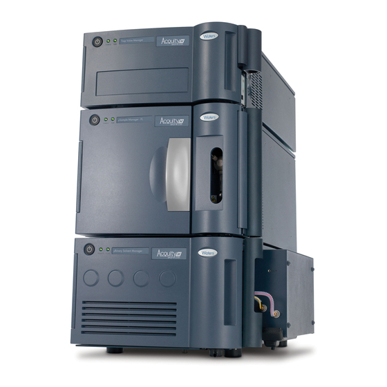
ACQUITY UPLC M-Class system ® Waters designed the ACQUITY UPLC M-Class system to perform a range of chromatographic separations from nano-scale to micro-scale. With a maximum operating pressure of 103,421 kPa (1034 bar, 15,000 psi), an analytical flow rate to 100 μL/min, and a trapping flow rate to 1 mL/min, the system produces optimal linear velocity for columns that range in internal diameter from 75 μm to 1.0 mm. -
Page 16: Configurations Of System Modules
1 ACQUITY UPLC M-Class system Configurations of system modules Shown here are examples of the ACQUITY UPLC M-Class system stack consisting of the core modules. Your system configuration may differ according to the number and types of modules it contains. For example, if your system includes a mass spectrometer, the system modules may be arranged in two separate stacks. - Page 17 Configurations of system modules Examples of typical system configurations for the ACQUITY UPLC M-Class system: Solvent tray Trap valve manager Solvent tray µSample manager -fixed loop Trap valve manager µSample manager µBinary solvent -fixed loop manager Auxiliary solvent µBinary solvent...
-
Page 18: System Components
1 ACQUITY UPLC M-Class system System components The capabilities of the ACQUITY UPLC M-Class system depend on the components configured for operation. The following sections briefly describe the system components and their functions. Optimization • The system components are optimized for use with sub-2-μm, particle liquid chromatography and reduced fluid volumes. -
Page 19: Μbinary Solvent Manager
System components µBinary solvent manager The μbinary solvent manager (μBSM) is a high-pressure pump that provides steady (pulse-free) solvent flow at flow rates ranging from 0.0 to 6.0 μL/min (under closed-loop control) or to 100.0 μL/min (under open-loop control) at 103,421 kPa (1034 bar, 15,000 psi). -
Page 20: Trap Valve Manager
Mass detection The ACQUITY UPLC M-Class system maximizes peak capacity, extending the dynamic range of sample analysis. The ACQUITY UPLC M-Class system can be combined with all types of mass spectrometers, whether analyzing complex samples in wide-ranging matrices with a high resolution MS, or quantifying peptides, metabolites, or other targeted experiments with tandem MS. -
Page 21: Column Technology
System components The ACQUITY UPLC M-Class Driver Pack Release Notes for See also: compatible mass spectrometers and associated MassLynx SCN’s. Column technology Columns may be configured with the TVM using no valves for direct injection, one or two valves for two-dimensional applications. -
Page 22: Software
Options Waters micro cart The optional Waters micro cart provides a mobile platform for the system. It holds the system modules and provides electrical outlets. Used with a mass spectrometer, the cart positions the column outlet close to the mass spectrometer’s inlet probe, minimizing system dead volume. -
Page 23: Additional Information
ACQUITY UPLC M-Class 2D Startup Kit • ACQUITY UPLC M-Class 2D HT Startup Kit Other kits: • ACQUITY UPLC M-Class 75 μm Scale Tubing Kit • ACQUITY UPLC M-Class 300 μm Tubing Kit • ACQUITY UPLC M-Class 1 mm Column Mixer Kit •... - Page 24 1 ACQUITY UPLC M-Class system Visit waters.com for more information and to join the ACQUITY UPLC online community, where you can partake in these activities: • Share information and ask questions of ACQUITY UPLC experts and scientists. • Access ACQUITY UPLC publications and user experiences worldwide.
-
Page 25: Optimizing Performance
Preventing leaks ................29 Sample preparation ................. 30 General guidelines for a microscale system Separations performed on the ACQUITY UPLC M-Class System use smaller ID columns when compared to an analytical UPLC system. Solvent and sample consumption are therefore significantly reduced. - Page 26 Waters column packed with sub-2-micron particles provides sufficient back pressure to retard outgassing. If outgassing occurs. Waters recommends use of the optional solvent stabilization kit. • Do not submerge the waste or degasser vent lines in liquid.
-
Page 27: Dispersion
Dispersion • For best performance, configure eluent compositions with at least 3% A or B. Lesser contributions from either the A or B eluent may result in decreased retention time reproducibility. • Monitor the waste level, to ensure that it is never too high. •... -
Page 28: Contamination
2 Optimizing Performance A common cause of carryover is inadequate washing of the system. Choosing an appropriate wash solvent can minimize carryover for a particular analysis. The wash solvent must be strong enough to dissolve any remaining sample and the wash duration must be long enough to remove the residue from the system. -
Page 29: Preventing Leaks
(See the online Help for the ACQUITY UPLC M-Class system, for information about the set-pressure diagnostic test.) To install capillary tubing: Connect the end nearest the pump source (active end). -
Page 30: Sample Preparation
2 Optimizing Performance After connecting both ends of the tubing, whenever the downstream portion of the new tubing is subject to blocking by means of a valve of other device, perform the set pressure diagnostic test (see the online Help for details), to determine whether leaks are present. Sample preparation Micro-scale UPLC analysis places some additional restrictions on sample preparation. -
Page 31: Preparing The System
Preparing the system Preparing the System Preparing the system for use involves starting the system modules, configuring chromatography data-system software, and starting the console software operations. Contents: Topic Page Preparing the system............... 31 Starting the instrument console............35 Instrument control panels ............... 36 Preparing the system Before you can operate the system you must power-on the system hardware, configure system software, and monitor module status. -
Page 32: Configure The System Software
For software change note (SCN) details, see the associated release notes, on the Waters web site, for the appropriate SCN. Install the ACQUITY UPLC M-Class Driver Pack, update your module firmware, and configure your inlet and system modules. You must refer to the ACQUITY UPLC M-Class Driver Pack... -
Page 33: Status Leds
Power-off the module, and then restart it. If the LED is still steady red, contact your Waters service representative. Flashing red and green Used as a visual identification of a module after it is selected via the console. - Page 34 Power-off the module, and then restart it. If the LED is still steady red, contact your Waters service representative. Flashing red and green Used as a visual identification of a module after it is selected via the console.
-
Page 35: Starting The Instrument Console
Power-off the module, and then restart it. If the LED is still steady red, contact your Waters service representative. Flashing red and green Used as a visual identification of a module after it is selected via the console. -
Page 36: Instrument Control Panels
3 Preparing the System interactive diagrams, which show interconnections and provide diagnostic tools for troubleshooting problems. To start the instrument console from MassLynx software: In the MassLynx window, click Inlet Method. In the Inlet Method window, click the ACQUITY Additional Status tab. Click Display console Instrument control panels You can monitor control panels for the ASM, μBSM, μSM-FL, TVM and... - Page 37 Instrument control panels ASM control panel: Flow LED Status Pump pressure Stop flow Flow rate The following table describes the items appearing in the solvent-manager control panels. Solvent manager control panel: Control panel item Description Flow LED Depicts the actual flow LED, on the front panel of the solvent manager unless communications with the solvent manager are interrupted.
-
Page 38: Μsm-Fl Control Panel
3 Preparing the System Solvent manager control panel: (Continued) Control panel item Description The Stop Flow control immediately stops all Stop flow flow from the solvent-manager. Displays the warning indicator icon when the Warning indicator liters pumped has been exceeded. You can access additional functions, shown in the following table, by right-clicking anywhere in the solvent manager’s control panel. - Page 39 Instrument control panels μSM-FL control panel: Run LED Status Warning indicator Sample temperature Sample-temperature Launch console icon setpoint Column-temperature setpoint The following table describes the items appearing in the μSM-FL’s control panel. μSM-FL control panel: Control panel item Description Run LED Depicts the actual run LED on the front panel, unless communications to the μSM-FL are interrupted.
-
Page 40: Tvm Control Panel
3 Preparing the System You can access these additional functions by right-clicking anywhere in the μSM-FL control panel. Additional functions in the μSM-FL control panel: Control panel function Description Prime syringes Displays the Prime dialog box. See “Priming the μSM-FL” in the Sample Manager - Fixed Loop Overview and Maintenance Information. - Page 41 Instrument control panels The following table describes the items appearing in the TVM’s control panel. TVM control panel item: Control panel item Description Run LED Depicts the actual run LED, on the front panel, unless communications to the TVM are interrupted.
- Page 42 3 Preparing the System March 10, 2014, 715003588 Rev. A...
-
Page 43: Maintaining The System
Waters Technical Service (800 252-4752). From elsewhere, phone the Waters corporate headquarters in Milford, Massachusetts (USA), or contact your local Waters subsidiary. The Waters web site includes phone numbers and e-mail addresses for Waters locations worldwide. Visit www.waters.com. -
Page 44: Maintenance Procedure And Frequency
• System workstation model and operating system version For complete information about reporting shipping damages and submitting claims, see the document Waters Licenses, Warranties, and Support Services on the documentation CD. Locating system serial numbers The serial number on the system’s modules facilitates service and support. - Page 45 CD. • For information on how to configure preventive maintenance alerts based on system usage, see page ACQUITY UPLC M-Class system maintenance procedures: Maintenance Frequency procedure Perform leak test As needed. For instructions about evaluating the...
- Page 46 4 Maintaining the system Solvent manager maintenance procedures: Maintenance Frequency procedure Replace the pump As part of the annual scheduled routine interconnect tubing maintenance and thereafter, as needed. The typical failure modes are as follows: • You see a visible leak •...
- Page 47 Maintenance procedure and frequency Solvent manager maintenance procedures: (Continued) Maintenance Frequency procedure Replace the in-line As needed. The typical failure modes are as follows: filter • High back pressure: the in-line filter causes a high-pressure shutdown. In this case, disconnect the in-line filter.
- Page 48 4 Maintaining the system Solvent manager maintenance procedures: (Continued) Maintenance Frequency procedure Replace the plunger As part of the annual scheduled routine and seals maintenance and thereafter, as needed. The typical failure modes are as follows: • Late eluting peaks are exhibited after a dynamic leak test was performed where the leak rate is above the acceptable limit.
-
Page 49: Troubleshooting
Troubleshooting μSM-FL maintenance procedures: (Continued) Maintenance Frequency procedure Replace the sample As part of the annual scheduled routine syringe maintenance and thereafter, as needed. These are the typical failure modes: • The sample syringe leak test fails. • Air bubbles are in the syringe. •... -
Page 50: General Principles
4 Maintaining the system General principles Follow these general principles for troubleshooting the ACQUITY UPLC M-Class system: • Consider the likely causes of the problem. For example, unresponsive modules can mean that power or signal cables are disconnected or improperly connected. A fluid or vacuum leak can indicate defective tubing or valve connections. - Page 51 Troubleshooting The table below summarizes the most common chromatography, method parameters and sample problems defined at a system-level. ACQUITY UPLC M-Class System troubleshooting: Symptom Suspected cause Possible solution Baseline or Solvent contamination Use only fresh, clean background solvents. fluctuations Controlling...
- Page 52 4 Maintaining the system ACQUITY UPLC M-Class System troubleshooting: (Continued) Symptom Suspected cause Possible solution Baseline or Inadequate solvent If the baseline is steady background blending when running a pre-mixed fluctuations solvent then: (continued) • Ensure that A and B pumps are delivering solvent correctly.
- Page 53 Troubleshooting ACQUITY UPLC M-Class System troubleshooting: (Continued) Symptom Suspected cause Possible solution Erratic retention The system is not • Allow all system times stabilized or chemically components (such as equilibrated the column and detector) sufficient time to stabilize and chemically equilibrate.
- Page 54 4 Maintaining the system ACQUITY UPLC M-Class System troubleshooting: (Continued) Symptom Suspected cause Possible solution Erratic retention Ambient temperature Stabilize the operating times (continued) fluctuations environment temperature (for a minimum of 30 minutes). If the problem persists: • Run the column heater temperature at 5 °C...
- Page 55 Troubleshooting ACQUITY UPLC M-Class System troubleshooting: (Continued) Symptom Suspected cause Possible solution Increasing or Incorrect, degraded or • If contaminated, flush decreasing contaminated column the column with 85% retention times organic solvent. (continued) • Otherwise, clean or replace the column as...
- Page 56 4 Maintaining the system ACQUITY UPLC M-Class System troubleshooting: (Continued) Symptom Suspected cause Possible solution Increasing or Inlet lines blocked • Check lines for decreasing blockages, replace retention times tubing if necessary. (continued) • Clean the solvent inlet filter frit; replace the frit if necessary.
- Page 57 Troubleshooting ACQUITY UPLC M-Class System troubleshooting: (Continued) Symptom Suspected cause Possible solution Early eluting peaks Injection volume or • Reduce the injection fail sample concentration is volume. too high • Dilute the sample. Sample diluent too high in Reduce the injection...
- Page 58 4 Maintaining the system ACQUITY UPLC M-Class System troubleshooting: (Continued) Symptom Suspected cause Possible solution No peaks No spray The Universal See also: (continued) NanoFlow Sprayer Installation and Maintenance Guide on the documentation CD. Incorrect vial position Ensure vial is in correct position.
- Page 59 Troubleshooting ACQUITY UPLC M-Class System troubleshooting: (Continued) Symptom Suspected cause Possible solution Fronting peaks Column or pre-column is Clean the column or (continued) contaminated pre-column or replace. The appropriate See also: column care and use guide on the documentation CD.
- Page 60 4 Maintaining the system ACQUITY UPLC M-Class System troubleshooting: (Continued) Symptom Suspected cause Possible solution Missing peaks Insufficient trapping • Check the inlet method (continued) parameters. • Establish if the trapping column is trapping peptides efficiently. Insufficient initial sample Refer to the laboratory...
- Page 61 Troubleshooting ACQUITY UPLC M-Class System troubleshooting: (Continued) Symptom Suspected cause Possible solution Split or double Injection volume or • Reduce the injection peaks sample concentration is volume. too high disrupting • Dilute the sample. column equilibration Sample diluent is too high...
- Page 62 4 Maintaining the system ACQUITY UPLC M-Class System troubleshooting: (Continued) Symptom Suspected cause Possible solution Tailing peaks with Fitting or interconnection Ensure proper sprayer or a normal retention problem emitter plumbing. time The Universal See also: NanoFlow Sprayer Installation and Maintenance Guide on the documentation CD.
- Page 63 Troubleshooting ACQUITY UPLC M-Class System troubleshooting: (Continued) Symptom Suspected cause Possible solution Loss of sensitivity The programmed flow rate Program the correct flow (continued) is too low rate ensuring it is appropriate for the column I.D. Incorrect mobile phase Make fresh mobile phase...
- Page 64 4 Maintaining the system ACQUITY UPLC M-Class System troubleshooting: (Continued) Symptom Suspected cause Possible solution Loss of sensitivity μSM-FL temperature is Adjust the μSM-FL (continued) too high or low sample compartment temperature. Sample syringe draw From the Method Editor, speed set too high,...
-
Page 65: Troubleshooting With Connections Insight
Connections INSIGHT is an “intelligent” device management (IDM) Web service that enables Waters to provide proactive service and support for the system. To use Connections INSIGHT, you must install its service agent software on a MassLynx workstation. In a client/server system, you must also install the service agent on the computer that controls the system. -
Page 66: Configuring Maintenance Warnings
Waters Quality Parts . Visit www.waters.com/wqp for information about Waters Quality Parts, including how to order them. For information about compatible plates, vials, caps and sample covers, consult the Waters Vials, Filters, and Plates selector at www.waters.com/app/selector/en/index.html. -
Page 67: A Safety Advisories
Task-specific hazard warnings The following symbols warn of risks that can arise when you operate or maintain a Waters instrument or device, or a component of an instrument or device. When one of these symbols appear in a manual’s narrative sections or... - Page 68 Safety Advisories procedures, an accompanying statement identifies the applicable risk and explains how to avoid it. (General risk of danger. When this symbol appears on an Warning: instrument, consult the instrument’s user documentation for important safety-related information before you use the instrument.) (Risk of burn injury from contacting hot surfaces.) Warning: (Risk of electric shock.)
-
Page 69: Specific Warnings
Biohazard warning The following warning applies to Waters instruments and devices that can process material containing biohazards, which are substances that contain biological agents capable of producing harmful effects in humans. -
Page 70: Caution Advisory
Safety Advisories Biohazard and chemical hazard warning This warning applies to Waters instruments and devices that can process biohazards, corrosive materials, or toxic materials. To avoid personal contamination with biohazards, Warning: toxic materials, or corrosive materials, you must understand the hazards associated with their handling. -
Page 71: Warnings That Apply To All Waters Instruments And Devices
Warnings that apply to all Waters instruments and devices Warnings that apply to all Waters instruments and devices When operating this device, follow standard quality-control procedures and the equipment guidelines in this section. Changes or modifications to this unit not expressly approved by the Attention: party responsible for compliance could void the user’s authority to operate the... - Page 72 Safety Advisories Use caution when working with any polymer tubing under pressure: Warning: • Always wear eye protection when near pressurized polymer tubing. • Extinguish all nearby flames. • Do not use tubing that has been severely stressed or kinked. •...
- Page 73 Warnings that apply to all Waters instruments and devices fare attenzione quando si utilizzano tubi in materiale polimerico Attenzione: sotto pressione: • Indossare sempre occhiali da lavoro protettivi nei pressi di tubi di polimero pressurizzati. • Spegnere tutte le fiamme vive nell'ambiente circostante.
- Page 74 Safety Advisories 警告:当有压力的情况下使用管线时,小心注意以下几点: • 当接近有压力的聚合物管线时一定要戴防护眼镜。 • 熄灭附近所有的火焰。 • 不要使用已经被压瘪或严重弯曲的管线。 • 不要在非金属管线中使用四氢呋喃或浓硝酸或浓硫酸。 • 要了解使用二氯甲烷及二甲基亚枫会导致非金属管线膨胀,大大降低管线的耐压能力。 경고: 가압 폴리머 튜브로 작업할 경우에는 주의하십시오. • 가압 폴리머 튜브 근처에서는 항상 보호 안경을 착용하십시오. • 근처의 화기를 모두 끄십시오. • 심하게 변형되거나 꼬인 튜브는 사용하지 마십시오. •...
- Page 75 Warnings that apply to all Waters instruments and devices The user shall be made aware that if the equipment is used in a Warning: manner not specified by the manufacturer, the protection provided by the equipment may be impaired. L’utilisateur doit être informé que si le matériel est utilisé d’une Attention: façon non spécifiée par le fabricant, la protection assurée par le matériel risque...
-
Page 76: Warnings That Address The Replacing Of Fuses
Safety Advisories Warnings that address the replacing of fuses The following warnings pertain to instruments equipped with user-replaceable fuses. If the fuse types and ratings appear on the instrument: To protect against fire, replace fuses with those of the type Warning: and rating printed on panels adjacent to instrument fuse covers. - Page 77 Warnings that address the replacing of fuses If the fuse types and ratings do not appear on the instrument: To protect against fire, replace fuses with those of the type Warning: and rating indicated in the “Replacing fuses” section of the Maintenance Procedures chapter.
-
Page 78: Electrical And Handling Symbols
Safety Advisories Electrical and handling symbols Electrical symbols The following electrical symbols and their associated statements can appear in instrument manuals and on an instrument’s front or rear panels. Electrical power on Electrical power off Standby Direct current Alternating current Protective conductor terminal Frame, or chassis, terminal Fuse... -
Page 79: Handling Symbols
Electrical and handling symbols Handling symbols The following handling symbols and their associated statements can appear on labels affixed to the packaging in which instruments, devices, and component parts are shipped. Keep upright! Keep dry! Fragile! Use no hooks! March 10, 2014, 715003588 Rev. A... - Page 80 Safety Advisories March 10, 2014, 715003588 Rev. A...
-
Page 81: Features And Performance Specifications
Specifications The specifications presented in this document depend on the conditions that exist in individual laboratories. Refer to the site preparation guide, ® or contact Waters Technical Service for more information about specifications. Contents: Topic Page Features and performance specifications ........81 Instrument control ................ - Page 82 B Specifications System specifications: (Continued) Feature Specification System synchronization Injection synchronization between pumps and the sample manager enhances retention time reproducibility Maximum operating pressure 103,421 kPa (1034 bar, 15,000 psi) pH range 2 to 10 Total system delay volume <1 uL Unattended operation Full 96-hour diagnostic data display through console software...
- Page 83 Features and performance specifications µBSM performance specifications: Feature Specification Number of solvents Up to four, in combination of two: A1 or A2, and B1 or B2 Solvent conditioning Integrated vacuum degassing, six lines, with two allocated for the injector needle wash/purge solvents Gradient formation High pressure mixing, binary gradient Pump compositional precision...
- Page 84 B Specifications µSM-FL performance specifications: Feature Specification Injection volume range 0.1 μL to 100.0 μL in 0.1-μL increments; 5-μL loop standard with 1, 2, 5, 10, 20, 50 and 100- μL optional loops; unlimited injection volume during trapping Injection linearity >0.999 (default needle) from 20% to 80% volume for the 5-μL loop Injection modes...
- Page 85 Features and performance specifications µSM-FL performance specifications: (Continued) Feature Specification Minimum sample required 3 μL residual, using Waters’ total recovery 2-mL vials (zero offset) Advanced sample manager Load Ahead and Loop Offline mode, capabilities valve cycling timed event, multi-load with trapping independent of sample...
-
Page 86: Instrument Control
Primary wetted materials DLC, PEEK blend and 316 stainless steel Instrument control The following table lists the instrument control specifications for the ACQUITY UPLC M-Class system. Instrument control specifications: Feature Specification External communications Ethernet interfacing via RJ45 connection to host PC... -
Page 87: Environmental Specifications
Power requirements The following table lists the electrical specifications for the ACQUITY UPLC M-Class system. The total ACQUITY UPLC M-Class system power is a function of the Note: modules and instruments that comprise it. Refer to the module or instrument operator’s guide for further information. - Page 88 B Specifications Notes: • Provide clearance of at least 15.2 cm (6 inches) on the back-side of each component for ventilation. • Provide clearance of at least 7.6 cm (3 inches) at the right-side of the μSM-FL for ventilation. System components physical specifications: System Depth Height...
-
Page 89: System Waste Routing
System waste routing External Connections A Waters Technical Service representative unpacks and installs the ACQUITY UPLC M-Class system modules. Requirements: • Contact Waters Technical Service before moving the system modules. • If you must transport a system component, or remove it from service, contact Waters Technical Service for recommended cleaning, flushing, and packaging procedures. - Page 90 C External Connections This section shows the process waste for a system stack on a micro cart. Example of process waste management: Solvent tray µSM-FL µBSM Process waste container Micro cart March 10, 2014, 715003588 Rev. A...
-
Page 91: External Wiring Connections
External wiring connections External wiring connections Example of electrical and data wiring: Ethernet connectors Ethernet switch µSM-FL Power connectors µBSM Ethernet connections The μSM-FL incorporates an internal, 10/100/1000 megabit, Ethernet switch that accommodates the PC (workstation) and as many as six system modules. Connect the shielded Ethernet cables from each module to the electronic connections on the rear panel of the μSM-FL. -
Page 92: Signal Connections
C External Connections Signal connections Connecting signal cables Refer to the signal connection location shown on the silk-screened label affixed to the rear panel of each system module. Required materials • 9/32-inch nut driver • Flat-blade screwdriver • Connector • Signal cable To connect signal cables: Insert the connector into the connector port on the back of the system... - Page 93 Signal connections Using the flat-blade screwdriver, attach the positive and negative leads of the signal cable to the connector. Screw Connector Signal cable Fit the grounding cable’s fork terminal on the rear panel grounding stud, and secure the terminal with the locking nut. Use the 9/32-inch nut driver to tighten the locking nut until the fork Tip: terminal does not move.
-
Page 94: Connecting To The Electricity Source
Warning: • Use power cord SVT-type in the United States and HAR-type or better in Europe. For other countries’ requirements, contact your local Waters distributor. • Power-off and unplug each system module before performing any maintenance operation on the module. - Page 95 Connecting to the electricity source Micro cart power connections: To circuit A AC line Ethernet switch Detector µSM-FL Micro cart μBSM power strips μBSM To circuit B AC line March 10, 2014, 715003588 Rev. A...
- Page 96 C External Connections March 10, 2014, 715003588 Rev. A...
- Page 97 Solvent Considerations This information applies to the ACQUITY UPLC M-Class System modules. To avoid injury, familiarize yourself with materials Warning: and their hazards, observe Good Laboratory Practice, and consult your organization’s safety representative regarding proper use and handling. See the Material Safety Data Sheets for the solvents you use.
- Page 98 Store mobile phases in borosilicate glass reservoirs type 1, class A or type . Use brown-stained glassware to inhibit microbial growth. Use aluminum foil or Waters caps to cover the reservoirs. Water Use water only from a high-quality water purification system. If the water system does not deliver filtered water, filter the water through a 0.2-μm...
- Page 99 Tip: exceed 100 mM. Solvent recommendations This section lists solvents recommended for the ACQUITY UPLC M-Class System. Contact Waters Customer Service to determine whether you can use solvents that do not appear in the list without adversely affecting performance of system modules or the system itself.
- Page 100 • Contact Waters for recommended system cleaning and flushing procedures. • Contact your Waters sales representative or local technical support organization to determine the typical chromatography conditions or operating parameters suitable for ACQUITY UPLC M-Class system modules. • Chloroform, methylene chloride, halogenated solvents, and toluene can be used in weak dilutions (less than 10% vol.) as additives, modifiers, or...
- Page 101 Properties of common solvents To prevent injury, always remove the solvent bottles Warning: when moving the micro cart or instrument modules or when adding or changing reagents. Solvent manager recommendations • The seal wash system must never run dry, particularly during separations that use a polar mobile phase.
- Page 102 D Solvent Considerations Properties of common solvents: (Continued) Vapor Pressure Boiling Flash Solvent mm Hg (Torr) Point (°C) Point (°C) Chloroform 158.4 at 20 °C 61.15 none Cyclohexane 77.5 at 20 °C 80.72 Cyclopentane 400 at 20 °C 49.26 o-Dichlorobenzene 1.2 at 20 °C 180.48 Dichloromethane...
- Page 103 Solvent miscibility Properties of common solvents: (Continued) Vapor Pressure Boiling Flash Solvent mm Hg (Torr) Point (°C) Point (°C) Triethylamine 57 at 25 °C 89.5 Trifluoroacetic acid 97.5 at 20 °C 71.8 Water 17.54 at 20 °C 100.0 o-xylene 6 at 20 °C 144.41 Solvent miscibility Before you change solvents, refer to the table below to determine solvent...
- Page 104 D Solvent Considerations Solvent miscibility: (Continued) Viscosity Boiling Miscibility λ Cutoff Polarity Solvent cP, 20 °C point °C number index (nm) (@1 atm) (@1 atm) Methoxyethanol 1.72 124.6 –– Acetonitrile 0.37 81.6 11, 17 Acetic acid 1.26 117.9 –– Dimethylformamide 0.90 153.0 ––...
- Page 105 Solvent viscosity A liquid is classified in the M-number system by testing for miscibility with a sequence of standard solvents. A correction term of 15 units is then either added or subtracted from the cutoff point for miscibility. Solvent viscosity Generally, viscosity is not a consideration when you operate with a single solvent or under low pressure.
- Page 106 D Solvent Considerations March 10, 2014, 715003588 Rev. A...
Need help?
Do you have a question about the ACQUITY UPLC M-Class and is the answer not in the manual?
Questions and answers