
Related Manuals for Waters ACQUITY UPLC I-Class


Summary of Contents for Waters ACQUITY UPLC I-Class
- Page 1 ACQUITY UPLC I-Class System Guide 715003736 / Revision B Copyright © Waters Corporation 2014 All rights reserved...
-
Page 2: Copyright Notice
Corporation assumes no responsibility for any errors that may appear in this document. This document is believed to be complete and accurate at the time of publication. In no event shall Waters Corporation be liable for incidental or consequential damages in connection with, or arising from, its use. For the most recent revision of this document, consult the Waters Web site (waters.com). -
Page 3: Customer Comments
Contacting Waters ® Contact Waters with enhancement requests or technical questions regarding the use, transportation, removal, or disposal of any Waters product. You can reach us via the Internet, telephone, or conventional mail. Waters contact information: Contacting medium Information... -
Page 4: Safety Considerations
Safety considerations Some reagents and samples used with Waters instruments and devices can pose chemical, biological, or radiological hazards (or any combination thereof). You must know the potentially hazardous effects of all substances you work with. Always follow Good Laboratory Practice, and consult your organization’s safety representative for guidance. -
Page 5: Applicable Symbols
Consult instructions for use Audience and purpose This guide is intended for personnel who install, operate, and maintain ACQUITY UPLC I-Class system modules. It gives an overview of the system’s technology and operation. Intended use of the ACQUITY UPLC I-Class system Waters designed the ACQUITY UPLC I-Class system to perform chromatographic separations. -
Page 6: Quality-Control
When calibrating mass spectrometers, consult the calibration section of the operator’s guide for the instrument you are calibrating. In cases where an overview and maintenance guide, not an operator’s guide, accompanies the instrument, consult the instrument’s online Help system for calibration instructions. -
Page 7: Ec Authorized Representative
EC authorized representative Waters Corporation Stamford Avenue Altrincham Road Wilmslow SK9 4AX United Kingdom Telephone: +44-161-946-2400 Fax: +44-161-946-2480 Contact: Quality manager... - Page 8 viii...
-
Page 9: Table Of Contents
Safety advisories ....................iv Operating the ACQUITY UPLC I-Class system ..........iv Applicable symbols ....................v Audience and purpose..................v Intended use of the ACQUITY UPLC I-Class system ........v Calibrating ......................v Quality-control ....................vi ISM classification ....................vi ISM Classification: ISM Group 1 Class B ............ - Page 10 Sample manager-FL ..................1-7 Column heater ....................1-8 30-cm Column heater (optional)..............1-8 Column manager (optional)................1-9 Sample organizer (optional) ................1-9 Column technology ..................1-9 Detectors......................1-10 Local Console Controller (optional)............... 1-11 For additional information ................1-11 2 Optimizing Performance ..............2-1 General guidelines ....................
- Page 11 Handling symbols ..................A-12 B External Connections ................B-1 System tubing connections ................B-1 External wiring connections ................. B-4 ACQUITY UPLC I-Class instrument external wiring connections ....B-4 Ethernet connections ..................B-5 Column heater connection................B-5 Signal connections ................... B-5 Making signal connections ................
- Page 12 Table of Contents...
-
Page 13: Acquity Uplc I-Class System
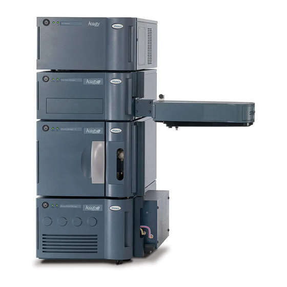
Waters designed the ACQUITY UPLC I-Class system for optimum performance when running difficult assays. Configure it with a mass spectrometer to take full advantage of the system’s design enhancements. Contents: Topic Page UltraPerformance Liquid Chromatography Features of the ACQUITY UPLC I-Class system System modules... -
Page 14: Ultraperformance Liquid Chromatography
UltraPerformance Liquid Chromatography In 2004, Waters made significant advances in instrumentation and column ® design when it introduced UPLC technology to the field of separation science. By employing this technology, Waters’ ACQUITY UPLC systems achieve a marked increase in resolution, speed, and sensitivity in liquid chromatography, when compared to conventional systems. -
Page 15: Features Of The Acquity Uplc I-Class System
Waters has defined this new level of performance as UltraPerformance liquid chromatography. Comparison of chromatographic separations using 5.0-μm and 1.7-μm particles: Each separation was performed on a 2.1 × 50 mm column. Chromatographic conditions for the separations were identical, except for the flow rate, which was scaled according to particle size. -
Page 16: Binary Solvent Manager
Binary solvent manager The ACQUITY UPLC I-Class system employs a binary solvent manager that, like the system, is optimized for sub-2-μm particle liquid chromatography and uses reduced fluid volumes. New pressure management capabilities extend the flow rate envelope for the system to support ballistic gradients. -
Page 17: Detectors
You also benefit from improvements in sensitivity and flexibility. Waters.com for information on compatible Waters mass See also: spectrometers. Features of the ACQUITY UPLC I-Class system... -
Page 18: System Modules
Binary solvent manager The ACQUITY UPLC I-Class core system includes a binary solvent manager, a sample manager (flow-through-needle or fixed loop), a column heater (CH-A), detectors (tunable ultraviolet, photodiode array, eλ photodiode array, or mass spectrometry), and an ACQUITY UPLC column. -
Page 19: Binary Solvent Manager
Maintenance Information for more details. Sample manager-FTN The ACQUITY UPLC I-Class Sample Manager - FTN uses a flow-through-needle mechanism that differs from a loop-based injector. The mechanism aspirates a sample from plates and vials and holds it in the sample needle in preparation for injecting the sample onto the column. -
Page 20: Column Heater
300 mm, or less, length. For columns that exceed 4.6 mm ID, use the ACQUITY UPLC 30-cm column heater/cooler with the appropriate compatibility kit. The ACQUITY UPLC 30-cm column heater/cooler is compatible with Note: I-Class systems. See ACQUITY UPLC Column Compartments Operator’s Overview and Maintenance Information for details. ACQUITY UPLC I-Class System... -
Page 21: Column Manager (Optional)
Column manager (optional) The ACQUITY UPLC I-Class column manager (CM-A) is an option for helping to ensure precise, reproducible separations. The column manager can regulate the temperature of columns from 4 °C to 90 °C. Its troughs can accommodate columns of up to 4.6-mm I.D. and up to 150-mm length, depending on the configuration. -
Page 22: Detectors
UPLC system chromatography produce very narrow ® peaks. The ACQUITY TUV, PDA, and eλ PDA detectors and mass spectrometers collect data at sufficiently fast rates, to acquire these peaks without affecting the sensitivity or accuracy of the peak measurement. 1-10 ACQUITY UPLC I-Class System... -
Page 23: Local Console Controller (Optional)
Designed to emulate a simple keypad, the LCC’s minimal functionality bars it from operating as a standalone controller. Its installation in a system does not supplant CDS control. Rather, Waters designed the LCC to prepare system modules for operation, define initial conditions, and run ACQUITY UPLC system diagnostic tests. - Page 24 1-12 ACQUITY UPLC I-Class System...
- Page 25 Optimizing Performance Follow the advice and guidelines in this chapter to help ensure optimum performance from your ACQUITY UPLC I-Class system. Contents: Topic Page General guidelines Dispersion Carryover Contamination Reproducibility Cycle time (between injections) Preventing leaks Sample preparation...
-
Page 26: Optimizing Performance
When performing fast UPLC analyses, note that a peak of interest can be less than 0.5 seconds wide. Waters recommends a sampling rate of 25 to 50 points across a peak, which provides good quantitation. Sampling rates faster than 20 points per second yield higher baseline noise, requiring you to adjust filter time constants accordingly. -
Page 27: Dispersion
• Filter buffers with a 0.2-μm filter membrane. • Keep concentrated stock solutions, to use when preparing working solutions. • Do not add fresh buffer to old, which can promote microbial growth. • Make fresh buffer solutions daily. • Do not block the degasser vent line. Trim the tubing, if necessary. •... -
Page 28: Carryover
An ACQUITY UPLC I-Class system typically exhibits a bandspread between 4 and 7 µL, or between 6 and 9 µL, depending on system configuration. An Alliance HPLC system can exhibit a bandspread between 35 µL and 50 µL. -
Page 29: Contamination
(verify that sample preparation tools are cleaned thoroughly, for example). Reproducibility The precision (area reproducibility) is less than 0.5% RSD for injection volumes from 2.0 to 10.0 μL (See ACQUITY UPLC I-Class System Specifications for details). Cycle time (between injections) The short run time of a UPLC separation requires efficient use of the time between analyses. -
Page 30: Sample Preparation
Leaks at high pressure fittings (downstream of the i Valves) can leak solvent but do not introduce air. To prevent leaks, follow Waters’ recommendations for the proper tightening of system fittings. Note specifically that different techniques apply to retightening fittings versus installing them for the first time. -
Page 31: Preparing The System
Preparing the System Contents: Topic Page Preparing system hardware Configuring chromatography data software ACQUITY control panels Starting the ACQUITY UPLC Console 3-13... -
Page 32: Preparing System Hardware
Preparing system hardware Powering-on the system Powering-on the system entails starting the ACQUITY UPLC I-Class system workstation, system modules, and chromatography software. Each device or instrument beeps three times and runs a series of startup tests. See “Status LEDs” on page 3-3 “Power LED”... -
Page 33: Power Led
Power LED The power LED, on the left-hand side of a module’s front panel, indicates the power-on or power-off status of the module. This LED is green when power is applied to the unit and unlit when power is not applied. To provide adequate ventilation, the sample manager fans run Tip: continuously, even when the power switch is in the “off”... -
Page 34: Enabling The Leak Sensors
Indicates a module’s failure that prevents its further operation. Power-off the module, and then power-on. If the LED is still steady red, contact your Waters service representative. Enabling the leak sensors When you power-on the system, the leak sensors default to disabled Rule: status unless previously enabled. -
Page 35: Starting Up The System
Starting up the system Use the Start up system function after the system has been idle a short period of time (as much as 12 hours) and when you plan to use the same solvents that you used during the previous run. You can invoke the “Start up system”... -
Page 36: Acquity Control Panels
ACQUITY control panels You can monitor control panels for the binary solvent manager, sample manager, detector, and column manager from your chromatography data system. When Empower software controls the system, the control panels appear at the bottom of the Run Samples window. When MassLynx software controls the system, the control panels appear on the Additional Status tab of the Inlet Editor window. - Page 37 Binary solvent manager control panel items: (Continued) Control panel item Description Status Displays the status of the current operation. System Pressure Displays system pressure, in kPa, bar, or psi. You can customize pressure units via the ACQUITY UPLC Console. Flow Rate Displays the total flow rate of the binary solvent manager, from 0.000 to 2.000 mL/min under normal operation and 0.000 to 8.000...
-
Page 38: Sample Manager Control Panel
Additional functions in the binary solvent manager control panel: Control panel function Description Wash plungers Initiates the plunger wash sequence, which fills and then slowly empties the primary and accumulator chambers (with the current solvent composition) while performing a high speed/volume seal wash. - Page 39 Sample manager control panel: Run LED Status Current sample Current column heater compartment temperature temperature Sample Display ACQUITY UPLC Column heater set compartment set Console point point The following table describes the items in the sample manager’s control panel. Sample manager control panel items: Control panel item Description Run LED...
-
Page 40: Tuv Detector Control Panel
You can access these additional functions by right-clicking anywhere in the sample manager control panel. Additional functions in the sample manager control panel: Control panel function Description Prime Displays the Prime dialog box. “Priming the SM-FTN” in the Sample Manager - Flow Through Needle Operator’s Overview and Maintenance Information. -
Page 41: Column Manager Control Panel
The following table describes the controls and indicators in the TUV detector’s control panel. TUV detector control panel items: Control panel item Description Lamp On/Off LED Displays the actual lamp on/off LED on the front panel of the detector unless communications with the detector are lost. - Page 42 Column manager control panel: Run LED Current temperature Column currently in use Temperature set point The column manager control panel displays the current column temperature and set point. You can edit the set point when the system is idle by clicking on the underlined value.
-
Page 43: Starting The Acquity Uplc Console
Additional functions in the column manager control panel: Control panel function Description Reset CM Resets the column manager, when present, after an error condition Help Displays the ACQUITY UPLC Console online Help Starting the ACQUITY UPLC Console The ACQUITY UPLC Console software provides a way to configure settings, monitor performance, run diagnostic tests, and maintain the system and its modules. - Page 44 3-14 Preparing the System...
- Page 45 Safety Advisories Waters instruments display hazard symbols designed to alert you to the hidden dangers of operating and maintaining the instruments. Their corresponding user guides also include the hazard symbols, with accompanying text statements describing the hazards and telling you how to avoid them.
-
Page 46: A Safety Advisories
Heed all warnings when you install, repair, and operate Waters instruments. Waters assumes no liability for the failure of those who install, repair, or operate its instruments to comply with any safety precaution. -
Page 47: Specific Warnings
The following warnings can appear in the user manuals of particular instruments and on labels affixed to them or their component parts. Burst warning This warning applies to Waters instruments fitted with nonmetallic tubing. Pressurized nonmetallic, or polymer, tubing can burst. Warning: Observe these precautions when working around such tubing: •... - Page 48 Biohazard warning This warning applies to Waters instruments that can be used to process material that can contain biohazards: substances that contain biological agents capable of producing harmful effects in humans.
-
Page 49: Caution Advisory
Chemical hazard warning This warning applies to Waters instruments that can process corrosive, toxic, flammable, or other types of hazardous material. Waters instruments can be used to analyze or Warning: process potentially hazardous substances. To avoid injury with any of these materials, familiarize yourself with the materials and their hazards, observe Good Laboratory Practice (GLP), and consult your organization’s safety... - Page 50 Attention: Changes or modifications to this unit not expressly approved by the party responsible for compliance could void the user’s authority to operate the equipment. Important: Toute modification sur cette unité n’ayant pas été expressément approuvée par l’autorité responsable de la conformité à la réglementation peut annuler le droit de l’utilisateur à...
- Page 51 • Keine Schläuche verwenden, die stark geknickt oder überbeansprucht sind. • Nichtmetallische Schläuche nicht für Tetrahydrofuran (THF) oder konzentrierte Salpeter- oder Schwefelsäure verwenden. • Durch Methylenchlorid und Dimethylsulfoxid können nichtmetallische Schläuche quellen; dadurch wird der Berstdruck des Schlauches erheblich reduziert. Warnings that apply to all Waters instruments...
- Page 52 Attenzione: fare attenzione quando si utilizzano tubi in materiale polimerico sotto pressione: • Indossare sempre occhiali da lavoro protettivi nei pressi di tubi di polimero pressurizzati. • Spegnere tutte le fiamme vive nell'ambiente circostante. • Non utilizzare tubi eccessivamente logorati o piegati. •...
- Page 53 농축 질산 또는 황산과 함께 사용하지 마십시오. • 염화 메틸렌(Methylene chloride) 및 디메틸술폭시드(Dimethyl sulfoxide)는 비금속 튜브를 부풀려 튜브의 파열 압력을 크게 감소시킬 수 있으므로 유의하십시오. 警告:圧力のかかったポリマーチューブを扱うときは、注意してください。 • 加圧されたポリマーチューブの付近では、必ず保護メガネを着用してください。 • 近くにある火を消してください。 • 著しく変形した、または折れ曲がったチューブは使用しないでください。 • 非金属チューブには、テトラヒドロフラン(THF)や高濃度の硝酸または硫酸などを流 さないでください。 • 塩化メチレンやジメチルスルホキシドは、非金属チューブの膨張を引き起こす場合が あり、その場合、チューブは極めて低い圧力で破裂します。 Warnings that apply to all Waters instruments...
- Page 54 Warning: The user shall be made aware that if the equipment is used in a manner not specified by the manufacturer, the protection provided by the equipment may be impaired. Attention: L’utilisateur doit être informé que si le matériel est utilisé d’une façon non spécifiée par le fabricant, la protection assurée par le matériel risque d’être défectueuses.
-
Page 55: Electrical And Handling Symbols
Electrical and handling symbols Electrical symbols These can appear in instrument user manuals and on the instrument’s front or rear panels. Electrical power on Electrical power off Standby Direct current Alternating current Protective conductor terminal Frame, or chassis, terminal Fuse Recycle symbol: Do not dispose in municipal waste. -
Page 56: Handling Symbols
Handling symbols These handling symbols and their associated text can appear on labels affixed to the outer packaging of Waters instrument and component shipments. Keep upright! Keep dry! Fragile! Use no hooks! A-12 Safety Advisories... -
Page 57: System Tubing Connections
External Connections A Waters Technical Service representative unpacks and installs your ACQUITY UPLC I-Class system modules. Configuring ACQUITY UPLC I-Class System Components See also: (P/N 715003144) Requirements: • Contact Waters Technical Service before moving the ACQUITY UPLC I-Class system modules. - Page 58 Solvent flow for ACQUITY UPLC I-Class system configured with an SM-FTN: SM wash Solvent tray solvent BSM solvents Detector Flow cell Valve Valve Column Column heater or manager Sample Manager - FTN Sample syringe To waste Needle Injector valve Injection...
- Page 59 Solvent flow for ACQUITY UPLC I-Class system configured with an SM-FL: Solvent tray BSM solvents SM wash solvents Detector Flow cell Valve Valve Column Column heater or manager Sample Manager - FL Sample syringe To waste Sample Needle Injector loop...
-
Page 60: External Wiring Connections
External wiring connections ACQUITY UPLC I-Class instrument external wiring connections The rear panel connections for ACQUITY UPLC I-Class system modules are shown below. Drain tube outlet Solvent tray Detector Sample organizer Column heater External power and communications cable (CH-A and... -
Page 61: Ethernet Connections
The sample manager is connected internally to the Ethernet switch. Use a Waters switch box if you are running multiple stacks of modules. Tip: Column heater connection The sample manager powers and communicates with the column heater. - Page 62 Required materials • 9/32-inch nut driver • Flat-blade screwdriver • Connector • Signal cable To make signal connections: Insert the connector into the connector port on the back of the system module. Connector port Connector Using the flat-blade screwdriver, attach the positive and negative leads of the signal cable to the connector.
- Page 63 Fit the grounding cable’s fork terminal on the rear panel grounding stud, and secure the terminal with the locking nut. Use the 9/32-inch nut driver to tighten the locking nut until the fork Tip: terminal does not move. Fork terminal Locking nut Grounding stud Binary solvent manager I/O signal connectors...
- Page 64 0-2V Analog 1 Out 0-2V Analog 2 Out − 0-2V Analog 1 Out − 0-2V Analog 2 Out For electrical specifications, see the ACQUITY UPLC I-Class System Specifications document. Binary solvent manager analog-out/event-in connections Signal connection Description Auxiliary 1 In Reserved for future use.
- Page 65 Binary solvent manager analog-out/event-in connections (Continued) Signal connection Description 0−2V Analog 1 Out Outputs the analog signal to a device such as an integrator or strip-chart recorder. Via the Empower or MassLynx software, you can select one of the following signals as the chart out signal: •...
- Page 66 ACQUITY 2996 PDA detector running under MassLynx software control to start. Sample manager I/O signal connectors: 1 2 3 4 5 6 For electrical specifications, see the ACQUITY UPLC I-Class System Specifications document. B-10 External Connections...
-
Page 67: Connecting To The Electricity Source
Warning: • Use power cord SVT-type in the United States and HAR-type or better in Europe. For other countries’ requirements, contact your local Waters distributor. • Power-off and unplug each system module before performing any maintenance operation on the module. - Page 68 Connect the female end of the power cord to the receptacle on the rear panel of each module. Connect the male end of the power cord to a suitable wall outlet. If your system includes the optional FlexCart, connect the Alternative: female end of the FlexCart's electrical cables (included in the startup kit) to the receptacle on the rear panel of each system module.
Need help?
Do you have a question about the ACQUITY UPLC I-Class and is the answer not in the manual?
Questions and answers