Waters Xevo TQD Operator's, Overview And Maintenance Manual
Hide thumbs
Also See for Xevo TQD:
- Overview and maintenance manual (250 pages) ,
- Knowledge base (2 pages)

Related Manuals for Waters Xevo TQD


Summary of Contents for Waters Xevo TQD
- Page 1 Waters Xevo TQD Operator’s Overview and Maintenance Guide Revision A Copyright © Waters Corporation 2011 All rights reserved...
-
Page 2: Copyright Notice
Corporation assumes no responsibility for any errors that may appear in this document. This document is believed to be complete and accurate at the time of publication. In no event shall Waters Corporation be liable for incidental or consequential damages in connection with, or arising from, its use. -
Page 3: Contacting Waters
Contacting Waters ® Contact Waters with questions regarding any Waters product. You can reach us via the Internet, telephone, or conventional mail. Waters contact information: Contacting medium Information Internet The Waters Web site includes contact information for Waters locations worldwide. -
Page 4: Safety Considerations
Considerations specific to the Xevo TQD Solvent leakage hazard The source exhaust system is designed to be robust and leak-tight. Waters recommends you perform a hazard analysis, assuming a maximum leak into the laboratory atmosphere of 10% LC eluate. - Page 5 Overload hazard To prevent personal injury, ensure equipment placed on top of Warning: the Xevo TQD does not exceed 15kg. Glass-breakage hazard To avoid injuries from broken glass, falling objects, Warning: or exposure to toxic or biohazardous substances, never place...
- Page 6 To avoid burn injuries, ensure the source heater is turned off and the ion block is cool before performing maintenance on these components. Xevo TQD high temperature hazard: Source enclosure assembly TP03406 Hazards associated with removing an instrument from service...
-
Page 7: Safety Advisories
The need to decontaminate other vacuum areas of the instrument depends on the kinds of samples the instrument analyzed and their levels of concentration. Do not dispose of the instrument or return it to Waters for repair until the authority responsible for approving its removal from the premises specifies the extent of decontamination required and the level of residual contamination permissible. -
Page 8: Operating This Instrument
Operating this instrument When operating this instrument, follow standard quality-control (QC) procedures and the guidelines presented in this section. Applicable symbols Symbol Definition Manufacturer Date of manufacture Part number Serial number Supply ratings Authorized representative of the European Community Confirms that a manufactured product complies with all applicable European Community directives Australia C-Tick EMC Compliant... -
Page 9: Audience And Purpose
TRIZAIC™ UPLC options, or optional third-party sources (DART , DESI, or LDTD™), the Xevo TQD does not comply with the European Union In Vitro Diagnostic Device Directive 98/79/EC. Calibrating To calibrate LC systems, follow acceptable calibration methods using at least five standards to generate a standard curve. - Page 10 • Prior to the instrumental analysis, use appropriate sample pretreatment such as protein precipitation, liquid/liquid extraction (LLE), or solid phase extraction (SPE) to remove matrix interferences. • Whenever possible, verify method accuracy and precision using matrix-matched calibrators and QC samples. •...
-
Page 11: Ism Classification
Class A products are suitable for use in commercial (that is, nonresidential) locations and can be directly connected to a low-voltage, power-supply network. EC authorized representative Waters Corporation (Micromass UK Ltd.) Floats Road Wythenshawe Manchester M23 9LZ United Kingdom... -
Page 13: Table Of Contents
EC authorized representative ................xi 1 Specifications and Operating Modes ..........1-1 Uses and compatibility ..................1-2 ACQUITY H-Class and nanoACQUITY Xevo TQD UPLC/MS systems..1-5 Non-ACQUITY devices for use with the Xevo TQD........1-7 Software and data system ................1-7 Instrument Console software ................ - Page 14 NanoFlow source.................... 1-10 Atmospheric solids analysis probe (ASAP)........... 1-10 Atmospheric pressure gas chromatography (APGC) ........1-11 TRIZAIC UPLC source .................. 1-11 IntelliStart Fluidics system ................1-11 Functionality ....................1-11 System operation ................... 1-12 Ion optics ......................1-13 MS operating modes ..................1-14 MS/MS operating modes ................
- Page 15 3 Changing the Mode of Operation ............3-1 ESI mode ......................3-2 Installing the ESI probe .................. 3-2 Removing the ESI probe.................. 3-4 ESCi mode ......................3-5 Optimizing the ESI probe for ESCi operation..........3-5 APCI mode ......................3-5 Installing the IonSABRE II probe ..............3-6 Removing the IonSABRE II probe ..............
- Page 16 Installing and removing the corona pin ............ 4-12 Installing the corona pin in the source ............4-12 Removing the corona pin from the source ............ 4-15 Operating the source isolation valve ............4-16 Removing O-rings and seals ................. 4-19 Cleaning the instrument case ..............4-20 Emptying the exhaust trap bottle ...............
- Page 17 Cleaning the ion guide assembly ..............4-55 Removing the ion block assembly and ion guide from the source assembly 4-55 Cleaning the ion guide assembly ..............4-57 Removing the differential aperture from the ion guide ....... 4-60 Fitting the differential aperture to the ion guide assembly ......4-62 Fitting the ion guide assembly to the source assembly .......
- Page 18 Warning symbols ....................A-2 Task-specific hazard warnings................ A-2 Specific warnings ..................... A-3 Caution symbol ....................A-5 Warnings that apply to all Waters instruments ......... A-5 Electrical and handling symbols ..............A-12 Electrical symbols ..................A-12 Handling symbols ..................A-13 B External Connections ................B-1 External wiring and vacuum connections ..........
- Page 19 Connecting to the nitrogen gas supply ............. B-12 Connecting to the collision cell gas supply ..........B-14 Connecting the nitrogen exhaust line ............B-14 Connecting the liquid waste line ............... B-17 Connecting the workstation ................ B-19 Connecting Ethernet cables ................ B-19 I/O signal connectors ..................
- Page 20 Table of Contents...
- Page 21 Specifications and Operating Modes This chapter describes the instrument, including its controls and connections for gas and plumbing. Contents: Topic Page Uses and compatibility Ionization techniques and source probes IntelliStart Fluidics system 1-11 Ion optics 1-13 MS operating modes 1-14 MS/MS operating modes 1-15 Sample inlet...
-
Page 22: Specifications And Operating Modes
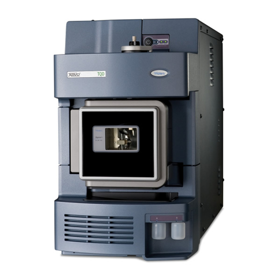
Optional ASAP source. For information on installing and removing the optional APGC, TRIZAIC, and ASAP sources, refer to the operator’s guide supplements supplied with them. You can also use the Xevo TQD with the following optional third-party sources: ® •... - Page 23 Xevo TQD: TP03406 Uses and compatibility...
- Page 24 Xevo TQD with visor up: TP03407 Specifications and Operating Modes...
-
Page 25: Acquity H-Class And Nanoacquity Xevo Tqd Uplc/Ms Systems
If you are not using your instrument as part of an ACQUITY UPLC system, refer to the documentation for your LC system. 1. In Waters product documentation, the term “fluidics” denotes plumbing connections and components and the fluid pathways within and among instruments or devices. It also appears in the product name “IntelliStart™... - Page 26 Xevo TQD with nanoACQUITY UPLC system © Similar to the ACQUITY UPLC system, the nanoACQUITY uses the optional NanoFlow source on the Xevo TQD. It is designed for capillary-to-nano-scale separations. Its sensitivity, resolution, and reproducibility well suit it for Specifications and Operating Modes...
-
Page 27: Non-Acquity Devices For Use With The Xevo Tqd
For further instruction, see the nanoACQUITY UPLC System Operator’s Guide or Controlling Contamination in LC/MS Systems (part number 715001307). You can find these documents on http://www.waters.com; click Services and Support > Support. Non-ACQUITY devices for use with the Xevo TQD... -
Page 28: Instrument Console Software
• Using IntelliStart software to automatically tune and mass calibrate the mass spectrometer. • Running samples. • Monitoring the run. • Acquiring data. • Processing data. • Reviewing data. • Printing data. See MassLynx v4.1 user documentation and online Help for more information on using MassLynx software. -
Page 29: Ionization Techniques And Source Probes
Ionization techniques and source probes Electrospray ionization (ESI) In electrospray ionization (ESI), a strong electrical charge is applied to the eluent as it emerges from a nebulizer. The droplets that compose the resultant aerosol undergo a reduction in size (solvent evaporation). As solvent continues to evaporate, the charge density increases until the droplet surfaces eject ions (ion evaporation). -
Page 30: Nanoflow Source
APCI, or dual mode, which switches rapidly between APPI and APCI ionization modes. NanoFlow source “NanoFlow” is the name given to several techniques that use low flow rate electrospray ionization. The NanoFlow source allows electrospray ionization in the flow rate range 5 to 1000 nL/min. For a given sample concentration, the ion currents observed approximate those seen in normal flow rate electrospray. -
Page 31: Atmospheric Pressure Gas Chromatography (Apgc)
Atmospheric pressure gas chromatography (APGC) The Waters APGC couples an Agilent GC with the Xevo TQD, making it possible to perform LC and GC analyses in the same system, without compromising performance. The APGC provides complementary information to the LCMS instrument, enabling analysis of compounds of low molecular weight and/or low-to-intermediate polarity. -
Page 32: System Operation
IntelliStart Fluidics system: Selector valve Waste Column Xevo Pump Wash TQD probe Reservoir A Reservoir B System operation The software automatically controls solvent and sample delivery during auto-tuning, auto-calibration, and method development. The selector valve systematically makes connections between the fluidics components to carry out the operations processed by the software. -
Page 33: Ion Optics
Ion optics The mass spectrometer’s ion optics operate as follows: Samples from the LC or Intellistart fluidics system are introduced at atmospheric pressure into the ionization source. The ions pass through the sample cone into the vacuum system. The ions pass through the transfer optics (the ion guide) to the first quadrupole, where they are filtered according to their mass-to-charge ratios. -
Page 34: Ms Operating Modes
MS operating modes The following table shows the MS operating modes. MS operating modes: Operating mode Collision cell Pass all masses Resolving (scanning) Resolving (static) Pass all masses In MS mode, the instrument can acquire data at scan speeds as high as 10,000 Da/s. -
Page 35: Ms/Ms Operating Modes
MS/MS operating modes The following table shows the MS/MS operating modes, described in more detail in the following pages. MS/MS operating modes: Operating mode Collision cell Product Static (at Fragment Scanning (daughter) ion precursor mass) precursor ions spectrum and pass all masses Precursor Scanning... -
Page 36: Product (Daughter) Ion Mode
Product (daughter) ion mode Product ion mode is the most commonly used MS/MS operating mode. You can specify an ion of interest for fragmentation in the collision cell, thus yielding structural information. Product ion mode: Collision cell Static (at precursor mass) Fragmenting Scanning precursor ions and... -
Page 37: Precursor (Parent) Ion Mode
Precursor (parent) ion mode Precursor ion mode: Collision cell Scanning Fragmenting Static (at product mass) precursor ions and passing all masses Typical application You typically use the precursor ion mode for structural elucidation—that is, to complement or confirm product scan data—by scanning for all the precursors of a common product ion. - Page 38 RADAR In RADAR mode the Xevo TQD rapidly alternates between MRM and full scan MS acquisition modes. The instrument tracks target analytes with precision in MRM mode, while at the same time scanning (in MS mode) the background for all other components.
-
Page 39: Constant Neutral Loss Mode
Constant neutral loss mode Constant neutral loss mode detects the loss of a specific neutral fragment or functional group from an unspecified precursor(s). The scans of MS1 and MS2 are synchronized. When MS1 transmits a specific precursor ion, MS2 “looks” to see whether that precursor loses a fragment of a certain mass. -
Page 40: Leak Sensors
Leak sensors Leak sensors in the Xevo TQD and the drip trays of the ACQUITY UPLC system continuously monitor system components for leaks. A leak sensor stops system flow when its optical sensor detects about 1.5 mL of accumulated, leaked liquid in its surrounding reservoir. At the same time, the ACQUITY UPLC Console displays an error message alerting you that a leak has developed. -
Page 41: Rear Panel Connections
Rear panel connections The following figure shows the rear panel locations of the connectors used to operate the instrument with external devices. Instrument rear panel: Event inputs and outputs Shielded Ethernet Roughing pump control Power Turbo vacuum Source vacuum Collision cell gas inlet Source vent Nitrogen inlet... - Page 42 1-22 Specifications and Operating Modes...
- Page 43 Preparing for Operation This chapter describes how to start and shut down the instrument. Contents: Topic Page Starting the mass spectrometer Preparing the IntelliStart Fluidics system Rebooting the instrument Leaving the mass spectrometer ready for operation...
-
Page 44: Preparing For Operation
Starting the mass spectrometer The Waters Xevo TQD is compatible with the ACQUITY UPLC system; if you are not using an ACQUITY UPLC system, refer to the documentation relevant to the system you are using (see “Non-ACQUITY devices for use with Xevo TQD”... - Page 45 Power-on the ACQUITY UPLC system workstation, and log in. Press the power switch on the top, right-hand side of the mass spectrometer and the switches on the top, left-hand sides of the ACQUITY instruments. Each system instrument runs a series of startup tests. Result: Allow 3 minutes for the embedded PC to initialize and sound an alert indicating that the PC is ready.
-
Page 46: Verifying The Instrument's State Of Readiness
If clicking Resolve fails to put the instrument into Operate mode, Tip: IntelliStart software displays corrective actions in the Instrument Console. Verifying the instrument’s state of readiness When the instrument is in good operating condition, the power and Operate LEDs show constant green. You can view any error messages in IntelliStart software. -
Page 47: Running The Instrument At Different Flow Rates
Running the instrument at different flow rates The ACQUITY UPLC system runs at high flow rates. To optimize desolvation, and thus sensitivity, run the ACQUITY Xevo TQD system at appropriate gas flows and desolvation temperatures. IntelliStart software automatically sets these parameters when you enter a flow rate, according to the following table. -
Page 48: Preparing The Intellistart Fluidics System
Preparing the IntelliStart Fluidics system For additional information, see page B-17 Appendix D To avoid accidental spillage damage to the instrument, do not Caution: store large-volume solvent reservoirs on top of the instrument. Installing the reservoir bottles Use standard reservoir bottles (15 mL) for instrument setup and calibration. Use the Low-volume Adaptor Kit (sold separately) to infuse smaller volumes. - Page 49 Remove the reservoir bottle caps. Screw the reservoir bottles onto the instrument, as shown below. TP03410 For each reservoir bottle, ensure that the end of the solvent delivery tube is positioned so that it is close to, but does not touch, the bottom of the bottle.
-
Page 50: Purging The Infusion Pump
Purging the infusion pump Whenever you replace a solution bottle, purge the infusion pump with the solution that you are going to use next. See the mass spectrometer’s online Help for details. Ensure that the end of the tubing is fully submerged in the Requirement: solvent in the wash reservoir. -
Page 51: Leaving The Mass Spectrometer Ready For Operation
Remove the PEEK tubing from the reset button aperture. Wait until the reboot sequence ends before starting the MassLynx software. An audible alert sounds when the reboot sequence is complete. Tip: Leaving the mass spectrometer ready for operation Leave the mass spectrometer in Operate mode except in the following cases: •... - Page 52 2-10 Preparing for Operation...
- Page 53 • APCI (atmospheric pressure chemical ionization) • Combined Atmospheric Pressure Photoionization (APPI/APCI) • NanoFlow For details about other Waters and third-party source options, refer to the documentation supplied with the source. Contents: Topic Page ESI mode ESCi mode APCI mode...
-
Page 54: Changing The Mode Of Operation
ESI mode The following sections explain how to install and remove an ESI probe. For further details on running ESI applications, see page 1-9. Installing the ESI probe Required material Chemical-resistant, powder-free gloves To install the ESI probe: The LC system connections, ESI probe, and source can Warning: be contaminated with biohazardous and/or toxic materials. - Page 55 With the probe label facing you, carefully slide the ESI probe into the hole in the probe adjuster assembly, ensuring that the probe location dowel aligns with the location hole of the probe adjuster assembly. Probe label Probe locking ring Probe location dowel Location hole of the probe adjuster assembly...
-
Page 56: Removing The Esi Probe
To avoid electric shock, do not use stainless steel tubing Warning: or stainless steel finger-tight screws to connect the selector valve to the ESI probe; use the PEEK tubing and natural (beige) colored PEEK finger-tight screws supplied with the instrument. Using PEEK tubing equal to 0.004-inch ID, connect port S of the selector valve to the ESI probe. -
Page 57: Esci Mode
The ESI probe tip is sharp. To avoid puncture wounds, Warning: handle the probe with care. Carefully remove the ESI probe from the probe adjuster assembly. If available, fit the protective sleeve to the ESI probe tip. ESCi mode To run ESCi applications, you must fit an ESI probe and corona pin to the ESI/APCI/ESCi source enclosure. -
Page 58: Installing The Ionsabre Ii Probe
APCI mode: IonSABRE II probe Sample cone Corona pin Hot gas from the IonSABRE II probe passes between the sample cone and the corona pin, which is typically operated with a discharge current of 5 µA. Mobile phase molecules rapidly react with ions generated by the corona discharge to produce stable reagent ions. - Page 59 Prepare the instrument for working on the source (see page 4-7). With the probe label facing toward you, carefully slide the IonSABRE II probe into the hole in the probe adjuster assembly, ensuring that the probe location dowel aligns with the probe adjuster assembly location hole.
-
Page 60: Removing The Ionsabre Ii Probe
To avoid electric shock, do not use stainless steel tubing Warning: or stainless steel finger-tight screws to connect the selector valve to the IonSABRE II probe; use the PEEK tubing and natural (beige) colored PEEK finger-tight screws supplied with the instrument. -
Page 61: Combined Appi/Apci Source
Unscrew the probe locking ring. Carefully remove the probe from the probe adjuster assembly. Combined APPI/APCI source Operate this optional, replacement source enclosure in APPI, APCI, or dual APPI/APCI mode. Dual-mode APPI/APCI performs rapid switching between ionization modes. APPI operation In atmospheric pressure photoionization (APPI) mode, the source is fitted with an IonSABRE II probe and the APPI lamp drive assembly is advanced into the source. -
Page 62: Apci Operation
APCI operation The atmospheric pressure chemical ionization (APCI) mode produces singly charged protonated or deprotonated molecules for a large range of nonvolatile analytes. In APCI mode, the source is fitted with an APCI corona pin. Unused, the APPI lamp drive assembly is retracted from the source. APCI mode: IonSABRE II probe Sample cone... -
Page 63: Dual-Mode Operation
Dual-mode operation Dual-mode operation enables rapid switching between APPI and APCI ionization modes and allows high-throughput operations (for example, for sample screening). You replace the standard corona pin with a specially shaped APPI/APCI corona pin, so that the APPI lamp holder can be advanced into the source for dual operation. -
Page 64: The Combined Appi/Apci Source Components
The combined APPI/APCI source components The combined APPI/APCI source comprises the standard IonSABRE II probe and a source enclosure with an APPI lamp drive incorporated. The combined APPI/APCI source enclosure: APPI lamp drive assembly To prevent damage to the corona pin and lamp assembly, Caution: ensure that the lamp assembly does not touch the corona pin when the source enclosure door is closed. -
Page 65: Installing The Combined Appi/Apci Source
APPI lamp drive assembly inside the source enclosure: APPI lamp drive assembly Source enclosure IonSABRE II probe UV lamp and repeller electrode TP03201 Installing the combined APPI/APCI source Required material Chemical-resistant, powder-free gloves To install the combined APPI/APCI source: The source components can be contaminated with Warning: biohazardous and/or toxic materials. - Page 66 The probe and source can be hot. To avoid burn injuries, Warning: take great care while working with these components. Remove the probe from the currently installed source. • If you are removing an ESI probe, see page 3-4. • If you are removing an IonSABRE II probe, see page 3-8.
-
Page 67: Removing The Ionsabre Ii Probe And Appi/Apci Source Enclosure
Removing the IonSABRE II probe and APPI/APCI source enclosure Required material Chemical-resistant, powder-free gloves To remove the combined APPI/APCI source The source components can be contaminated with Warning: biohazardous and/or toxic materials. Always wear chemical-resistant, powder-free gloves while performing this procedure. -
Page 68: Nanoflow Source
NanoFlow source The NanoFlow source enclosure comprises the NanoFlow stage (for x-axis, y-axis, and z-axis adjustment), the sprayer-enclosure, and a microscope camera. NanoFlow source, stage and microscope camera: Microscope camera Sprayer enclosure X, Y, Z stage TP03199 A sprayer is mounted on an X, Y, Z stage (three-axis manipulator) that slides on a pair of guide rails that allow its withdrawal from the source enclosure for maintenance and changes. -
Page 69: Installing The Nanoflow Source
Installing the NanoFlow source Required material Chemical-resistant, powder-free gloves To install the NanoFlow source: The source components can be contaminated with Warning: biohazardous and/or toxic materials. Always wear chemical-resistant, powder-free gloves while performing this procedure. To avoid electric shock, ensure that the instrument is Warning: prepared for working on the source before commencing this procedure. - Page 70 (mounted beneath the stage on the front of the NanoFlow source) and your sprayer. For details regarding how to fit each sprayer, see the corresponding Tip: reference: • Waters Universal NanoFlow Sprayer Installation and Maintenance Guide (part number 71500110107) • “Fitting a borosilicate glass capillary (nanovial)” on page 3-19 •...
-
Page 71: Fitting A Borosilicate Glass Capillary (Nanovial)
The NanoFlow stage contains a high-voltage interlock, so Caution: the capillary voltage (the voltage applied to the sprayer assembly) and the sampling cone voltage remain disabled until the sprayer is pushed fully forward in the source. Connect the high-voltage cable to the instrument’s HV connection. High-voltage cable 10. - Page 72 To fit a borosilicate glass capillary (nanovial): To avoid lacerations, puncture injuries, and Warning: possible contamination with biohazardous and toxic samples, do not touch the sharp end of the capillary. Capillaries are extremely fragile. Take great care when Caution: handling them. Always hold their blunt end, never the sharp end, which can easily be damaged.
- Page 73 Carefully remove the new borosilicate glass capillary from its case by lifting vertically while pressing on the foam with two fingers. Foam Capillary Load sample into the capillary using a fused silica syringe needle or a GELoader tip, minimizing any bubbles between the capillary tip and the sample.
-
Page 74: Positioning The Borosilicate Glass Capillary Tip
Sprayer assembly: PTFE tubing Ferrule Union Knurled nut Blue conductive elastomer Glass capillary 5 mm 12. Screw the sprayer back into the assembly. 13. Replace the sprayer cover. 14. On the MassLynx MS Tune window, ensure that the Capillary parameter on the ES+/- Source tab is set to 0 kV. To ensure that the capillary tip does not collide with the Caution: cone or the side of the source, adjust the sprayer tip position before... -
Page 75: Restarting A Stalled Borosilicate Glass Capillary Electrospray
2 mm. Capillary tip position: Cone aperture diameter For tuning instructions, see the MassLynx Xevo TQD online help topic, “Tuning manually for NanoFlow operation”. Restarting a stalled borosilicate glass capillary electrospray Should the spray stop, you can restart it. To do so, in the Tune window, set Capillary to 0 kV. - Page 76 3-24 Changing the Mode of Operation...
-
Page 77: Maintenance Procedures
Maintenance Procedures This chapter provides the maintenance guidelines and procedures necessary to maintain the instrument’s performance. Keep to a maintenance schedule, and perform maintenance as required and described in this chapter. Contents: Topic Page Maintenance schedule Spare parts Safety and handling Troubleshooting with Connections INSIGHT Preparing the instrument for working on the source Removing and refitting the source enclosure... - Page 78 Contents: Topic Page Cleaning or replacing the corona pin 4-84 Replacing the IonSABRE II probe heater 4-85 Replacing the ion block source heater 4-87 Replacing the source assembly seals 4-92 Replacing the air filter 4-95 Replacing the roughing pump oil 4-97 Replacing the roughing pump’s oil demister element 4-100...
-
Page 79: Maintenance Schedule
Maintenance schedule The following table lists periodic maintenance schedules that ensure optimum instrument performance. The maintenance frequencies shown apply to instruments that normally receive moderate use. Maintenance schedule: Procedure Frequency For information... Clean the instrument case. As required. page 4-20. Empty the exhaust trap bottle Check daily, empty as page... - Page 80 Maintenance schedule: Procedure Frequency For information... Clean the IonSABRE II probe When sensitivity page 4-77. tip. (Options using the decreases to IonSABRE II probe only.) unacceptable levels or when significant chemical interference is present. Replace the IonSABRE II When sensitivity page 4-78.
-
Page 81: Spare Parts
UV lamp bulb. Replace the APPI lamp drive Annually. page 4-108. assembly O-rings. Spare parts Replace only the parts mentioned in this document. For spare parts details, see the Waters Quality Parts Locator on the Waters Web site’s Services/Support page. Spare parts... -
Page 82: Troubleshooting With Connections Insight
Connections INSIGHT is an “intelligent” device management (IDM) Web service that enables Waters to provide proactive service and support for the ACQUITY UPLC system. To use Connections INSIGHT, you must install its service agent software on your MassLynx workstation. In a client/server system, the service agent must also be installed on the computer from which you control the system. -
Page 83: Safety And Handling
Safety and handling Bear in mind the following safety considerations when performing maintenance procedures: The instrument components can be contaminated with Warning: biologically hazardous or toxic materials. Always wear chemical-resistant, powder-free gloves while handling the components. To prevent injury, always observe Good Laboratory Practice Warning: when handling solvents, changing tubing, or operating the instrument. -
Page 84: Removing And Refitting The Source Enclosure
In the Instrument Console, click Stop Flow to stop the LC flow or, if column flow is required, divert the LC flow to waste as follows: In the Instrument Console system tree, expand Xevo TQD, Interactive Fluidics. Click Control Select Waste as the flow state. - Page 85 To remove the source enclosure: The source components can be contaminated with Warning: biohazardous and/or toxic materials. Always wear chemical-resistant, powder-free gloves while performing this procedure. Prepare the instrument for working on the source (see page 4-7). The probe and source can be hot. To avoid burn injuries, Warning: take great care while working with these components.
- Page 86 Using both hands, grasp the source enclosure and lift it vertically off the two supporting studs on the source adaptor housing. Cable storage positions Supporting stud TP03164 Source enclosure Store the cables neatly by plugging them into the cable-storage positions on the rear of the source enclosure.
-
Page 87: Fitting The Source Enclosure To The Instrument
Fitting the source enclosure to the instrument Required material Chemical-resistant, powder-free gloves To fit the source enclosure: The source components can be contaminated with Warning: biohazardous and/or toxic materials. Always wear chemical-resistant, powder-free gloves while performing this procedure. To avoid puncture wounds, take great care while fitting Warning: the source enclosure to the source if a corona pin is fitted (the pin tip is sharp). -
Page 88: Installing And Removing The Corona Pin
Installing and removing the corona pin For ESCi, APCI, and dual-mode APCI/APPI operation, you must fit a corona pin. Installing the corona pin in the source Required material Chemical-resistant, powder-free gloves To install the corona pin in the source: The LC system connections, ESI probe, and source can Warning: be contaminated with biohazardous and/or toxic materials. - Page 89 Corona pin mounting contact: Corona pin mounting contact blanking plug TP03130 The corona pin tip is sharp. To avoid puncture wounds, Warning: handle it with care. Fit the corona pin to the mounting contact, ensuring that the corona pin is securely mounted. Installing and removing the corona pin 4-13...
- Page 90 Corona pin: Corona pin TP03130 Close the source enclosure. Look through the source window, and use the vernier probe adjuster to position the probe tip so that it is pointing approximately midway between the tips of the sample cone and corona pin. 4-14 Maintenance Procedures...
-
Page 91: Removing The Corona Pin From The Source
Removing the corona pin from the source Required material Chemical-resistant, powder-free gloves To remove the corona pin from the source: The LC system connections, ESI probe, and source can Warning: be contaminated with biohazardous and/or toxic materials. Always wear chemical-resistant, powder-free gloves while performing this procedure. -
Page 92: Operating The Source Isolation Valve
Operating the source isolation valve You must close the source isolation valve to isolate the source from the instrument vacuum system for certain maintenance procedures. Required material Chemical-resistant, powder-free gloves To close the source isolation valve before starting a maintenance procedure: The source components can be contaminated with Warning:... - Page 93 Close the source isolation valve by moving its handle counterclockwise, to the vertical position. Isolation valve handle in closed position Operating the source isolation valve 4-17...
- Page 94 To open the source isolation valve after completing a maintenance procedure: The source components can be contaminated with Warning: biohazardous and/or toxic materials. Always wear chemical-resistant, powder-free gloves while performing this procedure. To avoid puncture wounds, take great care while working with Warning: the source enclosure open if one or both of these conditions apply: •...
-
Page 95: Removing O-Rings And Seals
Removing O-rings and seals When performing certain maintenance procedures, you must remove O-rings or seals from instrument components. An O-ring removal kit can be purchased separately. O-ring removal kit: Tool 1 Tool 2 To remove an O-ring: When removing an O-ring or seal from a component, be careful Caution: not to scratch the component with either removal tool. -
Page 96: Cleaning The Instrument Case
Cleaning the instrument case Do not use abrasives or solvents to clean the instrument’s case. Caution: Use a soft cloth, dampened with water, to clean the outside surfaces of the instrument. Emptying the exhaust trap bottle Inspect the exhaust trap bottle in the instrument’s exhaust line daily, and empty it before it is more than 10% full. - Page 97 Required material Chemical-resistant, powder-free gloves To empty the nitrogen exhaust trap bottle: In the Instrument Console, click Stop Flow to stop the LC flow. Pull the source enclosure release (located at the bottom, right-hand side) outward, and swing open the enclosure. The waste liquid in the nitrogen exhaust trap bot- Warning: tle comprises ACQUITY UPLC solvents and analytes, which...
-
Page 98: Gas Ballasting The Roughing Pump
Gas ballasting the roughing pump This procedure is not required for an oil-free roughing pump. Note: Roughing pump: Exhaust port flange Oil filler plug Oil-level sight glass TP02689 Drain plug Gas ballast valve Failure to routinely gas ballast the roughing pump shortens oil Caution: life and, consequently, pump life. -
Page 99: Gas Ballasting A Pump With A Screwdriver-Operated Gas Ballast Valve
• A screwdriver-operated gas ballast valve. See page 4-23. • A handle-operated gas ballast valve. See page 4-24. Gas ballasting a pump with a screwdriver-operated gas ballast valve Required material Flat-blade screwdriver To gas ballast the roughing pump: To avoid burn injuries, take great care while working with the Warning: roughing pump;... -
Page 100: Gas Ballasting A Pump With A Handle-Operated Gas Ballast Valve
Run the pump for 30 to 60 minutes. The roughing pump temperature usually increases during Tip: ballasting. To maintain an ambient temperature of 40 °C (104 °F) where the pump is located, ensure adequate ventilation. Use the flat-blade screwdriver to turn the gas ballast valve to the closed, , position. -
Page 101: Checking The Roughing Pump Oil Level
Run the pump for 30 to 60 minutes. It is normal for the roughing pump temperature to increase during Tip: ballasting. To maintain an ambient temperature of 40 °C (104 °F) where the pump is located, ensure there is adequate ventilation. Move the gas ballast valve handle on the pump clockwise from the vertical position to the horizontal position. - Page 102 To add oil to the roughing pump: Vent and shut down the mass spectrometer (see the instrument’s online Help for details). The pump oil can be contaminated with analyte Warning: accumulated during normal operation. To avoid contamination by biohazardous or toxic materials, always wear chemical-resistant, powder-free gloves when adding or replacing oil.
-
Page 103: Cleaning The Source Components
• The oil changes color (darkens) over time. • After running the pump for 12 to 48 hours, it is common to see a few drops of oil near the filler plug. Excess oil around the lip of the filler plug will run down and drip off the pump once the pump reaches operating temperature. -
Page 104: Cleaning The Sampling Cone Assembly
Cleaning the sampling cone assembly You can remove the sampling cone assembly (the sample cone, O-ring, and cone gas nozzle) for cleaning without venting the instrument. Removing the sampling cone assembly from the source Required material Chemical-resistant, powder-free gloves To remove the sampling cone assembly from the source The source components can be contaminated with Warning: biohazardous and/or toxic materials. - Page 105 Grasp the cone gas nozzle handle, and use it to rotate the sampling cone assembly 90 degrees, moving the handle from the vertical to the horizontal position. Sampling cone assembly Cone gas nozzle handle TP03131 Do not open the isolation valve if the sampling cone Caution: assembly is not attached to the ion block assembly.
-
Page 106: Disassembling The Sampling Cone Assembly
Disassembling the sampling cone assembly Required material • Chemical-resistant, powder-free gloves • Combined 2.5-mm Allen wrench and cone extraction tool To disassemble the sampling cone assembly The sampling cone assembly can be contaminated with Warning: biohazardous and/or toxic materials. Always wear chemical-resistant, powder-free gloves while performing this procedure. - Page 107 The sample cone is fragile. Never place it on its tip; Caution: always place it on its flanged base. Rotate the tool and collar counter-clockwise and then lift them to remove the sample cone from the cone gas nozzle. Remove the O-ring from the sample cone. Cone gas nozzle Cone gas nozzle handle O-ring...
-
Page 108: Cleaning The Sample Cone And Cone Gas Nozzle
The O-ring can be contaminated with Warning: biohazardous and/or toxic materials. Dispose of it according to local environmental regulations. If the O-ring shows signs of deterioration or damage, dispose of it in accordance with local environmental regulations. Unscrew and remove the PEEK cone gas nozzle handle from the cone gas nozzle. - Page 109 To clean the sample cone and cone gas nozzle The sample cone and cone gas nozzle can be Warning: contaminated with biohazardous and/or toxic materials. Always wear chemical-resistant, powder-free gloves while performing this procedure. Formic acid is extremely corrosive and toxic. Work with Warning: extreme care, use a fume hood and suitable protective equipment.
-
Page 110: Assembling The Sampling Cone Assembly
Inspect each component for persisting contamination. If contamination is present, do as follows: Use the wash bottle containing 1:1 methanol/water to rinse the component over the large beaker. Blow-dry the component with inert, oil-free gas. Inspect each component for persisting contamination. If contamination is present, dispose of the component, and obtain a new one before reassembling the sampling cone assembly. -
Page 111: Fitting The Sampling Cone Assembly To The Source
Carefully fit the sample cone into the cone gas nozzle. Fit the O-ring into the groove created between the sample cone and cone gas nozzle. (Fit a new O-ring if the old one has been disposed of.) Fitting the sampling cone assembly to the source Required material Chemical-resistant, powder-free gloves To fit the sampling cone assembly to the source... - Page 112 Hold the sampling cone assembly so that the cone gas nozzle handle is oriented horizontally and at the top, and then slide the sampling cone assembly into the ion block assembly. Ion block assembly TP03132 Sampling cone assembly Grasp the cone gas nozzle handle and use it to rotate the sampling cone assembly 90 degrees, moving the handle downward from the horizontal to the vertical position.
-
Page 113: Cleaning The Extraction Cone
Cleaning the extraction cone Clean the ion block and extraction cone when cleaning the sample cone and cone gas nozzle fails to increase signal sensitivity. You must remove the ion block assembly from the source assembly to clean the extraction cone. Removing the ion block assembly from the source assembly Required materials •... - Page 114 Use the combined 2.5-mm Allen wrench and cone extraction tool to unscrew the 4 captive screws that secure the ion block assembly. Screws securing the Ion block TP03130 Remove the ion block assembly from the PEEK ion block support. PEEK ion block support Ion block assembly TP03130...
-
Page 115: Removing The Extraction Cone From The Ion Block
Removing the extraction cone from the ion block Required materials • Chemical-resistant, powder-free gloves • Combined 2.5-mm Allen wrench and cone extraction tool To remove the extraction cone from the ion block The ion block components can be contaminated with Warning: biohazardous and/or toxic materials. -
Page 116: Cleaning The Extraction Cone
Caution: • Take great care not to damage the extraction cone aperture when removing the extraction cone from the ion block. • The extraction cone is fragile. Never place it on its tip; always place it on its flanged base. Remove the extraction cone from the ion block. - Page 117 • Ultrasonic bath. • Source of oil-free, inert gas (for example, nitrogen) for drying (air-drying optional). • Wash bottle containing HPLC-grade (or better) 1:1 methanol/water. • Large beaker. To clean the extraction cone The extraction cone can be contaminated with Warning: biohazardous and/or toxic materials.
-
Page 118: Fitting The Extraction Cone To The Ion Block
To avoid recontaminating the extraction cone, wear Caution: clean, chemical-resistant, powder-free gloves for the rest of this procedure. Carefully remove the extraction cone from the vessel, and blow-dry it using inert, oil-free gas. Inspect the extraction cone for persisting contamination. If contamination is present, do as follows: Use the wash bottle containing 1:1 methanol/water to rinse the extraction cone over the large beaker. -
Page 119: Fitting The Ion Block Assembly To The Source Assembly
Rotate the 2 PEEK extraction cone retainer clips to secure the extraction cone, then use the combined 2.5-mm Allen wrench and cone extraction tool to tighten the retainer clip securing screws. Fitting the ion block assembly to the source assembly Required materials •... -
Page 120: Cleaning The Ion Block Assembly
Cleaning the ion block assembly Clean the ion block assembly if cleaning the sample cone, cone gas nozzle, and extraction cone fails to increase signal sensitivity. Disassembling the source ion block assembly Required materials • Chemical-resistant, powder-free gloves • Combined 2.5-mm Allen wrench and cone extraction tool •... - Page 121 Grasp the cone gas nozzle handle and use it to rotate the sampling cone assembly through 90 degrees. To ensure correct operation of the ion block assembly Caution: after reassembly, follow these guidelines: • Do not remove the sampling cone assembly retaining blocks. •...
- Page 122 Grasp the isolation valve and pull it out of the ion block. Isolation valve O-ring Use the O-ring removal kit to carefully remove the isolation valve O-ring (see page 4-19). The isolation valve O-ring can be contaminated Warning: with biohazardous and/or toxic materials. Dispose of it according to local environmental regulations.
- Page 123 10. Use the combined 2.5-mm Allen wrench and cone extraction tool to loosen the captive PEEK terminal block securing screw. PEEK terminal block securing screw To avoid damaging the heater cartridge assembly Caution: wires, do not bend or twist them when removing the assembly from the ion block.
- Page 124 13. Use the O-ring removal kit to carefully remove the cover seal from the ion block (see also page 4-19). Cover seal Cone gas O-ring 14. Use the O-ring removal kit to carefully remove the cone gas O-ring from the ion block. The cover seal and cone gas O-ring can be Warning: contaminated with biohazardous and/or toxic materials.
- Page 125 16. Insert the combined 2.5-mm Allen wrench and cone extraction tool through the hole in the ion block blanking plug, and then unscrew and remove the ion block blanking plug and associated seal. Blanking plug Combined 2.5-mm Allen wrench and cone extraction tool The blanking plug seal can be contaminated with Warning: biohazardous and/or toxic materials.
- Page 126 18. Use the combined 2.5-mm Allen wrench and cone extraction tool to remove the captive screws securing the 2 PEEK extraction cone retainer clips. Securing screw Retainer clip Extraction cone Caution: • Take great care not to damage the extraction cone aperture when removing the extraction cone from the ion block.
-
Page 127: Cleaning The Ion Block Components
20. Remove the extraction cone handle insulator from the extraction cone handle. 21. Remove the extraction cone seal from the ion block. Extraction cone seal Cleaning the ion block components Required materials • Chemical-resistant, powder-free gloves. • Appropriately sized glass vessels in which to completely immerse components when cleaning. - Page 128 To clean the ion block components The ion block components can be contaminated with Warning: biohazardous and/or toxic materials. Always wear chemical-resistant, powder-free gloves while performing this procedure. Formic acid is extremely corrosive and toxic. Work with Warning: extreme care, use a fume hood and suitable protective equipment.
-
Page 129: Assembling The Source Ion Block Assembly
The components can be contaminated with Warning: biohazardous and/or toxic materials. Dispose of them according to local environmental regulations. Inspect each component for persisting contamination. If contamination is present, dispose of the component and obtain a new one before reassembly. Assembling the source ion block assembly Required materials •... - Page 130 Fit the blanking plug seal to the ion block blanking plug. (Fit a new seal if the old one has been disposed of.) Fit the blanking plug to the ion block and finger tighten it. Insert the combined 2.5-mm Allen wrench and cone extraction tool through the hole in the blanking plug and use it to fully tighten the plug.
-
Page 131: Cleaning The Ion Guide Assembly
18. Hold the sampling cone assembly so that the cone gas nozzle handle is oriented horizontally and at the top, and then slide the sampling cone assembly into the ion block assembly. 19. Grasp the sampling cone assembly handle, and use it to rotate the sampling cone assembly through 90 degrees. - Page 132 Use the 3-mm Allen wrench to unscrew and remove the 4 screws securing the PEEK ion block support to the adaptor housing, and remove the ion block support. Ion guide assembly Securing screws PEEK ion block Adaptor housing support The O-rings can be contaminated with Warning: biohazardous and/or toxic materials.
-
Page 133: Cleaning The Ion Guide Assembly
To avoid damage to the ion guide assembly when Caution: removing it from the source assembly, do not grasp the ion guide by the metal ion guide lens plates. Instead, grasp the circuit boards on the top and bottom of the device. Carefully grasp the circuit boards on the top and bottom of the ion guide, and remove the guide from the adaptor housing. - Page 134 • Source of oil-free, inert gas (for example, nitrogen) for drying (air-drying optional). • HPLC-grade (or better) 1:1 methanol/water. • Wash-bottle containing HPLC-grade (or better) 1:1 methanol/water. • Large beaker. To clean the ion guide assembly: The ion guide PCB assemblies can be contaminated with Warning: biohazardous and/or toxic materials.
- Page 135 To avoid vibration damage to the ion guide assembly, Caution: ensure that the bottom of the assembly is not in contact with the bottom of the glass vessel. Use the hook to carefully suspend the ion guide assembly in the glass vessel so that the bottom of the assembly does not touch the bottom of the vessel.
-
Page 136: Removing The Differential Aperture From The Ion Guide
Removing the differential aperture from the ion guide Required material Small, flat-blade screwdriver To remove the ion guide differential aperture: Sensitivity may be reduced if the differential aperture is Caution: aligned incorrectly during refitting. Only remove and clean the differential aperture if cleaning the ion guide assembly fails to remove all visible contamination from the differential aperture. - Page 137 To clean the differential aperture: The differential pumping aperture can be contaminated Warning: with biohazardous and/or toxic materials. Always wear chemical-resistant, powder-free gloves while performing this procedure. Use the glass-fiber pen to remove gross contamination from the differential aperture by gentle abrasion. Using 1:1 methanol/water from the wash bottle, flush the differential aperture.
-
Page 138: Fitting The Differential Aperture To The Ion Guide Assembly
Fitting the differential aperture to the ion guide assembly Required materials • Clean, chemical-resistant, powder-free gloves • Small, flat-blade screwdriver To fit the differential aperture to the ion guide assembly: Hold the differential aperture against the support rods so that the rods align with the 3 holes in the differential aperture’s base. -
Page 139: Fitting The Ion Guide Assembly To The Source Assembly
Fitting the ion guide assembly to the source assembly Required material Clean, chemical-resistant, powder-free gloves To fit the ion guide assembly to the source assembly: The source components can be contaminated with Warning: biohazardous and/or toxic materials. Always wear chemical-resistant, powder-free gloves while performing this procedure. - Page 140 To fit the PEEK ion block support to the source: The source components can be contaminated with bio- Warning: hazardous and/or toxic materials. Always wear chemical-resistant, powder-free gloves while performing this procedure. Ensure that the grooves for the PEEK ion block support O-rings are free from dirt and debris.
-
Page 141: Replacing The Esi Probe Tip And Gasket
Replacing the ESI probe tip and gasket Replace the ESI probe tip if a blockage occurs in the internal metal sheathing through which the stainless steel capillary passes or if the probe tip is damaged. Removing the ESI probe tip and gasket Required materials •... - Page 142 Use the 10-mm wrench to remove the probe tip. 10-mm wrench Probe tip If the probe tip is difficult to remove, use the 7-mm wrench in Tip: conjunction with the 10-mm wrench. 7-mm wrench 10-mm wrench Probe tip 4-66 Maintenance Procedures...
-
Page 143: Fitting The Esi Probe Tip And Gasket
Remove the metal gasket from the probe tip. Metal gasket The probe tip and metal gasket can be Warning: contaminated with biohazardous and/or toxic materials. Dispose of them according to local environmental regulations. Dispose of the metal gasket in accordance with local environmental regulations. - Page 144 To fit the ESI probe tip and gasket The probe and source components can be contaminated Warning: with biohazardous and/or toxic materials. Always wear chemical-resistant, powder-free gloves while performing this procedure. The ESI probe tip is sharp. To avoid puncture wounds, handle Warning: the probe with care.
-
Page 145: Replacing The Esi Probe Sample Capillary
Replacing the ESI probe sample capillary Replace the stainless steel sample capillary in the ESI probe if it becomes blocked and cannot be cleared, or if it becomes contaminated or damaged. Removing the existing capillary Required materials • Chemical-resistant, powder-free gloves •... - Page 146 Use the combined 2.5-mm Allen wrench and cone extraction tool to remove the 3 screws retaining probe end-cover. End-cover retaining screws Remove the end cover and gasket from the probe assembly. Nebulizer adjuster knob Gasket End cover Unscrew and remove the nebulizer adjuster knob. 4-70 Maintenance Procedures...
- Page 147 Use the 10-mm wrench to remove the probe tip. 10-mm wrench Probe tip If the probe tip is difficult to remove, use the 7-mm wrench in Tip: conjunction with the 10-mm wrench. 7-mm wrench 10-mm wrench Probe tip Replacing the ESI probe sample capillary 4-71...
- Page 148 Remove the metal gasket from the probe tip. Metal gasket Remove the PEEK union/UNF coupling assembly and capillary from the probe. PEEK union/UNF coupling assembly Capillary Unscrew and remove the knurled collar from the UNF coupling. PEEK union UNF coupling Locknut Knurled collar Conductive sleeve...
-
Page 149: Installing The New Capillary
12. Unscrew the finger-tight PEEK union from the UNF coupling. Ferrule PTFE liner sleeve 13. Remove the ferrule and PTFE liner sleeve from the capillary. 14. Remove the capillary from the UNF coupling. The capillary, PTFE liner sleeve, and ferrule can Warning: be contaminated with biohazardous and/or toxic materials. - Page 150 • Safety goggles To install the new capillary The probe and source components can be contaminated Warning: with biohazardous and/or toxic materials. Always wear chemical-resistant, powder-free gloves while performing this procedure. The ESI probe tip is sharp. To avoid puncture wounds, handle Warning: the probe with care.
- Page 151 Use the needle-nose pliers to slide a new liner sleeve and ferrule onto the capillary. Insert the capillary in the PEEK union, and ensure that it is fully seated. Screw the UNF coupling into the PEEK union, finger-tight only. Gently tug on the capillary, testing to ensure that it stays in place. Use the 7-mm wrench to tighten the locknut against the PEEK union until the union can no longer be twisted.
- Page 152 15. Carefully push the PEEK union/UNF coupling assembly and capillary into the probe assembly so that the locating pin on the UNF coupling is fully engaged in the locating slot at the head of the probe assembly. UNF coupling locating pin Probe assembly locating slot 16.
-
Page 153: Cleaning The Ionsabre Ii Probe Tip
Cleaning the IonSABRE II probe tip Clean the IonSABRE II probe tip when you detect buffer buildup on the probe tip or when the signal intensity weakens. See the mass spectrometer’s online Help for further details. To clean the IonSABRE II probe tip: On the Instrument Console system tree, click Xevo TQ-S >... -
Page 154: Replacing The Ionsabre Ii Probe Sample Capillary
Replacing the IonSABRE II probe sample capillary Replace the stainless steel sample capillary in the IonSABRE II probe if it becomes blocked and you cannot clear it, or if it becomes contaminated or damaged. Removing the existing capillary Required materials •... - Page 155 Use the combined 2.5-mm Allen wrench and cone extraction tool to remove the 3 screws retaining the probe end-cover. End-cover retaining screws Remove the end cover and gasket. Nebulizer adjuster knob Gasket End-cover Unscrew and remove the nebulizer adjuster knob. Remove the PEEK union/UNF coupling assembly and capillary from the probe.
-
Page 156: Installing The New Capillary
The PEEK union used with the IonSABRE II probe is notched on Tip: one of its flats, a feature that distinguishes it from the PEEK union used with the ESI probe (see “Replacing the ESI probe sample capillary” on page 4-69). - Page 157 • Needle-nose pliers • 7-mm wrench • Combined 2.5-mm Allen wrench and cone extraction tool • Red PEEK tubing • LC pump • HPLC-grade (or better) 1:1 acetonitrile/water • Capillary • Sharp knife or PEEK tubing cutter • Safety goggles To install the new capillary: The probe and source components can be contaminated Warning:...
- Page 158 Fit the UNF coupling to the new capillary. Requirement: Use a UNF coupling with no grooves, which is appropriate for the IonSABRE II probe. Use the needle-nose pliers to slide a new ferrule onto the capillary. Insert the capillary in the PEEK union, and ensure that it is fully seated.
- Page 159 15. Carefully push the PEEK union/UNF coupling assembly and capillary into the probe assembly so that the locating pin on the UNF coupling is fully engaged in the locating slot at the head of the probe assembly. Probe assembly locating slot UNF coupling locating pin 16.
-
Page 160: Cleaning Or Replacing The Corona Pin
Cleaning or replacing the corona pin Required materials • Chemical-resistant, powder-free gloves • Needle-nose pliers • HPLC-grade (or better) methanol • Lint-free tissue • Lapping film • Corona pin To clean or replace the corona pin: The probe and source components can be contaminated Warning: with biohazardous and/or toxic materials. -
Page 161: Replacing The Ionsabre Ii Probe Heater
Replacing the IonSABRE II probe heater Replace the IonSABRE II probe heater if it fails to heat the probe. Removing the IonSABRE II probe heater Required material Chemical-resistant, powder-free gloves To remove the IonSABRE II probe heater: The probe and source components can be contaminated Warning: with biohazardous and/or toxic materials. -
Page 162: Fitting The New Ionsabre Ii Probe Heater
To avoid damaging the probe heater’s electrical Caution: connections, do not twist the heater when removing it from the probe assembly. Gripping the probe heater as shown, carefully pull it off the probe assembly. Probe heater The probe heater can be contaminated with Warning: biohazardous and/or toxic materials. -
Page 163: Replacing The Ion Block Source Heater
To fit the new IonSABRE II probe heater: Take great care not to damage the probe heater’s Caution: electrical connections, capillary sleeve, or capillary when fitting the heater over the capillary sleeve. Use the probe adjuster knob to adjust the capillary so that it protrudes approximately 0.5 mm from the end of the probe. - Page 164 • Needle-nose pliers • Combined 2.5-mm Allen wrench and cone extraction tool • Ion block source heater To replace the ion block source heater The ion block assembly can be contaminated with Warning: biohazardous and/or toxic materials. Always wear chemical-resistant, powder-free gloves while performing this procedure.
- Page 165 Use the combined 2.5-mm Allen wrench and cone extraction tool to loosen the 2 captive screws securing the ion block cover plate. Ion block cover plate securing screw Ion block cover plate Remove the ion block cover plate. Replacing the ion block source heater 4-89...
- Page 166 Use the combined 2.5-mm Allen wrench and cone extraction tool to remove the 2 screws securing the heater wires to the PEEK terminal block. Heater cartridge wire securing screws PEEK terminal block Use the needle-nose pliers to carefully swing the ring terminal tags out of the terminal block.
- Page 167 Use the needle-nose pliers to gently grasp the heat-shrink tubing on the heater cartridge assembly and slide the assembly out of the ion block. Heat-shrink tubing Heater cartridge assembly Dispose of the heater cartridge assembly. To avoid damaging the heater cartridge assembly Caution: wires, do not bend or twist them when fitting the assembly to the ion block.
-
Page 168: Replacing The Source Assembly Seals
Replacing the source assembly seals To avoid excessive leakage of toxic and biohazardous Warning: solvent vapor into the laboratory atmosphere, the seals listed below must be renewed, at intervals of no greater than 1 year, exactly as described in this section. To avoid excessive leakage of solvent vapor into the laboratory atmosphere, the following seals must be renewed at intervals of no greater than 1 year: •... - Page 169 • Nebulizer gas seal Probe adjuster nebulizer gas seal Probe adjuster assembly probe seal Use the O-ring removal kit to carefully remove the following seals from the source enclosure: • Source enclosure seal • Nebulizer gas seal • Desolvation gas seal Nebulizer gas seal Desolvation gas seal Source enclosure seal...
-
Page 170: Fitting The New Source Enclosure And Probe Adjuster Assembly Seals
The seals can be contaminated with biohazardous Warning: and/or toxic materials. Dispose of them according to local environmental regulations. Dispose of all the seals in accordance with local environmental regulations. Fitting the new source enclosure and probe adjuster assembly seals Required materials •... -
Page 171: Replacing The Air Filter
• Desolvation gas seal These seals have a special cross-section; fit them in the Requirement: groove as shown. Seal Groove Fit the following new seals to the probe adjuster assembly: • Probe seal • Nebulizer gas seal Refit the source enclosure to the instrument (see page 4-11). - Page 172 Disconnect the probe cable from the high-voltage connector, and leave the cable in a position that does not obstruct the air filter grill. Air filter grill Probe cable TP03403 4-96 Maintenance Procedures...
-
Page 173: Replacing The Roughing Pump Oil
Open the air filter grill by pulling the tab at the top of the grill toward you. Air filter grill tab Air filter grill TP03405 Remove and dispose of the old filter. Place the new filter flat on the inside of the grill, with its edges beneath the metal lip. - Page 174 • Flat-blade screwdriver • Container to catch used oil • Funnel • 1-L container of Anderol vacuum oil, type GS 495 To replace the roughing pump oil: Gas ballast the roughing pump for 1 hour to reduce the oil viscosity (see page 4-22).
- Page 175 Use the 8-mm Allen wrench to remove the oil filler plug. Oil filler plug Oil-level sight glass TP02689 Drain plug Use the 8-mm Allen wrench to remove the oil drain plug. Tip the pump toward the drain plug aperture and allow the oil to drain completely into the container.
-
Page 176: Replacing The Roughing Pump's Oil Demister Element
When the oil drain plug is tightened, the plug seals with an O-ring. Tip: Compression is controlled by the O-ring groove depth in the plug. Increased torque does not improve the plug seal; it only makes the plug difficult to remove later. To maintain pump performance, use Anderol vacuum oil, Caution: type GS 495. - Page 177 This procedure is not required for an Edwards oil-free roughing Note: pump. Required materials • Chemical-resistant, powder-free gloves • 6-mm Allen wrench • 10-mm wrench To remove the roughing pump oil demister element: Vent and shut down the instrument (see the mass spectrometer’s online Help for details).
- Page 178 Carefully remove the exhaust flange and oil demister element from the roughing pump. Oil demister element TP02693 Use the 10-mm wrench to remove the nut that secures the oil demister element to the exhaust flange. Spring Securing nut TP02686 4-102 Maintenance Procedures...
- Page 179 Holding the oil demister element slightly elevated to prevent the loss of the spring, remove the exhaust flange from the oil demister element. TP02692 Remove the spring from the oil demister element. The oil demister element can be contaminated with Warning: irritant oil, or biohazardous and/or toxic materials.
- Page 180 To fit the new oil demister element: The pump oil can be irritant, or contaminated with Warning: biohazardous or toxic analyte accumulated during normal operation. Always wear chemical-resistant, powder-free gloves when replacing the oil demister element. Fit the spring to the new oil demister element. TP02682 Holding the oil demister element slightly elevated to prevent the loss of the spring, fit the exhaust flange to the oil demister element.
- Page 181 The nut that secures the oil demister element to the Caution: exhaust flange must not be overtightened; ensure that only approximately 1 mm of thread is exposed beyond the nut when it is tightened. Use the 10-mm wrench to fit and tighten the nut that secures the oil demister element to the exhaust flange.
-
Page 182: Appi/Apci Source-Changing The Uv Lamp Bulb
APPI/APCI source—changing the UV lamp bulb Required materials • Chemical-resistant, powder-free gloves • Combined 2.5-mm Allen wrench and cone extraction tool ® • Small Phillips (cross-head) screwdriver • 20-cm (8-inch) length of 4-mm nylon tube To change the UV lamp bulb: The source components can be contaminated with bio- Warning: hazardous and/or toxic materials. -
Page 183: Appi/Apci Source-Cleaning The Lamp Window
To avoid breaking the bulb, do not use a screwdriver to Caution: push the bulb forward in the lamp drive assembly. Insert the length of 4-mm nylon tube through the back of the lamp drive assembly, and push the bulb forward. Remove the bulb from the lamp drive assembly. -
Page 184: Appi/Apci Source-Replacing The Appi Lamp Drive Seals
The probe, source, and lamp bulb can be hot. To avoid Warning: burn injuries, take great care while working with these compo- nents. To avoid eye injury from UV radiation, ensure that the Warning: APPI lamp is extinguished before carrying out this procedure. Pull the source enclosure release (located at the bottom, right-hand side) outward, and swing open the enclosure Use methanol or isopropyl alcohol, applied to the lint-free cloth, to... - Page 185 • 3-mm Allen wrench. • Small Phillips (cross-head) screwdriver. ® • Small Pozidrive screwdriver. • 20-cm (8-inch) length of 4-mm nylon tube. • O-ring removal kit. • The mounting-shaft insertion tool. • A suitable, clear working area on a bench. •...
- Page 186 Take care to lay the source enclosure on a smooth sur- Caution: face. Laying it face-first on a hard object or other protrusion can smash the glass window. Clear an area, lay out the soft cloth or mat, and lay the source enclosure on its face.
- Page 187 11. Use the combined 2.5-mm Allen wrench and cone extraction tool to unscrew the 4 mounting-flange screws. Take care not to drop the screws inside the lower cover. Tip: Lamp mounting flange Mounting-flange screw TP03205 APPI/APCI source—replacing the APPI lamp drive seals 4-111...
- Page 188 12. Slide the lamp assembly, shaft, and flange out of the APPI source enclosure. The cables remain attached to the shaft, which you fully withdraw Tip: and lay on the bench beside the source enclosure. PEEK insulator Repeller electrode Electrode screw Insulator retaining screw 13.
- Page 189 17. Use the O-ring removal kit to carefully remove the O-ring sealing the lamp bulb from inside the bulb holder (see page 4-19). Lamp bulb sealing O-ring 18. Use the O-ring removal kit to carefully remove the two O-rings from inside the lamp mounting flange.
- Page 190 19. Use the O-ring removal kit to carefully remove the shaft mounting flange O-ring from the APPI source enclosure side. Lamp mounting flange O-ring The O-rings can be contaminated with biohazard- Warning: ous and/or toxic materials. Ensure that they are correctly disposed of according to local environmental regulations.
-
Page 191: Fitting The New Appi Lamp Drive Assembly O-Rings
Fitting the new APPI lamp drive assembly O-rings Required materials • Chemical-resistant, powder-free gloves • 3-mm Allen wrench • Small Phillips (cross-head) screwdriver • Small Pozidrive screwdriver • 1:1 methanol/water • Lint-free cloth To fit the new APPI lamp drive assembly O-rings: The lamp drive assembly components can be con- Warning: taminated with biohazardous and/or toxic materials. - Page 192 Fit the mounting shaft insertion tool to the mounting shaft. Mounting shaft insertion tool To prevent damage to the mounting shaft O-rings, fit the Caution: mounting shaft insertion tool to the mounting shaft before fitting the shaft to the lamp mounting flange. Slide the lamp mounting flange onto the shaft, taking care to align it correctly.
-
Page 193: Replacing The Instrument's Fuses
12. Fit the repeller electrode to the PEEK insulator. 13. Use the small Phillips screwdriver to fit and tighten the repeller electrode retaining screw. 14. Insert the UV bulb into the lamp drive assembly and push it fully home. 15. Fully retract the lamp mounting shaft from the source enclosure. 16. - Page 194 4-118 Maintenance Procedures...
- Page 195 Safety Advisories Waters instruments display hazard symbols designed to alert you to the hidden dangers of operating and maintaining the instruments. Their corresponding user guides also include the hazard symbols, with accompanying text statements describing the hazards and telling you how to avoid them.
-
Page 196: A Safety Advisories
Heed all warnings when you install, repair, and operate Waters instruments. Waters assumes no liability for the failure of those who install, repair, or operate its instruments to comply with any safety precaution. -
Page 197: Specific Warnings
The following warnings can appear in the user manuals of particular instruments and on labels affixed to them or their component parts. Burst warning This warning applies to Waters instruments fitted with nonmetallic tubing. Pressurized nonmetallic, or polymer, tubing can burst. Warning: Observe these precautions when working around such tubing: •... - Page 198 Biohazard warning This warning applies to Waters instruments that can be used to process material that can contain biohazards: substances that contain biological agents capable of producing harmful effects in humans.
-
Page 199: Caution Symbol
Chemical hazard warning This warning applies to Waters instruments that can process corrosive, toxic, flammable, or other types of hazardous material. Waters instruments can be used to analyze or Warning: process potentially hazardous substances. To avoid injury with any of these materials, familiarize yourself with the materials and their hazards, observe Good Laboratory Practice (GLP), and consult your organization’s safety... - Page 200 Attention: Changes or modifications to this unit not expressly approved by the party responsible for compliance could void the user’s authority to operate the equipment. Important: Toute modification sur cette unité n’ayant pas été expressément approuvée par l’autorité responsable de la conformité à la réglementation peut annuler le droit de l’utilisateur à...
- Page 201 • Keine Schläuche verwenden, die stark geknickt oder überbeansprucht sind. • Nichtmetallische Schläuche nicht für Tetrahydrofuran (THF) oder konzentrierte Salpeter- oder Schwefelsäure verwenden. • Durch Methylenchlorid und Dimethylsulfoxid können nichtmetallische Schläuche quellen; dadurch wird der Berstdruck des Schlauches erheblich reduziert. Warnings that apply to all Waters instruments...
- Page 202 Attenzione: fare attenzione quando si utilizzano tubi in materiale polimerico sotto pressione: • Indossare sempre occhiali da lavoro protettivi nei pressi di tubi di polimero pressurizzati. • Spegnere tutte le fiamme vive nell'ambiente circostante. • Non utilizzare tubi eccessivamente logorati o piegati. •...
- Page 203 농축 질산 또는 황산과 함께 사용하지 마십시오. • 염화 메틸렌(Methylene chloride) 및 디메틸술폭시드(Dimethyl sulfoxide)는 비금속 튜브를 부풀려 튜브의 파열 압력을 크게 감소시킬 수 있으므로 유의하십시오. 警告:圧力のかかったポリマーチューブを扱うときは、注意してください。 • 加圧されたポリマーチューブの付近では、必ず保護メガネを着用してください。 • 近くにある火を消してください。 • 著しく変形した、または折れ曲がったチューブは使用しないでください。 • 非金属チューブには、テトラヒドロフラン(THF)や高濃度の硝酸または硫酸などを流 さないでください。 • 塩化メチレンやジメチルスルホキシドは、非金属チューブの膨張を引き起こす場合が あり、その場合、チューブは極めて低い圧力で破裂します。 Warnings that apply to all Waters instruments...
- Page 204 Warning: The user shall be made aware that if the equipment is used in a manner not specified by the manufacturer, the protection provided by the equipment may be impaired. Attention: L’utilisateur doit être informé que si le matériel est utilisé d’une façon non spécifiée par le fabricant, la protection assurée par le matériel risque d’être défectueuses.
- Page 205 警告 : 為了避免火災, 更換保險絲時, 請使用與儀器保險絲蓋旁面板上所印刷之相同 類型與規格的保險絲。 警告:为了避免火灾,应更换与仪器保险丝盖旁边面板上印刷的类型和规格相同的 保险丝。 경고: 화재의 위험을 막으려면 기기 퓨즈 커버에 가까운 패널에 인쇄된 것과 동일한 타입 및 정격의 제품으로 퓨즈를 교체하십시오. 警告:火災予防のために、ヒューズ交換では機器ヒューズカバー脇のパネルに記 載されているタイプおよび定格のヒューズをご使用ください。 Warnings that apply to all Waters instruments A-11...
-
Page 206: Electrical And Handling Symbols
Electrical and handling symbols Electrical symbols These electrical symbols can appear in instrument user manuals and on the instrument’s front or rear panels. Electrical power on Electrical power off Standby Direct current Alternating current Protective conductor terminal Frame, or chassis, terminal Fuse Recycle symbol: Do not dispose in municipal waste. -
Page 207: Handling Symbols
Handling symbols These handling symbols and their associated text can appear on labels affixed to the outer packaging of Waters instrument and component shipments. Keep upright! Keep dry! Fragile! Use no hooks! Electrical and handling symbols A-13... - Page 208 A-14 Safety Advisories...
- Page 209 The instrument is heavy. To avoid injury, use suitable Warning: machinery and the supplied harness to lift it. Caution: • Contact Waters Technical Service before moving the instrument. • If you must transport the instrument, or remove it from service, contact Waters Technical Service for recommended cleaning, flushing, and packaging procedures.
-
Page 210: B External Connections
External wiring and vacuum connections Rear panel connections appear in the figure below. Connectors and controls not identified in the following figure are for use Note: by Waters engineers only. Rear panel: Event inputs and outputs Shielded Ethernet Roughing pump... -
Page 211: Connecting The Oil-Filled Roughing Pump
10-mm reducer fitting (included in the installation kit) • 10-mm ID nylon tube (included in the installation kit) • PVC exhaust tubing (included in the Waters Rough Pump Connect Kit) • PVC hose clamps (included in the Waters Rough Pump Connect Kit) •... - Page 212 To connect the roughing pump: The pump and its connections can be contaminated Warning: with biohazardous and/or toxic materials. Always wear chemical-resistant, powder-free gloves when performing this procedure. Caution: • To ensure correct operation of the roughing pump, the pump must be installed within 1 degree of horizontal.
- Page 213 Attach the NW25 tee to the inlet of the pump using the NW25 center ring, and then secure the connection with a clamp. 1-inch ID vacuum hose Clamps 10-mm nylon tube Flange NW25 tee 10-mm reducer fitting Pump inlet TP03414 Using the NW25 center rings and clamp, and the 7-mm nut driver, attach the flanged end of a length of 1-inch ID vacuum hose to the top port on the NW25 tee, and the 10-mm reducer fitting and a length of...
- Page 214 The instrument requires two separate exhaust systems: Caution: one for nitrogen, the other for the roughing pump. Vent them to atmosphere through separate exhaust lines. Oil mist can severely damage the instrument if the nitrogen exhaust line connects with the roughing pump exhaust line. Your warranty does not cover damage caused by routing exhaust lines incorrectly.
-
Page 215: Making The Electrical Connections To The Oil-Filled Roughing Pump
Making the electrical connections to the oil-filled roughing pump Roughing pump electrical connections: Detector rear panel Roughing pump d.c. connector Roughing pump main power connector To power source To make the electrical connections to the roughing pump: Connect the relay cable from the roughing pump d.c. connector to the pump connector on the instrument’s rear panel. -
Page 216: Connecting The Edwards Oil-Free Roughing Pump
Connecting the Edwards oil-free roughing pump To avoid electric shock, power down the mass spectrometer Warning: and disconnect all power cables from the oil-free roughing pump before performing maintenance procedures on the pump. Always carry out maintenance in accordance with the operator’s guide supplied with the roughing pump. - Page 217 Pump Kit) • PVC hose clamps (included in the Waters Rotary Pump Kit) • 1-inch ID vacuum hose (included in the Waters Rotary Pump Kit) To connect the oil-free roughing pump The pump and its connections can be Warning: contaminated with biohazardous and/or toxic materials.
- Page 218 The roughing pump is heavy. To avoid injury, at least Warning: two people must lift the pump. Place the pump on the floor, within 1.5 m (5 feet) of the instrument. Attach the NW25/NW40 adaptor to the roughing pump inlet flange using an NW40 center ring, and then secure the connection with an NW40 clamp, using the 7-mm nut driver to install the clamp.
-
Page 219: Making The Electrical Connections To The Edwards Oil-Free Roughing Pump
Making the electrical connections to the Edwards oil-free roughing pump Roughing pump connections Roughing pump d.c. connector Roughing pump connector TP03165 Roughing pump main To power source power connector To make the electrical connections to the oil-free roughing pump Connect the relay cable from the roughing pump d.c. connector to the pump connector on the mass spectrometer’s rear panel. -
Page 220: Connecting To The Nitrogen Gas Supply
• Sharp knife • Wrench • 6-mm PTFE tubing (included in the Waters Rough Pump Connect Kit) • Nitrogen regulator To connect the nitrogen gas supply: To avoid gas leaks, use the sharp knife to cut the PTFE tubing Caution: squarely (that is, perpendicular to its horizontal axis). - Page 221 Gas and exhaust connections: Turbo vacuum Source vacuum Collision cell gas inlet Source vent Nitrogen inlet Attach the nitrogen regulator to the nitrogen supply. Install the 6-mm stud into the regulator outlet. Connect the free end of the long piece of 6-mm PTFE tubing to the 6-mm stud.
-
Page 222: Connecting To The Collision Cell Gas Supply
Connect the free end of the tube to the collision gas supply. Connecting the nitrogen exhaust line Required materials • Chemical-resistant, powder-free gloves • Sharp knife • 10-mm and 12-mm PTFE tubing (included in the Waters Rough Pump Connect Kit) ® • snoop (or equivalent) leak detector liquid B-14 External Connections... - Page 223 To connect the nitrogen exhaust line: Warning: • Biohazardous or toxic LC solvents and analytes can be carried in the nitrogen exhaust, which must be vented via the nitrogen exhaust trap bottle and laboratory exhaust system. The laboratory exhaust system must provide a minimum vacuum of 0.20 kPa (2 mbar, 0.03 psi) below atmospheric pressure (negative pressure).
- Page 224 Insert one end of the tubing into the remaining port on the exhaust trap bottle and route the other end to the exhaust vent. Leaks in the source exhaust system can result in Warning: the release of biohazardous or toxic materials. To confirm the integrity of the source exhaust system, perform the following leak test.
-
Page 225: Connecting The Liquid Waste Line
Connecting the liquid waste line Required material Chemical-resistant, powder-free gloves To connect the liquid waste line: The waste line and connection can be contaminated with Warning: biologically hazardous or toxic materials. Always wear chemical-resistant, powder-free gloves while performing this procedure. Place a suitable waste container below the instrument. - Page 226 To prevent leakage of biologically hazardous or Warning: toxic materials, ensure that the • drain line does not crimp or bend. A crimp or bend can impede flow to the waste container. • waste container is emptied before the lower end of the drain tube is covered by waste solvent.
-
Page 227: Connecting The Workstation
Connecting the workstation Before connecting the workstation to the instrument, set up the workstation according to its accompanying instructions. Locate the workstation within 5 meters (16 feet) of the instrument. Use shielded network cables with the instrument to ensure Requirement: compliance with FCC, and other, limits. -
Page 228: I/O Signal Connectors
Connect one end of the other shielded Ethernet cable to the back of the instrument, and then connect the other end to the network switch. I/O signal connectors To avoid electric shock, separate all electrical connections to Warning: the rear panel from hazardous voltages by double or reinforced insulation. - Page 229 I/O signal connectors: Connector I Connector II Analog (Out) Inject Start (In) Analog (Out) Inject Start (In) Ground Ground Not Used Event (In) Not Used Event (In) Stop Flow (Out) Switch 3 (Out) ...
-
Page 230: Signal Connections
Signal connections Instrument analog-out/event-in connections: Signal connections Description Analog (Out) Used for analog chart output functionality. The output voltage range is 0 to 1 V. The resolution of the voltage output is 12 bits. Stop Flow (Out) Used to stop the solvent flow if the nitrogen gas supply fails. - Page 231 To make the signal connections, attach the positive and negative leads of the signal cable to the connector. Connector Signal cable TP02585 Slide the clamp (with the bend facing down) into the protective shield. Insert the clamp and shield (with the bend facing down) into the connection cover, and loosely tighten with one self-tapping screw.
- Page 232 Insert the connector with the signal cable into the connection cover, and position the clamp over the cable leads. Tighten the clamp into place with the second self-tapping screw. Cable leads Clamp Place the second connection cover over the first cover, and snap it into place.
-
Page 233: Connecting To The Power Supply
To avoid electrical shock, use the SVT-type power cord in the Warning: United States and HAR-type (or better) in Europe. For information regarding what cord to use in other countries, contact your local Waters distributor. Connect the female end of the power cord to the receptacle on the rear panel of the instrument. - Page 234 B-26 External Connections...
- Page 235 Materials of Construction and Compliant Solvents To confirm the integrity of the source exhaust Warning: system, you must address any safety issues raised by the contents of this Appendix. Contents: Topic Page Preventing contamination Items exposed to solvent Solvents used to prepare mobile phases...
-
Page 236: C Materials Of Construction And Compliant Solvents
Preventing contamination For information on preventing contamination, refer to Controlling Contamination in LC/MS Systems (part number 715001307). Visit http://www.waters.com. Items exposed to solvent The items that appear in the following table can be exposed to solvent. You must evaluate the safety issues if the solvents used in your application differ from the solvents normally used with these items. -
Page 237: Solvents Used To Prepare Mobile Phases
Items exposed to solvent: Item Material Trap bottle push-in fittings Nitrile butadiene rubber, stainless steel, polybutylene terephthalate, and polyoxymethylene Solvents used to prepare mobile phases These solvents are the most common ingredients used to prepare mobile phases for reverse-phase LC/MS (API): •... - Page 238 Materials of Construction and Compliant Solvents...
- Page 239 Plumbing the IntelliStart Fluidics System This appendix provides reference information for replacing the tubing in the IntelliStart™ Fluidics system. To avoid electric shock, do not use stainless steel tubing Warning: or stainless steel finger-tight screws to connect the selector valve to the source probes;...
-
Page 240: D Plumbing The Intellistart Fluidics System
Preventing contamination For information on preventing contamination, refer to Controlling Contamination in LC/MS Systems (part number 715001307). You can find this document on http://www.waters.com; click Services and Support > Support. The selector valve The selector valve is located on the right-hand side of the instrument, behind the visor. -
Page 241: Plumbing Schematic
Plumbing schematic Selector valve Waste column Xevo Pump Wash TQD probe Reservoir A Reservoir B Ensure that the end of the tubing is fully submerged in the Requirement: solvent in the wash reservoir. Tubing and connection specifications When plumbing the IntelliStart Fluidics system, use only the Caution: tubes, nuts, and ferrules outlined below to ensure over-pressure protection. - Page 242 P200 F196 F192 S, W, R, A and B F130 The tubing for the sample reservoirs (ports A and B) is not Important: user-serviceable. To replace the tubing, contact Waters to arrange an engineer visit. Plumbing the IntelliStart Fluidics System...
-
Page 243: Index
Index ASAP probe 1-10 assembling, sampling cone 4-34 acquisition speed ACQUITY UPLC Console biohazard warning system components burst warning analog signal connection B-22 APCI corona pin 3-10 cables defined network B-19 ionization mode source IonSABRE II probe APPI/APCI 3-14 capillary, replacing 4-78 heater, replacing 4-85... - Page 244 T-Wave 1-13 compliant solvents Combined APPI/APCI source external wiring compliant solvents flow rates cone gas nozzle, cleaning 4-32 I/O signal connectors B-20 connecting materials of construction collision cell gas supply B-14 Operate LED Edwards roughing pump power LED Ethernet B-19 preparing for working on the source liquid waste line B-17...
- Page 245 tip, replacing 4-65 high temperature ESI probe removing mass spectrometer from capillary, replacing service Ethernet, connecting B-19 solvent leakage event signal connection B-22 high-temperature hazard exhaust systems HT cable 3-14 checking for leaks B-16 requirements B-15 I/O signal connectors B-20 separation of B-10 B-15...
- Page 246 ion guide assembly, handling 4-63 leaving ready for operation ion modes removing from service daughter 1-16 shock hazard parent 1-17 specifications precursor 1-17 starting up product 1-16 tuning ion optics 1-13 MassLynx software ionization modes materials of construction APCI mobile phases, solvents used in APPI preparation of APPI/APCI dual-mode...
- Page 247 site requirements ion block assembly 4-37 opening source isolation valve 4-18 IonSABRE II probe Operate LED mass spectrometer from service operating source isolation valve 4-16 O-rings 4-19 O-rings sampling cone assembly 4-28 APPI seals 4-19 mounting shaft 4-108 source enclosure UV bulb sealing 4-108 repeller electrode...
- Page 248 DART DESI safety advisories safety procedures, maintenance LDTD sample cone, cleaning 4-32 NanoFlow ESI 1-10 sample inlet, overview 1-19 TRIZAIC UPLC 1-11 sampling cone assembly ZSpray assembling 4-34 spare parts cleaning 4-28 specifications, mass spectrometer disassembling 4-30 speed, acquisition fitting 4-35 stage, NanoFlow 3-16...
- Page 249 1-20 valve, source isolation 4-16 warning symbols waste line, connecting B-17 liquid, handling 4-21 wiring, external workstation, connecting B-19 Xevo TQD, removing from service ZSpray source Index-7...
- Page 250 Index-8...
Need help?
Do you have a question about the Xevo TQD and is the answer not in the manual?
Questions and answers