FujiFilm SonoSite X-Porte User Manual
Hide thumbs
Also See for SonoSite X-Porte:
- User manual supplement (240 pages) ,
- Getting started manual (200 pages) ,
- User manual (60 pages)
Table of Contents
Advertisement
Advertisement
Table of Contents

Related Manuals for FujiFilm SonoSite X-Porte


Summary of Contents for FujiFilm SonoSite X-Porte
- Page 1 USER GUIDE...
- Page 2 Federal (United States) law restricts this device to sale by or on the order of a physician. SonoMB, SonoSite, Steep Needle Profiling, X-Porte, and the SonoSite logo are registered and unregistered trademarks of FUJIFILM SonoSite, Inc. in various jurisdictions. Value from Innovation is a trademark of FUJIFILM Holdings America Corporation.
-
Page 3: Table Of Contents
1. Introduction About the SonoSite X-Porte User Guide ....................1-1 Changes in version 1.2 ..........................1-1 Document conventions ..........................1-1 Getting help ..............................1-2 2. Getting started About the system ..............................2-1 Accessories and peripherals ........................2-3 Preparing the system ............................2-3 Turning on the system .......................... - Page 4 Audio settings ................................3-6 Calculations settings ............................. 3-6 Cardiac calculations settings ........................3-7 Obstetrics calculations settings ......................3-7 CDA Report settings ............................3-10 Connectivity settings ............................3-11 Importing and exporting connectivity settings ................3-12 DICOM ..................................3-13 Configuring the system for DICOM transfer ................3-14 Connecting to the network ........................
- Page 5 Gain .................................. 4-21 Freezing, viewing frames, and zooming ....................4-22 Freezing the image ..........................4-22 Viewing the cine buffer .......................... 4-22 Zooming in on the image ........................4-23 Visualizing needles ............................. 4-24 Needle size and angle ..........................4-27 Additional recommendations ......................4-27 Labeling images ..............................
- Page 6 Gynecological calculations ........................5-35 Obstetrics calculations .......................... 5-38 Small Parts and MSK calculations ..................... 5-44 Acute Care calculations .......................... 5-45 Transcranial Doppler and Orbital calculations ................5-49 Worksheets and reports ..........................5-52 Report preview ............................5-53 Acute Care and MSK worksheets ....................5-54 Printing reports and worksheets .......................
- Page 7 Take breaks, exercise, and vary activities ..................9-3 Electrical safety ............................... 9-3 Electrical safety classification ......................... 9-5 Isolating the SonoSite SonoSite X-Porte ultrasound system from power ....9-6 Equipment safety ..............................9-6 Clinical Safety ................................9-8 Electromagnetic compatibility ......................... 9-9 Wireless transmission ..........................
- Page 8 11. IT Network Functions ................................. 11-1 Network for connecting the device ......................11-1 Specifications for the connection ....................... 11-1 Hardware specification ........................... 11-1 Security ................................11-1 Data flow ............................... 11-2 IT network failure recovery measures ..................... 11-3 Glossary Terms ....................................A-1 Abbreviations ................................A-2 Index .............................
-
Page 9: Introduction
Introduction About the SonoSite X-Porte User Guide The SonoSite X-Porte User Guide provides information on preparing and using the SonoSite X-Porte ultrasound system and on cleaning and disinfecting the system and transducers. It also provides system specification, and safety and acoustic output information. -
Page 10: Getting Help
9-19 and the “Glossary” on page A-1. Getting help In addition to the SonoSite X-Porte User Guide, the following are available: Visual Guide videos. See “Visual Guide videos” on page 2-23. On-system Help: tap MORE, and then tap Help. -
Page 11: Getting Started
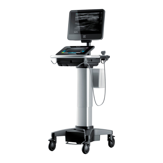
Such behavior could indicate a hardware failure. Contact FUJIFILM SonoSite Technical Support. About the system The SonoSite X-Porte is a portable device that acquires and displays high-resolution, real-time ultrasound images. Features available depend on your system configuration, transducer, and exam type. - Page 12 Figure 2-1 X-Porte front view Figure 2-2 X-Porte rear view 1. Clinical monitor, 2. Touch panel, 3. Platform, 1. Ports on dock, 2. Power cord 4. Hook (4), 5. Transducer connector, 6. Locking connector, 3. Battery charge wheel (4), 7. Height-adjustment pedal, indicator, 4.
-
Page 13: Accessories And Peripherals
Do not use the system if an error message appears on the clinical monitor. Note Cautions the error code and turn off the system. Call FUJIFILM SonoSite or your local representative. When using AC power, position the system to allow easy access to disconnect it. -
Page 14: Adjusting The Height And Angle
ʘ 3 Check the battery switches; ensure that all three switches are depressed to the symbol, which is the ON position. Note The system will not charge and maintain the batteries if the battery switches are depressed to the ·O symbol, which is the OFF position. 4 Reconnect the system to AC power. -
Page 15: Usb Devices
To adjust the touch-panel angle Grasping the sides of the touch panel, pull it forward or push it backward to the desired angle. To collapse the clinical monitor Always collapse the clinical monitor before system transport. 1 Adjust the touch panel angle to the lowest position. 2 Grasping the clinical monitor on both sides, align it squarely above the touch panel. -
Page 16: General Interaction
2 Remove the USB memory stick from the port. General interaction Clinical monitor FUJIFILM SonoSite does not recommend using a monitor other than the clinical WARNINGS monitor provided by FUJIFILM SonoSite. Only the images presented on the clinical monitor are validated for the intended use of the device. - Page 17 The clinical monitor displays the ultrasound image as well as details about the exam and system status. Figure 2-4 Clinical monitor layout Patient header System status area Measurement and calculation area Imaging mode or modes, controls selected Ultrasound image Depth scale Selected transducer, exam type, and MI Orientation marker and TI values...
-
Page 18: Vga Or Digital Video Output
Check the electrical safety of your system with a trained biomedical engineer prior to use. FUJIFILM SonoSite does not recommend using a monitor other than the clinical WARNINGS monitor provided by FUJIFILM SonoSite. Only the images presented on the clinical monitor are validated for the intended use of the device. - Page 19 Use these gestures to perform these actions: Table 2-1: Gestures and actions Gesture Action Swipe Steer D-line (linear transducers only) Steer color box (linear transducers only) Scroll through pages in forms, such as the patient form, worksheets, and thumbnails in Review Select previous or next images in full-screen Review Drag Adjust depth or gain...
-
Page 20: Onscreen Keyboard
Table 2-1: Gestures and actions (continued) Gesture Action Freeze Adjust depth Select calipers Select image in dual Select mode in split screen (2D, D-line, or Doppler trace) Select control Double-tap With two or more fingers, double-tap to freeze or unfreeze Double-tap with one finger in the zoom box to zoom Double-tap with one finger on a live zoomed image to unzoom Pinch or... -
Page 21: Preparing Transducers
Some gels and sterilants can cause an allergic reaction on some individuals. Cautions To avoid damage to the transducer, use only gels recommended by FUJIFILM SonoSite. Using other gels can damage the transducer and void the warranty. If you have questions about gel compatibility, contact FUJIFILM SonoSite or your local representative. - Page 22 2 Insert the transducer connector into one of the three TTC connector ports on the bottom of the TTC. 3 Make sure that the connector is firmly seated, and then turn the latch handle counterclockwise. 4 Press the latch handle up, securing the transducer connector to the TTC. 2-12 Getting started...
- Page 23 To connect a transducer to the system (without a TTC) If the TTC is not installed on your system, you can connect one transducer directly to the system. 1 Pull the transducer latch up, and rotate it clockwise. 2 Insert the transducer connector into the transducer port underneath the stand platform. 3 Make sure that the connector is firmly seated, and then turn the latch handle counterclockwise.
-
Page 24: Selecting A Transducer And Exam Type
To remove a transducer Caution To avoid equipment damage that could lead to image quality degradation, do not disconnect a transducer while it is in use. Either freeze the image or switch to another transducer before disconnecting. 1 Pull the transducer latch up, and rotate it clockwise. 2 Pull the transducer connector away from the system. - Page 25 Make sure you unscrew the D2xp stabilization handle before moving the transducer from its parked position. Needle guide-capable. For more information, refer to Using CIVCO Products with FUJIFILM SonoSite Systems. For more information refer to the TEExp Transducer User Guide, included with the TEExp transducer.
- Page 26 Make sure you unscrew the D2xp stabilization handle before moving the transducer from its parked position. Needle guide-capable. For more information, refer to Using CIVCO Products with FUJIFILM SonoSite Systems. For more information refer to the TEExp Transducer User Guide, included with the TEExp transducer.
- Page 27 Make sure you unscrew the D2xp stabilization handle before moving the transducer from its parked position. Needle guide-capable. For more information, refer to Using CIVCO Products with FUJIFILM SonoSite Systems. For more information refer to the TEExp Transducer User Guide, included with the TEExp transducer.
- Page 28 Make sure you unscrew the D2xp stabilization handle before moving the transducer from its parked position. Needle guide-capable. For more information, refer to Using CIVCO Products with FUJIFILM SonoSite Systems. For more information refer to the TEExp Transducer User Guide, included with the TEExp transducer.
-
Page 29: Gel
Make sure you unscrew the D2xp stabilization handle before moving the transducer from its parked position. Needle guide-capable. For more information, refer to Using CIVCO Products with FUJIFILM SonoSite Systems. For more information refer to the TEExp Transducer User Guide, included with the TEExp transducer. -
Page 30: Sheaths
After use, remove and discard the single-use sheath, and clean and disinfect the transducer using a FUJIFILM SonoSite-recommended disinfectant. See the cleaners and disinfection document available at www.sonosite.com... - Page 31 Figure 2-6 Back of system with second dock configuration: 1. USB 2. USB 3. MicroSD - DVR software upgrade 4. USB storage - DVR 5. VGA out 6. Ethernet Each connector has a symbol that describes its use: Ethernet MicroSD - DVR software upgrade USB storage - DVR VGA out Digital video in...
-
Page 32: Battery Charge Indicator
Connect the system to AC power when the battery charge is low. Cautions Periodically check to make sure that the battery charges fully. If the battery fails to charge fully, contact FUJIFILM SonoSite Technical Support (see “Getting help” on page 1-2). -
Page 33: Visual Guide Videos
Figure 2-7 Battery switches in off positions Visual Guide videos The Visual Guide library contains animated 3D videos that describe scanning techniques, terminology, and more. Scanning is active while a video plays, so you can practice scanning techniques in conjunction with the visual guides. -
Page 34: Intended Uses
Figure 2-8 A Visual Guide video Note Some Visual Guide videos may display incorrect representations of the X-Porte user interface due to using different versions of the software. To play a Visual Guide video 1 Display the Visual Guide screen by doing one of the following: Tap LEARN on the startup screen. - Page 35 WARNING To prevent misdiagnosis, do not use the ECG trace to diagnose cardiac rhythms. The FUJIFILM SonoSite ECG option is a non-diagnostic feature. Gynecology and infertility imaging applications You can assess the uterus, ovaries, adnexa, and surrounding anatomical structures for the presence or absence of pathology transabdominally or transvaginally.
- Page 36 You can use the system for ultrasound guidance in biopsy and drainage procedures, vascular line placement, and peripheral nerve blocks. Contraindications The SonoSite X-Porte ultrasound system has no known contraindications. 2-26 Getting started...
-
Page 37: Setting Up The System
Setting up the system System Settings is where you customize the system and set preferences. Not all system settings are available if you log in to the system Notes as a guest (see “Logging in” on page 3-5). Reset functions are provided on some system settings pages. For example, you can reset the More Controls window for your user profile to the factory default. -
Page 38: About Security Settings
Managing the Administrator account To log in as Administrator The default Administrator login name is Administrator. If you don't have the administrator password, contact FUJIFILM SonoSite (see “Getting help” on page 1-2). WARNING Restoring an administrative password will result in the deletion of data. Back up all data prior to resetting the administrative password. -
Page 39: Protecting Patient Information
4 To ensure security, choose a password that contains uppercase characters (A-Z), lowercase characters (a-z), and numbers (0-9). Passwords are case-sensitive. 5 Tap Save. Protecting patient information To require user login You can set the system to require a user name and password at startup. If you require user login, you also need to set up user accounts (see “Adding and managing user accounts”... - Page 40 To add a new user Note Once you add a new user, you cannot edit the user’s name. 1 On the Administration Login settings page, log in as a user with administrative privileges. 2 Tap New. 3 Under User Information, fill in the Name, Password, and Confirm text boxes. 4 To ensure security, choose a password that contains uppercase characters (A-Z), lowercase characters (a-z), and numbers (0-9).
-
Page 41: Logging In
5 Tap Done. To delete a user 1 On the Administration Login settings page, log in as a user with administrative privileges. 2 Select the user under User List. 3 Tap the delete icon. 4 Tap Yes. 5 Tap Done. Logging in If user login is required, the user login screen appears when you turn on the system (see “To require user... -
Page 42: Audio Settings
Audio settings On the Audio settings page, you can specify sound settings and adjust the volume for beeps and clicks. To display the Audio settings page 1 Tap MORE, and then tap System Settings. 2 Tap Audio in the list on the left. Audio To specify sound settings ... -
Page 43: Cardiac Calculations Settings
You can create up to five custom measurements that appear in the obstetrics calculations lists, in the list of custom measurements in Calculations settings, and in the obstetric report. You can create custom measurements on the system or in the SonoSite X-Porte OB Custom Table Editor, a Microsoft Excel file available at www.sonosite.com. - Page 44 To create custom obstetrics measurements and tables in the OB Custom Table Editor You can set up custom tables of up to 120 entries (age tables) or 210 entries (growth tables). Before you use the SonoSite X-Porte OB Custom Table Editor, make sure that your computer meets the following minimum requirements: Windows Windows Vista, 32-bit or 64-bit, or later...
- Page 45 Values in the Value column and the totals of the values in the Age (weeks) and Age (days) columns must increase. A graphical representation of the values you enter appears to the right of the cells in each tab. Note If you create a custom measurement with a name that matches the name of a custom measurement already on the system, the system overwrites the custom measurement on the system with the new custom measurement when you...
-
Page 46: Cda Report Settings
To view obstetric calculations tables 1 On the Calculations setup page, tap Tables. 2 Select the desired table type and measurement/author. Deleting custom obstetric measurements and tables You cannot modify or delete system-defined obstetric tables. To delete a custom obstetric measurement 1 End the current exam. -
Page 47: Connectivity Settings
2 Tap CDA Report in the list on the left. CDA Report To configure a CDA profile Required fields are marked with asterisks. 1 On the CDA Report settings page, tap Config. 2 On the CDA Report page, tap New. 3 To change the profile name, type a new profile name in the System/Author ID box. -
Page 48: Importing And Exporting Connectivity Settings
DICOM ..................................3-13 Importing and exporting connectivity settings You can import and export all location and connectivity settings from and to another SonoSite X-Porte system. These settings include DICOM configuration data for locations, wireless settings, archivers, printers, storage commit servers, worklist servers, and MPPS servers. -
Page 49: Dicom
Export exam data as DICOMDIR files to a USB storage device (see “USB settings” on page 3-36). The system conforms to the DICOM standard as specified in the Sonosite X-Porte DICOM Conformance Statement, available at www.sonosite.com. The Sonosite X-Porte DICOM Conformance Statement provides information about the purpose, characteristics, configuration, and specifications of the network connections supported by the system. -
Page 50: Configuring The System For Dicom Transfer
Ethernet or wirelessly. To connect to the network by Ethernet The SonoSite X-Porte ultrasound system must be connected to a standard Ethernet 10/100/1000 network. Devices connected to the system’s Ethernet port must comply with the IEC 60601-1 or IEC 60950 standards. - Page 51 1 Connect the Ethernet cable to the Ethernet port on the back of the dock (see “Ports” on page 2-20). With the system on, the LAN link light (green LED) next to the Ethernet connector indicates physical connection to the network. 2 See “DICOM configuration pages”...
-
Page 52: Dicom Configuration Pages
DICOM configuration pages The DICOM configuration pages are as follows: Location Configuration for network settings, including settings for a wireless network connection. Also specifies which devices you want to associate with that network. For example, configure a location called “Office,” and then associate a printer and archiver with it. You can configure up to eight locations (see “Associating devices with locations”... - Page 53 Configuration setup fields Location Required fields are marked with asterisks. Name Unique network name for the ultrasound system. The default is SonoSite. Alias Name that identifies the network location of the ultrasound system. AE Title DICOM Application Entity Title. Port Device port number.
-
Page 54: Index
Network Name (SSID) Network Name Service Set Identifier for the router. Security Policy Security type that authenticates the network: Open No security. WEP or Shared WEP The following fields appear: Encryption Encryption key type (64 bit or 128 bit) Key index WEP key index 1-4. Network location where a specific key is stored. Key WEP key value used to encrypt data. - Page 55 User Name Name of designated user. Client Certificate Select from the list of client certificates installed on the system. Private Key One of a pair of keys (public and private) that is provided only to the requestor and never shared. Private Key Password A unique combination of letters and symbols that allows user access.
- Page 56 Ping Tap to determine whether the IP address is accessible. The system displays OK or Failed. Exclude Video Clips If the check box is selected, only images (no video clips) are transferred. Available only if Image Type is set to Ultrasound. Include CDA Select this check box to send the CDA report to the archiver.
- Page 57 Film Type Film medium supported by the printer. Destination Location film is placed after it is printed. Format Number of columns and rows in the image printout. Orientation Film layout. Settings Defines how images are sent to the printer, either as Color (RGB) or Monochrome images. Copies Number of copies to print for each image.
- Page 58 Alias Name that identifies the network location of the Storage Commit server. AE Title DICOM Application Entity Title. IP Address Unique identifier of the storage commitment server. Port Device port number. IP port 104 is typically assigned for DICOM. Ping Tap to determine whether the IP address is accessible.
-
Page 59: Associating Devices With Locations
Occurs Every In an automatic query, length of time between automatic updates. Start Time In an automatic query, start time for the automatic update (displayed in 24 hour time). Ping Tap to determine whether the IP address is accessible. The system displays OK or Failed. MPPS Required fields are marked with asterisks. - Page 60 1 Tap MORE, and then tap System Settings. 2 Tap Connectivity in the list on the left. 3 On the Connectivity setup page, tap DICOM Setup. 4 In the Location list, select the location of the system. 5 In the list of devices, check the box next to one or more archivers, printers, or worklist servers. You can select a maximum of two printers, four archivers, and one worklist server for each location.
-
Page 61: Date And Time Settings
To verify the connection status of devices 1 On the Connectivity setup page, tap DICOM Setup. 2 Tap Verify to confirm that the associated devices are connected. (If Verify is unavailable, check cable and wireless connections. Restart the system if you changed configuration. If the problem continues, see your system administrator.) The connection status of the devices appears in the Status column: Failed DICOM cannot communicate with the device. -
Page 62: Display Information Settings
Display Information settings On the Display Information settings page, you can specify which details appear on the clinical monitor during imaging. To display the Display Information settings page 1 Tap MORE, and then tap System Settings. 2 Tap Display Information in the list on the left. Display Information To specify details that appear on the clinical monitor ... -
Page 63: Network Status Settings
2 Tap Logs in the list on the left. Logs To export a log Caution To avoid losing data from or damaging the USB memory stick, do not remove the USB memory stick or turn off the ultrasound system while exporting. In addition, do not bump or apply pressure to the USB memory stick while it is connected to the system. -
Page 64: Power And Battery Settings
2 Tap Network Status in the list on the left. Network Status Related topics Connectivity settings ............................. 3-11 DICOM ..................................3-13 Power and Battery settings On the Power and Battery settings page, you can specify the period of inactivity before the system goes into sleep mode or turns off. -
Page 65: General Preferences
To display the Presets settings page 1 Tap MORE, and then tap System Settings. 2 Tap Presets in the list on the left. Presets General preferences To set general preferences On the Presets settings page, select from the following lists: Note Changing Doppler Scale or Units clears all measurements and calculations for the current exam. -
Page 66: Labels
Drag the Touch Panel Brightness slider. The range is 2-10. Labels You can customize predefined labels, create new labels, delete labels, and set the preference for clearing labels when unfreezing images. To manage predefined labels Each exam type supports up to 35 predefined labels. 1 On the Presets settings page, tap Labels. - Page 67 (User-defined exam types only) To rename the exam type, tap the exam type name and type a new name. (User-defined exam types only) To delete the exam type, tap the delete icon. To show or hide the exam type in the transducer & exam types list, tap the check box next to the exam type in the column.
-
Page 68: User Profile Settings
2 Tap Save Exam Type. If this control is hidden, tapping More Controls displays it. 3 In the Save User-Defined Exam window, tap the exam type and tap Update. The current settings overwrite the previously saved settings. User profile settings To specify a startup mode You can specify what mode the system will be in when you start it, end an exam, or log in. -
Page 69: Importing And Exporting
To configure custom controls By default, the controls that appear next to the Freeze control in live imaging are Print, Save Image, Save Video Clip, and End Exam. The Auto gain control appears just above End Exam. You can specify the function of these controls. 1 On the Presets settings page, tap User Profile. -
Page 70: Routing Selections
To import or export When you import from the Presets settings page, all system preferences on the system are replaced with the imported preferences. When you export from the Presets settings page, all system preferences on the USB memory stick are replaced with the exported preferences. 1 Insert a USB memory stick. -
Page 71: Specifying Educational Dicom Archivers
You can associate an exam with a routing selection during an exam or after ending an exam. Note If you specify an archiver as an educational archiver (see “To specify an educational archiver” on page 3-36), exams that aren't associated with a routing selection will not transfer to any archiver. -
Page 72: System Information Settings
To specify an educational archiver Note If you specify an archiver as an educational archiver, exams that aren't associated with a routing selection will not transfer to any archiver. To associate an exam with a routing selection once the exam has ended, see “To associate a routing selection after an exam”... -
Page 73: Limitations Of Jpeg Format
DICOM Export creates DICOMDIR files readable by a DICOM reader. DICOM is an optional feature. Multimedia Export organizes files in a standard folder structure. Video clips export in MJPEG video saved as AVI. To view them, FUJIFILM SonoSite recommends Windows Media Player or QuickTime 7.0 or later. -
Page 74: Efilm Lite Image-Viewer
JPEG settings: Setting Quality Level 100%; The difference between the compressed and uncompressed image is near 0. Medium 90%; Generally loss only to high frequency content (some degradation occurs at the edges of structures in the image). High 75%; General loss of detail Note The ratio of the image size without compression to the image size with compression is dependent on the content of the image... - Page 75 Setting up the system 3-39...
- Page 76 3-40 Setting up the system...
-
Page 77: Imaging
Imaging This section describes imaging with the X-Porte ultrasound system. Imaging modes This section describes the imaging modes available on the ultrasound system. X-Porte offers four different imaging modes: 2D (see “2D” on page 4-2), Color, (see “Color” page 4-3), Doppler (see “Doppler”... -
Page 78: M Mode
2D is the system's default imaging mode. The system displays echoes in two-dimensional view by assigning a brightness level based on the echo signal amplitude. To achieve the best possible image quality, properly adjust the gain, depth settings, viewing angle, exam type, and display brightness. Also, select an optimization setting that best matches your needs. -
Page 79: Color
If Update is hidden, tapping More Controls displays it. c Do any of the following: Tap Stop and Start to stop and start the M Mode sweep. Tap Sweep Speed and then tap a sweep speed: Fast, Medium, or Slow. If this control is hidden, tapping More Controls displays it. -
Page 80: Doppler
Tap Steering and select an angle. 3 Adjust controls as needed. See “Controls in Color” on page 4-12. Related topics Controls in Color ............................... 4-12 Doppler Doppler imaging is a display of a spectrum of flow velocities over time. The amplitude of the signal is indicated as a shade of gray. -
Page 81: Dual
Drag the angle cursor to the correct angle. Tap one of the preset angles on the screen: +60°, 0°, or -60°. Tap Angle Correct. If this control is hidden, tapping More Controls displays it. 4 In the Cardiac exam type only, select one of the following modes: PW - Pulsed wave Doppler CW - Continuous wave Doppler TDI - Tissue Doppler Imaging... -
Page 82: Imaging Controls
Tap Update to switch between the right-hand and left-hand images. If this control is hidden, tapping More Controls displays it. When you transition to live imaging, the settings are those of the last imaging state. 3 Adjust controls as needed. See “Controls in 2D”... - Page 83 Available controls depend on the imaging mode, system configuration, and whether the image is live or frozen. To access a control in the More Controls window 1 Tap More Controls. 2 If necessary, tap the imaging mode (for example, 2D) at the top of the More Controls window. (The control for the active imaging mode is blue.) Multiple imaging modes are available if one of them includes another.
-
Page 84: Controls In 2D
Controls in 2D To specify which controls appear in the Controls bar, see “Imaging controls” on page 4-6. Some controls appear only when the image is frozen. Table 4-1: 2D controls Available in Button name Description Live Frozen Tap this control to turn Tissue Harmonic Imaging (THI) on (highlighted icon) or off (dimmed icon). - Page 85 Using CIVCO Products with FUJIFILM SonoSite Systems. Only compatible with Full sector. Displays ECG trace options. ECG is available only on the cardiac exam type.
- Page 86 Table 4-1: 2D controls (continued) Available in Button name Description Live Frozen Target Depth Measures the distance from the skin line to a specified point on the image. For instructions, see “Measuring” on page 5-1. Label Provides tools that let you place text, pictographs, and arrows onto an image.
- Page 87 When using the Centerline feature as a reference during a freehand procedure, be aware that the centerline represents only the center of the ultrasound image and is not an accurate predictor of the path the needle will take. Ensure orientation marks on the screen and transducer are on the same side...
-
Page 88: Controls In Color
Imaging modes ................................4-1 Imaging controls ................................. 4-6 Controls in Color ..............................4-12 Controls in M Mode ............................... 4-14 Controls in Doppler ..............................4-16 Controls in Color To specify which controls appear in the Controls bar, see “Imaging controls” on page 4-6. Some controls appear only when the image is frozen. - Page 89 Table 4-2: Color controls (continued) Available in Button name Description Froze Live Steering (Linear transducers only) Determines the angle of the color box (see “Imaging controls” on page 4-6), saving work in repositioning the transducer. If adding Doppler, see “Controls in Doppler” on page 4-16.
-
Page 90: Controls In M Mode
Table 4-2: Color controls (continued) Available in Button name Description Froze Live Calcs “About calculations” on page 5-8. Acute Care The Acute Care calculations are part of the licensed Acute Care feature. See “Acute Care calculations” on page 5-45. Related topics Color .................................... - Page 91 Table 4-3: M Mode controls (continued) Available in Button name Description Froze Live Sweep Available when displaying the M Mode sweep. Sets the sweep Speed speed. Tap this control and then select the speed: Slow, Med, or Fast. Display Lets you control the format of the 2D and sweeping images. Tap Format this control, and then tap the specified format: 1/3 2D, 2/3 Sweep...
-
Page 92: Controls In Doppler
Controls in Doppler In Doppler imaging, you can adjust controls in D-line (see Table 4-4 on page 4-16) and in scrolling Doppler (see Table 4-5 on page 4-18). To specify which controls appear in the Controls bar, see “Imaging controls” on page 4-6. - Page 93 Table 4-4: Controls in D-line (continued) Available in Button name Description Live Frozen Display Format Lets you control the format of the 2D and sweeping images. Tap this control, and then tap the specified format: 1/3 2D, 2/3 Sweep 1/2 2D, 1/2 Sweep 2/3 2D, 1/3 Sweep Side by Side Full 2D, Full Sweep...
- Page 94 Table 4-5: Controls in scrolling Doppler Available in Button name Description Live Frozen PW/CW/TDI Select PW (pulsed wave Doppler), CW (continuous wave Doppler), or TDI (Tissue Doppler Imaging). CW and TDI are available only in the Cardiac exam type. Steering Linear transducers only.
- Page 95 Table 4-5: Controls in scrolling Doppler (continued) Available in Button name Description Live Frozen Baseline Sets the baseline position. Tap this control, and then tap Up or Down. Invert Tap on (highlighted icon) to switch the displayed direction of the flow, which helps to reduce the need to reposition the transducer.
-
Page 96: Adjusting Depth And Gain
Table 4-5: Controls in scrolling Doppler (continued) Available in Button name Description Live Frozen Calcs “About calculations” on page 5-8. Heart Rate Provides calipers to measure heart rate. Slope Provides calipers to measure slope and slope-related measurements. Only available in the cardiac exam type. Related topics Doppler .................................... -
Page 97: Gain
Drag the depth scale. Gain Gain refers to amplifying the intensity of the returning sound waves on the screen display. Increasing the gain brightens the image. Decreasing the gain darkens the image. There are two ways to adjust gain: automatically and by using the gain sliders. To adjust gain automatically ... -
Page 98: Freezing, Viewing Frames, And Zooming
Freezing, viewing frames, and zooming Freezing the image Before performing certain tasks, such as viewing the cine buffer or measuring, you stop live imaging or freeze the image. When you freeze the image, you can perform calculations. See “About calculations” on page 5-8. -
Page 99: Zooming In On The Image
Drag the slider. Right moves forward, and left moves backward. M Mode: While the slider bar represents the complete set of collected imaging data, the scrolling display shows only one cycle of imaging data at a time. The green CINE marker ( ) indicates a single column on the scrolling display, which corresponds in time to the displayed image. -
Page 100: Visualizing Needles
To zoom in on a frozen image 1 Tap Zoom. If this control is hidden, tapping More Controls displays it. 2 Do any of the following: To unzoom, tap Off. Drag the slider. To unzoom, drag the slider to 1.0. 3 (Optional) Pan the image by dragging left, right, up, or down. - Page 101 X-Porte features Steep Needle Profiling technology, which can facilitate needle guidance during catheter placement and nerve-block procedures. This technology enhances linear structures within an outlined area on the screen. Linear structures are best enhanced when perpendicular to the angle guide (Figure 4-3 page 4-25).
- Page 102 Figure 4-4 Steep Needle Profiling with a curved array Steep Needle Profiling is available in 2D full-screen imaging only and on the following exam types. Table 4-6: Steep Needle Profiling-compatible exam types Transducer Arterial Breast Musculoskeletal Nerve Small Parts Venous C35xp C60xp HFL38xp...
-
Page 103: Needle Size And Angle
Curved transducer: Use the following table to determine the needle angle setting to use. Needle angles are measured in relation to the surface of the transducer. Table 4-7: Shallow, Medium, and Steep setting angles Range for Shallow Range for Steep Transducer Range for Medium setting setting... -
Page 104: Labeling Images
Labeling images You can label live, frozen, or saved images. You can label in full-screen 2D, full-screen trace, dual, or duplex. You can place text (including predefined labels), arrows, and pictographs. To set preferences for labels, including predefined text labels, see “Labels”... -
Page 105: Adding Arrows
4 Make changes as needed: To edit the text, select it in the Label list and tap Edit. To remove the text, select it in the Label list and tap Delete. To remove all text labels, tap Remove All Text in the Label list. Adding arrows You can add an arrow graphic to point out a specific part of the image. -
Page 106: Setting The Home Position
Setting the home position The home position is the position in which the system places labels by default. To reset the home position 1 Place text on an image. 2 Drag the label to the desired home position. 3 Tap Set Home in the Label list. Labeling during review You can label images during review. -
Page 107: Entering Patient Information
To delete the Mark Out box, select the Mark Out box in the Mark Out list and then tap Delete. The system displays the image or video clip in full-screen mode. 5 Tap Save. The system saves the labeled image to the exam. 6 Tap Done to exit labels and return to review. -
Page 108: Entering Patient Information Manually
Tap Cancel to discard your changes. Entering patient information manually To enter patient information manually 1 End the previous exam (see “Ending the exam” on page 4-35). 2 Tap PATIENT. 3 Tap a text box, and fill in the fields (see “Patient form fields”... - Page 109 3 To sort the worklist, tap a column heading to sort by. By default, the worklist sorts in ascending order. 4 Do any of the following: To select one or more procedures for the patient, tap the procedure or procedures. You can select multiple procedures only for the same patient.
- Page 110 The following table shows the parameters used for worklist queries. You set parameters on the worklist configuration page (see “DICOM” on page 3-13). Table 4-8: Query parameters Manual Patient Manual Update from Automatic Query Query Worklist Update Patient Data Date Range This Device Only Automatic Query On/Off Occurs Every...
-
Page 111: Ending The Exam
Ending the exam Note Although you cannot add images and video clips to a patient exam that is ended, you can automatically start a new patient exam that has the same patient information. See “To append images and video clips to a patient exam” page 4-40. - Page 112 Exam The exam types available depend on transducer (see “Selecting a transducer and exam type” page 2-14). An asterisk next to an exam type indicates that it is a system-defined exam type (see “Customizing exam types” on page 3-31). BP (Cardiac or Arterial exam) Blood Pressure HR (Cardiac or Arterial exam) Heart Rate.
- Page 113 User Reading Doctor Referring Doctor Acute Care Worksheets If the Acute Care Worksheets licensed option is installed on your system, the patient form displays these fields, which also appear in the patient's Acute Care worksheet: MR # Medical record number. Clinical Category The exam's clinical category.
-
Page 114: Images And Clips
Scheduled Procedure: Protocol Protocol for the selected procedure Scheduled Procedure: Meaning Definition of the selected procedure Performed Procedure: Code Desired procedure Performed Procedure: Edit Enables you to modify the Code list Performed Procedure: Meaning Definition of the performed procedure Additional Worklist Query Parameters: Modality Procedure types Additional Worklist Query Parameters: Requested Procedure ID The procedure ID... - Page 115 The user who performed the exam The number of images and video clips saved with the exam The archive status of the exam The export status of the exam To display the patient list 1 Do one of the following: Tap REVIEW, and then tap Patient List.
- Page 116 To append images and video clips to a patient exam Although you cannot add images and video clips to a patient exam that is ended, you can automatically start a new patient exam that has the same patient information. Depending on your archiver, the two exams appear as one study when exported or archived.
-
Page 117: Printing Images
Label an image or a frame from a video clip (see “Labeling during review” on page 4-30). View the report (see “Worksheets and reports” on page 5-52). Delete an image or video clip: select the image or video clip, and then tap Delete. 5 Return to the patient list by tapping Patient List, or return to imaging by tapping Exit Review. - Page 118 You can archive exams from the patient list to a DICOM archive server or print them to a DICOM printer. You can export exams to a USB memory stick. Note The system does not support software-encrypted USB memory sticks. Archiving exams If you have configured the system for DICOM transfer, the system automatically archives saved images and video clips, along with the patient report, to DICOM devices.
- Page 119 To display information about an exam You can display information about an exam, including transfer details. 1 Tap REVIEW. 2 Tap Patient List. 3 In the patient list, select the exam. 4 Tap Info. To manually archive exams 1 Verify the following: The correct location is selected (see “To specify the system location”...
-
Page 120: Saving Images And Video Clips
To export patient exams manually to a USB memory stick 1 Specify the file format for exported images (see “USB settings” on page 3-36). 2 Tap REVIEW. 3 Tap Patient List. 4 Connect a USB memory stick (see “To connect a USB memory stick for importing or exporting” page 2-6). - Page 121 Saving images To avoid mixing images saved from multiple patients, make sure that the patient ID is displayed before you save an image. See “Entering patient information” on page 4-31 and “Display Information settings” on page 3-26. To save an image If the Save Image or Save Image &...
- Page 122 3 Tap Done. To capture and save a video clip 1 Make sure that video clips settings are set as desired. See “To set video clips controls” on page 4-45. 2 Tap Save Video Clip. Note You can also configure the footswitch to save a video clip (see “User profile settings”...
-
Page 123: Dvr Recording
DVR recording You can record video displayed on the clinical monitor to a USB memory stick inserted into the DVR USB port. Clips save as MP4 files. You can copy the recordings to another device. Note The system does not support software-encrypted USB memory sticks. When recording to a USB memory stick, make sure the memory stick is empty of other data, files, or folders before inserting it into the system. -
Page 124: Image Gallery
3 Display the USB memory stick's contents and copy the recordings (MP4 files) to the device. Note If video recorded from the DVR is too bright when you view it on a personal computer, you can adjust the video color settings on your PC’s monitor. For example, change the Dynamic Range to Full. -
Page 125: Ecg
9 Tap Export. The ECG feature requires an optional FUJIFILM SonoSite ECG module. ECG is available only on the cardiac exam type. WARNING To prevent misdiagnosis, do not use the ECG trace to diagnose cardiac rhythms. - Page 126 Use only accessories recommended by FUJIFILM SonoSite with the system. Cautions Connecting an accessory not recommended by FUJIFILM SonoSite can damage the system. If you defibrillate a patient while the ECG module is connected to the system, the ECG signal may display incorrectly, and the ECG module may need to be replaced.
- Page 127 To adjust the value of the ECG gain, drag the Gain slider. To set the ECG scroll speed, select Slow, Medium, or Fast under Sweep Speed. If the Doppler or M Mode trace is active, the ECG scroll speed matches the sweep speed for the trace. To move the ECG trace up or down vertically on the image, tap Up or Down under Position.
- Page 128 4-52 Imaging...
-
Page 129: Measurements And Calculations
Measurements and calculations This section provides information about measurements, calculations, worksheets, and reports. Measuring X-Porte offers several types of measurements. You can perform independent measurements, or you can perform a measurement and then assign it to a calculation (see “Assigning measurements to calculations” page 5-8). -
Page 130: Viewing And Deleting Measurement Results
Viewing and deleting measurement results The current measurement result appears on the left side of the touch panel under Measure. To assign it to a calculation, see “Assigning measurements to calculations” on page 5-8. If you perform multiple measurements, tapping an entry under Measure highlights the corresponding calipers on the image. -
Page 131: Basic Measurements In M Mode
2 Drag the caliper to the start point. After lifting your finger from the screen, a pencil icon appears, indicating that the start location is set and you can begin your trace. 3 Drag the caliper around the area you want to trace. To make a correction, trace backward on the dotted line. -
Page 132: Basic Measurements In Doppler
2 Drag the caliper to the peak of the heartbeat. A second vertical caliper appears. 3 Drag the second caliper to the peak of the next heartbeat. Saving the heart rate measurement to the patient report overwrites any heart rate entered on the patient form. - Page 133 2 Drag the caliper to a peak velocity waveform. To measure Velocities, Elapsed Time, Ratio, and Resistive Index (RI) or Acceleration 1 On a frozen Doppler spectral trace, tap Velocity. A single caliper appears. If this control is hidden, tapping More Controls displays it. 2 Drag the caliper to a peak systolic waveform.
- Page 134 Performing Doppler trace measurements Trace measurements depend upon the exam type and measurement tool. Table 5-1: Doppler trace measurements Exam type Tool OB/Gyn/ Cardiac Arterial TCD/Orbital Lung Other Venous VMax VMax VMax VMax VMax Manual VMax Trace PI PI PI PI PGMax...
- Page 135 2 Drag the caliper to the beginning of the desired waveform. After lifting your finger from the screen, a pencil icon appears, indicating that the start location is set and you can begin your trace. 3 Drag the caliper to trace the waveform. To make a correction, trace backward on the dotted line.
-
Page 136: Assigning Measurements To Calculations
Assigning measurements to calculations You can assign a measurement to a calculation that includes that measurement type. When you assign a measurement to a calculation, a checkmark appears next to the measurement indicating that it has been successfully saved. To assign a measurement to a calculation 1 After performing the measurement, select it, and tap Calcs. -
Page 137: Overview
Volume calculations Volume Flow calculations (available in abdominal and arterial exam types only) Percent reduction calculations Specialized calculations that are specific to one exam type: Abdominal calculations Arterial calculations Cardiac calculations Gynecology calculations Obstetrical calculations Small Parts and MSK (musculoskeletal) calculations Acute Care calculations, included with the Acute Care worksheets licensed feature. - Page 138 To save calculation measurements When you save a measurement, a checkmark appears next to the measurement, indicating that the value has been saved. With one or more measurements on the screen, do any of the following: Save the selected measurement: Tap under the measurement name.
- Page 139 Percent reduction calculations To avoid incorrect calculations, verify that the patient information, date, and WARNINGS time settings are accurate. To avoid misdiagnosis or harming the patient outcome, start a new patient form before starting a new patient exam and performing calculations. Starting a new patient form clears the previous patient’s data.
-
Page 140: Volume Calculation
The percent diameter reduction result appears on the clinical monitor and saves to the patient report. Volume calculation To avoid incorrect calculations, verify that the patient information, date, and WARNINGS time settings are accurate. To avoid misdiagnosis or harming the patient outcome, start a new patient form before starting a new patient exam and performing calculations. -
Page 141: Exam-Based Calculations
Consider the following factors when performing volume flow measurements: You should follow current medical practice for volume flow calculation applications. The accuracy of the volume flow calculation largely depends on the user's measurement technique. The factors identified in the literature that affect the accuracy are as follows: Using the diameter method for 2D area Precision in placing the caliper Difficulty ensuring uniform insonation of the vessel... -
Page 142: Arterial Calculations
2 On the calculation list, tap Volume Flow. Steps 3 and 4 can be done in either order. 3 Measure blood vessel diameter: a On a frozen 2D image, on the Volume Flow menu, tap Diam. b Position the calipers by dragging. c Tap to save the measurement. - Page 143 Table 5-3: Arterial calculations Calculation list Measurement name CCA Right Proximal Middle Distal Bulb ICA Proximal Middle Distal ECA Proximal VA “Considerations” on page on page 5-12 for factors to consider when performing a volume flow calculation. When the Doppler trace is measured, the result includes velocity time integral and time averaged velocity calculations depending upon the trace type.
- Page 144 Table 5-3: Arterial calculations Calculation list Measurement name CCA Left Proximal Middle Distal Bulb ICA Proximal Middle Distal ECA Proximal VA Volume Flow Diam(2D),TAM, TAP, or TAV (Doppler) “Considerations” on page on page 5-12 for factors to consider when performing a volume flow calculation. When the Doppler trace is measured, the result includes velocity time integral and time averaged velocity calculations depending upon the trace type.
- Page 145 a Select the calculation list that contains the measurement name. b Drag the caliper to the peak systolic waveform, and tap Next. A second caliper appears. c Drag the caliper to the end diastole point on the waveform. d Tap under the measurement name.
-
Page 146: Cardiac Calculations
i On a frozen Doppler trace, on the Volume Flow menu, tap TAP (peak). To use a different velocity measurement, tap and then choose either Mean or Manual. Note Using the Mean option will not provide a VTI measurement. ii For Manual, trace the waveform by dragging the calipers. To make a correction, trace backward on the dotted line. - Page 147 Table 5-4: Cardiac calculations and results Calculation list Measurement name (imaging mode) Results EF (2D or M Mode) LVDFS LVDd LVDs LV Vol EF (2D) A4C EF A2C EF A4Cd Biplane EF A4Cs A2Cd A2Cs Right (2D or M Mode) LV FAC RV FAC EDA...
- Page 148 Table 5-4: Cardiac calculations and results (continued) Calculation list Measurement name (imaging mode) Results Diastole (2D or M Mode) LVDFS RVWd RVDd IVSd LVDd LVPWd Systole (2D or M Mode) RVWs RVDs IVSs LVDs LVPWs LVOT D (2D) HR (Doppler) LVOT VTI (Doppler) Ao (2D or M Mode) Ao/LA...
- Page 149 Table 5-4: Cardiac calculations and results (continued) Calculation list Measurement name (imaging mode) Results E-F Slope (M Mode) EPSS (M Mode) MV/MR E (Doppler) Decel (Doppler) A (Doppler) PHT (Doppler) VTI (Doppler) IVRT (Doppler) Adur (Doppler) dP:dT (CW Doppler) MVA (2D) Area AVA (2D) LA A4C (2D)
- Page 150 Table 5-4: Cardiac calculations and results (continued) Calculation list Measurement name (imaging mode) Results AV/LVOT/AI by VMax AVAc by VTI VMax (Doppler) AV VTI (Doppler) LVOT VMax (Doppler) VTI (Doppler) LVOT D (2D) PHT (Doppler) RA pressure TV/TR RVSP TR VMax (Doppler) E (Doppler) A (Doppler) PHT (Doppler)
- Page 151 Table 5-4: Cardiac calculations and results (continued) Calculation list Measurement name (imaging mode) Results Radius (Color) PISA PISA Area Regurgitant Volume MR VTI (Doppler) Ann Diam (2D) MV VTI (Doppler) LVOT Diam (2D) Qp/Qs Qp/Qs RVOT D (2D) LVOT VTI (Doppler) RVOT VTI (Doppler) Left E(MV)/e' ratio...
- Page 152 To calculate Proximal Isovelocity Surface Area (PISA) The PISA calculation requires a measurement in 2D, a measurement in Color, and two measurements in Doppler spectral trace. After all measurements are saved, the result appears in the patient report. 1 Measure from Ann D: a On a frozen 2D image, tap Calcs.
- Page 153 1 On a frozen 2D image or M Mode sweep, tap Calcs. If this control is hidden, tapping More Controls displays it. 2 On the EF or LV calculation list, tap the name of the first measurement you want to take. 3 Position the calipers by dragging.
- Page 154 2 On the Ao/LA calculation list, tap the measurement name. 3 Position the calipers by dragging. 4 Save the calculation: Tap under the measurement name. To calculate Atrial Volumes (Simpson’s Rule) 1 On a frozen 2D image, tap Calcs. If this control is hidden, tapping More Controls displays it. 2 On the calculation list, tap Atrial Vol.
- Page 155 To calculate LV Volume (Simpson’s Rule) Note To calculate Biplane EF, you will need to make all four measurements. 1 On a frozen 2D image, tap Calcs. If this control is hidden, tapping More Controls displays it. 2 Tap the EF calculation list to access the LV Vol EF measurements. 3 To trace each measurement manually: a Under the measurement name, tap the gear icon and select Manual Trace.
- Page 156 4 Using your finger, trace the desired area. To make a correction, trace backward on the dotted line. 5 Do one of the following: To save the measurement and close the trace, tap To close the trace, lift your finger. To calculate LV Mass 1 On a frozen 2D image, tap Calcs.
- Page 157 b In the measurements list, tap Min D. c Measure the diameter with the calipers. d To save the measurements, tap under the measurement name. To measure deceleration time (Decel) 1 On a frozen Doppler spectral trace, tap Calcs. If this control is hidden, tapping More Controls displays it. 2 On the MV/MR calculation list, tap Decel.
- Page 158 2 On the MV/MR, AV/LVOT/AI, TV/TR, or PV calculation list, tap VTI. 3 To trace manually: a Under the measurement name, tap the gear icon and select Manual Trace. b Drag the caliper to the start of the waveform, and lift your finger to start the trace. c Using your finger, trace the waveform.
- Page 159 To calculate Pressure Half Time (PHT) in MV, AI, or TV 1 On a frozen Doppler spectral trace, tap Calcs. If this control is hidden, tapping More Controls displays it. 2 On the MV/MR, AV/LVOT/AI, or TV/TR calculation list, tap PHT. 3 Drag the first caliper to the peak.
- Page 160 5 Save the calculation: Tap under the measurement name. To calculate Aortic Valve Area (AVA) The AVA calculation requires a measurement in 2D and two measurements in Doppler. After the measurements are saved, the result appears in the patient report. 1 In 2D: a On a frozen 2D image, tap Calcs.
- Page 161 1 On a frozen 2D image, tap Calcs. If this control is hidden, tapping More Controls displays it. 2 Do the following to measure from LVOT D and again to measure from RVOT D: a From the Qp/Qs calculations list, select LVOT D or RVOT D. b Position the calipers by dragging.
- Page 162 b To measure LVOT VTI from the Cardiac Output (CO) calculation list: i On a frozen Doppler spectral trace, tap Calcs. If this control is hidden, tapping More Controls displays it. ii From the CO calculation list, tap LVOT VTI. Follow the trace instructions in “To calculate Velocity Time Integral (VTI)”...
-
Page 163: Gynecological Calculations
To calculate Tricuspid Annular Plane Systolic Excursion (TAPSE) TAPSE is used to determine the state of the right ventricular systolic function and to correlate this measurement with the right ventricular ejection fraction. 1 On a frozen M Mode sweep, tap Calcs. If this control is hidden, tapping More Controls displays it. - Page 164 Measuring uterus You can measure uterus length (L), width (W), height (H), and endometrial thickness. If you measure length, width, and height, the system also calculates the volume. To measure uterus 1 On the frozen 2D image, tap Calcs. If this control is hidden, tapping More Controls displays it. 2 On the Uterus list, do the following for each measurement you want to take: a In the Uterus list, tap the measurement name.
- Page 165 2 On the Follicle Right (if measuring the right side) or Follicle Left (if measuring the left side) calculation list, do the following for each measurement you want to take: a Tap the follicle number. If this is the first follicle you are measuring, tap 1. b Position the calipers by dragging.
-
Page 166: Obstetrics Calculations
Obstetrics calculations Make sure that you have selected the Obstetrics exam type and the OB WARNINGS author for the Obstetrical calculation table you intend to use. See “Obstetrics calculations settings” on page 3-7. To avoid incorrect obstetrics calculations, verify with a local clock and calendar that the system’s date and time settings are correct before each use of the system. - Page 167 Table 5-5: Results from system-defined obstetrical measurements and table authors Calculation result Gestational OB measurements Available authors — Gestational Age Hansmann, Nyberg, Tokyo U. Hadlock, Hansmann, Osaka, Tokyo U. Chitty, Hadlock, Hansmann, Osaka, Tokyo U. Hansmann Chitty, Hadlock, Hansmann Hansmann, Tokyo U. APTD Tokyo U.
- Page 168 Table 5-5: Results from system-defined obstetrical measurements and table authors (continued) Calculation result Gestational OB measurements Available authors Estimated Fetal Weight HC, AC, FL Hadlock 1 (EFW) BPD, AC, FL Hadlock 2 AC, FL Hadlock 3 BPD, TTD Hansmann BPD, FTA, FL Osaka U.
- Page 169 To measure gestational growth (2D) For each 2D Obstetrical measurement (except AFI), the system saves up to three individual measurements and their average. If you take more than three measurements, the earliest measurement is deleted. 1 Make sure that the Obstetrics exam type is selected. 2 On the patient form, select LMP or EDD.
- Page 170 (UmbA) (Doppler) 1 Make sure that the Obstetrics exam type is selected. 2 On the patient form, select LMPor EDD. Select Twins if twins. 3 On a frozen Doppler spectral trace, tap Calcs. If this control is hidden, tapping More Controls displays it. 4 Do the following for each measurement you need to take: a On the Doppler Measurements calculations list, tap the measurement name under MCA or UmbA.
- Page 171 Required measurements for MCA or UmbA Table 5-6: MCA or UmbA calculations and results Calculation list Section heading Measurement name Results S/D, RI Doppler Measurements S/D, RI, PI* TAV (or TAP) S/D, RI Umb A S/D, RI, PI* TAV (or TAP) *Calculation requires a trace measurement.
-
Page 172: Small Parts And Msk Calculations
Small Parts and MSK calculations To avoid incorrect calculations, verify that the patient information, date, and time WARNINGS settings are accurate. To avoid misdiagnosis or harming the patient outcome, start a new patient form before starting a new patient exam and performing calculations. Starting a new patient form clears the previous patient’s data. -
Page 173: Acute Care Calculations
An ellipse with calipers appears. b Position and resize the ellipse by dragging its calipers. c Tap Baseline. The baseline appears automatically. d Position the baseline by dragging its caliper. Acute Care calculations To avoid incorrect calculations, verify that the patient information, date, and WARNINGS time settings are accurate. - Page 174 Table 5-7: Acute Care calculations (continued) Calculation list Measurement name (imaging mode) Yolk Sac (2D) Obstetrical Pelvic Gestational Sac (2D) Myometrial Thickness (2D) CRL (2D) BPD (2D) Fetal HR (M Mode) Adnexa Right Ovarian Cyst (2D) Left Ovarian Cyst (2D) Endometrial Stripe (2D) Non-Obstetrical Pelvic Uterine Fibroid (2D)
- Page 175 Table 5-7: Acute Care calculations (continued) Calculation list Measurement name (imaging mode) Gallstone (2D) Biliary Gallbladder Wall (2D) CBD (2D) Transverse Gallbladder (2D) Longitudinal Gallbladder (2D) Right Kidney (2D) Renal/Urinary Tract Kidney Stone Renal Cyst Left Kidney (2D) Kidney Stone Renal Cyst Bladder (2D) Width...
- Page 176 Table 5-7: Acute Care calculations (continued) Calculation list Measurement name (imaging mode) Eye Ocular Right ONSD (2D) Left ONSD (2D) Calculates a gestational age. See “Obstetrics calculations” on page on page 5-38 for related information Uses the selected gestational age table. See “Calculations settings”...
-
Page 177: Transcranial Doppler And Orbital Calculations
Transcranial Doppler and Orbital calculations To avoid injury to the patient, use only an Orbital (Orb) or Opthalmic (Oph) WARNINGS exam type when performing imaging through the eye. The FDA has established lower acoustic energy limits for opthalmic use. The system will not exceed these limits only if the Orbital or Ophthalmic exam type is selected. - Page 178 Table 5-8: Transcranial Doppler and Orbital calculations and results (continued) Calculation list Measurements Results OA Right Transorbital Gate depth Velocity* Siphon Right Submandibular ECICA Gate depth Velocity* FM VA Right Suboccipital Gate depth Velocity* BA Dist BA Mid BA Prox ECVA MCA Dist Left Transtemporal...
- Page 179 Table 5-8: Transcranial Doppler and Orbital calculations and results (continued) Calculation list Measurements Results OA Left Transorbital Gate depth Velocity* Siphon Left Submandibular ECICA Gate depth Velocity* FM VA Left Suboccipital Gate depth Velocity* BA Dist BA Mid BA Prox ECVA *The velocity measurement is labeled either TAM for a manual trace or TAP for an automatic trace .
-
Page 180: Worksheets And Reports
3 Do the following for each measurement you want to take: a From the calculations list, select the measurement. b Drag the calipers to position them. c To save the calculation, tap under the measurement name. Related topics Worksheets and reports ............................5-52 Cardiac calculations .............................. -
Page 181: Report Preview
Report preview To display the report preview 1 Tap WORKSHEETS. 2 (Arterial or Cardiac exam) Tap Summary or Calculations in the Report Preview list. The mean of the detail entries is used in the summary. You can switch between these views as needed. To exit the report preview and return to imaging, tap Done. -
Page 182: Acute Care And Msk Worksheets
To fill out the Obstetrics anatomy checklist You can document reviewed anatomy. 1 In the Obstetrics report preview, tap Anatomy Checklist. 2 Do any of the following: Select the check boxes. Enter the Fetal Lie. Enter the Plac Location and select the grading method (0, I, II, or III) from the corresponding list. Select a Gender. - Page 183 To display an Acute Care or MSK worksheet 1 Tap WORKSHEETS. 2 Tap Acute Care Worksheets or MSK Worksheets. 3 Tap a worksheet in the list. To exit the worksheet and return to imaging, tap Done. To edit an Acute Care or MSK worksheet You can edit worksheets on the system until the exam has ended.
-
Page 184: Printing Reports And Worksheets
Printing reports and worksheets You can print the current page of a report preview or worksheet or the entire report preview or worksheet. To print a report preview or worksheet 1 Display the report preview or worksheet. 2 Do one of the following: To print the entire report preview or worksheet, tap Print All. -
Page 185: Measuring During Review
5 Enter up to 20 headings (for example, procedures). 6 Enter check box items underneath each heading. 7 Tap Save Changes to save changes or Done to exit. Measuring during review You can measure images during an exam or during review, after an exam has ended. You must save to obtain an image with measurements added in review. - Page 186 5-58 Measurements and calculations...
-
Page 187: Measurement References
Measurement references This section provides information about measurement accuracy, publications, and terminology. Measurement accuracy The measurements from the system are of a physical property such as distance for evaluation by the clinician. The accuracy values require that you can place the calipers over one pixel. - Page 188 Full scale for distance implies the maximum depth of the image. An RMI 413a model phantom with 0.7 dB/cm MHz attenuation was used. Full scale for time implies the total time displayed on the scrolling graphic image. FUJIFILM SonoSite special test equipment was used. Measurement references...
-
Page 189: Sources Of Measurement Errors
An RMI 413a model phantom with 0.7 dB/cm MHz attenuation was used. Full scale for time implies the total time displayed on the scrolling graphic image. FUJIFILM SonoSite special test equipment was used. Table 6-3: PW Doppler Mode Measurement and Calculation Accuracy and Range... -
Page 190: Measurement Publications And Terminology
Measurement publications and terminology The following are the publications and terminology used for each calculation result. Terminology and measurements comply with American Institute of Ultrasound in Medicine (AIUM) published standards. Cardiac references Acceleration (ACC) in cm/s Zwiebel, W.J. Introduction to Vascular Ultrasonography. 4th ed., W.B. Saunders Company, (2000), p.52. ACC = abs (delta velocity/delta time) Acceleration Time (AT) in msec Oh, J.K., J.B. - Page 191 Cardiac Index (CI) in l/min/m Oh, J.K., J.B. Seward, A.J. Tajik. The Echo Manual. 3rd ed., Lippincott, Williams, and Wilkins, (2007), p.69-70. CI = CO/BSA where: CO = Cardiac Output BSA = Body Surface Area Cardiac Output (CO) in l/min Oh, J.K., J.B.
- Page 192 E/Ea Ratio Reynolds, Terry. The Echocardiographer’s Pocket Reference. 2nd ed., School of Cardiac Ultrasound, Arizona Heart Institute, (2000), p.225. E Velocity/Ea velocity where: E velocity = Mitral Valve E velocity Ea = annular E velocity, also known as E prime Effective Regurgitant Orifice (ERO) in mm Oh, J.K., J.B.
- Page 193 FAC (RV) Lang, R. et al. “Recommendations for Cardiac Chamber quantification by Echocardiography in Adults: An update from the American Society of Echocardiography and European Association of Cardiovascular Imaging.” Journal of the American Society of Echocardiograph. January (2015), 28: p.1-39. RV FAC (%) = (RV EDA –...
- Page 194 Left Atrial Area Lopez, L. et al. “Recommendations for quantification methods during the performance of a pediatric echocardiogram: A report from the pediatric measurements writing group of the American Society of Echocardiography pediatric and congenital heart disease council.”Journal of the American Society of Echocardiograph.
- Page 195 LVEDV = Left Ventricular End Diastolic Volume LVDD = Left Ventricular Dimension at Diastole Left Ventricular Mass in gm for 2D Oh, J.K., J.B. Seward, A.J. Tajik. The Echo Manual. 3rd ed., Philadelphia: Lippincott, Williams, and Wilkins, (2007), p.113-114. LV Mass = 1.05 * {[(5/6) * A1 * (a + d + t)] - [(5/6) * A2 * (a + d)]} where: 1.05 = Specific gravity of the myocardium A1 = Short axis area, diastole (Epi)
- Page 196 L = Length of the chamber i = Disk index Left Ventricular Volume: Single Plane Method in ml Schiller, N.B., P.M. Shah, M. Crawford, et al. “Recommendations for Quantitation of the Left Ventricle by Two-Dimensional Echocardiography.” Journal of American Society of Echocardiography. September-October 1989, 2: p.362.
- Page 197 Mean Velocity (VMean) in cm/s VMean = mean velocity Mitral Valve Area (MVA) in cm Oh, J.K., J.B. Seward, A.J. Tajik. The Echo Manual. 3rd ed., Philadelphia: Lippincott, Williams, and Wilkins, (2007), p.73-74. MVA = 220/PHT where: PHT = pressure half time 220 is an empirical derived constant and may not accurately predict mitral valve area in mitral prosthetic heart valves.
- Page 198 Pressure Half Time (PHT) in msec Oh, J.K., J.B. Seward, A.J. Tajik. The Echo Manual. 3rd ed., Philadelphia: Lippincott, Williams, and Wilkins, (2007), p.73-74. Reynolds, Terry. The Echocardiographer’s Pocket Reference. 2nd ed., School of Cardiac Ultrasound, Arizona Heart Institute, (2000), p. 391. PHT = DT * 0.29 (time required for the pressure gradient to fall half its maximum level) where: DT = deceleration time...
- Page 199 Right Atrial Volume Lang, R., M. Bierig, R. Devereux, et al. “Recommendations for chamber quantification: a report from the American Society of Echocardiography’s guidelines and standards committee and the chamber quantification writing group, Developed in conjunction with the European Association of Echocardiography, a branch of the European Society of Cardiology.”...
-
Page 200: Obstetrical References
Stroke Volume (Doppler) in ml Oh, J.K., J.B. Seward, A.J. Tajik. The Echo Manual. 3rd ed., Philadelphia: Lippincott, Williams, and Wilkins, (2007), p.69-71. SV = (CSA * VTI) where: CSA = Cross Sectional Area of the orifice (LVOT area) VTI = Velocity Time Integral of the orifice Stroke Volume (2D and M Mode) in ml Oh, J.K., J.B. - Page 201 Average Ultrasound Age (AUA) The system provides an AUA derived from the component measurements from the measurement tables. Estimated Date of Delivery (EDD) by Average Ultrasound Age (AUA) Results are displayed as month/day/year. EDD = system date + (280 days – AUA in days) Estimated Date of Delivery (EDD) by Last Menstrual Period (LMP) The date entered into the patient information for LMP must precede the current date.
- Page 202 Japanese Journal of Medical Ultrasonics, 23:12 (1996), p.885. WARNING The gestational age calculated by your FUJIFILM SonoSite system does not match the age in the aforementioned reference at the 20.0 cm and 30.0 cm abdominal circumference (AC) measurements. The implemented algorithm...
- Page 203 Crown Rump Length (CRL) Hadlock, F., et al. “Fetal Crown-Rump Length: Re-evaluation of Relation to Menstrual Age (5-18 weeks) with High-Resolution, Real-Time Ultrasound.” Radiology, 182: (February 1992), p.501-505. Hansmann, M., et al. Ultrasound Diagnosis in Obstetrics and Gynecology. New York: Springer-Verlag, (1986), p.439.
- Page 204 Humerus (HL) Jeanty, P.; F. Rodesch; D. Delbeke; J. E. Dumont. “Estimate of Gestational Age from Measurements of Fetal Long Bones.” Journal of Ultrasound in Medicine. 3: (February 1984), p.75-79 Occipito-Frontal Diameter (OFD) Hansmann, M., et al. Ultrasound Diagnosis in Obstetrics and Gynecology. New York: Springer-Verlag, (1986), p.431.
- Page 205 Estimated Fetal Weight (EFW) Brenner, William E.; D. A. Edelman; C. H. Hendricks. “A standard of fetal growth for the United States of America,” American Journal of Obstetrics and Gynecology, 126: 5 (November 1, 1976), p.555-564; Table Hadlock F., et al. “In Utero Analysis of Fetal Growth: A Sonographic Weight Standard.” Radiology, 181: (1991), p.129-133.
-
Page 206: General References
Ratio calculations FL/AC Ratio Hadlock F.P., R. L. Deter, R. B. Harrist, E. Roecker, and S.K. Park. “A Date Independent Predictor of Intrauterine Growth Retardation: Femur Length/Abdominal Circumference Ratio,” American Journal of Roentgenology, 141: (November 1983), p.979-984. FL/BPD Ratio Hohler, C.W., and T.A. Quetel. “Comparison of Ultrasound Femur Length and Biparietal Diameter in Late Pregnancy,”... - Page 207 Percent Area Reduction Taylor K.J.W., P.N. Burns, P. Breslau. Clinical Applications of Doppler Ultrasound, Raven Press, N.Y., (1988), p.130-136. Zwiebel W.J., J.A. Zagzebski, A.B. Crummy, et al. “Correlation of peak Doppler frequency with lumen narrowing in carotid stenosis.” Stroke, 3: (1982), p.386-391. % Area Reduction = [1 - A2(cm )/A1(cm )] * 100...
- Page 208 PSV = peak systolic velocity EDV = end diastolic velocity V = mean flow velocity throughout the entire cardiac cycle Note When using Auto Measure, the mean flow velocity is TAP (Time Average Peak). Zwiebel, W. J. Introduction to Vascular Ultrasonography 6th Edition, W.B.
- Page 209 Volume Follicle Raine-Fenning, N. et al. Ultrasound in Obstetrics & Gynecology (2008), Volume 31, Issue 6, John Wiley & Sons, Ltd., p.691–696. Volume Ovarian Balen, A.H., Laven, J.S., Tan, S.L, Dewailly, D. “Ultrasound assessment of the polycystic ovary: international consensus definitions.” Human Reproduction Update, (2003), Vol.9, No.6, p. 505-514. Volume Uterine Wiener, J.
- Page 210 6-24 Measurement references...
-
Page 211: Troubleshooting And Maintenance
If you encounter difficulty with the system, use the following list to help troubleshoot the problem. In the case of a warning dialogue, perform the suggested action. If the problem persists, contact FUJIFILM SonoSite Technical Support (see “Getting help” on page 1-2). -
Page 212: Software Licensing
Exclude Video Clips is not checked. Software licensing FUJIFILM SonoSite software is controlled by a license key. After you install new software, the system prompts you for a license key. You must obtain one key for each system and transducer package that uses the software. - Page 213 Tap MORE and then tap System Settings. b Tap System Information in the list on the left and scroll to display System Licensing and Scanhead Licensing. 3 Contact FUJIFILM SonoSite Technical Support (see “Getting help” on page 1-2). You will be asked for...
- Page 214 Do not tap Done. This will close the form without entering the key. 4 If the license update screen reappears, verify that you entered the license key correctly. If the license update screen still appears, contact FUJIFILM SonoSite Technical Support (see “Getting help”...
-
Page 215: Maintenance
No internal components require periodic testing or calibration. In addition to cleaning and disinfecting the transducer, FUJIFILM SonoSite recommends that you plug the system in when not in use to fully charge the batteries. When charging, all three battery switches must be in the ON position. -
Page 216: Servicing
“DICOM” on page 3-13. If you do not use DICOM networking, then FUJIFILM SonoSite recommends that you configure your system for automatic export of patient data to a USB memory stick after every exam. For more information, see “USB settings”... - Page 217 System log file Assert log file Note: Exporting the Assert log file requires administrator access. User log file DICOM log file (DICOM users only) DICOM settings (DICOM users only) For information on importing and exporting, see “Importing and exporting” on page 3-33 and “Importing and exporting connectivity settings”...
- Page 218 2 Simultaneously pull each latch outward, away from the engine and towards the outer edges of the stand. The engine ejects from the stand. 3 Lift the engine from the back edge and lift forward and up away from the top of the stand. Troubleshooting and maintenance...
-
Page 219: Cleaning And Disinfecting
Inspect the system and transducer to determine that it is free of any unacceptable deterioration, such as corrosion, discoloration, pitting, or cracked seals. If damage is evident, discontinue use, and contact FUJIFILM SonoSite or your local representative. Confirm that cleaning and disinfecting materials are appropriate for your facility’s use. -
Page 220: Determining The Required Cleaning And Disinfecting Level
Do not allow cleaning solution or disinfectant into the system connectors, or Cautions transducer connector. Do not use strong solvents such as thinner or benzene, or abrasive cleansers, since these will damage the exterior surfaces. Use only FUJIFILM SonoSite recommended cleaners or disinfectants. Determining the required cleaning and disinfecting level WARNING The cleaning instructions contained in this chapter are based on requirements mandated by the American Food and Drug Administration (FDA). -
Page 221: Clean And Disinfect System And Transducer To A High Level (Semi-Critical Uses)
This can damage the transducer and void the warranty. Use only FUJIFILM SonoSite recommended cleaners and disinfectants. Using a non- recommended disinfecting solution or incorrect solution strength can damage the System and transducer and void the warranty. Follow the disinfectant manufacturer’s recommendations for solutions strengths. - Page 222 4 Disconnect the transducer from the system. Temporarily place it where it will not cross-contaminate clean equipment or surfaces while you clean the ultrasound system. 5 Clean the exterior surfaces of the ULTRASOUND SYSTEM to remove any debris or bodily fluids. Use the following procedure: a Use either a pre-moistened wipe or a soft cloth dampened with cleaner or disinfectant.
- Page 223 a Use either a premoistened wipe or a soft cloth dampened with cleaner or disinfectant. Choose a cleaner from the list of approved cleaners. Approved cleaners/disinfectants for the transducer: Product Compatible transducers Minimum wet contact time C11xp, C35xp, C60xp, HFL38xp, 3 minutes SaniCloth AF3 HFL50xp, HSL25xp, ICTxp, L25xp,...
- Page 224 Failure to remove all gel, debris, and bodily fluid could leave contaminants on the transducer. 9 Prepare the disinfectant for use. a Choose a high-level disinfectant from the list of approved disinfectants. High-level disinfectants compatible with SonoSite X-Porte transducers: Compatible transducers Temperature Disinfectant soak duration...
- Page 225 13 Dispose of the disinfectant according to the manufacturer’s guidelines. 14 Examine the transducer and cable for damage, such as cracks or splitting where fluid can enter. If damage is evident, discontinue use of the transducer, and contact FUJIFILM SonoSite or your local representative.
-
Page 226: Clean And Disinfect System And Transducer To A Low Level (Non-Critical Uses)
Doing so may cause solution to leak into the system, damaging it and voiding the warranty. Use only FUJIFILM SonoSite-recommended cleaners and disinfectants. Using a non- recommended disinfecting solution or incorrect solution strength can damage the System and transducer and void the warranty. Follow the disinfectant manufacturer’s recommendations for solutions strengths. - Page 227 4 Disconnect the transducer from the system. Temporarily place it where it will not cross-contaminate clean equipment or surfaces while you clean the ultrasound system. 5 Clean the exterior surfaces of the ULTRASOUND SYSTEM to remove any debris or bodily fluids. Use the following procedure: a Use either a pre-moistened wipe or a soft cloth dampened with cleaner and disinfectant.
- Page 228 a Use either a pre-moistened wipe or a soft cloth dampened with cleaner or disinfectant. Choose a cleaner from the list of approved cleaners. Approved cleaners/disinfectants for the transducer: Product Compatible transducers Minimum wet contact time C11xp, C35xp, C60xp, HFL38xp, 3 minutes SaniCloth AF3 HFL50xp, HSL25xp, ICTxp, L25xp,...
-
Page 229: Storing The Transducer
9 Allow the ultrasound system, including the console and transducer, to air dry in a clean, well-ventilated space. 10 Examine the system, transducer and cable for damage, such as cracks or splitting where fluid can enter. If damage is evident, do not use the transducer. Instead, contact FUJIFILM SonoSite or your local representative. Storing the transducer To store the transducer 1 Make sure the transducer has been cleaned and disinfected as detailed in the previous section. - Page 230 FUJIFILM SonoSite. If you are returning the transducer to FUJIFILM SonoSite, document the disinfection on a “Declaration of Cleanliness,” and attach it to the packing list.
-
Page 231: Accessories
Do not stack items on top of the shipping container. Do not exceed the shipping temperature range: -35 C (-31 F) to +65 C (149 Do not open the shipping container until it reaches its final destination. After arrival, the transducer must be cleaned and disinfected before it can be used in an exam. Accessories To clean and disinfectant the stand or Triple Transducer Connect, (TTC), see “Cleaning and disinfecting... -
Page 232: Cleaning And Disinfecting The Stand Or Triple Transducer Connect (Ttc)
4 Wipe surfaces with the disinfectant solution. See “Cleaning and disinfecting the stand or Triple Transducer Connect (TTC)” on page 8-14. 5 Air dry or towel dry with a clean cloth. Cleaning and disinfecting the stand or Triple Transducer Connect (TTC) To clean and disinfect the stand or TTC You can clean and disinfect the exterior surface of the stand or TTC using a recommended cleaner or disinfectant. -
Page 233: Cleaning And Disinfecting The Ecg Cable And Slave Cable
3 Clean the surface using a soft cloth lightly dampened in a mild soap, cleaning solution, or pre-moistened wipe. Apply the solution to the cloth rather than the surface. 4 Wipe the surfaces with a FUJIFILM SonoSite Approved cleaner or disinfectant. 5 Air dry or dry with a clean cloth. - Page 234 8-16 Cleaning and disinfecting...
-
Page 235: Safety
Safety This section contains general safety information that applies to the ultrasound system, transducers, accessories, and peripherals. Ergonomic safety These scanning guidelines are intended to assist you in the comfortable and effective use of your ultrasound system. To prevent musculoskeletal disorders, follow the guidelines in WARNINGS this section. -
Page 236: Position The System
3. Smith, C.S., G.W. Wolf, G. Y. Xie, and M. D. Smith. “Musculoskeletal Pain in Cardiac Ultrasonographers: Results of a Random Survey.” Journal of American Society of Echocardiography. (May1997), p. 357-362. WARNING While researchers are not able to definitively answer many questions about MSDs, there is a general agreement that certain factors are associated with their occurrence including preexisting medical and physical conditions, overall health, equipment and body position while doing work, frequency of work, duration of... -
Page 237: Take Breaks, Exercise, And Vary Activities
Promote comfortable shoulder and arm postures Keep your elbow close to your side. Relax your shoulders in a level position. Support your arm using a support cushion or pillow, or rest it on the bed. Promote comfortable hand, wrist, and finger postures Hold the transducer lightly in your fingers. - Page 238 Connection of accessories and peripherals not recommended by FUJIFILM SonoSite could result in electrical shock. Contact FUJIFILM SonoSite or your local representative for a list of accessories and peripherals available from or recommended by FUJIFILM SonoSite.
-
Page 239: Electrical Safety Classification
Do not use the system if an error message appears on the image display: note Cautions the error code; call FUJIFILM SonoSite or your local representative; turn off the system by pressing and holding the power key until the system powers down. -
Page 240: Isolating The Sonosite Sonosite X-Porte Ultrasound System From Power
Isolating the SonoSite SonoSite X-Porte ultrasound system from power The SonoSite SonoSite X-Porte ultrasound system does not become completely isolated from power by pressing the Power button. The only way to completely remove power is to press the Power button, disconnect the AC input power cord from the stand base, and set all three battery switches to the off position. - Page 241 Excessive bending or twisting of cables can cause a failure or intermittent Cautions operation. Improper cleaning or disinfecting of any part of the system can cause permanent damage. For cleaning and disinfecting instructions, see Chapter 8, “Cleaning and disinfecting.” Do not submerge the transducer connector in solution. The cable is not liquid-tight beyond the transducer connector/cable interface.
-
Page 242: Clinical Safety
Perform ultrasound procedures prudently. Use the ALARA (as low as reasonably achievable) principle and follow the prudent use information concerning MI and TI. FUJIFILM SonoSite does not currently recommend a specific brand of acoustic standoff. If an acoustic standoff is used, it must have a minimum attenuation of .3dB/cm/MHz. -
Page 243: Electromagnetic Compatibility
Connection of accessories and peripherals not recommended by FUJIFILM SonoSite could result in malfunctioning of your ultrasound system or other medical electrical devices in the area. Contact FUJIFILM SonoSite or your local representative for a list of accessories and peripherals available from or recommended by FUJIFILM SonoSite. -
Page 244: Wireless Transmission
Wireless transmission The SonoSite X-Porte ultrasound system contains an IEEE 802.11 transmitter that uses the ISM frequency bands from 2.412 to 2.484GHz. It implements either an internal transmitter or an external USB transmitter. The internal transmitter implements three different methods of transmission: IEEE 802.11b with Direct Sequence Spread Spectrum (DSSS) at 16 dBm ±... -
Page 245: Electrostatic Discharge
IEEE 802.11g with Orthogonal Frequency Division Multiplexing (OFDM) at 13 dBm ±2.0 dBm @ 54 Mbps IEEE 802.11n with Orthogonal Frequency Division Multiplexing (OFDM) at 12 dBm ± 2.0 dBm (802.11gn) The external USB transmitter implements three different methods of transmission: IEEE 802.11b with Direct Sequence Spread Spectrum (DSSS) at 17 dBm ±... -
Page 246: Separation Distance
The SonoSite X-Porte ultrasound system is intended for use in an electromagnetic environment in which radiated radio frequency (RF) disturbances are controlled. The customer or the user of the SonoSite X-Porte ultrasound system can help prevent electromagnetic interference by maintaining a minimum distance... - Page 247 Before you assemble the SonoSite X-Porte Desktop, you must configure the input and output voltages on the isolation transformer. Incorrect voltage settings can cause damage to the equipment. For instructions, see the Toroid Superior Transformers Voltage Selections W series IsoBox, included with the isolation transformer.
- Page 248 Before you assemble the SonoSite X-Porte Desktop, you must configure the input and output voltages on the isolation transformer. Incorrect voltage settings can cause damage to the equipment. For instructions, see the Toroid Superior Transformers Voltage Selections W series IsoBox, included with the isolation transformer.
-
Page 249: Manufacturer's Declaration
Before you assemble the SonoSite X-Porte Desktop, you must configure the input and output voltages on the isolation transformer. Incorrect voltage settings can cause damage to the equipment. For instructions, see the Toroid Superior Transformers Voltage Selections W series IsoBox, included with the isolation transformer. - Page 250 Electromagnetic Environment RF emissions Group 1 The SonoSite X-Porte ultrasound system uses RF energy only for its ClSPR 11 internal function. Therefore, its RF emissions are very low and are not likely to cause any interference in nearby electronic equipment.
- Page 251 Power Frequency 3 A/m 3 A/m If image distortion occurs, it may be Magnetic Field necessary to position the FUJIFILM IEC 61000-4-8 SonoSite ultrasound system further from sources of power frequency magnetic fields or to install magnetic shielding. The power...
- Page 252 To assess the electromagnetic environment due to fixed RF transmitters, an electromagnetic site survey should be considered. If the measured field strength in the location in which the FUJIFILM SonoSite ultrasound system is used exceeds the applicable RF compliance level above, the FUJIFILM SonoSite ultrasound system should be observed to verify normal operation.
-
Page 253: Labeling Symbols
Immunity testing requirements TheSonoSite X-Porte ultrasound system complies with the essential performance requirements specified in IEC 60601-1-2 and IEC 60601-2-37. Results of immunity testing show that the SonoSite X-Porte ultrasound system meets these requirements and is free from the following: Noise on a waveform or artifacts or distortion in an image or error of a displayed numerical value that... - Page 254 Table 9-5: Labeling Symbols (continued) Symbol Definition Device complies with relevant Australian regulations for electronic devices. Batch code, date code, or lot code type of control number Biological risk Device complies with relevant Brazilian regulations for electro-medical devices. Canadian Standards Association certification mark. The “C” and “US” indicators next to this mark signify that the product has been evaluated to the applicable CSA and ANSI/UL Standards, for use in Canada and the U.S., respectively.
- Page 255 Table 9-5: Labeling Symbols (continued) Symbol Definition Direct Current (DC) Do not get wet. Do not stack over # high, where # represents the number on the label. Electrostatic sensitive devices Device complies with relevant FCC regulations for electronic devices. Fragile Sterilized using irradiation STERILE R...
- Page 256 Table 9-5: Labeling Symbols (continued) Symbol Definition Serial number type of control number Temperature limitation Atmospheric pressure limitation Humidity limitation Submersible. Protected against the effects of temporary immersion. IPX7 Water-Tight Equipment. Protected against the effects of extended immersion. IPX8 Handle transducer with care. Follow manufacturer’s instructions for disinfecting time.
-
Page 257: Specifications
Table 9-5: Labeling Symbols (continued) Symbol Definition Pollution Control Logo. (Applies to all parts/products listed in the China RoHS disclosure table. May not appear on the exterior of some parts/products because of space limitations.) China Compulsory Certificate mark (“CCC Mark”). A compulsory safety mark for compliance to Chinese national standards for many products sold in the People’s Republic of China. -
Page 258: Environmental Limits
Stand Length 26.4 in. (67.1 cm) Width 21.2 in. (53.8 cm) Height (max) 64 in. (162.6 cm) Height (min) 42.2 in. (107.2 cm) Clinical monitor First configuration Second configuration Length (exterior dimension) 18.8 in. (47.8 cm) 20.2 in. (51.4 cm) Height (exterior dimension) 14.2 in. -
Page 259: Electrical
Electrical Power Supply Input: 100-240 V, 8.0-3.0 A, 50-60 Hz Imaging modes 2D (256 gray shades) Color Power Doppler (CPD) (256 colors) Color Doppler (Color) (256 colors) M Mode Continuous wave (CW) Doppler Additionally, the system includes advanced imaging technologies: Tissue Doppler Imaging (TDI) Tissue Harmonic Imaging (THI) Image and video clip storage capacity... -
Page 260: Emc Standards Classification
NEMA PS 3.15: 2000, Digital Imaging and Communications in Medicine (DICOM)-Part 15: Security Profiles. The system conforms to the DICOM standard as specified in the SonoSite X-Porte DICOM Conformance Statement, available at www.sonosite.com. This statement provides information about the purpose, characteristics, configuration, and specifications of the network connections supported by the system. - Page 261 The Health Insurance and Portability and Accountability Act, Pub.L. No. 104-191 (1996). 45 CFR 160, General Administrative Requirements. 45 CFR 164, Security and Privacy. Safety 9-27...
- Page 262 9-28 Safety...
-
Page 263: Acoustic Output
Acoustic output This section contains information about the ALARA (as low as reasonably achievable) principle, the output display standard, and acoustic power and intensity tables. The information applies to the ultrasound system, transducer, accessories, and peripherals. ALARA principle ALARA is the guiding principle for the use of diagnostic ultrasound. Sonographers and other qualified ultrasound users, using good judgment and insight, determine the exposure that is “as low as reasonably achievable.”... -
Page 264: Direct, Indirect, And Receiver Controls
Color imaging provides information about the energy or amplitude strength of the Doppler signal over time at a given anatomical location and is used for detecting the presence, velocity, and direction of blood flow; Tissue Harmonic Imaging uses higher received frequencies to reduce clutter, artifact, and improve resolution on the 2D image. -
Page 265: Acoustic Artifacts
Acoustic artifacts An acoustic artifact is information, present or absent in an image, that does not properly indicate the structure or flow being imaged. There are helpful artifacts that aid in diagnosis and those that hinder proper interpretation. Examples of artifacts include shadowing, through transmission, aliasing, reverberations, and comet tails. - Page 266 Table 10-1: Guidelines for reducing MI (continued) Transducer Depth HFL50xp HSL25xp ICTxp L25xp L38xp P10xp P21xp Decrease or lower setting of parameter to reduce MI. Increase or raise setting of parameter to reduce MI. 10-4 Acoustic output...
- Page 267 Table 10-2: Guidelines for reducing TI CPD Settings Transducer Depth Optimize Depth Width Height Depth C11xp (Depth) C35xp (Depth) C60xp (Depth) HFL38xp (Depth) HFL50xp (Depth) HSL25xp (Depth) ICTxp (Depth) L25xp (Depth) Decrease or lower setting of parameter to reduce TI. Increase or raise setting of parameter to reduce TI.
- Page 268 Table 10-2: Guidelines for reducing TI (continued) CPD Settings Transducer Depth Optimize Depth Width Height Depth L38xp (Depth) P10xp (Depth) P21xp (PRF) Decrease or lower setting of parameter to reduce TI. Increase or raise setting of parameter to reduce TI. 10-6 Acoustic output...
-
Page 269: Output Display
TI properly and meet the ALARA principle, the user selects an appropriate TI based on the specific exam AIUM Medical Ultrasound Safety being performed. FUJIFILM SonoSite provides a copy of , which contains guidance on determining which TI is appropriate (see “Related guidance documents”... -
Page 270: Mi And Ti Output Display Accuracy
TI properly and meet the ALARA principle, the user selects an appropriate TI based on the specific exam AIUM Medical Ultrasound Safety being performed. FUJIFILM SonoSite provides a copy of , which contains guidance on determining which TI is appropriate (see “Related guidance documents”... -
Page 271: Factors That Contribute To Display Uncertainty
Factors that contribute to display uncertainty The net uncertainty of the displayed indices is derived by combining the quantified uncertainty from three sources: measurement uncertainty, system and transducer variability, and engineering assumptions and approximations made when calculating the display values. Measurement errors of the acoustic parameters when taking the reference data are the major source of error that contributes to the display uncertainty. -
Page 272: Transducer Surface Temperature Rise
Guidance on the interpretation of TI and MI to be used to inform the operator, Annex HH, BS EN 60601-2-37 reprinted at P05699. Transducer surface temperature rise The tables in this section list the measured surface temperature rise from ambient (23°C ± 3°C) of transducers used on the ultrasound system. - Page 273 The acoustic output for this ultrasound system has been measured and calculated in accordance with “Acoustic Output Measurement Standard for Diagnostic Ultrasound Equipment” (NEMA UD2-2004), and “Standard for Real-Time Display of Thermal and Mechanical Acoustic Output Indices on Diagnostic Ultrasound Equipment” (NEMA UDe3-2004). Situ, derated, and water value intensities All intensity parameters are measured in water.
-
Page 274: Tissue Models And Equipment Survey
The maximum derated and the maximum water values do not always occur at the same operating conditions; therefore, the reported maximum water and derated values may not be related by the In Situ (derated) formula. For example: a multi-zone array transducer that has maximum water value intensities in its deepest zone, but also has the smallest derating factor in that zone. -
Page 275: Acoustic Output Tables
Acoustic output tables The tables in this section indicate the acoustic output for the system and transducer combinations with a TI or MI equal to or greater than one. These tables are organized by transducer model and imaging mode. For a definition of terms used in the tables, see “Terminology in acoustic output tables”... - Page 276 Transducer Model: L38xp, Operating Mode: M Mode ..............10-52 Transducer Model: L38xp, Operating Mode: Color/CPD ..............10-53 Transducer Model: L38xp, Operating Mode: PW Doppler .............. 10-54 Transducer Model: P10xp, Operating Mode: 2D ................10-55 Transducer Model: P10xp, Operating Mode: M Mode ..............10-56 Transducer Model: P10xp, Operating Mode: Color/CPD Mode .............
- Page 277 Table 10-3: Transducer Model: D2xp Operating Mode: CW Doppler Index Label M.I. Non-scan Scan Non-scan ≤1 >1 aprt aprt Global Maximum Index Value — — (MPa) (mW) — 90.4 min of [W )] (mW) — TA.3 (cm) — (cm) — (cm) 2.40 z@Pll...
- Page 278 Table 10-4: Transducer Model: C11xp Operating Mode: M Mode Index Label M.I. Non-scan Scan Non-scan ≤1 >1 aprt aprt Global Maximum Index Value Associated (MPa) 1.03 Acoustic (mW) Parameter min of [W )] (mW) TA.3 (cm) (cm) (cm) z@Pll (cm) 0.05 .3max (cm)
- Page 279 Table 10-5: Transducer Model: C11xp Operating Mode: PW Doppler Index Label M.I. Non-scan Scan Non-scan ≤1 >1 aprt aprt Global Maximum Index Value Associated (MPa) 1.96 Acoustic (mW) 15.3 Parameter min of [W )] (mW) TA.3 (cm) (cm) (cm) 1.20 z@Pll (cm) .3max...
- Page 280 Table 10-6: Transducer Model: C35xp Operating Mode: 2D Index Label M.I. Non-scan Scan Non-scan ≤1 >1 aprt aprt Global Maximum Index Value Associated (MPa) 2.38 Acoustic (mW) Parameter min of [W )] (mW) TA.3 (cm) (cm) (cm) z@Pll (cm) .3max (cm) (MHz) 3.42...
- Page 281 Table 10-7: Transducer Model: C35xp, Operating Mode: M Mode Index Label M.I. Non-scan Scan Non-scan ≤1 >1 aprt aprt Global Maximum Index Value Associated (MPa) 2.38 Acoustic (mW) 48.0 31.4 Parameter min of [W )] (mW) TA.3 (cm) (cm) (cm) 1.48 z@Pll (cm)
- Page 282 Table 10-8: Transducer Model: C35xp, Operating Mode: PW Doppler Index Label M.I. Non-scan Scan Non-scan ≤1 >1 aprt aprt Global Maximum Index Value Associated (MPa) 1.91 Acoustic (mW) 44.4 Parameter min of [W )] (mW) TA.3 (cm) (cm) (cm) 2.34 z@Pll (cm) .3max...
- Page 283 Table 10-9: Transducer Model: C60xp, Operating Mode: 2D Index Label M.I. Non-scan Scan Non-scan ≤1 >1 aprt aprt Global Maximum Index Value Associated (MPa) 2.17 Acoustic (mW) Parameter min of [W )] (mW) TA.3 (cm) (cm) (cm) z@Pll (cm) .3max (cm) (MHz) 2.37...
- Page 284 Table 10-10: Transducer Model: C60xp, Operating Mode: M Mode Index Label M.I. Non-scan Scan Non-scan ≤1 A >1 aprt aprt Global Maximum Index Value Associated (MPa) 2.48 Acoustic (mW) 55.0 Parameter min of [W )] (mW) TA.3 (cm) (cm) (cm) 4.90 z@Pll (cm)
- Page 285 Table 10-11: Transducer Model: C60xp, Operating Mode: Color/CPD Mode Index Label M.I. Non-scan Scan Non-scan ≤1 A >1 aprt aprt Global Maximum Index Value Associated (MPa) 1.99 Acoustic (mW) 81.3 Parameter min of [W )] (mW) TA.3 (cm) (cm) (cm) z@Pll (cm) .3max...
- Page 286 Table 10-12: Transducer Model: C60xp, Operating Mode: PW Doppler Index Label M.I. Non-scan Scan Non-scan ≤1 >1 aprt aprt Global Maximum Index Value Associated (MPa) 2.44 Acoustic (mW) 66.9 Parameter min of [W )] (mW) 84.1 TA.3 (cm) (cm) (cm) 0.40 z@Pll (cm)
- Page 287 Table 10-13: Transducer Model: HFL38xp, Operating Mode: 2D Index Label M.I. Non-scan Scan Non-scan ≤1 >1 aprt aprt Global Maximum Index Value Associated (MPa) 1.17 Acoustic (mW) Parameter min of [W )] (mW) TA.3 (cm) (cm) (cm) z@Pll (cm) .3max (cm) (MHz) 7.22...
- Page 288 Table 10-14: Transducer Model: HFL38xp, Operating Mode: M Mode Index Label M.I. Non-scan Scan Non-scan ≤1 >1 aprt aprt Global Maximum Index Value Associated (MPa) 1.58 Acoustic (mW) Parameter min of [W )] (mW) TA.3 (cm) (cm) (cm) z@Pll (cm) .3max (cm) (MHz)
- Page 289 Table 10-15: Transducer Model: HFL38xp, Operating Mode: Color/CPD Index Label M.I. Non-scan Scan Non-scan ≤1 >1 aprt aprt Global Maximum Index Value Associated (MPa) 1.08 Acoustic (mW) Parameter min of [W )] (mW) TA.3 (cm) (cm) (cm) z@Pll (cm) .3max (cm) (MHz) 7.22...
- Page 290 Table 10-16: Transducer Model: HFL38xp, Operating Mode: PW Doppler Index Label M.I. Non-scan Scan Non-scan ≤1 >1 aprt aprt Global Maximum Index Value Associated (MPa) Acoustic (mW) 38.5 29.2 Parameter min of [W )] (mW) TA.3 (cm) (cm) (cm) 1.00 z@Pll (cm) .3max...
- Page 291 Table 10-17: Transducer Model: HFL50xp, Operating Mode: 2D Index Label M.I. Non-scan Scan Non-scan ≤1 >1 aprt aprt Global Maximum Index Value Associated (MPa) 2.61 Acoustic (mW) Parameter min of [W )] (mW) TA.3 (cm) (cm) (cm) z@Pll (cm) .3max (cm) (MHz) 5.30...
- Page 292 Table 10-18: Transducer Model: HFL50xp, Operating Mode: M Mode Index Label M.I. Non-scan Scan Non-scan ≤1 >1 aprt aprt Global Maximum Index Value Associated (MPa) 3.40 Acoustic (mW) Parameter min of [W )] (mW) TA.3 (cm) (cm) (cm) z@Pll (cm) .3max (cm) (MHz)
- Page 293 Table 10-19: Transducer Model: HFL50xp, Operating Mode: Color/CPD Index Label M.I. Non-scan Scan Non-scan ≤1 >1 aprt aprt Global Maximum Index Value Associated (MPa) 2.62 Acoustic (mW) Parameter min of [W )] (mW) TA.3 (cm) (cm) (cm) z@Pll (cm) .3max (cm) (MHz) 5.93...
- Page 294 Table 10-20: Transducer Model: HFL50xp, Operating Mode: PW Doppler Index Label M.I. Non-scan Scan Non-scan ≤1 >1 aprt aprt Global Maximum Index Value Associated (MPa) Acoustic (mW) 38.5 29.2 Parameter min of [W )] (mW) TA.3 (cm) (cm) (cm) 1.00 z@Pll (cm) .3max...
- Page 295 Table 10-21: Transducer Model: HSL25xp, Operating Mode: 2D Index Label M.I. Non-scan Scan Non-scan ≤1 >1 aprt aprt Global Maximum Index Value Associated (MPa) 2.42 Acoustic (mW) Parameter min of [W )] (mW) TA.3 (cm) (cm) (cm) z@Pll (cm) .3max (cm) (MHz) 6.08...
- Page 296 Table 10-22: Transducer Model: HSL25xp, Operating Mode: M Mode Index Label M.I. Non-scan Scan Non-scan ≤1 >1 aprt aprt Global Maximum Index Value Associated (MPa) 3.17 Acoustic (mW) Parameter min of [W )] (mW) TA.3 (cm) (cm) (cm) z@Pll (cm) .3max (cm) (MHz)
- Page 297 Table 10-23: Transducer Model: HSL25xp, Operating Mode: Color/CPD Mode Index Label M.I. Non-scan Scan Non-scan ≤1 >1 aprt aprt Global Maximum Index Value Associated (MPa) 2.81 Acoustic (mW) Parameter min of [W )] (mW) TA.3 (cm) (cm) (cm) z@Pll (cm) .3max (cm) (MHz)
- Page 298 Table 10-24: Transducer Model: HSL25xp, Operating Mode: PW Doppler Index Label M.I. Scan Non-scan Non-scan ≤1 >1 aprt aprt Global Maximum Index Value Associated (MPa) Acoustic (mW) 15.6 Parameter min of [W )] (mW) TA.3 (cm) (cm) (cm) 1.40 z@Pll (cm) .3max (cm)
- Page 299 Table 10-25: Transducer Model: HSL25xp (Ophthalmic use), Operating Mode: 2D Index Label M.I. Non-scan Scan Non-scan ≤1 >1 aprt aprt Global Maximum Index Value 0.17 0.03 Associated (MPa) 0.45 Acoustic (mW) Parameter min of [W )] (mW) TA.3 (cm) (cm) (cm) z@Pll (cm)
- Page 300 Table 10-26: Transducer Model: HSL25xp (Ophthalmic use), Operating Mode: M Mode Index Label M.I. Non-scan Scan Non-scan ≤1 >1 aprt aprt Global Maximum Index Value 0.17 0.02 0.02 Associated (MPa) 0.47 Acoustic (mW) Parameter min of [W )] (mW) TA.3 (cm) (cm) (cm)
- Page 301 Table 10-27: Transducer Model: HSL25xp (Ophthalmic use), Operating Mode: Color/CPD Mode Index Label M.I. Non-scan Scan Non-scan ≤1 A >1 aprt aprt Global Maximum Index Value 0.17 0.08 Associated (MPa) 0.47 Acoustic (mW) Parameter min of [W )] (mW) TA.3 (cm) (cm) (cm)
- Page 302 Table 10-28: Transducer Model: HSL25xp (Ophthalmic use), Operating Mode: PW Doppler Index Label M.I. Non-scan Scan Non-scan ≤1 A >1 aprt aprt Global Maximum Index Value 0.17 0.19 0.26 Associated (MPa) 0.42 Acoustic (mW) Parameter min of [W )] (mW) TA.3 (cm) (cm)
- Page 303 Table 10-29: Transducer Model: ICTxp, Operating Mode: M Mode Index Label M.I. Non-scan Scan Non-scan ≤1 A >1 aprt aprt Global Maximum Index Value Associated (MPa) 2.46 Acoustic (mW) Parameter min of [W )] (mW) TA.3 (cm) (cm) (cm) z@Pll (cm) .3max (cm)
- Page 304 Table 10-30: Transducer Model: ICTxp, Operating Mode: PW Doppler Index Label M.I. Non-scan Scan Non-scan ≤1 A >1 aprt aprt Global Maximum Index Value Associated (MPa) 2.01 Acoustic (mW) 19.8 Parameter min of [W )] (mW) TA.3 (cm) (cm) (cm) 1.66 z@Pll (cm)
- Page 305 Table 10-31: Transducer Model: L25xp, Operating Mode: 2D Index Label M.I. Non-scan Scan Non-scan ≤1 >1 aprt aprt Global Maximum Index Value Associated (MPa) 2.42 Acoustic (mW) Parameter min of (mW) TA.3 (cm) (cm) (cm) z@Pll (cm) .3max (cm) (MHz) 6.08 Dim of A X (cm)
- Page 306 Table 10-32: Transducer Model: L25xp, Operating Mode: M Mode Index Label M.I. Non-scan Scan Non-scan ≤1 >1 aprt aprt Global Maximum Index Value Associated (MPa) 3.17 Acoustic (mW) Parameter min of W )] (mW) TA.3 (cm) (cm) (cm) z@Pll (cm) .3max (cm) (MHz)
- Page 307 Table 10-33: Transducer Model: L25xp, Operating Mode: Color/CPD Index Label M.I. Non-scan Scan Non-scan ≤1 A >1 aprt aprt Global Maximum Index Value Associated (MPa) 2.81 Acoustic (mW) Parameter min of [W )] (mW) TA.3 (cm) (cm) (cm) z@Pll (cm) .3max (cm) (MHz)
- Page 308 Table 10-34: Transducer Model: L25xp, Operating Mode: PW Doppler Index Label M.I. Non-scan Scan Non-scan ≤1 >1 aprt aprt Global Maximum Index Value Associated (MPa) Acoustic (mW) 15.6 Parameter min of [W )] (mW) TA.3 (cm) (cm) (cm) 1.40 z@Pll (cm) .3max (cm)
- Page 309 Table 10-35: Transducer Model: L25xp (Ophthalmic use), Operating Mode: 2D Index Label M.I. Non-scan Scan Non-scan ≤1 >1 aprt aprt Global Maximum Index Value 0.17 0.03 Associated (MPa) 0.45 Acoustic (mW) Parameter min of [W )] (mW) TA.3 (cm) (cm) (cm) z@Pll (cm)
- Page 310 Table 10-36: Transducer Model: L25xp (Ophthalmic use), Operating Mode: M Mode Index Label M.I. Non-scan Scan Non-scan ≤1 >1 aprt aprt Global Maximum Index Value 0.17 0.02 0.02 Associated (MPa) 0.47 Acoustic (mW) Parameter min of [W )] (mW) TA.3 (cm) (cm) (cm)
- Page 311 Table 10-37: Transducer Model: L25xp (Ophthalmic use), Operating Mode: Color/CPD Mode Index Label M.I. Non-scan Scan Non-scan ≤1 A >1 aprt aprt Global Maximum Index Value 0.17 0.08 Associated (MPa) 0.47 Acoustic (mW) Parameter min of [W )] (mW) TA.3 (cm) (cm) (cm)
- Page 312 Table 10-38: Transducer Model: L25xp (Ophthalmic use), Operating Mode: PW Doppler Index Label M.I. Non-scan Scan Non-scan ≤1 A >1 aprt aprt Global Maximum Index Value 0.17 0.19 0.26 Associated (MPa) 0.42 Acoustic (mW) Parameter min of [W )] (mW) TA.3 (cm) (cm)
- Page 313 Table 10-39: Transducer Model: L38xp, Operating Mode: 2D Index Label M.I. Non-scan Scan Non-scan ≤1 >1 aprt aprt Global Maximum Index Value Associated (MPa) 3.32 Acoustic (mW) Parameter min of [W )] (mW) TA.3 (cm) (cm) (cm) z@Pll (cm) .3max (cm) (MHz) 4.83...
- Page 314 Table 10-40: Transducer Model: L38xp, Operating Mode: M Mode Index Label M.I. Non-scan Scan Non-scan ≤1 >1 aprt aprt Global Maximum Index Value Associated (MPa) 3.37 Acoustic (mW) 66.8 66.8 Parameter min of [W )] (mW) TA.3 (cm) (cm) (cm) z@Pll (cm) .3max...
- Page 315 Table 10-41: Transducer Model: L38xp, Operating Mode: Color/CPD Index Label M.I. Non-scan Scan Non-scan ≤1 >1 aprt aprt Global Maximum Index Value Associated (MPa) 3.20 Acoustic (mW) Parameter min of [W )] (mW) TA.3 (cm) (cm) (cm) z@Pll (cm) .3max (cm) (MHz) 4.63...
- Page 316 Table 10-42: Transducer Model: L38xp, Operating Mode: PW Doppler Index Label M.I. Non-scan Scan Non-scan ≤1 A >1 aprt aprt Global Maximum Index Value Associated (MPa) 2.21 Acoustic (mW) 80.5 80.5 Parameter min of [W )] (mW) TA.3 (cm) (cm) (cm) 1.00 z@Pll...
- Page 317 Table 10-43: Transducer Model: P10xp, Operating Mode: 2D Index Label M.I. Non-scan Scan Non-scan ≤1 >1 aprt aprt Global Maximum Index Value Associated (MPa) 3.13 Acoustic (mW) 37.1 Parameter min of [W )] (mW) TA.3 (cm) (cm) (cm) z@Pll (cm) .3max (cm) (MHz)
- Page 318 Table 10-44: Transducer Model: P10xp, Operating Mode: M Mode Index Label M.I. Non-scan Scan Non-scan ≤1 >1 aprt aprt Global Maximum Index Value Associated (MPa) 3.21 Acoustic (mW) 27.4 Parameter min of [W )] (mW) TA.3 (cm) (cm) (cm) 2.40 z@Pll (cm) .3max...
- Page 319 Table 10-45: Transducer Model: P10xp, Operating Mode: Color/CPD Mode Index Label M.I. Non-scan Scan Non-scan ≤1 A >1 aprt aprt Global Maximum Index Value Associated (MPa) Acoustic (mW) 32.7 Parameter min of [W )] (mW) TA.3 (cm) (cm) (cm) z@Pll (cm) .3max (cm)
- Page 320 Table 10-46: Transducer Model: P10xp, Operating Mode: PW Doppler Index Label M.I. Non-scan Scan Non-scan ≤1 A >1 aprt aprt Global Maximum Index Value Associated (MPa) 2.24 Acoustic (mW) 34.3 32.4 24.6 Parameter min of [W )] (mW) TA.3 (cm) (cm) (cm) 0.82...
- Page 321 Table 10-47: Transducer Model: P10xp, Operating Mode: CW Doppler Index Label M.I. Non-scan Scan Non-scan ≤1 >1 aprt aprt Global Maximum Index Value Associated (MPa) Acoustic (mW) 34.3 37.4 Parameter min of [W )] (mW) TA.3 (cm) (cm) (cm) 0.50 z@Pll (cm) .3max...
- Page 322 Table 10-48: Transducer Model: P21xp (Orbital use), Operating Mode: 2D Index Label M.I. Non-scan Scan Non-scan ≤1 >1 aprt aprt Global Maximum Index Value 0.19 0.04 Associated (MPa) 0.28 Acoustic (mW) Parameter min of [W )] (mW) TA.3 (cm) (cm) (cm) z@Pll (cm)
- Page 323 Table 10-49: Transducer Model: P21xp, Operating Mode: 2D Index Label M.I. Non-scan Scan Non-scan ≤1 A >1 aprt aprt Global Maximum Index Value Associated (MPa) 2.02 Acoustic (mW) 146.2 Parameter min of [W )] (mW) TA.3 (cm) (cm) (cm) z@Pll (cm) .3max (cm)
- Page 324 Table 10-50: Transducer Model: P21xp (Orbital use), Operating Mode: M Mode Index Label M.I. Non-scan Scan Non-scan ≤1 A >1 aprt aprt Global Maximum Index Value 0.19 0.02 0.03 Associated (MPa) 0.28 Acoustic (mW) 2.59 Parameter min of [W )] (mW) TA.3 (cm) (cm)
- Page 325 Table 10-51: Transducer Model: P21xp, Operating Mode: M Mode Index Label M.I. Non-scan Scan Non-scan ≤1 >1 aprt aprt Global Maximum Index Value Associated (MPa) 2.02 Acoustic (mW) 61.1 133.3 Parameter min of [W )] (mW) TA.3 (cm) (cm) (cm) 5.00 z@Pll (cm)
- Page 326 Table 10-52: Transducer Model: P21xp (Orbital use), Operating Mode: Color/CPD Mode Index Label M.I. Non-scan Scan Non-scan ≤1 A >1 aprt aprt Global Maximum Index Value 0.19 0.05 Associated (MPa) 0.27 Acoustic (mW) 5.03 Parameter min of [W )] (mW) TA.3 (cm) (cm)
- Page 327 Table 10-53: Transducer Model: P21xp, Operating Mode: Color/CPD Index Label M.I. Non-scan Scan Non-scan ≤1 A >1 aprt aprt Global Maximum Index Value Associated (MPa) 2.02 Acoustic (mW) 141.3 150.9 Parameter min of (mW) TA.3 (cm) (cm) (cm) z@Pll (cm) .3max (cm) (MHz)
- Page 328 Table 10-54: Transducer Model: P21xp, Operating Mode: PW Doppler Index Label M.I. Non-scan Scan Non-scan ≤1 >1 aprt aprt Global Maximum Index Value Associated (MPa) 2.15 Acoustic (mW) 204.3 82.3 Parameter min of [W )] (mW) 126.9 TA.3 (cm) (cm) (cm) 3.90 z@Pll...
- Page 329 Table 10-55: Transducer Model: P21xp (Orbital use), Operating Mode: PW Doppler Index Label M.I. Non-scan Scan Non-scan ≤1 >1 aprt aprt Global Maximum Index Value 0.20 0.22 0.53 Associated (MPa) 0.29 Acoustic (mW) 35.9 Parameter min of [W )] (mW) 21.7 TA.3 (cm)
- Page 330 Table 10-56: Transducer Model: P21xp, Operating Mode: CW Doppler Index Label M.I. Non-scan Scan Non-scan ≤1 >1 aprt aprt Global Maximum Index Value Associated (MPa) Acoustic (mW) 113.2 110.9 113.2 Parameter min of [W )] (mW) TA.3 (cm) (cm) (cm) 1.25 z@Pll (cm)
-
Page 331: Acoustic Measurement Precision And Uncertainty
Acoustic measurement precision and uncertainty All table entries have been obtained at the same operating conditions that give rise to the maximum index value in the first column of the table. Measurement precision and uncertainty for power, pressure, intensity, and other quantities that are used to derive the values in the acoustic output table are shown in the table below. -
Page 332: Terminology In Acoustic Output Tables
Terminology in acoustic output tables Area of the active aperture measured in cm aprt Equivalent beam diameter as a function of axial distance z, and is equal to Wo z ... - Page 333 (Soft tissue thermal index) is a thermal index related to soft tissues. TIS scan is the soft tissue thermal index in an auto-scanning mode. TIS non-scan is the soft tissue thermal index in the non-autoscanning mode. Derated ultrasonic power at axial distance z in units of milliwatts.
- Page 334 10-72 Acoustic output...
-
Page 335: Functions
IT Network Functions This device can be connected to an IT network to perform the following functions: Storing the examination data (static images, clips) acquired by this device in a Picture Archiving and Communication System (PACS) by DICOM communication. Querying examination orders from the Modality Worklist (MWL) server by DICOM communication and starting them. -
Page 336: Data Flow
Study data (DICOM MWL) (DICOM Storage) Please refer to the SonoSite X-Porte DICOM Conformance Statement (D10711) for details. Caution 1 Connection of equipment to an IT network that includes other systems could result in previously unidentified risks to patients, operators or third parties. Before... -
Page 337: It Network Failure Recovery Measures
Network failure Impact on equipment Hazard countermeasures IT network becomes Unable to transmit Delay of diagnosis SonoSite X-Porte has unstable exam data to a PACS internal memory, and exam data is stored in Delay of transmission it. After the IT network... - Page 338 Table 11-1: IT network failure recovery (continued) SonoSite X-Porte Network failure Impact on equipment Hazard countermeasures Firewall has broken Attack via network Manipulation of exam SonoSite X-Porte down data closes unnecessary network ports. Infection by computer Leak of exam data...
- Page 339 Glossary Terms For ultrasound terms not included in this glossary, refer to Recommended Ultrasound Terminology, Third Edition, published in 2011 by the American Institute of Ultrasound in Medicine (AIUM). as low as reasonably The guiding principle of ultrasound use, which states that you should keep achievable (ALARA) patient exposure to ultrasound energy as low as reasonably achievable for diagnostic results.
-
Page 340: Abbreviations
thermal index (TI) The ratio of total acoustic power to the acoustic power required to raise tissue temperature by 1°C under defined assumptions. See Chapter 10, “Acoustic output,” for a more complete description of TI. TIB (bone thermal A thermal index for applications in which the ultrasound beam passes index) through soft tissue and a focal region is in the immediate vicinity of bone. - Page 341 Table A-1: Abbreviations in user interface (continued) Abbreviation Definition Abdomen Absolute value Abdominal Circumference Anterior Cerebral Artery Acceleration Index ACoA Anterior Communicating Artery Aortic Valve Cusp Separation Adur “A” wave duration Amniotic Fluid Index Aortic Insufficiency AI PHT Aortic Insufficiency Pressure Half Time Atlas Loop Ann D Annulus Diameter...
- Page 342 Table A-1: Abbreviations in user interface (continued) Abbreviation Definition Aortic Valve Area Basilar Artery Bifur Bifurcation Blood Pressure Biparietal Diameter Beats per Minute Breast Body Surface Area Common Carotid Artery Cardiac Index Cisterna Magna Cardiac Output Color Power Doppler Cardiac Crown Rump Length Color Velocity Doppler Continuous Wave Doppler...
- Page 343 Table A-1: Abbreviations in user interface (continued) Abbreviation Definition dP:dT Delta Pressure: Delta Time “E” Wave Peak Velocity E PG “E” Wave Peak Pressure Gradient E:A Ratio E/e’ E velocity = Mitral Valve E velocity divided by the annular e’ velocity External Carotid Artery Electrocardiogram ECICA...
- Page 344 Table A-1: Abbreviations in user interface (continued) Abbreviation Definition Elapsed Time Fractional Area Change Femoral Head Fetal Heart Rate Femur Length Foramen Magnum (same as SO) Fractional Shortening Fetal Trunk Area Gestational Age GA by LMP Gestational Age by Last Menstrual Period The fetal age calculated using the date of the Last Menstrual Period (LMP).
- Page 345 Table A-1: Abbreviations in user interface (continued) Abbreviation Definition IVSFT Interventricular Septum Fractional Thickening IVSs Interventricular Septum Systolic Left Atrium LA/Ao Left Atrium/Aorta Ratio LAT F Lateral Far LAT N Lateral Near Lat V Lateral Ventricle Last Menstrual Period Last Menstrual Period The first day of the last menstrual period.
- Page 346 Table A-1: Abbreviations in user interface (continued) Abbreviation Definition LVOT Area Left Ventricular Outflow Tract Area LVOT D Left Ventricular Outflow Tract Diameter LVOT VTI Left Ventricular Outflow Tract Velocity Time Integral LVPW Left Ventricular Posterior Wall LVPWd Left Ventricular Posterior Wall Diastolic LVPWFT Left Ventricular Posterior Wall Fractional Thickening LVPWs...
- Page 347 Table A-1: Abbreviations in user interface (continued) Abbreviation Definition MV ERO Mitral Valve Effective Regurgitant Orifice MV PISA Area Mitral Valve Proximal Iso Velocity Surface Area MV Rate Mitral Valve Rate Neonatal Nerve Non-stress test NTSC National Television Standards Committee Ophthalmic Artery Obstetrical Occipital Frontal Diameter...
- Page 348 Table A-1: Abbreviations in user interface (continued) Abbreviation Definition POST F Posterior Far POST N Posterior Near Pulse Repetition Frequency Prox Proximal Peak Systolic Velocity Pulmonic Valve P. Vein Pulmonary Vein Pulsed Wave Doppler Qp/Qs Pulmonary blood flow divided by systemic blood flow Right Atrial (pressure) Resistive Index Right Ventricular Dimension...
- Page 349 Table A-1: Abbreviations in user interface (continued) Abbreviation Definition Small Parts Steep Needle Profiling Suboccipital Superficial Stroke Volume Time Average Mean Time Average Peak TAPSE Tricuspid Annular Plane Systolic Excursion: M Mode distance measurement of systolic excursion of the right ventricle Time Average Velocity Trans-cerebellum Diameter (OB measurement) Transcranial Doppler (exam type)
- Page 350 Table A-1: Abbreviations in user interface (continued) Abbreviation Definition VArty Vertebral Artery Vascular Venous Volume Flow VMax Peak Velocity VMean Mean Velocity Volume Velocity Time Integral Yolk Sac A-12 Glossary...
- Page 351 Index ALARA principle 10-1 amniotic fluid index (AFI) 5-40 6-14 angle 4-16 annotate. See labels. controls 4-8 aorta (Ao) 5-25 imaging or scanning 4-2 aortic valve area (AVA) 5-27 5-32 measurements 5-2 archive abdominal exam 4-42 calculations 5-13 archivers circumference (AC) 6-16 DICOM 3-19 exam 2-15 archiving...
- Page 352 backup data 7-5 volume flow 5-12 bar code calipers patient 4-32 about 5-1 worklist 3-32 4-32 activate 5-1 baseline 4-19 switch 5-1 cardiac battery 2-3 2-22 calculations 5-18 settings 3-28 exam 2-15 biparietal diameter (BPD) 6-16 intended uses 2-25 body surface area (BSA) 6-4 references 6-4 brightness setting 3-29 settings 3-7...
- Page 353 PISA 5-24 record 4-47 pressure half time (PHT) 5-31 save 4-45 See also images and clips Qp/Qs 5-32 Color right atrial pressure (RAP) 5-30 controls 4-12 RVSP 5-30 imaging or scanning 4-3 setup 3-7 steering 4-13 stroke index (SI) 5-33 Color Doppler Variance (Var) 2-15 4-12 stroke volume (SV) 5-33...
- Page 354 deceleration (Decel) angle 4-16 cardiac 5-29 controls 4-16 Doppler 5-7 gate size 4-16 deceleration time (Decel) 6-5 steering 4-16 4-18 delta pressure (dP) delta time (dT) 5-31 Doppler depth controls 4-16 adjust 4-20 D-line 4-4 4-16 definition A-1 gate size 4-16 measure 4-10 imaging or scanning 4-4 scale 4-20...
- Page 355 electrical safety 9-3 verify transfer 4-42 export electromagnetic compatibility 9-9 connectivity settings 3-12 electromechanical safety standards 9-25 exams 4-44 EMC classification standards 9-26 images and clips 4-48 end exam 4-35 logs 3-27 End-Diastolic Area (EDA) 5-25 settings 3-33 End-Systolic Area (ESA) 5-25 USB 4-44 equipment safety 9-6 error...
- Page 356 grayscale 4-9 review 4-30 4-38 growth analysis save 4-44 setup 3-7 view 4-48 tables 5-40 6-18 imaging gynecology 2D 4-2 calculations 5-35 Color 4-3 exam 2-15 controls 4-6 intended uses 2-25 data 3-26 HC/AC ratio 6-20 Doppler 4-4 head circumference (HC) 6-17 Dual 4-5 heart rate (HR) M Mode 4-2...
- Page 357 interventional, intended uses 2-25 volume (single plane) 6-10 interventricular septum (IVS) fractional license key 2-2 thickening 6-7 limits invert 4-13 humidity 9-24 isolate system 9-6 operating 9-24 isovolumic relaxation time (IVRT) 5-31 pressure 9-24 JPEG format 3-37 LMPd 6-16 keyboard 2-10 locations labels DICOM 3-17...
- Page 358 acceleration 5-5 terminology 6-4 accuracy 6-1 time 5-3 amniotic fluid index (AFI) 5-40 tracing 5-2 area 5-2 uterus 5-35 – assigning to calculations 5-8 velocity 5-4 auto trace 4-19 VMax 5-7 circumference 5-2 mechanical index (MI) 10-8 deceleration (Decel) 5-7 middle cerebral artery (MCA) 5-41 mitral valve (MV) delete 5-2...
- Page 359 nerve exam 2-15 header 3-26 network information 4-31 4-35 4-39 connection 3-11 3-14 – list 4-38 4-39 specifications 11-1 pedal 2-2 status 3-27 pediatric.neonatal troubleshooting 11-3 percent area reduction 5-11 6-21 verify connection 3-25 percent diameter reduction 5-11 6-21 wireless 3-15 peripherals 2-3 9-13 notes, definition 1-1...
- Page 360 probe. See transducer volume 6-13 procedure mode 4-9 volume index 6-13 pulsatility index (PI) 5-41 6-21 right ventricular (RV), FAC 6-7 pulse repetition frequency (PRF) 4-12 right ventricular systolic pressure 10-70 A-10 (RVSP) 5-30 6-13 pulsed wave (PW) Doppler 2-15 4-16 routing selections 3-34 Qp/Qs 5-32...
- Page 361 battery 3-28 DICOM 9-26 brightness 3-29 electromechanical 9-25 cardiac 3-7 EMC classification 9-26 date and time 3-25 HIPAA 9-26 display 3-26 Steep Needle Profiling (SNP) A-1 exam types 3-30 exam types and transducers 4-24 4-26 export 3-33 needle size and angle 4-27 import 3-33 recommendations 4-27 steering...
- Page 362 isolate from power 9-6 calculations 5-49 location 3-11 measurements 5-49 log 3-26 transcranial, intended uses 2-26 transducer network 3-11 3-14 connect 2-2 2-11 8-14 9-11 software 2-2 curved array A-1 transport 2-22 definition A-2 TAPSE 5-35 6-14 A-11 exam type 2-15 target depth 5-3 general use 2-20 technical support 1-2...
- Page 363 devices 2-5 visualize needles 4-24 export 3-37 4-44 volume 3-6 insert or remove device 2-6 atrial 5-26 – ports 2-2 2-20 2-21 bladder 6-22 settings 3-37 calculations 5-12 troubleshoot 7-2 follicle 6-23 user LV 5-27 add new 3-4 ovarian 6-23 logs 3-26 reference 6-22 password 3-4...
- Page 364 printing 5-56 zoom 4-23 B-14 Index...
- Page 366 P14645-05 *P14645-05*...
Need help?
Do you have a question about the SonoSite X-Porte and is the answer not in the manual?
Questions and answers