
Related Manuals for Interlogix ZeroWire ZW-6400


Summary of Contents for Interlogix ZeroWire ZW-6400
- Page 1 REFERENCE GUIDE MODEL ZW-6400 P/N 466-5227 • REVA • ISS 26AUG15 ZeroWire Reference Guide ©2015 United Technologies Corporation...
-
Page 2: Table Of Contents
Navigation links: Contents Contents Highlighted text : cross-references Index PRODUCT WARNINGS ....................6 WARRANTY DISCLAIMERS ................... 6 Disclaimer ........................6 Intended Use ........................7 Copyright .......................... 7 Trademarks and Patents ....................7 Regulatory Notices for USA ..................... 8 Regulatory Notices for Canada ..................9 Welcome! .................... - Page 3 Programming Schedules ..............58 Programming Holidays ................. 60 4.10 Programming Zwave Devices ............... 62 Zwave Room Names ................62 Add a Zwave Device ................62 Zwave Device Association..............63 Zwave Maintenance ................64 4.11 Wi Fi Setup ................... 65 Set Up a Web Access Passcode for UltraSync ........66 Scan for Wireless Networks ..............
- Page 4 6 Users and Permissions ............... 149 Add Users................... 149 Users Submenus ................151 Permissions ..................152 7 Cellular Radio Setup ................155 Install Optional Cellular Radio ............156 Connect Power ................... 157 Check Signal Strength ................ 157 Install External Antenna – Optional ............ 158 Check Cellular Connection to UltraSync ..........
- Page 5 9.21 Table Mount (Optional) ............... 182 9.22 Wall Tamper Option ................183 9.23 Connecting Inputs ................183 9.24 Connecting Outputs ................185 10 Testing the System ................187 10.1 Perform a Walk Test ................187 10.2 Perform a Siren Test ................188 10.3 Perform a Battery Test ...............
-
Page 6: Product Warnings
WARNING OR PROTECTION WILL BE PROVIDED, OR THAT THERE WILL BE NO DEATH, PERSONAL INJURY, AND/OR PROPERTY DAMAGE AS A RESULT. WHILE INTERLOGIX UNDERTAKES TO REDUCE THE PROBABILITY THAT A THIRD PARTY MAY HACK, COMPROMISE OR CIRCUMVENT ITS SECURITY PRODUCTS OR RELATED... -
Page 7: Intended Use
Use this product only for the purpose it was designed for; refer to the data sheet and user documentation. For the latest product information, contact your local supplier or visit us online at www.interlogix.com/zerowire The system should be checked by a qualified technician at least every 3 years and the backup battery replaced as required. -
Page 8: Regulatory Notices For Usa
Regulatory Notices for USA This device complies with part 15 of the FCC Rules. Operation is subject to the following two conditions: (1) This device may not cause harmful interference, and (2) this device must accept any interference received, including interference that may cause undesired operation. -
Page 9: Regulatory Notices For Canada
Regulatory Notices for Canada Model / Modèle: ZW-6400 IC: 12545A-ZW6400H Contains / Contient IC: 7693A-24WG0MAMB CAN ICES-3 (B)/NMB-3(B) This device complies with Industry Canada’s licence-exempt RSSs. Operation is subject to the following two conditions: (1) This device may not cause interference; and (2) This device must accept any interference, including interference that may cause undesired operation of the device. - Page 10 … ZeroWire Reference Guide P/N 466-5227 • REVA • ISS 26AUG15 ©2015 United Technologies Corporation...
-
Page 11: Welcome
REFERENCE GUIDE MODEL ZW-6400 Welcome! Thank you for purchasing ZeroWire! Please read through this document before starting the installation. Features & Benefits 256 Users – enough for even moderate sized businesses 64 wireless sensors + 20 Keyfobs 4 Areas/Partitions – split your system into smaller parts you can protect individually ... -
Page 12: Included In Box
Included In Box Check contents before beginning your installation. Transformer Wall Bracket ZeroWire Panel Installation Manual Input/Output Lead Backup Battery Pack Full Reference Guide Available Online Optional Accessories Cellular Radio Modem ZW-HSPA Desk Stand ZW-DS01 Extension Antenna ZW-ANT3M ... -
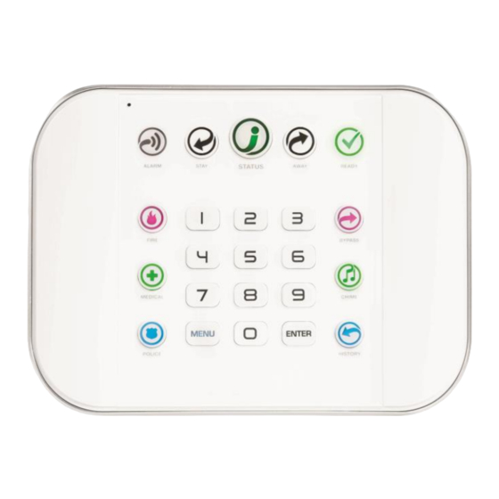
Page 13: Front Of Zerowire
Front of ZeroWire Color Description Color Description All sensors are ready and the System is in alarm. Enter your Green system can be armed in Away or PIN code then ENTER to turn off (steady) Stay mode. the alarm. Press the STATUS key ALARM for more info. -
Page 14: Back Of Zerowire
Back of ZeroWire Connections for the cellular radio module are located under the cover on the right. ZeroWire Reference Guide P/N 466-5227 • REVA • ISS 26AUG15 ©2015 United Technologies Corporation .. . -
Page 15: Hardware Installation
REFERENCE GUIDE MODEL ZW-6400 1 Hardware Installation What You Need ZeroWire Panel ZeroWire Accessories (Intrusion Detection Devices, Lifestyle Devices, lights locks etc.) A mobile or smart device, or computer for programming List of users and PIN codes you wish to add ... -
Page 16: Install The Battery
1.1 Install the Battery Remove battery cover Connect battery pack Replace battery cover with a small lead to connector on the and screw. screwdriver. left inside battery compartment. Connectors are keyed. 1.2 Connect Power Lead to panel Connect power lead from power supply to the back of the ZeroWire. The connector is keyed and only fits one way. -
Page 17: Connect Power
Hole location, shading: Align the ZeroWire with the top clips on the wall bracket, and then push the ZeroWire so it sits flat against the wall. Note: Ensure the screw on the underside of the ZeroWire is loosened; if not the ZeroWire may not fit flush against the wall. - Page 18 ZeroWire Reference Guide P/N 466-5227 • REVA • ISS 26AUG15 ©2015 United Technologies Corporation .. .
-
Page 19: Set Up Connections
REFERENCE GUIDE MODEL ZW-6400 2 Set Up Connections 2.1 Select a Permanent Connection Mode Select a method to connect your ZeroWire to a network so it can report events via UltraSync, and allow you to configure settings using the built-in Web Server or UltraSync app. Recommended installations use IP as primary reporting with cellular backup. -
Page 20: Option 1 - Ethernet Setup
2.2 Option 1 - Ethernet Setup To internet Router Connect power to your ZeroWire. If this ZeroWire was previously connected via Wi Fi, switch connection to Ethernet: Connect an Ethernet cable to the rear of the ZeroWire and wait 10 sec for the local router to assign the ZeroWire an IP address. -
Page 21: Check Ethernet Connection To Ultrasync
2.3 Check Ethernet Connection to UltraSync Login to the ZeroWire Web Server from your mobile device or computer using the IP address announced. Press Settings. Select Connection Status in the drop down menu. Check that a. LAN Status should display Connected. b. -
Page 22: Option 2 - Wi Fi Setup
2.4 Option 2 - Wi Fi Setup Turn on Wi Fi Discovery Mode – this provides direct access to the ZeroWire from a mobile device such as a smart phone, tablet, or laptop: Enable Wi Fi on your mobile device On your mobile device, browse for available Wi Fi networks and select the ZeroWire_xxxx network to connect to it. -
Page 23: Set Up A Web Access Passcode For Ultrasync
Set Up a Web Access Passcode for UltraSync For security, the UltraSync app is disabled by default. Follow these steps to enable it: Press then for the page. Select Network from the drop down menu. Enter a Web Access Passcode: Press Save. - Page 24 Press the Wi Fi network name you wish ZeroWire to connect to. Enter Wi Fi passcode then press OK. “Network Successfully selected” will appear as shown below. Your mobile device will be disconnected from the ZeroWire. On your mobile device, connect to the same Wi Fi network found by the scan. On the ZeroWire press Menu –...
-
Page 25: Troubleshooting Wi Fi Setup
Troubleshooting Wi Fi Setup 1. Cannot get an IP address Cause Solution Close the web browser on your device, and restart your Connection does not work wireless router, and start again from step 1. The wireless/router may not be configured for automatic DHCP or certain security settings may be Check your router settings and try again. -
Page 26: Check Wi Fi Connection To Ultrasync
2.5 Check Wi Fi Connection to UltraSync Login to the ZeroWire Web Server from your mobile device or computer using the IP address announced. Press Settings. Select or press Connection Status in the drop down menu. Check that a. LAN Status should display Connected. b. -
Page 27: The Ultrasync App
REFERENCE GUIDE MODEL ZW-6400 3 The UltraSync App 3.1 Install UltraSync App UltraSync is an app that allows you to control your ZeroWire from an Apple® iPhone/iPad, or Google Android device. First set up the ZeroWire Web Server then download this app. Carrier charges may apply and an Apple iTunes or Google account is required. -
Page 28: Using The App
Press Done button to save the details, then Sites to go back. Press the name of the Site, the app will now connect you to ZeroWire. 3.2 Using the App The first screen that will appear once you connect is Arm/Disarm. This will display the status of your system and allows you to arm or disarm areas by pressing Away, Stay, or Off. - Page 29 Press to view any cameras connected to the system. This is a live view of the camera. Press to view the last recorded clip by that camera. clip progress You can also access video clips linked to History events. Press from the History screen.
- Page 30 If you have ZWave devices installed, press Rooms to view and control them. Master users will have access to the full Users menu for creating and managing users. See Section 6, Users and Permissions for definitions of user levels and permissions. When you login with the Installer account you will also have access to additional menus for setting up and programming the ZeroWire.
-
Page 31: Recommended Items To Change
Installer menu, Settings Installer menu, Advanced 3.3 Recommended Items to Change INSTALLER CODE This is the dealer’s access key to most features. Always change this to prevent accidental modifications by end-users and unauthorized access to the security system. INSTALLER PHONE NUMBER This is announced to the user when certain status conditions occur. - Page 32 Enable remote access for UltraSync app by changing Web Access Passcode. The default Web Access Passcode of 00000000 prevents remote access. To change it, login to ZeroWire Web Server and go to Settings – Network: Enable remote access for DLX900 by changing the Download Access Code.
-
Page 33: Troubleshooting Ultrasync Setup
3.4 Troubleshooting UltraSync Setup 1. UltraSync Site Creation fails Cause Solution Check the serial number, web access passcode, user name and PIN codes match those in the ZeroWire. Settings are entered incorrectly Web Access Passcode must not be 00000000. User Name must be entered with a space between the first and last name and with correct capitalization. - Page 34 ZeroWire Reference Guide P/N 466-5227 • REVA • ISS 26AUG15 ©2015 United Technologies Corporation .. .
-
Page 35: System Settings
REFERENCE GUIDE MODEL ZW-6400 4 System Settings These instructions describe how to program all of the devices, schedules and areas used by the system. 4.1 Learn Sensors into ZeroWire Connect to the ZeroWire Web Server (either via Wi Fi Discovery Mode, Wi Fi, Ethernet LAN, or the UltraSync app). - Page 36 At this point you can type the name of the sensor and define its profile, by determining the sensor type (Entry, 24 hour, fire, key switch, etc.) and the sensor options (bypass, force arm, Cross Zone, stay mode, etc.). You can also assign it a specific area. Each of these has a drop down menu to make selections.
- Page 37 Sensor Type Sensor Options Sensor Area Group Give a name and definition to the sensor and press Learn. A notification box will appear below the learn button. Activate the sensor. Consult the sensor manual for instructions; generally this is performed by opening the case and manipulating the tamper activator. This will send a tamper signal to ZeroWire.
- Page 38 The screen below shows a sensor learned in. Name: Front Door Type: Entry Exit Delay 1 Option: Bypass Area Group: Area 1 Serial Number: A8E551 Note that the sensor Serial Number box has been populated after learning in the sensor. Explanations of the sensor configurations appear on the next page.
- Page 39 Default Option Function Select Sensor to Configure 1 Sensor Choose among 60 sensors. Sensor Name Blank Custom 32 character name Sensor types determine the sensor attributes such as entry/exit, instant, etc. Sensor Type 3 Entry Exit Delay 1 Additionally sensor types determine the siren attributes.
-
Page 40: Learn In A Keyfob
4.2 Learn in a Keyfob From the UltraSync app press the button then You are on the page. Select the drop down menu under Sensors to see the list of programmable items. Select Keyfobs. With the keyfobs screen selected you can choose the keyfob number to configure and select the user number to link to the keyfob. - Page 41 Give the keyfob a number, select the user and press Learn. A notification box will appear below the learn button. Activate the keyfob. Consult the keyfob manual for instructions; generally this is performed by simultaneously pressing the lock and unlock buttons. This will send a tamper signal to ZeroWire.
- Page 42 Option Default Function Select Keyfob to Configure 65 Keyfob This is the starting Sensor number for Keyfobs. If "Use FOB Number as Standard User” is used, when there is an activation on that Fob the Central Use FOB Station report will come in with that sensor number. User Number as If there is a user assigned to the fob that user...
-
Page 43: Programming Areas
4.3 Programming Areas From the UltraSync app press the button then You are on the page. Select Areas from the drop down menu. With the Areas screen selected you can choose an Area number to configure, give the area a name, and define attributes for that area. The ZeroWire can support a total of 4 areas;... - Page 44 Option Default Function Use the drop down menu to select which of the Select Area to Configure Area 1 4 areas to program. Each area can be configured with a custom 32 character name. The area name is displayed Area Name Blank wherever an area is referenced on the ZeroWire system.
- Page 45 This account number is ONLY used when sending an email. This should be the same as the Central Station account number, Area Account however if it is not this will not affect the Central Station reporting This determines which channel will be used to report area events to the Central Station.
-
Page 46: Programming The System
4.4 Programming the System Press then for the page. Select System from the drop down menu. When the System screen is selected you can program several system wide settings, including the system clock and timers, as well as sensor options and reporting. Explanations of the System configurations appear on the following pages. - Page 47 Option Default Function Once it is connected to UltraSync the Date and time are Date automatically synced. Once it is connected to UltraSync the Date and time are Time (hh:mm:ss) automatically synced. Starting with EST is UTC-5, CST is UTC-6, MT is UTC-6, Hours Offset UTC 5 ET PST is UTC-7.
- Page 48 Option Default Function This applies only to wireless sensors programmed as fire type. Sensors send a reduced packet count supervisory signal every 60 minutes (check your sensor manual for most up to date details). If no supervisory Fire Supervise Time signal is received by the panel within the time specified (120-65535) 14400...
- Page 49 When you are finished programming the System settings, remember to save your changes. ZeroWire Reference Guide P/N 466-5227 • REVA • ISS 26AUG15 ©2015 United Technologies Corporation .. .
-
Page 50: Programming Channels
4.5 Programming Channels Press then for the page. Select Channels from the drop down menu. With the Channels screen selected you can program a communication path for events to be sent from the ZeroWire panel to a selected destination. The ZeroWire can support a total of 16 channels; each channel is identified by a unique channel number, which cannot be altered, and remains as the key reference for each channel. - Page 51 Option Default Function Select Channel to Configure 1 Central Station Primary Custom names of the selected channel Channel Name Central Station Primary can be created here. This is the Account Number that will be reported with the event in email reports. Account Number Blank When UltraSync format is selected, this...
-
Page 52: Programming The Network
4.6 Programming the Network Press then for the page. Select Network from the drop down menu. Enter your network settings on this page. Explanations of the Network Configuration Menu appear on the following pages. Remember to save your changes when you are finished programming the Network settings. ZeroWire Reference Guide P/N 466-5227 •... - Page 53 Option Default Function LAN Configuration A text label assigned to the ZeroWire communicator so you do not have to remember the IP Address. IP Host Name Note: This only works on local LAN and with Microsoft Windows PC, or an Apple device with the .local extension.
- Page 54 Option Default Function This is an automatic feature of ZeroWire. It is recommended you leave this setting on. Enable this option to allow ZeroWire to send email reports via the UltraSync servers. This is independent of the Web Access Passcode which when set to 00000000 will prevent the UltraSync app from connecting.
-
Page 55: Programming Scenes
4.7 Programming Scenes Press then for the page. Select Scenes from the drop down menu. With the Scenes screen selected you can create scenes on schedules and determine which event types and device triggers will activate them. Each scene can trigger up to 16 consecutive scene actions when certain conditions are met. This can save users time by automatically running multiple actions. - Page 56 1. Enter a scene name. 2. Select the Activate Schedule drop down menu to restrict when the scene will be enabled 3. Select the event that will trigger recording a video clip using the Activate Event Type drop down menu. 4.
- Page 57 Option Default Function The ZeroWire can support a total of 16 Scenes. Each Scene is identified by a unique number, which Select Scene to Configure cannot be altered, and remains the key reference for each Scene. Each Scene can be configured with a custom 32 Scene Name character name.
-
Page 58: Programming Schedules
4.8 Programming Schedules Press then for the page. Select Schedules from the drop down menu. With the Schedules screen selected you can create up to 16 schedules, each having four time and day periods. Explanations of the Schedules Configuration menus appear on the following pages. Also reference Schedules Programming (Advanced), section 5.6. - Page 59 Option Default Function The ZeroWire can support a total of 96 schedules. Each schedule is identified by a Select Schedule to Configure 1 Schedule 1 unique schedule number, which cannot be altered, and remains as the key reference for each schedule. Each schedule can be configured with a custom 32 character name.
-
Page 60: Programming Holidays
4.9 Programming Holidays Press then for the page. Select Holidays from the drop down menu. With the Holidays screen selected you can create up to four sets of holiday dates for the Zerowire. Set the number, name and date range for each holiday. Remember to save your changes when you are finished programming the Holidays settings. - Page 61 Example Office Worker User Permission 1 – All Areas Permission Schedule 1 – 8am- 8pm M-F, Holidays 1 (checked) An office is not staffed during a public holiday and you want to prevent access to the building from staff on this date. First program the holiday dates in this section under “Holiday 1”, then go to Schedules and check “Holidays 1”, then assign that schedule to the User.
-
Page 62: Programming Zwave Devices
4.10 Programming Zwave Devices Press then for the page. See the Zwave Configuration Menu later in this section. Also reference Devices Programming (Advanced), section 5.9. Zwave Room Names Select Zwave Room Names from the drop down menu. From the drop down menu under Zwave Room Editor select a room to edit the name. For this example we will change the name of Room 1 to Living Room. -
Page 63: Zwave Device Association
3. Press Rooms. 4. Check that you can see the device you just added. Press a button such as ON or OFF to verify you can control the device. Zwave Device Association Select Zwave Device Association from the drop down menu. ZeroWire Reference Guide P/N 466-5227 •... -
Page 64: Zwave Maintenance
Zwave Maintenance Select Zwave Maintenance from the drop down menu. Option Default Function Zwave Room Editor Drop down to select room to edit Room Selection Room Names Edit Room Name Room 1 Room Naming Drop down to select the room Device Room Location location Device... -
Page 65: Wi Fi Setup
4.11 Wi Fi Setup Turn on Wi Fi Discovery Mode – this provides direct access to the ZeroWire from a mobile device such as a smart phone, tablet, or laptop: Enable Wi Fi on your mobile device On your mobile device, browse for available Wi Fi networks and select the ZeroWire_xxxx network to connect to it. -
Page 66: Set Up A Web Access Passcode For Ultrasync
Set Up a Web Access Passcode for UltraSync For security, the UltraSync app is disabled by default. Follow these steps to enable it: Press then for the page. Select Network from the drop down menu. Enter a Web Access Passcode: Press Save. - Page 67 Press the Wi Fi network name you wish ZeroWire to connect to. Enter Wi Fi passcode then press OK. “Network Successfully selected” will appear as shown below. Your mobile device will be disconnected from the ZeroWire. On your mobile device, connect to the same Wi Fi network found by the scan. On the ZeroWire press Menu –...
-
Page 68: Troubleshooting Wi Fi Setup
To internet Wireless Router Troubleshooting Wi Fi Setup 1. Cannot get an IP address Cause Solution Close the web browser on your device, and restart your Connection does not work wireless router, and start again from step 1. The wireless/router may not be configured for automatic DHCP or certain security settings may be Check your router settings and try again. -
Page 69: Check Wi Fi Connection To Ultrasync
4.12 Check Wi Fi Connection to UltraSync Login to the ZeroWire Web Server from your mobile device or computer using the IP address announced. Press Settings. Select or press Connection Status in the drop down menu. Check that g. LAN Status should display Connected. h. -
Page 70: Programming Cameras
4.13 Programming Cameras Press then for the page. Also reference Camera Setup Instructions in section 8. Select Cameras from the drop down menu. ZeroWire supports selected IP cameras. Contact your supplier for the correct model(s). Install camera according to the manual supplied with the camera. Add a Camera Method 1 –... -
Page 71: Check Connection Status
Option Default Function Finds UltraSync cameras added to the Scan For New Cameras same IP network as ZeroWire Camera Configuration Drop down for all the cameras Camera Name IP Address MAC address 4.14 Check Connection Status Press then for the page. - Page 72 4.15 Check Details Press then for the page. Select Details from the drop down menu. Detail Names Detail Function Control Name Device UID (Serial) Serial number of the ZeroWire Ethernet MAC Address WI FI MAC Address Control Model Firmware Version Hardware Version Bootloader Voce Version...
-
Page 73: Advanced Installation Using Web Server
REFERENCE GUIDE MODEL ZW-6400 5 Advanced Installation Using Web Server Advanced settings are only accessible via the ZeroWire Web Server, UltraSync app, or DLX900. From the UltraSync app press the button then You are on the page. 5.1 System Programming (Advanced) Select System from the menu. - Page 74 S y s t e m S u b m e n u s 1 System Clock 2 Clock Date and Time The ZeroWire system clock can manage day, time, time sensor, and day light saving time settings to ensure ongoing accurate time. 3 Time Sensor - Hours Offset / Minutes 4 Daylight Saving Time Offset...
- Page 75 1General Options Option Default Function If enabled, the two (2) hardwired sensor inputs will be doubled to support four (4) sensors. The terminals for Sensor 1 will Panel Sensor represent sensors 1 and 3, and the terminals for sensor 2 will Doubling represent sensor 2 and 4.
- Page 76 1 System Timers Option Default Function Siren Time (0-99) The siren time sets the time in minutes that the siren output is Minutes active. The strobe time is the duration in hours that output Strobe Time (0-99) programmed to follow the strobe time will activate. The valid time selection in this segment is 0 to 99 hours, where ‘0’...
- Page 77 Option Default Function The holdup delay is the duration in second that a holdup delay sensor type will wait before it activates. If additional holdup Holdup Delay activations occur during the holdup delay period then the (0-999) Seconds holdup delay will immediately expire and set the holdup alarm. If a holdup delay sensor type is de-activated during the holdup delay period then the holdup alarm will reset and not activate.
- Page 78 1 Siren Options 1. Siren Once Per Sensor If enabled, the ZeroWire will only set the siren once per sensor in a given arm cycle and will not set the siren again even if that siren time expires and that sensor reactivates. Every sensor will have one siren activation attempt before that sensor cannot reactivate the siren.
- Page 79 1 Service and Test Options 2 Email Intervals If enabled, the ZeroWire will report a system status email via one or more email channels. The number Service and Test Options Submenu entered for Status Email Interval is the number of days between status reports.
- Page 80 2 LAN Status 1 Status 3 LAN Media 4 Cell State 5 UltraConnect Status (UltraSync) 6 UltraConnect Media (UltraSync) 7 Cell Service 8 Signal Strength 9 Operator ID 10 Radio Technology ZeroWire Reference Guide P/N 466-5227 • REVA • ISS 26AUG15 ©2015 United Technologies Corporation ..
- Page 81 1 Counts Swinger Shutdown is a false alarm prevention feature that counts the number of alarms caused by a specific sensor. After a certain number of alarms caused by the same sensor within the same arming period, the controller will then shutdown that sensor for the remainder of that arming period. The sensor will be reinstated when the system is disarmed or rearmed to any security mode.
-
Page 82: Sensor Programming (Advanced)
5.2 Sensor Programming (Advanced) Press then for the page. Select Sensors from the menu. A sensor (sometime referred to as a sensor or input) on the ZeroWire is a single physical hardwired connection or a non-physical wireless connection. Additionally sensors on the ZeroWire can be used as logic inputs within actions and / or be configured as one of many sensor types. - Page 83 4 Sensor Type One of 32 configurable sensor types may be allocated to any sensor’s sensor type. Each sensor type can behave independently between an arm and disarmed state. Sensor types determine the sensor attributes, siren attributes, and sensor attribute options. Here is an example of a preset sensor type: Sensor Type –...
- Page 84 5 Sensor Options 6 Area Group (1-16) One of 16 configurable area groups can be allocated to any sensor’s area group. Area groups are a list of ZeroWire areas. When an area group is allocated to a sensor, that sensor will then belong to all the areas in the area group.
- Page 85 8 User Number The sensor user number feature is used whenever the sensor type is set to “keyswitch”. Instructions for users configuration are in Section 6 – Users and Permissions. One of 40 configurable users can be allocated to any sensor’s user number. ZeroWire sensor profile user number is a powerful feature that is used to apply the selected user’s attributes to a keyswitch operation.
-
Page 86: Areas Programming (Advanced)
5.3 Areas Programming (Advanced) Press then for the page. Select Areas from the menu. A r e a s S u b m e n u s 1 Area Number 2 Area Name The ZeroWire can support a total of 4 areas. Each Each area can be configured with a custom 32 area is identified by a unique area number, which character name. - Page 87 3 Area Entry-Exit times ZeroWire uses the area entry and exit timers to delay the activation of an alarm event when entry/exit sensor types are activated. When an area is turned on, it will start an Exit 1 timer. While an Exit 1 timer is running – Entry 1, Entry 2, and Handover sensor types will not create an alarm.
- Page 88 4 Area Options 1. Arm/Disarm Reports If enabled, this area will send open and close reports via one or more appropriately configured channels. 2. Quick Away If enabled, this area can be armed in away mode via a single away mode key press. When an area is armed via quick away mode, the closing user number is the default user of 999.
- Page 89 6. Siren Chirp Stay If enabled, the ZeroWire will activate the built-in siren briefly each time this area is set in stay mode with a key-switch sensor or wireless keyfob. 7. Force Arm With Bypass If enabled, the area can be armed even if sensors are not ready. Any sensors that are not ready will automatically be bypassed, log the bypass, and optionally report the bypass.
-
Page 90: Notes On Force Arming, Bypass, And Auto-Bypass
Notes on Force Arming, Bypass, and Auto-Bypass Normally to arm an area it must first be “Ready to Arm”. This means all sensors in that area must be sealed. For example, if the front door is open, then a user would need to close it first and ensure there is no movement in the reception area. - Page 91 Sensors If Auto-Bypass Sensors enabled then Auto-bypassed sensor is restored Ready = Ready = auto-bypass all Area Area Not not ready Bypassed sensors remain bypassed Ready Ready sensors Else Alarm Force Arm Sensor restores Area Type Exit Area Armed Delay Time If armed, and entry/exit sensor tripped, Arm in Away mode...
- Page 92 5 Area Timers Auto Arm Warning If the area type is Standard and Arm / Disarm is configured, this timer delays arming by the minutes entered. If the area type is Timed Disarm, Man Down, or Guard Tour, this setting is a warning time given to a user once the user’s Disarm Time, Man Down Time, or Guard Tour Time has expired.
- Page 93 The following conditions must be true before a timed area disarm function will occur. The area type must be set to Timed Disarm. The area type schedule must be active. The users active profile’s permission must have; This area set in the permission’s timed disarm area group. The permission must be in schedule.
- Page 94 Early Open/Late Close If the area type is Early Open & Late Close, the Area Type Delay sets the period after the start (opening) and the end (closing) of the area type schedule that the area must be either disarmed or armed. For example, if the area type schedule is set between 8:00 AM (opening time) and 5:00 PM (closing time) and the Area Type Delay is set to 15 minutes;...
- Page 95 Example Area Type – Early Open & Late Close Area Type Schedule – 8:00 to 17:00 Area Type Delay – 15 min User Permissions – Options – Open/close report, Early open report, Late close report Area Options – Arm-Disarm Reports Send Fail to Send Early Send Open...
- Page 96 8 Area Event Reporting/Account 9 Area Event Reporting/Channels If set, the area account code is a system unique The channel group determines which communicator 4 to 10 digit code (format dependent) used to channel(s) area events will be reported to. If the bit associate area related alarm reporting events to corresponding to one of the 16 reporting channels is this area.
-
Page 97: Channels Programming (Advanced)
5.4 Channels Programming (Advanced) Press then for the page. Select Channels from menu. The ZeroWire can support a total of 16 channels; each channel is a communication path for events to be sent from the ZeroWire panel to a selected destination. Default configuration reserves Channels 1 –... - Page 98 4 Format 5 Device Number This is the communication format for the selected channel. Select from: Use as Backup UltraSync Email 6 Destination Phone/Email 7 Next Channel 1-16 If the channel selected is unable to deliver the The phone number or email address of the selected event to the selected destination, ZeroWire will try destination.
-
Page 99: Configure Email Reporting
Configure Email Reporting 1. Login to ZeroWire Web Server or UltraSync app. Use an Installer or Master user account. 2. Press Settings. 3. Select Channels in the drop down menu. 4. Press Select Channel to Configure where the Format is already set to Email. 5. -
Page 100: Communicator Programming (Advanced)
5.5 Communicator Programming (Advanced) Press then for the page. Select Communicator from menu. The ZeroWire Communicator is a core component of the ZeroWire System used in conjunction with the Channels feature to report events to a monitoring company or third party. In this menu you can configure the settings for various methods of reporting. - Page 101 1. First Disarm Last Arm If enabled, the ZeroWire will only send a closing report when the last area is armed. Note: The last area to arm must have open/close reports enabled. The ZeroWire will only send an opening report when the first area is disarmed. This feature is used in place of Individual area Open and close.
- Page 102 4 IP Configuration 5-6 IP Config Detail 7-10 IP Config Detail Host Name This is a text label assigned to the ZeroWire communicator so you do not have to remember the IP Address. Gateway Note: This only works on local LAN and with If required, the IP address of the router which is Microsoft Windows PC, or an Apple device with needed when remote IP communications are used .
- Page 103 11 Ports 12-14 IP Config Detail ports that computer needs communicate with the ZeroWire system. Defaults: HTTP Port = 80 HTTPS Port = 443 Download Port = 41796 15 Time Server Enter the URL or IP address of a time server to allow the ZeroWire to automatically update and synchronise its clock without user intervention.
- Page 104 4. Enable Ping Allow the ZeroWire panel to respond to the PING command. 5. Enable Clock Updates Allow the ZeroWire internal clock to synchronise with the internet time server specified . 6. Enable Web Program Enabling this option will cause ZeroWire Web Server and UltraSync app to always display Installer menus regardless of if the panel is in program mode or not.
- Page 105 17 Radio Configuration 18 GPRS Username/Password 19 APN 20 Radio Options Access Point Name (APN) for the settings to set up a connection to the gateway between the cellular network and the public Internet. 22 Remote Access 21 SIM Preset 23 Panel Device Number 24 Download Access Code A variable length code for the computer user.
- Page 106 26 Download Options 1. Call Back Before Download If a download is requested the ZeroWire will hang up and make a call to the Call Back Number. This is to increase the security of remote access. 2. Lock local Programming Prevent changes to the ZeroWire system via a keypad, all changes MUST be made using the remote access software.
- Page 107 In the diagram below, ZeroWire will try Channel 1 3 times, switch to Channel 2 and try 2 times, then go back to Channel 1. This sequence is repeated 2 times in total. In total there will be 10 attempts. Channel 1 Channel 2 3 tries...
-
Page 108: Schedules Programming (Advanced)
5.6 Schedules Programming (Advanced) Press then for the page. Select Schedules from the menu. S c h e d u l e s S u b m e n u s 1 Schedule Number 2 Schedule Name Each schedule can be configured with a custom 32 character name. - Page 109 Follow Action Permissions (users and devices) Area Types Action Schedule controls controls Sensor Profiles Arm-Disarm Scenes 4 Times and Days ZeroWire handles schedules that span midnight automatically. For example, if a schedule is to cover Fri 8:00pm to Sat 6:00am, only check Friday and ZeroWire will automatically manage the time after midnight.
-
Page 110: Actions Programming (Advanced)
5.7 Actions Programming (Advanced) The ZeroWire features powerful automation control which can interact with different parts of the system. It can perform functions based on the status of one or more system conditions. Each action has an on and off state. The state is controlled by up to 4 conditions called Action Events, each of which can have a range of items: A c t i o n E v e n t S e q u e n c e Action... - Page 111 A c t i o n s S u b m e n u s 1 Action Number 2 Action Name Each Action can be configured with a custom 32 character name. The name is displayed wherever an Action is referenced on the ZeroWire system. 3 Function ...
- Page 112 4 Duration: Minutes 5 Duration: Seconds Where the Function requires duration, this Where the Function requires duration, this determines, in minutes, how long the action should determines, in seconds, how long the action stay on should stay on 6 Event(s) 1-4 and Results 7 Event Attributes 8 Event Category 9 Event Type...
- Page 113 10 Event Start Range 11 Event End Range Select the starting number of the event that you want Select the ending number of the event that you the Action to monitor. This is related to a number want the Action to monitor. This is related to a range.
- Page 114 14 Result Category 13 Result The category of the Action Result to perform See the Action Results Category and Action The ZeroWire can also perform an additional Results Event Types table in section A.11 function once the Action Event conditions are for reference.
-
Page 115: Arm-Disarm Programming (Advanced)
5.8 Arm-Disarm Programming (Advanced) Press then for the page. Select Arm-Disarm from the menu. A r m - D i s a r m S u b m e n u s 1 Number (1-8) 2 Name The ZeroWire can support a total of 96 Arm-Disarm. Each group can be configured with a custom 32 Each Arm-Disarm is identified by a unique number, character name. - Page 116 The ZeroWire Communicator has a powerful automation feature which simulates a user performing arming and disarming of the system according to a specified schedule. When a Schedule becomes valid (inside valid time sensor) the ZeroWire will disarm all Areas that are in the User’s - Active Profile - Disarm Area Group.
-
Page 117: Devices Programming (Advanced)
5.9 Devices Programming (Advanced) Press then for the page. Select Devices from the menu. This menu allows you to program devices connected to the ZeroWire system. D e v i c e s S u b m e n u s 1 System Devices Control 2 System Devices Control Device Number... - Page 118 5 Control Info 6 Control Output 1 The ZeroWire has 2 on-board outputs which can be programmed to follow actions. Version information about the ZeroWire including firmware, voice, web, and MAC address. 7 Control Output 1 Output Name 8 Control Output 1 Action Assignment Each output can be configured with a custom 32 character name.
- Page 119 11 Interlogix Transmitters 12 Serial Number Serial number of the Interlogix Device Number of the Interlogix Transmitter 13 User 14 Transmitter Options By default all keyfobs are reported as user 999. To enable individual keyfob reporting, assign a user number here.
- Page 120 15 Scene 16 Zwave Devices On a four-button keyfob, this allows the user to activate a scene when the fourth button is pressed. 17 Zwave Devices Name 18 Zwave Devices Basic Type 19 Zwave Devices Generic Type 20 Zwave Devices Specific Type 19 Zwave Devices Generic Type 20 Zwave Devices Specific Type ZeroWire Reference Guide...
-
Page 121: Permissions Programming (Advanced)
5.10 Permissions Programming (Advanced) Press then for the page. Select Permissions from the menu. Permissions control what a user or device has access to on the ZeroWire system and what they can do. P e r m i s s i o n s S u b m e n u s 1 Permission Number 2 Permission Name Each set of Permissions is identified by a unique... - Page 122 3 Control Groups 1. Menu Group 6. Man Down Area Group This controls what menus the user or device can This controls which areas will have man down access monitoring. 2. Arm Area Group 7. Guard Tour Area Group This controls which areas can be armed. This controls which areas are a part of the guard tour.
- Page 123 4 Permission Options 1. Remote Access - Enables and disable remote Arm Action Trigger - When enabled, this users will trigger the Action trigger event “User Arm web access to the permission. If this is not Trigger” when arming A area, used in conjunction enabled, a user will not be able to access the web interface directly or via a smartphone app.
- Page 124 5 User Timer Options 1. Disarm Time 2. Man Down Time 3. Guard Tour Time These timers apply to a user when allocated this permission and: • the Area Type is set to Timed Disarm, Man Down, or Guard Tour, •...
-
Page 125: Area Groups Programming (Advanced)
5.11 Area Groups Programming (Advanced) Press then for the page. Select Area Groups from the menu. The ZeroWire can support a total of 16 Area Groups. Each Area Group is identified by a unique number, which cannot be altered, and remains as the key reference for each area. When assigned to a user, an Area Group controls what areas the user can see and control. -
Page 126: Menus Programming (Advanced)
5.12 Menus Programming (Advanced) Press then for the page. Select Menus from the menu. Menus are assigned to users and devices to control what menus can be accessed. A total of 64 Menus can be configured. M e n u s S u b m e n u s 1 Menu Number (1 –... -
Page 127: Holidays Programming (Advanced)
5.13 Holidays Programming (Advanced) Press then for the page. Select Holidays from the menu. Also reference Section 4.9 Programming Holidays H o l i d a y s S u b m e n u s 1 Holiday Number (1 – 4) 2 Holiday Name 3 Holiday Date Range ZeroWire Reference Guide... -
Page 128: Sensor Types Programming (Advanced)
5.14 Sensor Types Programming (Advanced) Press then for the page. Select Sensor Types from the menu. Sensors can be programmed to be one of 32 different sensor configurations (sensor type profiles). Sensors are fully configurable in the ZeroWire panel. These features are considered advanced programming and should only be changed with a thorough understanding of the operation of each bit. - Page 129 3 Sensor Type Profile / Armed Sensor Attribute This is how the sensor will behave when the area it is in is armed. • Disabled – sensor is disabled. • Entry 1 – sensor will follow area entry/exit timer 1. •...
- Page 130 Sensor Attribute Options (Armed or Disarmed) • Code Pad Sounder – If enabled, the panel will announce alarm, tamper, or trouble conditions. Default is on. • Report Delay – if enabled, the ZeroWire will delay reporting sensor activations until the next scheduled report.
-
Page 131: Sensor Types Table
Sensor Types Table Armed Day Sensor Instant Yelping 24 Hour Audible Instant Yelping Entry Exit Delay 1 Entry 1 Yelping Entry Exit Delay 2 Entry 2 Yelping Follower Handover Yelping Instant Instant Yelping 24 Hour Silent Instant Yelping Fire Alarm Fire Steady Entry Exit Delay 1 Auto-... -
Page 132: Sensor Options Programming (Advanced)
5.15 Sensor Options Programming (Advanced) then for the page. Press Select Sensor Options from the menu. Sensors are fully configurable in the ZeroWire panel. These features are considered advanced programming and should only be changed with a thorough understanding of the operation of each bit. - Page 133 If this feature is off then all the areas must be armed before the sensor will become active. If sensor is type 10 sensor (Interlogix Door/Window sensor) then these two options apply: Disable Internal Reed Switch – check this box when using external contacts.
- Page 134 4 Sensor Reporting 5 Sensor Contact Options (Applies to the hardwire inputs, not wireless sensors.) • • Alarms Reporting – if enabled, this sensor will Normally Open no EOL – if enabled, the sensor report alarms. circuit is normally open. Default is off. •...
-
Page 135: Sensor Options Table
Sensor Options Table Bypass 134:BA Bypass Stay 130:BA Bypass – Forced Arm 134:BA Bypass – Cross Zone 134:BA Fire 110:FA Panic 120:PA Silent Panic 122:HA Normally Open no EOL 130:BA Normally Closed no EOL 130:BA Gas Detected 151:GA High Temp 158:KA Water Leakage 154:WA... -
Page 136: Event Lists Programming (Advanced)
5.16 Event Lists Programming (Advanced) then for the page. Press Select Event Lists from the menu. Event Lists are monitored by Channels to determine if they should be reported. Only events on a Channel’s associated Event List will be reported E v e n t L i s t s S u b m e n u s 1 Event List Number (1 –... -
Page 137: Channel Groups Programming (Advanced)
5.17 Channel Groups Programming (Advanced) then for the page. Press Select Channel Groups from the menu. The ZeroWire provides you powerful and flexible reporting capability through its Channel feature. They are fully configurable to suit your needs by allowing you to specify what events to report to single and multiple destinations, with multiple levels of back up paths. - Page 138 When a system event occurs, it is routed to the System Event Channel Group (Communicator\System Event Reporting\System Channels). The Channel Group will forward the event to each of the Channels it contains. If the event is on the Channel’s Event List, the Channel will attempt to send the event to the Channel’s destination.
-
Page 139: Customize Reporting Codes
Customize Reporting Codes The ZeroWire control panel has the ability to report Ademco Contact I.D. transmissions. Each report in Contact I.D. consists of an event code and the sensor I.D. generating the alarm. SIA Event Programmed Event Code Contact I.D. Code Description Code Use default code for... - Page 140 6. Press Save. 7. Press Settings and Sensors should appear. 8. Assign the customized Sensor Options to the Sensor. 9. Press Save. ZeroWire Reference Guide P/N 466-5227 • REVA • ISS 26AUG15 ©2015 United Technologies Corporation .. .
-
Page 141: Reporting Fixed Codes In Contact I.d
Reporting Fixed Codes in Contact I.D. The table below lists the CID event codes sent for the following reports (if enabled). The number in brackets following the event is the number that will be reported as the sensor number if extended Contact I.D. is enabled in the system options. Otherwise sensor ‘0’ will always be reported. -
Page 142: Scenes Programming (Advanced)
5.18 Scenes Programming (Advanced) then for the page. Press Select Scenes from the menu. S c e n e s S u b m e n u s 1 Scene Number (1 – 16) 2 Scene Name Each group can be configured with a custom 32 character name. - Page 143 5 Activate Sensor 6 Scene Action Number/Action Device Select which Area \ Sensor \ Schedule \ User \ Action \ Device will provide the trigger for the Scene. Each scene can trigger up to 16 scene actions when a certain condition is met. A scene can be triggered manually, through a schedule, or via a system event.
-
Page 144: Speech Tokens Programming (Advanced)
5.19 Speech Tokens Programming (Advanced) then for the page. Press Select Speech Tokens from the menu, and select a sensor token from the drop down menu. ZeroWire Reference Guide P/N 466-5227 • REVA • ISS 26AUG15 ©2015 United Technologies Corporation .. - Page 145 Select a voice name from the drop down menu. ZeroWire Reference Guide P/N 466-5227 • REVA • ISS 26AUG15 ©2015 United Technologies Corporation .. .
-
Page 146: Cameras Programming (Advanced)
5.20 Cameras Programming (Advanced) then for the page. Press Select Cameras from the menu. Add a Camera Method 2 – Manual Entry 1. Enter a name for the camera. 2. Enter the IP address and MAC address (Submenu 3,4 below). 3. -
Page 147: Removing A Camera
Removing a Camera 1. Select the camera you wish to remove. 2. Delete the IP address and MAC address (Submenu 3,4 above). 3. Press Save. 4. Your camera will no longer be accessible from ZeroWire. 5. You may also make your entries using the DLX900. ZeroWire Reference Guide P/N 466-5227 •... -
Page 148: Ultraconnect (Ultrasync) Programming (Advanced)
5.21 UltraConnect (UltraSync) Programming (Advanced) then for the page. Press Select UltraConnect from the menu. ZeroWire can establish a secure VPN connection to UltraSync Servers to allow simplified set up and configuration of email reporting and remote access features. The server addresses are pre-programmed and SHOULD NOT be modified unless you are instructed to by technical support staff. -
Page 149: Users And Permissions
REFERENCE GUIDE MODEL ZW-6400 6 Users and Permissions A user is a ZeroWire operator that is granted the authority to control and or configure the ZeroWire system. The Users menu is where you add, delete or modify one of the 40 ZeroWire users. - Page 150 User Menu: Enter a First and/or Last Name. Enter a unique PIN code between 4 and 8 digits. Select a User Type: Master users can arm and disarm areas. They can create, delete, or modify user codes. They can also change system settings. ...
-
Page 151: Users Submenus
6.2 Users Submenus The following submenus describe the features associated with the Users Menu. U s e r S u b m e n u s User First Name Each user can be configured with a custom 16 character first name. The user name descriptor may be displayed in the event log, keypad and when remotely connected to the ZeroWire via the management software. -
Page 152: Permissions
User Type User Type provides quick configuration of user permissions. The available user types are: 1. Standard – Standard users can only change their own PIN codes and cannot change the settings of the system. They can arm and disarm areas to which they have access. 2. - Page 153 Permission Schedule 1 ZeroWire permission schedules determine when to allocate user permissions to a user. User permissions are numbered from 1 to 4 where permission 1 is the highest priority and permission 4 is the lowest priority. If user permission 1 schedule is not valid then user permission 2, 3 and 4 are checked in sequence until a valid schedule can be applied.
- Page 154 Master Custom Standard Master Engineer Only Engineer User Change their own Custom PIN code Arm areas Custom based on permissions Disarm areas Limited Custom based on permissions Can create and modify Custom Standard users Program ZeroWire Custom installation settings Can create and modify Engineer users Area Group When a non-Custom User Type is selected, this setting determines what areas that user...
-
Page 155: Cellular Radio Setup
REFERENCE GUIDE MODEL ZW-6400 7 Cellular Radio Setup An optional 3G cellular radio modem provides a backup reporting path to the central monitoring station over a cellular network if the Ethernet/Wi Fi connection is not working. Primary Path – Wi Fi or Ethernet Secondary Path –... -
Page 156: Install Optional Cellular Radio
7.1 Install Optional Cellular Radio A mobile device can provide general guidance on mobile network coverage. Look at the signal strength on a mobile device to verify there are 4/5 to 5/5 bars of reception in the location where you will install the ZeroWire. If the signal strength is low, find another location which has stronger signal strength. -
Page 157: Connect Power
Insert the whole radio module in to the ZeroWire taking care not to crimp any cables. Replace the cover on the ZeroWire. 7.2 Connect Power Connect power lead from power supply to the back of the ZeroWire. The connector is keyed and only fits one way. -
Page 158: Install External Antenna - Optional
7.4 Install External Antenna – Optional Complete this section only if signal strength is between -121 to -89. Unplug power supply from receptacle and remove battery from ZeroWire. Disconnect the antenna cable from the radio module. Gently pull retaining clips outwards and remove the rear circuit board. This is the internal antenna which will no longer be needed. - Page 159 External Antenna Connector. Use ONLY with external antenna Connect an external antenna to the antenna connector on the rear of the ZeroWire. To obtain maximum signal strength the external antenna must be fully extended. Re-check signal strength following steps in section 7.3. Move the ZeroWire or the antenna to another location if the signal is still too low.
-
Page 160: Check Cellular Connection To Ultrasync
7.5 Check Cellular Connection to UltraSync Turn on Wi Fi Discovery Mode – this provides direct access to the ZeroWire from a mobile device such as a smart phone, tablet, or laptop: Enable Wi Fi on your mobile device On your mobile device, browse for available Wi Fi networks and select the ZeroWire_xxxx network to connect to it. - Page 161 Connected Valid service If it does not: Check cellular connection: a. Look at cell state, it should display Connected. b. Wait until cell state displays Connected, press Reload to refresh the status. c. Check signal strength – signal strength should be between -91 to -51. d.
- Page 162 ZeroWire Reference Guide P/N 466-5227 • REVA • ISS 26AUG15 ©2015 United Technologies Corporation .. .
-
Page 163: Camera Setup Instructions
REFERENCE GUIDE MODEL ZW-6400 8 Camera Setup Instructions 8.1 Quick Setup Note: If the light source where the camera is installed experiences rapid, wide variations in lighting, the camera may not operate as intended. To quickly put the camera into operation: 1. -
Page 164: Wi Fi Signal Strength
8.3 Wi Fi Signal Strength Wi Fi signal strength can be checked in the Network section of the TruVision Browser. Use the scale below to measure if actions are needed to improve performance. 85+ – Excellent: No additional actions needed and default video resolutions settings may be increased if desired. -
Page 165: Add Camera To Network Via Wi Fi For Ios Device
8.4 Add Camera to Network via Wi Fi for iOS Device 1. Power up the camera. (Boot up may take 1-2 minutes) 2. From your iOS device, go to Settings, then Wi Fi. 3. Find and select TVW-xxxxx. (Listed under Devices) 4. -
Page 166: Add Camera To Network Via Ethernet For Ios Device (Non Dhcp)
8.6 Add Camera to Network via Ethernet for iOS Device (non DHCP) 1. Power up the camera. (Boot up may take 1-2 minutes) 2. From your iOS device, go to Settings, then Wi Fi. 3. Find and select TVW-xxxxx. (Listed under Devices) 4. -
Page 167: Add Camera To Network Via Ethernet For Windows Pc (Non Dhcp)
8.7 Add Camera to Network via Ethernet for Windows PC (non DHCP) 1. Power up the camera. (Boot up may take 1-2 minutes) 2. From your Windows PC, Find and connect to TVW-xxxxx in Wi Fi network list. 3. Go to Network and Sharing Center. Control Panel >... -
Page 168: Add Camera To Ultrasync
8.9 Add Camera to UltraSync Ensure proper installation of camera hardware before proceeding to camera setup. Make sure camera and UltraSecure intrusion panel are on the same local area network. Applications were the Intrusion panels uses cellular only are not compatible with this camera. Note: For detailed information on how to setup the UltraSync app, add locations, and login as an Installer, reference the intrusion panel installation guide. -
Page 169: View Live Stream And Latest Clip
8.10 View Live Stream and Latest Clip Press tab on bottom of the screen. All available cameras will be shown. Press to view a live feed of a specific camera. Press to view the last recorded clip from a specific camera. 8.11 Program event triggered camera clips Cameras can be programmed to automatically record when selected events occur. - Page 170 Select Action Device (1) Alarm System. This enables another drop down menu for Action Type. Choose the Action Type “Trigger Camera Video Clip”, then the cameras you wish to record a video clip when the event is triggered. Press Save. Clips are recorded on the Micro SD card installed in the camera and are linked to events in History.
-
Page 171: View Event Triggered Clips In History
Password: 1234 3. Change settings as desired such as video quality, frame rate, pre and post recording times. 4. For detailed instructions on using TruVision Navigator, go to www.interlogix.com/video. ZeroWire Reference Guide P/N 466-5227 • REVA • ISS 26AUG15 ©2015 United Technologies Corporation... -
Page 172: Camera Troubleshooting
8.14 Camera Troubleshooting 1. Camera is not showing in list of Wi Fi networks. Cause Solution The camera takes up to 90 seconds to boot up. It will not show in Wi Fi Networks until this is complete. The camera has previously been setup and ad hoc Perform a factory reset to broadcast the camera again. -
Page 173: Installation Using Keypad
REFERENCE GUIDE MODEL ZW-6400 9 Installation Using Keypad 9.1 Basic Installation It is possible to quickly install and test sensors using only the ZeroWire keypad, the voice guide will walk you through each option that requires programming. Additional sensor settings can be accessed via the ZeroWire Web Server, UltraSync app, or DLX900. -
Page 174: Configure Sensor Names (Optional)
9.3 Configure Sensor Names (optional) All sensors can be named; see the Voice Library table for reference. This makes it easier to identify the correct sensor in the event of a condition. You may enter up to eight words to achieve your desired description. Example: Configure sensor 1 name as “Dining Room Sensor”. - Page 175 Voice Library These words can be used to customize your sensor names. zero closet kitchen training computer lounge cool laundry upstairs three curtain lift user four data light utility five living volt detector location veranda seven dining master wall eight door medicine warehouse...
-
Page 176: Record Sensor Names (Optional)
9.4 Record Sensor Names (optional) You can also record the names of the first 64 sensors using your voice. Example: Record user name for sensor 1. 9.5 Test Sensor Signal Strength It is highly recommended you check the signal strength of each sensor once installed. Test the signal strength: If signal is low, then move sensor to another location. -
Page 177: Remove A Sensor
9.6 Remove a Sensor Example: Remove sensor 8. 9.7 Change the User Type (optional) The user type determines what that user can do: Master users can arm and disarm areas. They can create, delete, or modify user codes. They can also change system settings. Standard users can arm and disarm areas. -
Page 178: Record User Names (Optional)
Example: Change user 6 to a master user to allow them to add/remove users. 9.9 Record User Names (optional) You can also record the names of the first 40 users using your voice. Example: Record user name 1. 9.10 Remove a User Example: Remove user 4 from your system. -
Page 179: Add A Keyfob
9.11 Add a Keyfob Example: Add a new keyfob and assign it as user 65 9.12 Remove a Keyfob Example: Remove keyfob 65. Personalize Your ZeroWire 9.13 Volume Level Example: Set volume level to 6. ZeroWire Reference Guide P/N 466-5227 • REVA • ISS 26AUG15 ©2015 United Technologies Corporation .. -
Page 180: Voice Annunciation
9.14 Voice Annunciation Example: Turn on/off the voice when arming and disarming. 9.15 Full Menu Annunciation Turning this feature On, gives full descriptions to all the options within the main menu. Turning this feature Off shortens the descriptions. 9.16 Backlight Level Set Run Mode or Idle Mode brightness. -
Page 181: Change Time And Date
9.17 Change Time and Date Time and date are normally automatically updated with an internet time server. Example: Setting the time as 9.30AM, and the date as 19.6.2016. 9.18 Adjust Area Entry or Exit Times Example: Setting the entry time as 90 seconds. ZeroWire Reference Guide P/N 466-5227 •... -
Page 182: Reset Installer Account
9.19 Reset Installer Account Lost your Installer PIN code? Follow these steps to reset it: 1. Unplug the power supply and remove the backup battery. 2. Use a small screwdriver to hold down the reset button before you turn on power. 3. -
Page 183: Wall Tamper Option
9.22 Wall Tamper Option 1. CAUTION: Wall tamper is an optional security feature that is disabled by default. When enabled, the siren will make a very loud alarm sound when power is connected. Press 9-7-1-3 Enter to turn the siren off. If this does not work, reset the Installer account: a. - Page 184 To disable the inputs: Set System Menu -> General Options -> Disable Hardwired Sensors = ON To enable 2 inputs: Set System Menu -> General Options -> Disable Hardwire sensors = OFF Set System Menu -> General Options -> Panel Sensor Doubling = OFF ...
-
Page 185: Connecting Outputs
9.24 Connecting Outputs ZeroWire has two general purpose outputs located on the rear of the unit. See illustration in section 9.23, Connecting Inputs. These can be connected to up to 2 devices. Use the supplied header cable. Outputs are controlled by Actions in the ZeroWire. When an output is configured with an action, the output will monitor the status of the action: ... - Page 186 ZeroWire Reference Guide P/N 466-5227 • REVA • ISS 26AUG15 ©2015 United Technologies Corporation .. .
-
Page 187: Testing The System
REFERENCE GUIDE MODEL ZW-6400 10 Testing the System Your security system is only as effective as each of the components. This includes your sirens, communicator, back up battery, and detection devices. Each of these should be tested at least once per week and maintained to provide the highest level of security. -
Page 188: Perform A Siren Test
10.2 Perform a Siren Test The Sirens are used as audible deterrents in the event of your security system activating. As this test sounds all the audible devices connected to your security system, it is advisable to notify neighbors and other persons within the premises prior to activating this test. Using hearing protection is also recommended. -
Page 189: Event History
How to perform a communicator test: 10.5 Event History The Event History menu is used to listen to events that occurred in your security system. These events include arming, disarming, system faults and alarmed sensors. Ensure your clock is set correctly as all events are time stamped. “Alarm Memory”... - Page 190 ZeroWire Reference Guide P/N 466-5227 • REVA • ISS 26AUG15 ©2015 United Technologies Corporation .. .
-
Page 191: Glossary
REFERENCE GUIDE MODEL ZW-6400 11 Glossary An action allows the ZeroWire to perform automation functions. These can monitor the status up to 4 input conditions called Action Action Events, change state (Action State), and perform a function (Action Result) such as arming a range of areas. An action group is one or more actions that can be accessed by a Action Group device or user. - Page 192 The communicator is responsible for notifying a control room or third party that an alarm event has occurred so an appropriate response can be made. It sends event messages to the specified destination including details such as where the event originated from and the type of Communicator event.
- Page 193 contains a set of permissions and a corresponding schedule. This allows advanced user programming and provides specific access to different features of the security system during specific dates/time. With advanced programming, profiles can be enabled/disabled in response to system conditions. An option that allows you to turn on (arm) the security system by Quick Arm pressing the [AWAY] key.
- Page 194 connect to your ZeroWire system. A sensor in an abnormal state is “unsealed”. The security system monitors each sensor for changes in state from sealed to unsealed and can respond with certain actions such as sounding the siren. Unsealed For example, when a PIR sensor detects movement it will change from a sealed state to an unsealed state.
-
Page 195: Appendices
DLX900 is a fully featured management tool for control rooms and security professionals. Compatible with Microsoft Windows 7 and 8, this is available to download from www.interlogix.com. In order for DLX900 to connect to a ZeroWire panel you will need: ... - Page 196 1. Install and launch DLX900 software. 2. Create a new customer and select ZeroWire for the Panel. 3. Enter the TCP/IP address of the ZeroWire, press Save. 4. Go to Communicator – Remote Access. 5. Enter the Download Access Code to match the one configured on the ZeroWire panel. 6.
-
Page 197: Troubleshooting Dlx900
A.2 Troubleshooting DLX900 Problem Solution Check you can ping the ZeroWire. Check the Download Access Code. Check that remote access is enabled on the ZeroWire. Cannot connect over TCP/IP You generally need to be on the same network to connect via TCP/IP. If you are connecting from a separate network, you will need to set up port forwarding to port 41796 on the router the ZeroWire is connected to. -
Page 198: Firmware Upgrade Using Dlx900
A.3 Firmware Upgrade using DLX900 Upgrading firmware can be performed remotely using DLX900. 1. Check with your supplier to download the latest firmware file for your device. 2. Open DLX900 and go to Devices – Device Info: 3. Select the device you want to upgrade. If you wish to update the ZeroWire control panel, select the Control Info tab. -
Page 199: Firmware Upgrade Using Usbup
A.4 Firmware upgrade using USBUP Upgrading firmware on your ZeroWire is easy using a USBUP. 1. Check with your supplier to download the latest firmware file for your device. 2. Create a folder on the USBUP called “ZEROWIRE”. 3. Copy the firmware files into this folder. 4. -
Page 200: System Status Messages
A.5 System Status Messages Various messages may appear on the Status screen of ZeroWire Web Server and UltraSync app. These are also announced by voice when the Status button is pressed. System AC power fail – The security system has lost its electricity power. ... -
Page 201: App And Web Error Messages
A.6 App and Web Error Messages Various error messages may appear on the ZeroWire Web Server and UltraSync app. Advanced / Settings Configuration Menus "You must select a Menu before you can scroll" – An attempt was made to scroll up or down from the top level menu. -
Page 202: Zwave Messages
A.7 Zwave Messages Zwave Messages "Unavailable – Failed Device Function in progress" – An Attempt was made to enter an add remove mode when failed device mode is active. "Unavailable – Add mode active" – Attempt was made to enter an add remove mode when add mode is active. -
Page 203: History Events
A.8 History Events The table below lists events that can appear in the event log. Event ID Table Event Name Description 24 Hour Alarm 24 Hour Alarm Restore Abort Activity Monitor fail Alarm Aborted Alarm was aborted Automatic Test Battery Low Event Battery Low Event Restore Box Tamper Box Tamper Restore... - Page 204 Fire Maintenance Alarm Restore Fire Supervision Fire Supervision Restore First Open Ground Fault Ground Fault Restore Guard Tour Fail Keypad Lockout Last Close Late Closing Late Opening Mains Fail Event Mains Fail Event Restore Man Down Manual Audible Panic Manual Fire Manual Medical Manual Silent Panic Manual Test...
-
Page 205: Event Reporting Class Table
Valid Code Void Walk Test Fail Walk Test Pass Watchdog Reset Wireless Jam Wireless Jam Restore Wireless Supervision Wireless Supervision Restore Sensor Activity Supervision Sensor Activity Supervision Restore A.9 Event Reporting Class Table Class Name Description Bypass/Bypass Restore Sensor has been isolated Cancel Communication Failures Don’t care... -
Page 206: Action Events: Category And Types
A.10 Action Events: Category and Types Action Events Action Events Action Event Type Action Event Type Category Category Disabled Faulted Not Faulted Disabled Alarm PIN entered Bypass PIN Entered out of schedule Tamper Void PIN Entered Sensor Events User Events Low Battery Lost PIN Entered Trouble... -
Page 207: Action Results Category And Action Results Event Types
A.11 Action Results Category and Action Results Event Types Action Results Action Results Action Results Action Results Event Type Category Category Event Type Sensor Trip Toggle Sensor Trip Sensor Restore User Expire or Sensor Bypass Toggle User Results Sensor Results Activate Sensor Bypass User Activate... -
Page 208: Zerowire Building Blocks
A.12 ZeroWire Building Blocks On the following page is the system diagram of ZeroWire showing all the different building blocks that can be used to create a ZeroWire system. You have full flexibility to customise your system. Program each building block in turn to complete your system. -
Page 209: Zerowire Menu Tree
10. Devices Channel Group Number Channel Number System Devices Channel Group Name Channel Name 1. Control Channel List Account Number Interlogix Transmitters 19. Scenes Format 1. Transmitter Number Scene Number Device Number 2. Serial Number Scene Name Dest Phone or Email 3. -
Page 210: Specifications
Specifications Circuit………………………………..Primary Voltage……………………………….. 9 VDC Regulated Current……………………………….. 210 mA maximum 165 mA without voice Operating Temperature.……..……… 0 to 50 Degrees Celsius Back Up Battery…….….……….……. Rechargeable Ni-MH battery pack Inputs…………………..………………. 2x sensor inputs up to 6.6V, seal with 3.3k EOL Outputs………………….…………….. -
Page 211: Ul Specification
UL SPECIFICATION General: The UL Listed system consists of the following features and compatible devices: Electrical: 9VDC Power Supply: UL Listed (E365620) Huizhou Zhongbang Electronic Co Ltd, Model ZB-A090020A-J. Input: 100-240VAC 50/60 Hz, 0.6A max Output: 9 VDC, 2A Backup Battery Pack: Golden Power, Model 6MR2300AAH4A 7.2 VDC, 2300 mAh, Ni-MH Software Version:... -
Page 212: Listings And Approvals
Listings and Approvals: ANSI/UL 985 Household Fire Warning ANSI/UL 1023 Household Burglar ANSI/UL 1637 Home Health Care Signaling cUL: ULC S545 – Residential Fire Warning System Control Units ULC/ORD-C1023 – Preliminary Standard for Household Burglar Alarm System Units SIA: ANSI/SIA CP-01-2010 False Alarm Reduction Minimum System Configuration: Control Panel Model ZW-6400 for use with the following UL Listed accessories manufactured by UTC:... -
Page 213: Exit Progress Annunciation
Exit Progress Annunciation: A pulsating audible sounds throughout the duration of the Exit Time to indicate that the exit period is in process. A rapid pulsating audible sounds during the last ten (10) seconds of the Exit Time to indicate that the Exit Time is running out. Entry Progress Annunciation: A pulsating audible sounds upon entry to indicate that the Entry Delay has begun. -
Page 214: Recent Closing
Recent Closing: Enabled (2-minute window) Sensor Tripping Instructions: Sensor Action Door/window Open the secured door or window. Press and hold the Test/Hush button (approximately 5 Carbon monoxide alarm seconds) until the unit beeps two times, and then release the button. Glass break Test with an appropriate glass break sensor tester. -
Page 215: Sia Cp-01-2010 Programmable Features
SIA CP-01-2010 Programmable Features Your ZeroWire panel is shipped with preset defaults to comply with the Security Industry Association CP-01 Standard. The relevant settings are listed below and should not be changed to maintain CP-01 compliance. SHIPPING FEATURE REQUIREMENT RANGE DEFAULT For full or auto arming: Required... -
Page 216: Smoke And Heat Detector Locations
Smoke and heat detector locations: Selecting a suitable location is critical to the operation of smoke alarms. Figure 2 shows some typical floorplans with recommended smoke and heat detector locations. Use these location guidelines to optimize performance and reduce the chance of false alarms: ... -
Page 217: Index
Index Click on entries to navigate Action Events Category and Types ....206 Email Reporting ........... 99 Action Results Category and Event Types ..207 Enable Wi Fi on your mobile device ....22, 65 Actions Programming, Advanced ...... 110 Ethernet Setup ............. 20 Actions Submenus ........ - Page 218 Switch between Wi Fi or Ethernet modes .... 19 Switch connection to Ethernet ......20 Optional Accessories ........... 12 System Clock ............74 System Configuration Menu ........ 48 System Counts............. 81 Permanent Connection Mode ......19 System General Options ........75 Permissions ............