
Related Manuals for Interlogix xGenConnect NXG-4


Summary of Contents for Interlogix xGenConnect NXG-4
- Page 1 xGenConnect Installation and Programming Guide P/N 466-5545-EN • REV F • ISS 03DEC20...
- Page 2 Carrier, except where specifically permitted under US and international copyright law. Trademarks and Interlogix, xGenConnect name and logo are trademarks of Carrier. patents IOS is the registered trademark of Cisco Technology, Inc. Android, Google and Google Play are registered trademarks of Google Inc.
- Page 3 This link will guide you to the EMEA regional contact page. On this page you can request your login to the secured web portal where all manuals are stored. https://firesecurityproducts.com/en/contact Contact information firesecurityproducts.com or www.interlogix.com...
-
Page 5: Table Of Contents
Content Important information v Limitation of liability v Product Warnings v Warranty Disclaimers vi Disclaimer vii Intended Use vii Advisory messages viii Introduction 1 System Capacity 1 xGenConnect Specifications 2 Product Codes 2 Mains Power Specifications 3 Installation Instructions for Service Persons 3 Power Supply Specifications 3 General Features 4 Current Consumption 6... - Page 6 Power Requirements 23 Cable Requirements 23 Grounding 23 Shielding 24 Termination Links 24 Installing Panel 25 Installing Legacy NX Modules 26 Installing Antennas 26 NXG-001 Plastic Enclosure 28 NXG-003 xGen Metal Enclosure 29 Enrolling Modules 29 Deleting Modules 30 Arming and Disarming Your System 32 Keypress Tamper 32 Lock Out on 3 Invalid Attempts 32 Arm Your System with NXG-1820-EUR keypad 32...
- Page 7 Removing xGenConnect from existing Z-Wave network as Secondary Controller 77 Adding xGenConnect to existing Z-Wave network as Primary Controller 78 Relinquish Primary Control of xGenConnect to another Controller 79 Creating a Device Association 81 Replacing a Failed Node 82 Creating a Device Association 82 Removing a Failed Node 82 Rediscover Z-Wave Nodes 83 Backup Z-Wave Network 84...
- Page 8 Appendix 1: System Status Messages 153 Appendix 2: App and Web Error Messages 155 Appendix 3: NetworX Modules Compatibility 156 Appendix 4: Advanced Menu Tree 158 Appendix 5: NXG-183x Keypad Features 159 Index 163 xGenConnect Installation and Programming Guide...
-
Page 9: Important Information
Important information Limitation of liability To the maximum extent permitted by applicable law, in no event will CARRIER FIRE & SECURITY be liable for any lost profits or business opportunities, loss of use, business interruption, loss of data, or any other indirect, special, incidental, or consequential damages under any theory of liability, whether based in contract, tort, negligence, product liability, or otherwise. -
Page 10: Warranty Disclaimers
PRODUCTS), SOFTWARE, SERVICES OR OTHER OFFERINGS WILL NOT BE HACKED, COMPROMISED AND/OR CIRCUMVENTED. CARRIER FIRE & SECURITY DOES NOT ENCRYPT COMMUNICATIONS BETWEEN ITS ALARM OR OTHER CONTROL PANELS AND THEIR WIRELESS OUTPUTS/INPUTS INCLUDING BUT NOT LIMITED TO, SENSORS OR DETECTORS UNLESS REQUIRED BY APPLICABLE LAW. AS A RESULT, THESE COMMUNICATIONS MAY BE INTERCEPTED AND COULD BE USED TO CIRCUMVENT YOUR ALARM/SECURITY SYSTEM. -
Page 11: Disclaimer
CARRIER FIRE & SECURITY DOES NOT WARRANT THAT ANY PRODUCT (INCLUDING SECURITY PRODUCTS), SOFTWARE OR SERVICE MANUFACTURED, SOLD OR LICENSED BY CARRIER FIRE & SECURITY WILL PREVENT, OR IN ALL CASES PROVIDE ADEQUATE WARNING OF OR PROTECTION FROM, BREAK-INS, BURGLARY, ROBBERY, FIRE, OR OTHERWISE. -
Page 12: Advisory Messages
Advisory messages Advisory messages alert you to conditions or practices that can cause unwanted results. The advisory messages used in this document are shown and described below. WARNING! Warning messages advise you of hazards that could result in injury or loss of life. They tell you which actions to take or to avoid in order to prevent the injury or loss of life. -
Page 13: Introduction
Introduction The xGenConnect is an advanced intrusion panel for protecting your home, business, and assets. With large expansion capabilities, multi-area mode, wireless expansion, advanced user permissions, advanced schedules, and home automation features, the xGenConnect suits most residential and small commercial applications. -
Page 14: Xgenconnect Specifications
xGenConnect Specifications Product Codes Product Description EN grade NXG-4 xGenConnect panel, 4 zones, 4 partitions, max. 16 zones, with IP on-board NXG-4-RF xGenConnect panel, 4 zones, 4 partitions, max. 16 zones, with IP and LoNa Receiver on-board NXG-4-RF-Z xGenConnect panel, 4 zones, 4 partitions, max. 16 zones, with IP, Zwave and LoNa Receiver on-board NXG-8 xGenConnect panel, 8 zones, 8 partitions, max. -
Page 15: Mains Power Specifications
Product Description EN grade NXG-9-RF-Z-BO xGenConnect board, 8 zones, 8 partitions, max. 48 zones, with IP, Zwave and LoNa Receiver on-board, for poly housing NXG-1820-EUR 3.5 inch Touchscreen keypad, multilingual NXG-183x-EUR LCD keypad, multilingual NXG-208-G3 8 zone expander NXG-208N xGenConnect 8 zone expander board NXG-216N xGenConnect 16 zone expander board NXG-220-G3... -
Page 16: General Features
125 mA at 13.8 VDC ± 0.4 V NXG-8(E) 150 mA at 13.8 VDC ± 0.4 V NXG-9 2000 mA at 13.8 VDC ± 0.4 V Maximum system current available: 13.8 VDC ± 0.4 V, 600 mA max. Auxiliary power output (AUX. POWER): 13.8 VDC ±... - Page 17 Additional inputs: NXG-4, NXG-8(E) 1: box tamper NXG-9 2: box tampers 820 Ω (2-wire smoke) End-of-line resistor 3.3 kΩ, 4.1 kΩ, 4.7 kΩ (alarm) 3.74 kΩ, 6.98 kΩ (zone doubling) Onboard outputs: NXG-4 4: bell, strobe, siren and power outputs NXG-8(E), NXG-9 5: bell, strobe, siren and power outputs Maximum output number...
-
Page 18: Current Consumption
Current Consumption Product Main description Current Consumption Current (non-alarm) Consumption (alarm) NXG-8(E) 8 zone panel 125 mA typical 125 mA typical NXG-9 8 zone panel 150 mA typical 150 mA typical NXG-4 4 zone panel 130 mA typical 130 mA typical NXG-1820 Touchscreen keypad 100 mA typical, 40 mA in... -
Page 19: Auxiliary Current And Battery Capacity
Auxiliary Current and Battery Capacity xGenConnect (EMEA) Discharge Charge 7.2 Ah 12 Ah 18 Ah Battery Reference Time Time Battery Battery NXG-4 12 h 72 h 475 mA EN 50131 Grade 1 and 2 24 h 48 h 175 mA INCERT Grade 2 NXG-8(E) 12 h... -
Page 20: Fuses
Product Main description Dimensions (HxWxD) Weight (g) NXG-8(E)(-Z) NXG-8(E) /w standard metal 292 x 291 x 91 mm 2075 g enclosure NXG-8(E)(-Z)-CB NXG-8(E) /w large metal 394 x 256 x 118 mm 7150 g enclosure NXG-9-RF(-Z) NXG-9 /w standard poly 220 x 253 x 112 mm 1800 g housing... -
Page 21: System Monitoring
System Monitoring The system provides monitoring for the following items. Monitoring function Message Cause AC Mains Mains fail Loss of external power supply Battery Battery low Battery low voltage Battery test fail Exhausted battery Battery charger fail Fuse/power output fail Output overload Power outputs Fuse/power output fail... - Page 22 SIA code CID code Function R391 Zone Activity Supervision Restore E378 Cross Zone initial trip R378 Cross Zone initial trip Restore E389 Fire Maintenance Alarm R389 Fire Maintenance Alarm Restore E426 Door Propped R426 Door Propped E423 Door Forced R423 Door Forced E611 Start Walk test zone...
- Page 23 SIA code CID code Function R351 Telephone Fault Restore E354 Communication Failure R354 Communication Failure Restore E333 Device Failure R333 Device Failure Restore E401 Open R401 Close E401 First Open R401 Last Close E451 Partial Close E374 Exit Error E459 Recent Close E406 Abort...
- Page 24 SIA code CID code Function R323 Output Restored E531 Device Enrolled E422 User Activated Output E422 Door Access E421 Door Access Denied E305 Watchdog Reset R451 Partial Open E401 Abort Alarm E102 Guard Tour Fail E641 Activity Monitor Fail E422 Valid Code Entered E421 Valid Code Out Of Schedule...
-
Page 25: 50131-3 And En 50136-2 Compliancy
SIA code CID code Function R351 Power Supply Restore EN 50131-3 and EN 50136-2 Compliancy In order to be compliant with the technical specification EN 50131-3 (Alarm systems – Control and indicating equipment), the following guidelines must be taken into account: •... -
Page 26: Optional Functions
• Alarm list, disabled • Inhibit includes, all allowed except engineer reset, which must be disabled • Pending alarms, enabled • Swinger shunt ≥ 3 • Report restore, on ACK • Line fault, enabled per path used • Line fault delay, 0 s Refer to xGen Reference Guide for additional features, accessible at level 3. -
Page 27: Alarm Transmission Path And Alarm Transmission System Faults
Marking It is only allowed to mark the system with the EN 50131 compliance label, if the following requirements are met: • All system components are EN 50131 compliant. • All settings are done according to EN 50131. If any of these two items is not valid, the EN 50131 compliance label must be removed from the system. -
Page 28: Other Regulations
• Expanders: NXG-504, NXG-510, NXG-208, NXG-220, NXG-208-G3, NXG- 220-G3, NX-216E-EN, NX-216Z8, NX-507E, NX-508E • Wireless expanders: NXG-433 • GSM Module: NXG-7002(-SIM), NXG-7102(-SIM) Other regulations INCERT The following options and values are mandatory for INCERT T031ed2 regulations. • Engineer tamper reset: On xGenConnect Installation and Programming Guide... -
Page 29: E) Wiring Diagram
NXG-8(E) Wiring Diagram LAN- LAN+ XGEN LEARN EARTH Z WAVE TERM BELL+ BELL- DATA NC T SMOKE- (D), (E) 12 V 7 Ah AUX+ ZONE 8 ZONE 7 ZONE 6 (F), (G) ZONE 5 NXG-7002(-SIM) ZONE 4 6.98K ZONE 3 EOL (9-16) ZONE 2 3.74K... - Page 30 (A) NXG-8(E) (D) 2-wire smoke detector Enable Two Wire Smoke feature Program zone 8 as Zone type “Fire” and Zone (B) Transformer options “Fire” 16 VAC, 1.5 A, 40 VA transformer. Fuse 820 Ω resistor 500 mA, 250 VAC. See also “xGenConnect Specifications”...
-
Page 31: E) Terminals
NXG-8(E) Terminals LAN-, LAN+, NEG, POS: Terminals for xGenConnect RS485 bus. LAN- LEARN: Enrollment button, hold down for 3 s to activate LAN+ automatic device enrollment feature. XGEN TERM: Term link for xGenConnect RS485 bus. A TERM LEARN link should be installed on the two furthest devices. EARTH Z WAVE EARTH, AC, AC: Connect transformer (16 VAC 1.5 A) to... -
Page 32: E) Leds
NXG-8(E) LEDs D7 LAN: Green LED is lit when connected to UltraSync, remains off when not connected to UltraSync. LAN- D4 LEARN: Red LED blinks slowly during auto LAN+ enrollment, blinks quickly during manual enrollment. XGEN D3 BUS: Red LED blinks to indicate xGenConnect bus is LEARN available. -
Page 33: Wiring Diagram
NXG-9 Wiring Diagram Refer to “NXG-8(E) Wiring Diagram” on ZONE 8 page 17. The NXG-9 unit functionality is the same the NXG-8 except that the ZONE 7 ZONE 6 connections are spatially orientated differently. NXG-7002(-SIM) ZONE 5 ZONE 4 ZONE 3 ZONE 2 ZONE 1 AUX+... -
Page 34: Wiring Diagram
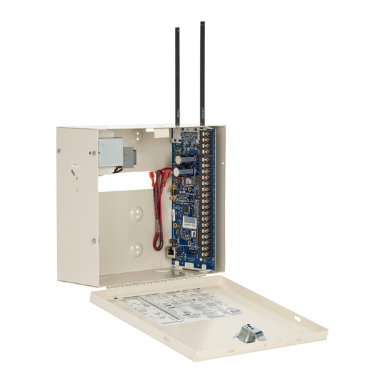
NXG-4 Wiring Diagram Refer to “NXG-8(E) Wiring Diagram” on ANT 2 ANT 1 page 17. The NXG-4 unit functionality is the LAN- same as NXG-8 except that the connections LAN+ are spatially orientated differently. LEARN ULTRASYNC TERM EARTH -BLACK OUTPUT 3- + RED AUX+ BELL-... -
Page 35: Detector Eol Wiring
Detector EOL Wiring Other than the 3K3 end-of-line resistor support, the xGenConnect Grade 2 panels support the following end-of-line resistor value combinations in ohm (*): Combination Tamper (short) 3.3 kΩ 4.7 kΩ 4.1 kΩ Normal 6.6 kΩ 9.4 kΩ 8.2 kΩ Alarm ∞... -
Page 36: Shielding
Shielding The shielding of all shielded cables used in the system should only be connected at one side to one common earthing point in a building. If a shielded LAN cable is routed via more than one plastic device the shielding from incoming and outgoing cable must be connected. -
Page 37: Installing Panel
Installing Panel 1. The xGenConnect should be located away from damp areas (e.g. bathrooms, kitchens), away from sources of heat, dust or interference (e.g. air conditioners, washing machines, dryers, refrigerators) and away from external walls. Due to safety reasons it is not allowed to wall- mount the device higher that 2 meters from the floor. -
Page 38: Installing Legacy Nx Modules
Installing Legacy NX Modules Inside the enclosure there are several 2-holed insertion points. These allows for either vertical or horizontal placement of legacy NX modules. Each insertion point has a larger hole and a smaller hole. 1. The black plastic PCB guides feature a groove to hold an expansion module. - Page 39 Wireless Sensor (NXG-4 only) and Z-Wave Antennas If two black antennas have been provided: 1. Install panel into metal enclosure first. 2. Antenna must be installed vertically for best performance. 3. Each antenna is keyed (shaped differently) and labelled. Antennas are reasonably flexible, do not apply excessive force.
-
Page 40: Plastic Enclosure
NXG-001 Plastic Enclosure The NXG-001 features a DIN rail for mounting xGen modules, a tamper switch, and integrated cable management. The enclosure should be installed in accordance with EN 50131-1 Environmental Class II to provide operating conditions within: • Temperature range: −10 to +55°C. •... -
Page 41: Xgen Metal Enclosure
NXG-003 xGen Metal Enclosure A spare metal enclosure is available for those installations where additional xGen zone and/or output expanders are required or in case a larger backup battery is required. The xGen NXG-003 metal enclosure includes a tamper switch and one metal DIN rail. -
Page 42: Deleting Modules
To enroll a module: 1. Press and hold the LEARN button until the LED next to the button blinks, then release button. (1) D5 LED located next to the LEARN button (2) LEARN button 2. The panel is now in automatic enrollment mode and will search for new devices. - Page 43 This menu will be displayed: 1. System Devices 1. Control 2. Keypad 3. Zone Exp 4. Output Exp 5. Power Supply 2. Interlogix Transmitters 1. Transmitter Number 2. Serial Number 3. User 4. Options 5. Scene 3. Z-Wave Devices 1. Name 2.
-
Page 44: Arming And Disarming Your System
Arming and Disarming Your System You may arm and disarm partitions from an NXG-18xx keypad. Only users with an authorized user code (Level 2 user) will be allowed to use the xGenConnect alarm system. Users with no valid user code (Level 1 user) do not have access as defined by EN 50131-3. -
Page 45: Arm Your System With Nxg-183X Keypad
Arm Your System in Stay Mode Enter a valid PIN code with Stay permissions to unlock the screen. Touch the Stay or Stay + button to arm your system in Stay mode: The icon will change to yellow when alarm system is set in Stay mode. If your system has multi-Partition control enabled, the Stay + button will be displayed. -
Page 46: Disarm Partitions With Nxg-1820-Eur Keypad
Arm Your System in Stay Mode Enter a valid PIN code to unlock the screen. Press the Arm Stay button to arm the system in Stay mode. Using Up (2) and Down (8) buttons, select one of the following Stay Arming modes: •... - Page 47 On this screen touch and hold the appropriate button for 2 seconds to activate Manual Fire Alarm, Manual Medical Alarm, or Manual Panic Alarm. Depending on how your system is programmed, the control room may receive the corresponding event. Check with your control room to determine what action will be taken.
-
Page 48: Programming Methods
Programming Methods Once your devices have been cabled and installed, there are four (4) ways to access and program your xGenConnect system: Method 1: Via DLX900 Management Software – All features can be programmed using a PC with Microsoft Windows 7, 8 and 10. DLX900 allows easier programming of complex sites as the graphical interface can show all options from multiple menus simultaneously. -
Page 49: Method 1: Dlx900 Management Software
Quick Connect using an NXG-1820 / NXG-1830 keypad: 1. Unlock the keypad and access the Programming menu. 2. Navigate to Advanced > Communicator > IP Configuration > IP Options. 3. Navigate to Enable WiFi Internal Access Point. 4. Toggle the option on. 5. - Page 50 manage complex sites. Customer details and all panel programming are stored in a local database. DLX900 supports a variety of connection methods: • Direct connection over LAN • Remote connection over UltraSync (includes LAN or cellular) Connect to xGenConnect using DLX900 on LAN 1.
-
Page 51: Method 2: Web Server
Method 2: Web Server xGenConnect has a built-in web server which makes it easy and simple to set up your system from a web browser instead of the keypad. This features: • Simple forms to set up most commonly used features •... - Page 52 Troubleshooting If you are unable to get an IP address in step 3, then your (wireless) router may not be configured for automatic DHCP or certain security settings may be enabled. • Check your router settings and try again. • On an NXG-1820 touchscreen keypad press Menu, PIN, ENTER, go to Installer >...
- Page 53 3. On the NXG-1820 touchscreen keypad press Menu, PIN, ENTER, go to Installer > Communicator > IP Configuration > IP Options. “Enable UltraSync” should be ticked. Connect to xGenConnect via 4G Cellular and Wi-Fi Router Module Note: Dual path is only available if the panel Ethernet reporting and the cellular module reporting are used.
-
Page 54: Method 3: Ultrasync+ App
2. Alternatively, from a keypad press MENU, go to Program > Communicator > IP Configuration > IP Options > Enable UltraSync: Y. 3. Look at Cell State, it should display “Connected”. Please wait until Cell State displays “Connected”, click Reload to refresh the status. Signal level should be between −89 to −51. - Page 55 Access from the app is disabled by default for security. To allow access these settings must be enabled on your xGenConnect system: • Web Access Code It permits remote access from the UltraSync+ app. Set it to 00000000 to prevent the app from connecting. •...
- Page 56 and “1”. You may also use any other valid user account. Only menus a user has access to will be displayed. Note: EN 50131 Grade 3 default codes are 971300, 123400. 7. Click the Done button to save the details, then Sites to go back. 8.
- Page 57 The menu bar is located along the bottom of the app. Touch the Zones icon (last icon with a dot and wireless signals) to view zone status. • Touch Bypass to ignore a zone or touch it again to restore it to normal operation.
- Page 58 • Touch the Play button under each camera to view the last recorded clip by that camera. Touch the Share button to save or forward the clip. • Touch the Record button to request that camera record a short clip which can be retrieved at a later date.
- Page 59 Events followed with an * have not yet been reported to a control room or have failed to report. Events followed with ** are for events not intending to be reported to a control room. Master users will have access to the full Users menu for creating and managing users.
-
Page 60: Method 4: Nxg-1820 Keypad
• Web Access Passcode must not be 00000000. • Web Access Passcode must be from 4 to 8 digits. • User Name must be entered with a space between the first and last name and with correct capitalization. • If connected by Wired LAN, check the cable is plugged in and that the connection is working. -
Page 61: Programming With Web Pages
Programming with Web Pages Most commonly used features can be programmed from the xGenConnect Web Server > Settings menu. The same menus are displayed from the UltraSync+ app by clicking Menu > Settings. Recommended Items to Change • Installer Code. This is the master key to most features. Always change this to prevent accidental modifications by end-users and unauthorized access to the security system. -
Page 62: Learning Wireless Zones
the Download Access Passcode of 00000000 disallows DLX900 access. Log in to the Web Server and go to Settings > Network to change the code: Learning Wireless Zones 1. Log in to the Web Server. 2. Enter your username and password, by default this is “installer” and “9713”, then click Sign In. - Page 63 3. You should now see a screen similar to the one shown below. 4. Click Settings. 5. Click Zones. 6. Click Learn: 7. Activate the zone. Consult the detector manual for instructions, generally this is performed by opening the detector’s case. This will send a tamper signal to xGenConnect.
- Page 64 Zone Types Table Armed Day Zone Instant Yelping 24 Hour Audible Instant Yelping Entry Exit Delay 1 Entry 1 Yelping Entry Exit Delay 2 Entry 2 Yelping Follower Handover Yelping Instant Instant Yelping 24 Hour Silent Instant Silent Fire Alarm Fire Fire Entry Exit Delay 1 Auto-Bypass Entry 1...
- Page 65 Event Only Event Only Silent Momentary Key Switch Keyswitch Silent Latching Key Switch Keyswitch Silent CO Detector Instant Four Pulse Y Exit Terminate Event Only Silent Holdup Holdup Delay Silent 24 Hour Local Sounder Instant Silent Zone Options Table Zone Options Zone Reporting Zone Contact Options...
- Page 66 Zone Options Zone Reporting Zone Contact Options Water Leakage Y Y Y Y Y 154:WA Low Temp Y Y Y Y Y 159:ZA High Temp Y Y Y Y Y 158:KH Fire Alarm Pull Y Y Y Y Y 115:FA Station Night Mode Y Y Y Y Y...
-
Page 67: Adding A User
Adding a User The xGenConnect system supports up to 256 users. Each user is assigned a PIN code and a user number. This allows them to interact with the system. 1. Log in to the Web Server. 2. Enter your username and password. A master code is required to add users, by default this is “User 1”... -
Page 68: Adding A Keyfob
- Custom users can have additional permissions and settings configured. 9. Click Save. Adding a Keyfob 1. Log in to the Web Server. 2. Click Settings. 3. Click Keyfobs. 4. Use the drop-down menu to select the keyfob number you want to add to the system. - Page 69 partitions. This user number is reported to the Central Monitoring Station when the keyfob is used. 3. Custom permissions > Keyfobs can be restricted to selected partitions. Simple Method: navigate to the User menu and select a suitable Area Group. The arm and disarm buttons on the keyfob will arm/disarm all partitions in the Area Group.
-
Page 70: Programming Cameras
Note: When programming the Scene under the Settings > Scenes menu, the “Scene Trigger” is optional. Select the actions you want to be performed when the scene is “run” by the keyfob. Programming Cameras Adding Cameras Using the New Device Setup The UltraSync+ app has a built-in guide to help you add cameras. - Page 71 • Day/Night settings • IR mode • Recording format / quality / codec • Storage allocation and formatting the micro SD card (if included) • Advanced network configuration • Time zone and daylight savings • Camera naming and text overlay •...
- Page 72 9. Click Scan for New Cameras. “Scanning…” will appear on the button, please wait for the message to disappear. The MAC Address will automatically be filled in. 10. Enter a Camera Name. 11. For Doorbell Camera, enable options for button press if desired. 12.
- Page 73 This is achieved using the Scenes feature. Note: Ensure you can view the Live Stream from the camera before continuing. 1. Log in to the UltraSync+ app. 2. Touch Menu then Settings. 3. Select Scenes under the Settings Selector. 4. Select the Scene to Configure and type a Scene Name. 5.
- Page 74 Viewing event triggered clips in History 1. Touch Menu then HISTORY. 2. Find the video event by using the navigation buttons and scrolling down. Note: For faster searching you can show only Video events by selecting Video in Select Events. 3.
-
Page 75: Configuring Email Reports
Configuring Email Reports 1. Log in to xGenConnect. Use an installer or master user account. 2. Click Settings. 3. Click Channels in the drop-down menu. 4. Click “Select Channel to Configure” where the Format is already set to Email. 5. Enter an email address in the Destination field. 6. - Page 76 OH Configuration Only ip_address:ip_port are mandatory to switch this feature on. Consult your central station for the correct values. ip_address : ip_port : R : L : Polling interval_period : Supervision_port Field description: • ip_address: Public IP address of the OH Net Receiver. •...
- Page 77 reported to OH. If the fault remains present for a longer period, the LAN fault message will be reported after 180 seconds. xGenConnect Installation and Programming Guide...
-
Page 78: Enabling Push Notifications On Smartphone
Enabling Push Notifications on Smartphone Smartphones with the UltraSync+ app can receive push notifications from the panel when system events occur. You will need to have a: • Fully configured and online xGenConnect system. • Fully configured smartphone with internet access and Apple / Google account details. - Page 79 5. Wait for the registration process to complete. Note: A maximum of 13 devices can receive push notifications. Each device will occupy a Channel slot. Each channel will automatically be assigned the corresponding event list number. 6. Optional – select the events to be notified for: a.
- Page 80 Troubleshooting Notifications If notifications are not working: • Check you can see the Arm/Disarm screen of the device you wish to receive notifications from, this ensures you have authority to access the xGenConnect. • Check the xGenConnect has at least one unused channel: Log in to the Web Server and access the Settings >...
- Page 81 • If you have multiple devices registered to receive notifications, each device must have a unique name. This is set in the UltraSync+ app: 1. Touch Menu from the Sites screen. 2. Touch Global Settings. 3. Touch Notification Services. 4. The device name is displayed and can be changed. Removing Notifications Follow the steps above and disable the “Push Notifications”...
- Page 82 4. Click the Channel Number in the drop-down list, your device name will appear. 5. Delete the content of the Destination field. 6. Click Save. 7. Your device will no longer receive notifications from this xGenConnect and the Channel is available to be reused. xGenConnect Installation and Programming Guide...
-
Page 83: Enable Sms Notification (Future Release)
Enable SMS Notification (future release) 1. Open the UltraSync+ app. 2. Click the edit button next to the site you wish to receive notifications from. 3. Click Notification Services. 4. Enable SMS Notifications. 5. Type in the destination mobile phone number. 6. - Page 84 Disable SMS Notification 1. Open the UltraSync+ app. 2. Click the edit button next to the site you wish to stop SMS notifications from. 3. Click Notification Services. 4. Disable SMS Notifications. 5. By switching off SMS Notification, the mobile phone number will be deleted from this device’s Channel.
-
Page 85: Z-Wave Home Automation Hub (Future Release)
Z-Wave Home Automation Hub (future release) If the xGenConnect has been purchased with Z-Wave capabilities, the xGenConnect system is a security enabled Z-Wave controller supporting selected Z-Wave compliant devices including light switches, dimmers, thermostats, and secure/encrypted door locks. A secure Z-Wave controller is required to fully utilize the product. xGenConnect can act as a secure Z-Wave controller. -
Page 86: Programming Z-Wave Siren
5. Click Add. 6. Initiate LINK or ADD mode on Z-Wave device. See your Z-Wave device’s manual for instructions. 7. Click Rooms. 8. Check you can see the device you just added. Click a button such as ON or OFF to verify you can control the device. Programming Z-Wave Siren Some Z-Wave sirens identify themselves to xGenConnect as a true siren, while others identify themselves as binary on\off switches. -
Page 87: Removing Z-Wave Devices
Some Z-wave sirens can follow each keypad beep during Exit Delay and Entry Delay. This is enabled under: 1. Log in to the panel. 2. Click Advanced > System > Siren Options. 3. Enable Z-Wave Siren Chirps Entry and Exit. 4. -
Page 88: Adding Xgenconnect To Existing Z-Wave Network As Secondary Controller
3. Click Remove. 4. Press the include button on the Z-Wave device you want to remove. See your Z-Wave device’s manual for instructions. 5. Device will no longer appear in xGenConnect menus. Adding xGenConnect to existing Z-Wave network as Secondary Controller 1. -
Page 89: Removing Xgenconnect From Existing Z-Wave Network As Secondary Controller
Primary Controller will add xGenConnect to it. xGenConnect Include button and status will update to indicate it has been added as Secondary Controller. 5. Save settings on Primary Controller. Removing xGenConnect from existing Z-Wave network as Secondary Controller 1. Log in to the panel. 2. -
Page 90: Adding Xgenconnect To Existing Z-Wave Network As Primary Controller
4. Press the Exclude button on the xGenConnect (the secondary device): 5. Primary Controller will remove xGenConnect from it. 6. xGenConnect status will update to indicate it has been added as Secondary Controller. 7. Save settings on Primary Controller. Adding xGenConnect to existing Z-Wave network as Primary Controller 1. -
Page 91: Relinquish Primary Control Of Xgenconnect To Another Controller
4. Press the Include button on the xGenConnect (the primary device): 5. xGenConnect now displays “Alarm is Primary Controller” to indicate successful shift: 6. xGenConnect will now be the Primary Z-Wave Controller, and the other network is the Secondary Z-Wave Controller. Relinquish Primary Control of xGenConnect to another Controller 1. - Page 92 3. Check xGenConnect is the primary controller and a secondary controller is already learnt in to xGenConnect. xGenConnect in Primary Controller mode has Add, Remove, Cancel, Shift, and Include buttons. 4. Press the Shift button on xGenConnect (the Primary Controller). 5.
-
Page 93: Creating A Device Association
6. xGenConnect Primary Controller relinquishes control and becomes Secondary Controller. Only the Exclude button is visible indicating the xGenConnect is Secondary Controller. Secondary Controller shifts into Primary Controller. Creating a Device Association Z-Wave supports a feature called “association”. This allows you to control multiple Z-Wave devices such as lights or even a scene from a single Z-Wave on/off switch. -
Page 94: Replacing A Failed Node
Replacing a Failed Node 1. Click Settings > Zwave Maintenance 2. On the Failed Device Selector, click the node to be replaced. 3. Click the Replace button. Status will show “Device Not found in failed list” if the device is working. 4. -
Page 95: Rediscover Z-Wave Nodes
3. Click the Remove button. 4. Status will show “Device Removed” when a failed device is removed. Or “Device Not found in failed list” if the device is working. Rediscover Z-Wave Nodes Z-Wave is a mesh network technology meaning each device can communicate with all nearby devices, and adding more devices generally provides better performance and range. -
Page 96: Backup Z-Wave Network
Backup Z-Wave Network The panel contains a database of all Z-Wave devices and the network configuration. This is separate from the panel programming, and wireless transmitter devices. The Z-Wave Network can be backed up to the internal memory of the panel or downloaded to a computer using DLX900. To perform a backup of the Z-Wave Network: 1. -
Page 97: Send User Pins To Z-Wave Door Lock
Send User PINs to Z-Wave Door Lock xGenConnect can send user PIN codes to a Z-Wave Door Lock. This allows the same PIN codes on the alarm system to operate the door lock. This feature is available to User Types > Engineer, Master, and Custom users with Z-Wave menu access. - Page 98 1. Log in to the panel. 2. Click Settings > Lock PIN Share. 3. Select the Z-Wave Door Lock in the drop-down list. If the lock does not appear, follow instructions on Adding Z-Wave Devices. 4. Wait for the “Building User List – Please Wait” message to be replaced with “Ready”.
-
Page 99: Programming Scenes
Programming Scenes xGenConnect can perform automation features such as recording video clips when a door is opened, turning on a Z-Wave light when motion is detected, and much more. This is achieved by creating a “Scene”. Each scene can perform up to 16 actions when a certain condition is met. - Page 100 13. Test the scene to check if the behavior is desired. Special Scene Triggers: Geosphere / Geolocation Entered Exited UltraSync+ app can send the panel a message when a user’s mobile phone has entered (within 200 meters) or left (outside 300 meters of) a physical area. This can then be used as a scene trigger.
- Page 101 To enable this scene trigger: 1. Open UltraSync+ app. 2. Click (i) Site Info button. 3. Click Location Services. 4. Click Edit Map. 5. Zoom and move the map to the desired location. 6. Click Save Map. 7. Click “Set Sunrise-Sunset Location”, this will load the sunrise and sunset times specific to the selected location into your panel.
- Page 102 User Reporting If a scene performs arm/disarm control of an area, User 99 will be reported to the Central Monitoring Station. xGenConnect Installation and Programming Guide...
-
Page 103: Xgenconnect With Amazon Alexa
xGenConnect with Amazon Alexa xGenConnect is Alexa-enabled. Users can use their voice to turn on a Z-Wave device or run an automation scene. Here are some things you can do: • Use Alexa to voice control your lights on the xGenConnect “Alexa, turn off bedroom lights”... - Page 104 Amazon Alexa integration is not supported in all regions. • Not all Alexa features may be available on this device, learn more at www.interlogix.com. • Amazon Alexa Terms and Conditions do not allow control of garage doors, door locks, or cameras. Arming and disarming is also not allowed. Actions that control these items inside scenes will be skipped, the remainder of the scene will run correctly.
-
Page 105: Xgenconnect Works With Google Assistant
xGenConnect Works with Google Assistant xGenConnect Works with Google Assistant (WWGA) is the new programme for home automation from Google. You will need a Google Account to use Google Nest’s suite of connected home devices and services which includes Google Home Mini, the Home app, and UltraSync connected home services. - Page 106 3. Tap the button Enable Google Assistant. A user is automatically created which will allow Google Assistant to access your panel. Tap Copy to clipboard to copy in the information, and then tap OK. 4. Go to the home screen of the Android device. Tap and hold the home button to start Google Assistant.
- Page 107 5. In the settings page, tap the Assistant tab and select Home Control. The list of devices associated with Google Assistant appears. Tap the “+” button on the lower right to add the new device. 6. In the Add devices page, tap the search icon, type “UltraSync”, tap the UltraSync SmartHome icon.
- Page 108 To view available smart home devices tap Home control > Devices. 8. To interact with the smart device, start Google Assistant by saying “Hey Google” or tap the microphone icon. Speak commands to control the smart devices. xGenConnect Installation and Programming Guide...
- Page 109 For example: “Hey Google. Turn on front door light.” Tested Devices Device Name Family/Model Connectivity Region Thermostat Radio Thermostat CT-100 Z-Wave Lamp Module ZW3101-WCS Z-Wave LED Light Bulb AEOTEC ZW098-A52 Z-Wave Power Switch SCHLAGE 6941R-AU Z-Wave Power Switch AEOTEC ZW096-B09 (AU) Z-Wave xGenConnect Installation and Programming Guide...
-
Page 110: Programming Instructions
Programming Instructions Programming Instructions for System Options Goal Program System Options including time and date, tamper, siren, timers, and service settings. Pre-conditions Time and date are automatically updated using an Internet time server by default, this setting is enabled under Communicator > IP Config. If you want to allow xGenConnect to send diagnostic emails then check email is set up correctly under Communicator >... - Page 111 3. If you wish to update the time and date 4. Go to System and Siren Options 5. Select the settings you want to enable 6. Go to Timers xGenConnect Installation and Programming Guide...
- Page 112 7. Enter the settings for global timers. Note Entry/Exit times are not here, go to Areas > Area Timers. 8. Go to Maintenance and Test 9. Enter a Diagnostic email interval. This is the number of days to wait before sending an email at the specified time.
- Page 113 Web Page xGenConnect Installation and Programming Guide...
-
Page 114: Programming Instructions For Permissions
Programming Instructions for Permissions Goal Create a list of permissions that will restrict users, keypads, and devices to specific parts of the system. Pre-conditions Have programmed or customized Channel Groups, Area Groups, Menus, and Action Groups. Alternatively you can use the preset groups. Programming Sequence 18. - Page 115 Instructions 1. Open Permissions 2. Select the permission number you want to modify 3. Enter a functional name for the permission 4. Select the Groups for each item which will give access to the items selected inside the group. For example, if this permission is assigned to a user, then that user will have access to Arm each of the Areas that are selected inside the Area Group and no others.
-
Page 116: Programming Instructions For Menus
5. Click the Options/Timers tab 6. Select the user options that you want to apply to this permission. Descriptions of each item are available in xGen Reference Guide. Next Program Users or Devices Programming Instructions for Menus Goal Create a list of menus that a user or device has access to on the xGenConnect system. - Page 117 Programming Sequence 13. Menus 11. Permissions 1. User a) Setup → a) Groups → a) Main → b) Security… b) Options/Timers b) Advanced c) History… 13. Menus 11. Permissions d) Communications 12. Area Groups 7. Schedules e) Times… 18. Channel Groups 19.
-
Page 118: Programming Instructions For Holidays
Programming Instructions for Holidays Goal Create a list of holidays to provide or prevent access to the xGenConnect system on the specific dates. Pre-conditions None. Notes • Ticking Holidays in a Schedule for a permission PREVENTS access. • Holiday schedules may impact automation features such as Actions if they are in use. - Page 119 2. Select one of the 4 Holidays available 3. Enter a name for the Holidays 4. Enter the start and end date for each holiday you have Next Program Schedules. Example Office Worker User Permission 1 – All Areas Office Schedule 1 –...
- Page 120 Open Holidays and program the date ranges. Next, go to Schedules and tick “Holidays 1”: xGenConnect Installation and Programming Guide...
-
Page 121: Programming Instructions For Users
Then assign that schedule to the User: Programming Instructions for Users Goal Add/Edit/Remove users from your xGenConnect system. Pre-conditions • Have programmed or customized Permissions. Alternatively you can use the defaults. • Have programmed or customized Schedules. Alternatively you can use the defaults. - Page 122 • The default standard account is “User 2” and PIN 5678. • EN 50131 Grade 3 default codes are 971300, 123400, 567800. Programming Sequence 11. Permissions 7. Schedules 1. User a) Groups → → a) Main b) Options/Timers b) Advanced 13.
- Page 123 6. The Status option determines if that user can interact with the system, or if their access has expired. 7. Click the Advanced tab. 8. You can set the start/end date and time for when this user will have access to the system.
-
Page 124: Programming Instructions For Zones
Web Page Programming Instructions for Zones Goal Program zones and add them to Areas. Pre-conditions None. Notes Use defaults for Zone Types and Zone Options to quickly set up your system. Zones can have one or two profiles. The first profile will be active during the selected schedule, it takes priority over the second profile/schedule. - Page 125 If no schedule is set (or is currently active) in either the first or second zone profile then the zone will be disabled. See the next section for programming custom zones. Programming Sequence 7. Schedules 15. Zone Types 16. Zone options →...
- Page 126 Area, select an Area group with multiple Areas. Alternatively come back to this step later. 7. For a standard installation set the schedule to a preset which is 24 hours every day, holidays should NOT be ticked in this schedule. This will enable the first zone profile.
-
Page 127: Programming Instructions For Custom Zones
Next Zones are assigned to one or more Areas using Area Groups. If necessary, program Areas and Area Groups, then assign an Area Group to each zone (step 6). Programming Instructions for Custom Zones Goal Program zones with advanced customization, including setting zone behavior to follow a schedule or armed/disarmed state. - Page 128 Instructions 1. Go to Zone Type. 2. Go to Zone Options. 3. Select the options you want, the SIA/CID event code can be customized. See xGen Reference Guide for a table of codes. xGenConnect Installation and Programming Guide...
- Page 129 4. Go to Zones. 5. Select a zone number you want to program. 6. Enter a name for the zone. 7. Select the zone type profile you just created. 8. Select the zone options profile you just created. 9. Select an Area Group for the zone. If you want a zone to be in its own Area then select an Area Group with only one Area.
-
Page 130: Programming Instructions For Areas
12. If you are programming a second zone profile, then go to that now and repeat steps 4 to 7. Next Zones are assigned to one or more Areas using Area Groups. If necessary, program Areas and Area Groups, then assign an Area Group to each zone (step 8). - Page 131 Programming Sequence 6. Communicator 5. Channels 18. Channel Groups a) Options → → → b) IP Config c) Ethernet d) Radio e) Dial IP 6. Communicator f) Email 17. Event Lists g) Remote Access h) System Event Reporting 18. Channel Groups 4.
- Page 132 5. For advanced programming you can assign a Schedule and an Area Time Disarm function to occur according to the schedule. Refer to xGen Reference Guide for more details. 6. Go to Area Timers. 7. Enter the timers that apply to this Area. 8.
-
Page 133: Programming Instructions For Schedules
Next Customize Area Groups if needed. Webpage Programming Instructions for Schedules Goal Create a schedule to provide or prevent access to the xGenConnect system on the specific dates and times. Pre-conditions Holidays have been programmed if needed. Notes • Ticking Holidays in a Schedule PREVENTS access on the holiday dates. xGenConnect Installation and Programming Guide... - Page 134 • xGenConnect automatically handles schedules that span midnight (e.g. bakers hours), do not tick the following day of the AM hours. (See xGen Reference Guide for more details.) Programming Sequence 14. Holidays 7. Schedules 18. Channel Groups → → 14. Holidays Instructions 1.
- Page 135 6. To allow an Action to control when this Schedule is active/inactive, select the Follow Action Number. 7. Now the schedule is ready to be assigned to a User or used by another part of the system. xGenConnect Installation and Programming Guide...
- Page 136 Webpage xGenConnect Installation and Programming Guide...
-
Page 137: Programming Instructions For Arm-Disarm
Example For example, you could create a 24/7 schedule and then have this schedule follow an action. Next assign a keypad permission this schedule. Now based on what the action does, we can conditionally enable or disable a keypad. This provides a high level of flexibility and multiple sets of rules using actions can be set up like this. - Page 138 Instructions 1. Create an Area Group and select the Areas you want to be Armed according to the schedule you will create later. 2. Create an Area Group and select the Areas you want to be Disarmed according schedule. This can be the same or different as the Area Group you selected above.
- Page 139 4. Open Users and create a new user. Suggested you provide a descriptive name such as “Auto Arm User” to make troubleshooting in the future easy. 5. Go to the Advanced tab. 6. Select the Permission you created above. If you want a simple Arm-Disarm then leave the Schedule here as Always On.
- Page 140 only for the User. It determines when the User is allowed to perform an Arm- Disarm, not when the Arm-Disarm will occur. 7. Create a Schedule for when you want the Arm-Disarm to occur. xGenConnect Installation and Programming Guide...
- Page 141 8. Open Arm-Disarm. 9. Select the Arm-Disarm number. 10. Enter a descriptive name for this Arm-Disarm. 11. Enter the User number you created above. 12. Select the Schedule for when you want to automatically Arm-Disarm the system. 13. Test the Arm-Disarm to ensure it is working as you want. Example An office with 3 Areas wants to automatically be disarmed during office hours, and armed out of office hours.
-
Page 142: Programming Instructions For Communicator
Arm-Disarm Number 1 – Arm-Disarm Example Schedule 4 – Office Hours → See “Programming Instructions for Mon – Fri Schedules” on page 121 to program 9 AM – 5 PM User 55 – Arm-Disarm User → See “Programming Instructions for Users” on page 109 to program Permission 99 –... - Page 143 Instructions 1. Open Communicator. 2. Select reporting options. 3. Select when you want xGenConnect to perform an automatic communication test. 4. Click IP Config. 5. Edit IP settings for the xGenConnect system, if DHCP is enabled on the xGenConnect and a DHCP server is available, then this screen will automatically be filled in.
- Page 144 - Monitor LAN: This will monitor the physical LAN connection and report communication fail if the cable is disrupted. 6. Click Radio and enter settings if required, this will depend on the SIM card and operator you are using. 7. Click Remote Access 8.
-
Page 145: Programming Instructions For Ultrasync
9. Click System Event Reporting. 10. Select the channel group to send system events (e.g. low battery). Next • Perform tests on each of the communication paths to verify they are functioning correctly. • Program Channels. • Program Channel Groups. •... - Page 146 account and downloading additional software. See further instructions in the User Manual. Instructions 1. Go to Menu 6. Communicator > 3. IP Config. 2. Under sub-menu 12. IP Options, tick the box “Enable UltraSync”. 3. Go to Menu 22. UltraSync. 4.
-
Page 147: Programming Instructions For Event Lists
5. Enter the required details into your device/software. This will usual be your xGenConnect serial number, Web Access Passcode, and a valid Username and PIN code. The xGenConnect serial number can be found in the Device Info menu. 6. Verify the UltraSync service is working by using your device/software to connect your xGenConnect system. - Page 148 Instructions 1. Open Event Lists. 2. Enter a name for the list. 3. Check the events you want to include in the list. Example In this example we have created two lists: Critical and Informational. This allows us to selectively deliver event messages to different destinations. We open up Event Lists and enter the name “Critical”.
-
Page 149: Programming Instructions For Channels
Then we click to Event List 2 and enter the name “Informational”. Tick Opening and Closing, and Autotest Report. Menu 5 – Channels Menu 17 – Event Lists Event List 1 Channel 1 Event Critical Control Room 1 Alarms Event List = 1 Menu 6.11.1.1 or 4 Bypass &... - Page 150 Programming Sequence 6. Communicator 17. Event Lists 5. Channels a) Options → → → b) IP Config c) Ethernet d) Radio e) Dial IP 6. Communicator f) Email 17. Event Lists g) Remote Access h) System Event Reporting 18. Channel Groups 18.
- Page 151 they on this Event List, if they are, then will be routed through this Channel. Events that arrive at this Channel which are not on this list will be blocked. If the Channel is used for push notifications to UltraSync+ app, the Event List number will be the same as the Channel number.
- Page 152 All alarms are reported to Control Room 1 and push notification goes to UltraSync+ app installed on User 1’s smartphone. Control room 1 has a backup receiver. When a channel receives an alarm message, xGenConnect checks that the channel’s Event List includes alarm messages and then attempts to deliver the message via that channel.
-
Page 153: Programming Instructions For Zone Reporting
Programming Instructions for Zone Reporting Goal Direct event messages (e.g. alarm, bypass, tamper) from zones to specific destinations. Pre-conditions • The zone must have valid zone options programmed (see “Programming Instructions for Zones” on page 112), by default you should not need to modify these. - Page 154 Instructions 1. Open the lowest Area number for the Zone. 2. Go to Area Reporting. 3. Enter an account number. 4. Select a valid Channel Group. Done. All zones that are a part of that Area will now report to the selected Channels within the Channel Group.
-
Page 155: Programming Instructions For System Event Reporting
Example Menu 3 – Zones Zone 3 in Alarm Area Group = 1 Zone sends alarm to Area group Menu 5 – Channels Menu 12 – Area Groups Channel 2 Channel 1 Control Room 1 Control Room 1 Area Group 1 Event List = 1 Area 1 Event List = 1... - Page 156 • Take note of the Sequence Attempts under Communicator > System Event Reporting (6.11.2). This is the number of times xGenConnect will attempt the sequence of Channels you set up in this section. Programming Sequence 17. Event Lists → 5. Channels →...
-
Page 157: Programming Instructions For Actions
Example After failing Channel Attempts on the last back up channel, xGenConnect will go back to the first Channel in the chain AC Fail Sequence Attempts = 2 Menu 5 – Channels Menu 6.11.1.1 System Event Channel 1 Channel 2 Reporting Control Room 1 Control Room 1... - Page 158 Programming Sequence 8. Actions 19. Action Groups Events to be → → monitored Instructions 1. Open Actions. 2. Select the Action Number you want to create. 3. Enter a descriptive name for this action. 4. Select the Action Function and the duration (optional) for the Action State. For example, Timed 5 seconds would cause the Action State to activate for 5 seconds when all the conditions in the Event Equation are satisfied.
-
Page 159: Programming Instructions For Action Groups
9. If you want to program an action result, click the Result tab. 10. Select the Category, Type, Start and End Range. 11. Test the Action by satisfying the Event Logic and checking the desired response. Next • Program the device you want to monitor the Action if needed. •... - Page 160 Programming Sequence 8. Actions → 19. Action Groups → 11.Permissions → a) Groups b) Options/Timers 13. Menus 12. Area Groups 18. Channel Groups x. Action Groups 10. Devices → 1. User Outputs a) Main zone expanders, b) Advanced keypads, transmitters 11.
-
Page 161: Programming Instructions For Scenes
Programming Instructions for Scenes Goal Create a scene that performs multiple functions when a certain condition is met. Pre-conditions The schedule you want the Scene to follow needs to be programmed. If you wish to perform Z-Wave Device Actions the Z-Wave device(s) must be learnt in. -
Page 162: Programming Instructions For Outputs
2. Select Event Type and the Area. 3. Select the Schedule that will determine when this Scene is active. 4. Now program the sequence of actions that you want to happen. Example When Exit Delay 1 is running in the Office Area, set Camera 1 to start recording. Programming Instructions for Outputs Goal Turn an output on or off according to an Action. -
Page 163: Combining Actions With Schedules
Combining Actions with Schedules Schedules can control when a user has access, when an automatic Arm-Disarm occurs, when devices can be used, and more. Actions can turn Schedules on and off, making Schedules conditional based on when certain events occur. Action control Action... -
Page 164: User Reporting
5. Trigger each sensor by walking past PIRs, opening and closing reed switches, pressing tamper buttons, etc. Siren will chirp multiple times for each zone triggered. 6. Click Stop. 7. Click History. User Reporting When enabled, quick arming/disarming from the keypad without a PIN code will report user 999 to the Central Monitoring Station. - Page 165 Appendix 1: System Status Messages Various messages may appear on the Status screen of xGenConnect Web Server and UltraSync+ app. System • AC power fail: The security system has lost its electricity power. May take up to 5 min to clear once power restored. •...
- Page 166 Zone Number. Zone Name • In alarm: This zone has triggered a system alarm condition. • Is bypassed: This zone is bypassed (inhibited) and will not activate an alarm. • Chime is set: This zone is part of the chime group. •...
- Page 167 Appendix 2: App and Web Error Messages Various error messages may appear in the xGenConnect Web Server and UltraSync+ app. Advanced/Settings Configuration Menus • “You must select a Menu before you can scroll”: An attempt was made to scroll up or down from the top level menu. •...
- Page 168 Appendix 3: NetworX Modules Compatibility Module part Description Supported by Remarks number xGenConnect NX-7002N-V3 Plug on GSM module for NX-V3 Use NXG-7002 control panels NX-535N Voice speech module NX-535N-V3 Plug on Voice speech module for NX-V3 control panels NX-1048-R-D-EN Multilingual LCD keypad, wireless 868 MHz GEN2, white, incl.
- Page 169 Module part Description Supported by Remarks number xGenConnect NX-586E Direct connect interface for DL900 Up and Download software NX-590NE TCP/IP Internet/Intranet interface module NX-1701E Proximity card reader Requires NX keypad for programming NX-1750 ProxPad proximity reader Requires NX keypad for programming NX-2192E-EUR PinPoint Bus Interface Card...
- Page 170 4. Format 20. Scenes 4. Output Exp 5. Device Number 1. Scene Number 5. Power Supply 6. Destination 2. Scene Name 2. Interlogix 7. Next Channel 3. Activate Schedule Transmitters 8. Event List 4. Activate Event Type 1. Transmitter 9. Attempts 5.
- Page 171 • Single sensor learning. To program a single sensor, go to the menu Program / Devices / Interlogix Transmitters, and select the sensor you want to learn. Enter value “1” in the transmitter serial number field, and then press Enter.
- Page 172 Deleting wireless sensor To delete a single sensor from the system, go to the menu Program / Devices / Interlogix Transmitters, and select the sensor you want to remove. Enter value “0” in the transmitter serial number field, and then press Enter.
- Page 173 Creating a customized company logo requires the following: • Computer or laptop with application to edit and create .bmp files (for example, Microsoft Paint) • DLX900 v5.15 or higher to create .MIF3 file out of the .bmp file • USBUP-EUR-V2 (or DLX900) to flash the NXG-183x keypad with the company logo file (.MIF3) The company logo file can be created by using a computer and a simple application like MS Paint.
- Page 174 6. The Input file selection window appears. Select the .bmp file saved in step 2. 7. Resulting file selection window appears. Provide the location and name for a resulting .mif3 file. Click Save. The resulting MIF3 file can now be used to flash one or more NXG-183x keypads with the customized company logo.
- Page 175 Index programming schedules, 121 programming speech tokens, 65 adding programming system event reporting, 143 Z-Wave devices, 72, 74 programming system options, 97 arming and disarming, 32 programming UltraSync, 133 programming users, 109 programming zone reporting, 141 programming zones, 112 cable requirements, 23 camera motion detection, 88 combining actions with schedules, 151 configuring email reporting, 62...
- Page 176 system options, 97 UltraSync, 133 zone options, 53 users, 109 zone types, 52 zone reporting, 141 Z-Wave devices, 72, 74 zones, 112 xGenConnect terminal diagram, 19 xGenConnect wiring diagram, 17 xGenConnect Installation and Programming Guide...