Sign In
Upload
Manuals
Brands
Thermo Scientific Manuals
Laboratory Equipment
TSQ 9000
Thermo Scientific TSQ 9000 Manuals
Manuals and User Guides for Thermo Scientific TSQ 9000. We have
1
Thermo Scientific TSQ 9000 manual available for free PDF download: Hardware Manual
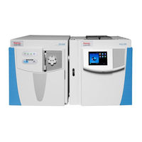
Thermo Scientific TSQ 9000 Hardware Manual (477 pages)
Brand:
Thermo Scientific
| Category:
Laboratory Equipment
| Size: 26.54 MB
Table of Contents
Table of Contents
3
About Your System
13
Preface
13
Related Documentation
14
System Requirements
15
Safety and Special Notices
15
Safety Symbols and Signal Words
16
Hydrogen Safety Precautions
19
Hydrogen Safety Screws on the TSQ 9000
20
Using Hydrogen with TSQ 9000
20
Hydrogen Connection Guidelines
21
Hydrogen Generator
22
Purchasing Hydrogen
22
Valves
22
Properly Storing Hydrogen
23
Hydrogen Safety Codes, Standards and References
25
Hazardous Substances Precautions
26
Biological Hazard Warning Note
26
Venting Toxic Gases
27
Contacting Us
27
To Suggest Changes to Documentation or to Help
28
Chapter 1 Performing Routine Maintenance
29
Maintenance Supplies and Tools
31
Configuring the TSQ 9000 System
32
Powering on the TSQ 9000 System
35
Using the Lights on the TSQ 9000 Instrument
36
Power
36
Vacuum
36
Heaters
36
Busy
37
Powering off the TSQ 9000 System
38
Replacing a Column
40
Ion Source
40
To Connect the Column Using the Spring Loaded Transfer Line Nut
41
Column Measuring Tool
42
Transfer Line Nut and Graphite Vespel Ferrule Orientation
42
Lining up the Column in the Column Measuring Tool
43
Positioning the Septum
43
Inserting the Column into the Transfer Line
44
Positioning the Column in the Transfer Line
45
To Connect the Column Using the Regular Transfer Line Nut
46
Transfer Line Nut and Siltite Ferrule Orientation
47
Pulling the Column Back from the Transfer Line Nut
48
Replacing a Column on a TSQ 9000 System with a VPI and an Extractabrite Ion Source
50
Installing the Column in the GC Inlet
56
Column Flowmeter Connector
58
Maintaining the Foreline Pump
61
Checking the Oil in the Foreline Pump
63
Purging Gas from the Oil in the Foreline Pump
66
Changing the Oil in a Foreline Pump
67
Removing the Ion Source Cartridge for Cleaning
71
Removing the Ion Source Cartridge
72
Components of the Source Exchange Tool
73
Inserting the Ion Volume Tool
74
Twisting the Tool into Place
74
Evacuating the Instrument
75
Pulling down the Vacuum Interlock Handle
76
Pushing the Tool into the Instrument
77
Locking the Tool in Place
78
Pulling the Tool down the Left Track
78
Removing the Tool from the Instrument
80
Exposing the Ion Source Cartridge
81
Inverting the Tool
81
Attaching the Source Holder
82
Disassembling the Ion Source Cartridge
83
Ion Source Cartridge Components
83
Reassembling the Ion Source Cartridge
84
Inserting the Sleeve into the Source Holder
84
Inserting Lens 2 into the Source Sleeve
85
Inserting Lens 3/RF Lens into the Source Sleeve
85
Inserting Lens 1 into the Source Sleeve
86
Inserting the Ion Volume into the Source Sleeve
86
Inserting the Repeller into the Source Sleeve
87
Inserting the Repeller Spring into the Sleeve
88
Inserting the Locking Ring into the Sleeve
89
Reinserting the Ion Source Cartridge
89
Aligning the Tool with the Ion Source Cartridge
90
Reattaching the Ion Source Cartridge to the Tool
91
Removing the Source Holder
92
Maintaining the Calibration Gas Module
97
Refilling the Calibrant Reservoir
98
Replacing a Dual Filament
100
Powering off and Venting the TSQ 9000 System
101
Opening the Manifold Door
102
Removing the Small Glass Manifold Cover
103
Disconnecting the Filament
104
Disconnecting the Filament Board and Wires
104
Replacing the Filament
105
Closing the Manifold Door
107
Replacing the Electron Multiplier
108
Powering off the TSQ 9000 Instrument
109
Disconnecting the Electron Multiplier Cables
110
Disconnecting the Electron Multiplier Plate
111
Reattaching the Electron Multiplier Plate
113
Reconnecting the Electron Multiplier Cables
114
Cleaning Durable Components
116
To Clean the Durable Components
117
Cleaning the CI Ion Volume
118
Cleaning Delicate Components
120
To Clean Delicate Components
121
Cleaning the Filters
122
Removing the Left Rear Wire Mesh Filter
123
Chapter 2 Troubleshooting
125
Using Diagnostics
126
Creating a New Diagnostic Tune File
126
Copying a Tune Type
127
Opening TSQ Series Autotune
127
Naming Your Diagnostic Tune Type
128
Selecting Types of Diagnostics
129
Running a Diagnostic Tune
130
Running an Automatic Tune
130
Investigating Communication Issues
132
Software Is Not Communicating with the TSQ 9000 System
132
Cannot Download Methods to the TSQ 9000 System
132
GC Does Not Start or Is Not Ready
132
Possible Remedies if the GC will Not Start
133
Sample Data Are Not Acquired
134
GC Is Not Communicating with the PC
134
Autosampler Is Not Communicating with the PC
134
Investigating Contamination Issues
135
Chemical Noise Is at M/Z 207, 429, 355, 281
136
Chemical Noise Is at M/Z 43, 57, 71, 85, 99, Etc
136
Spectra Is Showing Solvent Contamination
136
Investigating Filament and Lens Control Issues
138
Filament Has Burned out
138
Filament Does Not Last Long
138
Diagnostics Indicate There Is a Problem with Lens Voltages
138
Investigating Temperature Issues
139
Lens/Source Heater Does Not Heat
140
Transfer Line Does Not Heat
140
Investigating Vacuum Issues
141
An Air Leak Is Detected
142
Foreline Pump Does Not Power on
142
Foreline Pump Powers On, but the System Does Not Pump down
142
Turbomolecular Pump Does Not Power on
142
Turbomolecular Pump Shuts off While in Use
143
Investigating Power Supply Issues
144
TSQ 9000 System Does Not Power on
144
TSQ 9000 System Powers on Temporarily and Trips the Circuit Breaker
144
RF DC Supply Is Outside the Acceptable Range
144
Investigating RF/DC Issues
145
RF Dip Is Incorrect
145
RF/DC System Check Diagnostic Fails
145
Investigating Sensitivity Issues
146
Poor Sensitivity or Sudden Loss in Sensitivity
147
Poor High Mass Response
147
Investigating Stability Issues
148
Mass Assignment Is Unstable
148
Signal Response Is Unstable or Shows Unexpected Drop-Out
148
Investigating Tuning Issues
149
Tune Is Interrupted
150
Cannot Find Calibration Gas Peaks
150
Cannot Perform Detector Gain Calibration
150
Cannot Calibrate Resolution
150
Cannot Perform Mass Calibration
150
An Air Leak Has Been Detected
150
TSQ 9000 Tune Reports an Error While Saving a Tune File
151
Contacting Technical Support
152
Identifying Your TSQ 9000 Instrument
152
Chapter 3 Advanced Troubleshooting
153
Replacing Components of the Analyzer
154
Analyzer Tray
155
Shutting down the TSQ 9000 System
155
Removing the Analyzer Tray from the TSQ 9000 Instrument
157
Disconnecting the Electrometer Board Cable
158
Removing the Small and Large Glass Manifold Covers
158
Removing the Right Side Panel
160
Identifying the Set Screw on the Source Heather Block
161
Removing the Set Screw
161
Removing the Transfer Line Screws
162
Removing the Transfer Line
163
Separating the Transfer Line from the Source Heater Block
163
Removing the Analyzer Tray Components
164
Sliding the Analyzer Tray out of the Instrument
164
To Remove the Analyzer Tray Components from the Tray
164
Finding the Lens Wires between the Quadrupoles
165
Removing the Q3 Quad Assembly from the Analyzer Tray
165
Removing the Analyzer Tray Screws
166
Reattaching the Analyzer Tray Components
167
Removing the Ion Source from the Analyzer Tray
167
To Reattach the Analyzer Tray Components to the Tray
167
Rejoining the Ion Guide to the Quadrupole
168
Replacing the Analyzer Tray in the TSQ 9000 Instrument
170
Reconnecting the Analyzer Tray from the Instrument
172
Restarting the System
173
Ion Guide
175
To Replace the Ion Guide
175
Q1 Entrance Lens and Q1 Entrance Lens Endcap
181
Removing the Collision Cell and Quadrupole 3 from the Analyzer Tray
182
Replacing the Quad Entrance Lens
183
Ion Guide Wire Set
187
To Replace the Ion Guide Wires
187
Q1 Quad, Q3 Quad, and Collision Cell Assemblies
188
Quad 1 and Quad 3 Wire Sets
192
Replacing the Q3 Quad Assembly Wires
193
Attaching the Screws and Washers Correctly
194
Q3 Exit Lens Assembly
195
Replacing Components of the Ion Source
197
Source Heater Block, Lens Heater Block, and Lens/Source Heater
198
Disconnecting the Lens Heater Block Grounding Strap
199
Removing the Source-Repeller Thumbscrews
199
Removing the Repeller Plate and Insulating Spacers
200
Removing the Thumbscrew-Repeller Spacers
200
Disconnecting the Ion Source to the Analyzer Tray
201
Disconnecting the Lens/Source Heater
202
Replacing the Source Heater Block
202
Reattaching the Lens/Source Heater
203
Replacing the Lens Heater Block
203
Reconnecting the Source Block to the Analyzer Tray
204
Sliding the Source Block Onto the Analyzer Tray
204
Reattaching the Source-Repeller Thumbscrews
205
Reconnecting the Lens Heater Block Grounding Strap
205
Locating Wires on the Source Interface Board
206
Source-Repeller Thumbscrews
207
Replacing the Source-Repeller Thumbscrews
208
Thumbscrew-Repeller Spacers
209
To Replace the Thumbscrew-Repeller Spacers
209
Insulating Spacers
211
Repeller Plate
214
Lens Heater Block Grounding Strap
217
Lens Plate and Springs
218
Source to Ion Guide Spacer
220
Ion Source Cartridge
225
To Remove the Extractabrite Ion Source Cartridge
227
Reassembling the Extractabrite Ion Source Cartridge
238
Interlock
243
Removing the Extractabrite Ion Source Cartridge on a TSQ 9000 System Without a Vacuum Interlock
249
Reinserting the Extractabrite Ion Source Cartridge into a TSQ 9000 System Without a Vacuum Interlock
253
Removing the Advanced Ion Source Cartridge on a TSQ 9000 System
256
Removing the Advanced EI Ion Source for Cleaning
259
Reassembling the Advanced EI Ion Source Cartridge
259
Replacing Components of the Source Exchange Tool
262
Replacing Components of the Vacuum Interlock
266
Replacing Components of the Manifold
280
Manifold Door Hinge
281
To Replace the Manifold Door Hinge
281
Freeing the Hinge from the Vacuum Interlock Shield
283
Removing the Lens Driver Board
283
Replacing the Manifold Door Hinge
284
Front Manifold Plate
287
Removing the Vacuum Interlock Knob
287
Disconnecting the Vacuum Interlock Cable
288
Removing the Vacuum Interlock Shield
288
Detaching the Manifold Door
289
Removing the Clamp
290
Removing the Vacuum Interlock Handle
290
Removing the Magnet Yoke and Source Magnet Retainers
291
Removing the Manifold O-Ring
291
Removing the Vent Valve Knob and O-Ring
291
Reattaching the Front Plate O-Ring
292
Reattaching the Magnet Yoke and Source Magnet Retainers
292
Replacing the Front Manifold Plate
292
Reattaching the Metal Block
293
Reattaching the Vent Valve Knob and O-Ring
293
Reattaching the Clamp
294
Reattaching the Vacuum Interlock Cable and Vacuum Interlock Knob
295
Reattaching the Vacuum Interlock Shield
295
Back Manifold Plate
297
Removing the Right Side Panel Screws
297
To Replace the Back Manifold Plate
297
Disconnecting the Power Cables
298
Replacing the Back Manifold Plate
299
Magnet Yoke, Manifold O-Ring, and Source Retainer Magnets
300
Vent Valve Knob and O-Ring
302
To Replace the Vent Valve Knob and O-Ring
302
Replacing Components of the Electron Multiplier
303
Electron Multiplier Plate
304
To Replace the Electron Multiplier Plate
304
Removing the Electrometer Board
305
Removing the Electrometer Shield
305
Removing the Anode Feedthrough
306
Resting the Electron Multiplier Plate on the Worktable
307
Large Feedthroughs
309
To Replace the Large Feedthroughs, O-Rings, and Screws
309
Anode Feedthrough
311
Reinstalling the TSQ 9000 System Software
314
Updating the Firmware on the Instrument
314
Upgrading Software on the Computer
315
Resetting the System
315
System Requirements
316
Installing the Software Set
317
Xcalibur 4.0 Setup Page
317
Replacing the Covers of the TSQ 9000 Instrument
319
Top Cover Panel
320
To Replace the Top Cover Panel of the TSQ 9000 Instrument
320
Left Hand Front Panel and Left Hand Sub Panel
321
Locating the Left Hand Front Panel Screws
321
Finding the Inputs and Screws on the Left Hand Sub Panel
322
Right Side Panel
323
Top Manifold Cover
324
To Replace the Top Manifold Cover
324
Replacing the Chassis Feet
325
Replacing Components of the Front Door
327
Front Door Hinges and Supports
328
Front Door Latch
330
To Replace the Latch on the Front Door
330
Replacing the Boards in the TSQ 9000 Instrument
332
Front and Rear RF Boards and Front and Rear Rod Driver Boards
333
Removing the RF Board from the Instrument
335
Disconnecting the Rod Driver Board 40-Pin Connector
336
Disconnecting the Rod Driver Board from the RF Board
336
Disconnecting the Rod Driver Board 7-Pin Connector
337
Replacing the Rod Driver Board
337
Reinstalling the RF Boards
338
RF Board/Rod Driver Board Kits
339
Replacing the RF Board/Rod Driver Board Kits
340
Reinstalling the RF Board/Rod Driver Board Kits
341
4- Pin Feedthrough
342
To Replace the 4-Pin Feedthrough
342
Disconnecting the Front 4-Pin Connector Wires
343
Disconnecting the Rear 4-Pin Connector Wires
343
Removing the 4-Pin Feedthroughs
345
Removing the Large Glass Manifold Covers
345
Lens Driver Board
347
To Replace the Lens Driver Board
347
Locating the Lens Driver Board
348
Reinstalling the Lens Driver Board
350
20-Pin Feedthrough
351
PC Communication Board, Controller Interface Board, and Support
359
Bracket
359
Removing the Controller Interface Board Support Bracket
361
Removing the Support Bracket Screws
362
Reinstalling the Controller Interface Board
364
Distribution Board
365
To Replace the Distribution Board
365
Disconnecting the Distribution Board
376
Source Interface Board and Heat Shield
379
Electrometer Board Cable
381
Electrometer Board and Shield
383
Replacing the Electrometer Board
384
Replacing the Power Supplies
385
Power Module
386
Locating the TSQ 9000 System Power Cables
387
Dynode and Multiplier Power Supply
390
To Replace the Dynode and Multiplier Power Supply
390
Removing the Power Module Screws
391
Replacing the Calibration Gas Components
395
Calibration Gas Module
396
To Replace the EI Calibration Gas Module
396
Disconnecting the Ethernet Cable from the PC Communication Board
397
Locating the RF Boards and Brackets
398
Calibrant Reservoir Kit
404
Replacing the Calibrant Reservoir and Cover
405
Transfer Line
406
Replacing the Collision Gas Components
410
Disconnecting the Controller Interface Board
414
Identifying the Tubes on the Collision Gas Module
414
Locating the Collision Gas Module
415
Replacing Fans and Filters
418
Front Wire Mesh Filter
420
To Replace the Front Wire Mesh Filter
420
Left Rear Wire Mesh Filter
421
Chassis Cooling Fan and Fan Plenum
422
Air Deflector
428
Turbo Cooling Fan and Turbo Cooling Fan Filter
430
Replacing the Turbomolecular Pump
438
To Install or Replace the Turbomolecular Pump
438
Convectron Gauge and Foreline Adapter with Hose
444
Chapter 4 Upgrade Equipment
447
Advanced EI Ion Source
448
Removing the Source Retainer Magnets
449
Attaching the Magnets and Yoke to the Manifold Door
450
Aligning the Magnets
450
Tightening the Magnets
451
Removing the Extractabrite Ion Source
451
Removing the AEI Source from the Storage
451
Installing the AEI Source
452
Attaching the Wires to the Source Interface Board
452
Storing Extra Source Parts in the AEI Source Case
453
Dust Filter
454
Replacing the Dust Filter
454
CI Reagent Gas Flow Module
455
Locating Components on the Left Hand Sub Panel
456
Removing the Controller Interface Board and PC Communication Board
459
Installing the CI Reagent Gas Flow Module
459
Attaching a CI Tube to the Transfer Line
460
Attaching a CI Tube to the Mixing Chamber and Manifold Wall
460
Attaching the CI Reagent Gas Cable to Distribution Board
461
CI Ion Volume
463
Ion Volumes Available for the TSQ 9000 Mass Spectrometer
463
EI/CI Ion Volume
464
EI/CI Ion Source Cartridge Components
464
Ion Gauge and Tube Shield
465
Assembling the Ion Gauge
466
Connecting the Ion Gauge Cable to the Distribution Board
466
Attaching the O-Ring to the Ion Gauge Tube
467
Installing the Ion Gauge
467
Probe Controller
468
To Install a DIP or DEP
468
Index
469
Advertisement
Advertisement
Related Products
Thermo Scientific TSQ Quantiva
Thermo Scientific TSQ 8000 Evo
Thermo Scientific TSQ Quantum XLS
Thermo Scientific TSQ Quantum XLS Ultra
Thermo Scientific TSQ Quantum GC
Thermo Scientific TSQ Quantis
Thermo Scientific TSQ Fortis
Thermo Scientific TSQ Quantum Access MAX
Thermo Scientific TSQ Vantage
Thermo Scientific TSQ 9610
Thermo Scientific Categories
Laboratory Equipment
Measuring Instruments
Accessories
Refrigerator
Freezer
More Thermo Scientific Manuals
Login
Sign In
OR
Sign in with Facebook
Sign in with Google
Upload manual
Upload from disk
Upload from URL