Sign In
Upload
Manuals
Brands
Keysight Manuals
Analytical Instruments
PD1500A
Keysight PD1500A Manuals
Manuals and User Guides for Keysight PD1500A. We have
2
Keysight PD1500A manuals available for free PDF download: System Installation Manual, Installation And Use Manual
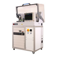
Keysight PD1500A System Installation Manual (96 pages)
Double-Pulse Test Rack and Safety Enclosure
Brand:
Keysight
| Category:
Measuring Instruments
| Size: 2.8 MB
Table of Contents
Using this Double-Pulse Test System Installation Guide
10
Table of Contents
11
1 Site Preparation
16
Customer Responsibilities
16
Rack and Safety Enclosure Dimensions and Weight
16
Tools Required for Installation
16
Double-Pulse Test Rack and Safety Enclosure Location
17
Electrical and Environmental Requirements
18
Connect the DPT Rack and Safety Enclosure to AC Mains
18
AC Power Cord
18
Mains Disconnect
19
Optional Safety Ground Connection
19
Receiving the Rack and Safety Enclosure and Test Instruments
20
Moving the Rack and Safety Enclosure
20
Inventory the Shipment
21
Host Computer System Requirements
23
Static-Safe Handling Procedures
23
PD1500A Documentation
24
Simplified System Diagrams
25
2 Uncrate the Rack and Safety Enclosure
27
Uncrate the Rack and Safety Enclosure
28
Moving the Rack and Safety Enclosure
29
Rack and Safety Enclosure System Hardware Components
30
Re-Crating the Rack and Safety Enclosure for Shipping
31
3 Install Oscilloscope in Safety Enclosure Hood
33
Prepare the Rack and Safety Enclosure
33
Install DSOS104A Oscilloscope Inside the Safety Hood
34
Connect LAN, Power, and Trigger Cables to the Oscilloscope
35
Connect Oscilloscope Probes to Oscilloscope
37
4 Install Test Fixture in the Safety Enclosure Hood
39
Placing the Test Fixture in the Safety Enclosure Hood
40
Connections on Back of Test Fixture
41
Connections on Front of Test Fixture
42
Connect the Waveform Generator to the DPT Test Fixture
42
Connect Heater and Thermocouple to Device under Test (Optional)
43
Second Thermocouple Jack
43
Mounting the Coaxial Shunt Resistor
44
Identify Test Fixture Firmware Version
45
5 Turn-On and Software Installation
48
After Installing Oscilloscope and Test Fixture in the DPT Test Rack
48
Step 1: Connect LAN and Power Cable to Rack
49
Double-Pulse Test System Turn-On and Turn-Off
49
Turning the System off
50
Light Tower Inside the Safety Hood
50
Emergency off Functionality
50
Step 2: Install System Software on Host PC
51
Install IO Libraries Suite on Host PC
51
Download PD1000A System Control Software
51
Step 3: Set Instrument VISA Addresses
52
Instrument Verification
53
Set AC Line Frequency and Date/Time on the B2902A
53
More about IP Addresses and Dot Notation
53
Step 4: Obtain and Install Coaxial Shunt Resistor De-Embedding File
54
Verify D9020ASIA License on the DSOS104 Oscilloscope
54
Annual Characterization of the Coaxial Shunt
55
Obtain the Shunt De-Embedding File
55
Install the De-Embedding Transfer File on the DSOS104 Oscilloscope
57
6 PD1500A Double-Pulse Test System Calibration
59
Initiate Calibration & Compensation Procedures
60
Oscilloscope Probe Offset Compensation
61
Required Equipment
61
Low Frequency Compensation for the 10076C and N2873A Probes
61
Offset Compensation for the N2819A Differential Probe
62
System Calibration Procedure (Autocal)
64
Requirements
64
Gate Voltage Calibration - V
65
Gs /Vge
65
Gate Voltage Source Calibration - V
66
Output
66
Gate Current Calibration - I G Probe
67
Gate Resistance Calibration - R G
68
High Voltage Probe Calibration
69
DS /VCE Probe
69
Clamp Circuit Probe Calibration - VCLAMP Probe
70
PD1000-60002 Protection Probe Calibration - I C
71
PD1000-60002 Protection Probe Calibration - I D /I
71
Coaxial Shunt Resistor Characterization
72
Install the De-Embedding Transfer File on the DSOS104 Oscilloscope
72
Oscilloscope Probe Deskew
73
Connect Probes to Deskew Fixture
73
System Calibration Procedure (Autocal)
74
7 PD1500A System Verification
77
Verification Testing with the SC2080KE Device
78
Equipment Required
78
SCT2080KE Device Data
78
Initial System Verification Test Setup
79
Configure Common Settings
79
Hardware Configuration Hardware Tab
79
Prepare the PD1500A Test Fixture
80
Test Procedure - Standard DPT Test
81
A Simplified System Diagrams and Schematics
85
Connect Oscilloscope Probes to Oscilloscope
88
Simplified DPT Test Schematics
89
BSMA Connectors
91
Final Connection Using a Torque Wrench
92
Separating Connections
93
Inspect and Clean Connectors
94
Connector Cleaning
94
Advertisement
Keysight PD1500A Installation And Use Manual (80 pages)
Si/SiC Test Fixture and Modules
Brand:
Keysight
| Category:
Analytical Instruments
| Size: 10.38 MB
Table of Contents
Table of Contents
13
1 General Information
16
Incoming Inspection for Double-Pulse Test Fixture and Modules
16
Preparation for Use
16
Static-Safe Handling Procedures
16
PD1000A Test Fixture for the PD1500A Double-Pulse Test System
17
Connections on Back of Test Fixture
17
Test Fixture Modules
19
Standard Double-Pulse Test Setup
21
Use These Double-Pulse Test Modules and Oscilloscope Probes
21
Clamp Test Setup
22
Use These Double-Pulse Test Modules and Oscilloscope Probes
22
Reverse Recovery Double-Pulse Test Setup
23
Use These Double-Pulse Test Modules and Oscilloscope Probes
23
2 Double-Pulse Test Preparation
25
Connect the Waveform Generator to the Double-Pulse Test Fixture
25
Connect Heater and Thermocouple to Device under Test (Optional)
26
Second Thermocouple Jack
26
Mounting the Coaxial Shunt Resistor
27
Install Test Modules on the Main Test Fixture
28
Install Double-Pulse Test Modules on the Test Fixture in this Order
30
For both TO-247 and D 2 PAK Device DUT Types
31
Clamp Circuit Module
32
When to Use the PD1000-66505 Clamp Circuit Module
33
Using the Clamp Circuit Module
33
How the Clamp Circuit Works
33
Gate Drive Modules (Low-Side and High-Side)
34
Connect Oscilloscope Probes to Oscilloscope
37
Connect Probes to the Double-Pulse Test Modules
38
Connect the 10076C High Voltage Probe
40
Coaxial Shunt Resistor and PD1000-60002 Protection Probe
41
Cleaning the Protection Probe
42
3 DUT Test Module for Si/Sic T0-247-3 and -4 Devices
43
General Module Information
44
Install Two Transistors on the TO-247-3 and -4 DUT Modules
45
Installing and Using External Inductors
48
Testing Devices with TO-220 Packaging
49
4 DUT Test Module for Si/Sic D
51
PAK 7-Pin Devices
51
General Information
52
500 D PAK Devices
53
D 2 PAK Devices
53
Typical 7-Pin DPAK SMD Device
53
Install Two Transistors on the Module
53
Install Device Heater and Thermocouple on SMD Device
55
Install Chip Devices on the Module
56
A Using the Device Heater
57
Adding Kapton (Polyimide) Tape to TO-247-3 and -4 Devices
58
Device Heater Theory of Operation
59
Heater Stability
61
Using the Device Heater
61
Configuring Temperature Control Settings (Hardware Configuration)
61
Activating the Heater and Setting Test Temperatures
62
A Custom Gate Drive Resistors
65
Custom Gate Resistor Test Modules
65
How to Test the Gate Drive Resistor to Ensure Proper Operation
67
Selecting Gate Drive Resistors
68
Low Gate Resistor Values
68
High Gate Resistor Values
68
Optimal Gate Resistor Value
69
B Installing Surface-Mount Devices
75
Using a Hot Air Solder Reflow Tool
75
Using a Small-Tip Soldering Iron
76
Advertisement
Related Products
Keysight PD1000A
Keysight PD1550A
Keysight PXA N9030A
Keysight PNA N5227A
Keysight PXIe Series
Keysight P9243A
Keysight P5004A
Keysight P937*A series
keysight PNA Series
keysight PNA-X Series
Keysight Categories
Measuring Instruments
Test Equipment
Multimeter
Control Unit
Portable Generator
More Keysight Manuals
Login
Sign In
OR
Sign in with Facebook
Sign in with Google
Upload manual
Upload from disk
Upload from URL