Table of Contents
Advertisement
Quick Links
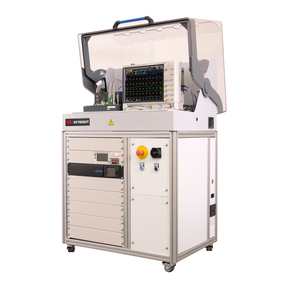
Keysight PD1500A
Double-Pulse Test Rack and
Safety Enclosure
Provides detailed information to install the Double-
Pulse Test Rack and Safety Enclosure at a customer
site. The Rack and Safety Enclosure is used with the
PD1500A Dynamic Power Device Analyzer/Double-
Pulse Tester.
System Installation
Guide
Advertisement
Table of Contents

Related Manuals for Keysight PD1500A


Summary of Contents for Keysight PD1500A
- Page 1 Double-Pulse Test Rack and Safety Enclosure Provides detailed information to install the Double- Pulse Test Rack and Safety Enclosure at a customer site. The Rack and Safety Enclosure is used with the PD1500A Dynamic Power Device Analyzer/Double- Pulse Tester. System Installation Guide...
- Page 3 Warranty © Keysight Technologies, Inc. 2020 No part of this manual may be repro- To contact Keysight for sales and techni- THE MATERIAL CONTAINED IN THIS duced in any form or by any means cal support, refer to the support links on DOCUMENT IS PROVIDED “AS IS,”...
- Page 4 Return the product to a precautions or with specific warnings containers of such liquids. Keysight Sales and Service Office to or operating instructions in the product ensure that safety features are main- manuals violates safety standards of Cleaning tained.
- Page 5 Indicates that antistatic To return unwanted products, contact precautions should be your local Keysight office for more taken. information. DANGER: High Voltage Hot Surface; DO NOT...
- Page 6 The use of any other accessory is not recommended or supported. Intended Use of Equipment The Keysight Double-Pulse Test Rack and Safety Enclosure and Test Fixtures, along with the recommended accessories, are intended to be used for the PD1500A Dynamic Power Device...
- Page 7 Failure to comply with these precautions or with specific warnings elsewhere in this manual may impair the protections provided by the system. In addition, it violates safety standards of design, manufacture, and intended use of the system. Keysight Technologies assumes no liability for customer’s failure to comply with these requirements.
- Page 8 • Instruments, probes or cables that appear damaged or defective should be made inoperative and secured against unintended operation until they can be repaired by qualified service personnel. Return the product to a Keysight Technologies sales or service office for service and repair to ensure that safety features are maintained.
- Page 9 PD1500A Dynamic Power Device Analyzer/ Double-Pulse Test System Documentation Install the PD1500A Double-Pulse Test System PD1500A DPT Rack and Safety Enclosure Installation Guide Install and use Install, configure Operate and the Si/SiC Test and use the maintain the Fixture and...
-
Page 10: Using This Double-Pulse Test System Installation Guide
Using this Double-Pulse Test System Installation Guide Using this Double-Pulse Test System Installation Guide This manual describes the installation process for the Keysight PD1500A Dynamic Power Device Analyzer/Double-Pulse Tester (DPT). Because this is a test system (as opposed to an individual test instrument), the system is shipped in several containers and must be assembled on the customer’s site. -
Page 11: Table Of Contents
PD1500A Documentation ........ - Page 12 Install the De-Embedding Transfer File on the DSOS104 Oscilloscope . . . 57 6 PD1500A Double-Pulse Test System Calibration Initiate Calibration & Compensation Procedures ..... 60 Oscilloscope Probe Offset Compensation .
- Page 13 Hardware Configuration Hardware Tab ......79 Prepare the PD1500A Test Fixture ......80 Test Procedure - Standard DPT Test .
- Page 14 Keysight Double-Pulse Test System Installation Guide...
- Page 15 See “Customer Responsibilities” on page 16. This System Installation Guide provides step-by-step instructions to assemble and install the PD1500A Dynamic Power Device Analyzer/Double-Pulse Tester. Note that the PD1500A is part of the overall PD1000A Power Device Measurement System for Advanced Modeling. In this chapter:...
-
Page 16: Site Preparation
Site Preparation Customer Responsibilities Customer Responsibilities This System Installation Guide provides instructions for a Keysight-trained Application Engineer to install the Keysight PD1500A DPT System Rack and Safety Enclosure. page 20 Receive the Double-Pulse Test System (multiple shipping containers). See ... -
Page 17: Double-Pulse Test Rack And Safety Enclosure Location
Safety Enclosure hood. The Air Intake fans on the rack sides are temperature controlled. They turn on only when the temperature in the lower portion of the rack exceeds approximately 30 ° C. Keysight Double-Pulse Test System Installation Guide... -
Page 18: Electrical And Environmental Requirements
2.5 m long, Type A, IEC-60320 C19 to Type B Free End) is supplied with the PD1500A Rack and Safety Enclosure. A qualified electrician must either: – permanently hard wire the free end to the AC power source or –... -
Page 19: Mains Disconnect
This DPT Rack and Safety Enclosure must be grounded properly for proper operation and safety. Because the rack is connected to the AC mains by a plug/socket connection, Keysight recommends a redundant permanent earth ground connection to reduce the risk of electric shock. -
Page 20: Receiving The Rack And Safety Enclosure And Test Instruments
Inspect the rack and instruments for damage (scratches, dents, bent pieces, etc.). If the rack or any instrument is damaged, notify the carrier and the nearest Keysight Technologies Sales and Service office immediately. Moving the Rack and Safety Enclosure On initial receipt, the Rack and Safety Enclosure exceeds 150 kg (330 lbs). -
Page 21: Inventory The Shipment
-- 8121-3445 2.5 m C19 power cord for N. America only, or -- 8121-3356 2.5 m C19 power cord for all other countries – Keysight 33512B Waveform Generator with ARB (installed in back of rack) – Keysight B2902A Precision Source/Measurement Unit (pre-installed) –... - Page 22 – 8710-1582, 0.56 N-m (5 lb-in) 5/16 in Break-over torque wrench for SMA – PD1000 -00004 A set of hand tools is also provided for use when assembling the PD1500A DPT Test System The following cables and adapters are used only for the AutoCal procedure: –...
-
Page 23: Host Computer System Requirements
Available hard disk space 1.5 GB available hard disk space, includes: 1 GB available for Microsoft .NET Framework 4.5.2 100 MB for Keysight IO Libraries Suite Video: Screen resolution -- Full HD (1920x1080) at 100%. Support for DirectX 9 graphics with 128 MB graphics memory recommended 1. -
Page 24: Pd1500A Documentation
PD1500 Test Rack and Safety Enclosure. PN: PD1500-90003 - PD1500A Si/SiC Test Fixture User Guide: Provides detailed information to install and use the Double-Pulse Test Modules for testing Si/SiC devices in the DPT Test Fixture. PN: PD1500-90004 Documentation and software are available at: www.keysight.com/find/PD1500A... -
Page 25: Simplified System Diagrams
Simplified System Diagrams Site Preparation Simplified System Diagrams Refer to Appendix A, “Simplified System Diagrams and Schematics on page page 85 for diagrams. These diagrams illustrate the overall system wiring. Keysight Double-Pulse Test System Installation Guide... - Page 26 Site Preparation Simplified System Diagrams Keysight Double-Pulse Test System Installation Guide...
-
Page 27: Uncrate The Rack And Safety Enclosure
Double-Pulse Test System Installation Guide Uncrate the Rack and Safety Enclosure The Double-Pulse Test (DPT) Rack and Safety Enclosure is the largest of all of the items shipped for the system. Unpack all of the other instruments, rack mount kits, cables, etc. and have them ready for installation in the rack. This chapter describes how to uncrate the DPT Rack and Safety Enclosure. -
Page 28: Uncrate The Rack And Safety Enclosure
Uncrate the Rack and Safety Enclosure Uncrate the Rack and Safety Enclosure Use the following procedure to remove the rack from the shipping crate. Keysight recommends using two people to uncrate the Rack and Safety Enclosure. Wear work gloves to protect against splinters. -
Page 29: Moving The Rack And Safety Enclosure
The rack’s center of gravity is high and the rack might tilt over when moving. Also, the DSOS104 Oscilloscope and the DPT Test Fixture are not secured to the top of the rack. They may slide around if the rack tips. Keysight Double-Pulse Test System Installation Guide... -
Page 30: Rack And Safety Enclosure System Hardware Components
Fixture and test modules, various cables, oscilloscope probes, and other miscellaneous parts. 1 The “T” wrench is used only during initial installation of the PD1500A Rack and Safety Enclosure. Under normal use, the Safety Hood remains locked when the system is powered and functional. Refer to the PD1500A Test Rack and Safety Enclosure Operation and General Maintenance Guide for information. -
Page 31: Re-Crating The Rack And Safety Enclosure For Shipping
Re-crating the Rack and Safety Enclosure for Shipping If you need to ship the Double-Pulse Test system to a different location – beyond where it can be rolled on its casters – prepare the PD1500A system for shipping per the following instructions. - Page 32 Uncrate the Rack and Safety Enclosure Re-crating the Rack and Safety Enclosure for Shipping Keysight Double-Pulse Test System Installation Guide...
-
Page 33: Install Oscilloscope In Safety Enclosure Hood
High Voltage Power Supply are already installed inside the Double-Pulse Test Rack and Safety Enclosure. The Keysight DSOS104A Oscilloscope and the DPT Test Fixture sit on top of the Work Surface inside the Safety Hood and must be installed by the Keysight AE. -
Page 34: Install Dsos104A Oscilloscope Inside The Safety Hood
Feet must rest on work surface. Minimum 75 mm Minimum Minimum 25 mm 25 mm Top View of Oscilloscope Figure 2 Placing the Oscilloscope Inside the Safety Hood -- Clearances Keysight Double-Pulse Test System Installation Guide... -
Page 35: Connect Lan, Power, And Trigger Cables To The Oscilloscope
Control Software on the Host Computer cannot communicate with the oscilloscope or other test equipment. You may need the oscilloscope keyboard and mouse for initial setup. Otherwise, do not plug a keyboard or mouse into the oscilloscope. Keysight Double-Pulse Test System Installation Guide... - Page 36 Tabs under the front feet of the oscilloscope can be flipped out to tilt the oscilloscope for easier viewing. Figure 4 Latching the Front Feet Ensure the scope power cord, LAN cables, trigger BNC cable do not interfere with closing the safety hood. Keysight Double-Pulse Test System Installation Guide...
-
Page 37: Connect Oscilloscope Probes To Oscilloscope
CLAMP 2 Use the 0.56 N-m (5 lb-in) 5/16 in. SMA Break-over torque wrench (provided with the PD1500A system) to tighten the SMA cable connector to the PD1000-60002 Protection Probe. Failure to do so might cause extensive ringing in the DPT measurements. See appendix for details. - Page 38 Install Oscilloscope in Safety Enclosure Hood Connect Oscilloscope Probes to Oscilloscope Keysight Double-Pulse Test System Installation Guide...
-
Page 39: Install Test Fixture In The Safety Enclosure Hood
Double-Pulse Test System Installation Guide Install Test Fixture in the Safety Enclosure Hood In This Chapter: Placing the Test Fixture in the Safety Enclosure Hood page 40 Connections on Back of Test Fixture page 41 Connections on Front of Test Fixture page 42 Connect the Waveform Generator to the DPT Test Fixture... -
Page 40: Placing The Test Fixture In The Safety Enclosure Hood
Placing the Test Fixture inside the Safety Hood There is a fan on the right side of the Test Fixture. Make certain there is adequate air flow. At least 2 inches between the Test Fixture and the DSOS104 Oscilloscope. Keysight Double-Pulse Test System Installation Guide... -
Page 41: Connections On Back Of Test Fixture
Safety Box (under work surface) Connector reserved for future use. Do not attempt to connect anything here. Figure 7 Back of Test Fixture and Cable Installation Figure 8 Back of Test Fixture with Cables Keysight Double-Pulse Test System Installation Guide... -
Page 42: Connections On Front Of Test Fixture
PD1000-68701Test Fixture Use the 0.56 N-m (5 lb-in) 5/16 in. SMA Break-over torque wrench (provided with the PD1500A system) to tighten the SMA connector on the test fixture and the BNC-SMA cable to the PD1000-60002 Protection Probe. Failure to do so might cause extensive ringing in the DPT measurements. -
Page 43: Connect Heater And Thermocouple To Device Under Test (Optional)
If you want to use the heater and thermocouple, they must be connected to the Test Fixture before powering-up the PD1500A system. Reboot the PD15000A if the heater is not detected. Refer to Chapters 2 (TO-247 devices) and 3 (SMD devices) for instructions to attach the heater and thermocouple to the DUT. -
Page 44: Mounting The Coaxial Shunt Resistor
Install Test Fixture in the Safety Enclosure Hood Mounting the Coaxial Shunt Resistor Mounting the Coaxial Shunt Resistor Two characterized coaxial shunt resistors are available for the PD1500A: – PD1000-61901, 0.01 (supplied with PD1500A) – PD1000-61902, 0.1 (optional) The coaxial shunt must be installed on the DUT modules. -
Page 45: Identify Test Fixture Firmware Version
3 Select Hardware Configuration for Double-Pulse Test Control. 4 Select the Hardware Configuration > Hardware tab opens the following dialog. Check Button used to verify communication with test instruments. See NOTE on next page. Figure 12 Double-Pulse Test Hardware Configuration Screen Keysight Double-Pulse Test System Installation Guide... - Page 46 If any or all of them are red, it indicates a failure to communicate. IMPORTANT: If you are using a laptop computer, turn the Wireless Network Connection off in the laptop before attempting to connect to the PD1500A system. Contact your local Keysight Application Engineer to update the Test Fixture firmware.
- Page 47 Obtain the Shunt De-embedding file page 55 Install the De-Embedding Transfer File on the DSOS104 Oscilloscope page 57 IMPORTANT: If you are using a laptop computer, turn the Wireless Network Connection off in the laptop before attempting to connect to the PD1500A system.
-
Page 48: Turn-On And Software Installation
After installing the DSOS104A Oscilloscope and PD1000A Test Fixture, do the following: 1 Install Keysight IO Libraries on the host PC. 2 Install the PD1000A Control Software on the host computer. Complete details for installing the software are provided in the PD1000A Startup Guide or the PD1500A Software Guide. -
Page 49: Step 1: Connect Lan And Power Cable To Rack
5 Press the Reset button. Test instruments turn on. You should hear a few clicks as the safety relays energize. The system is now operational. 6 If the individual test instruments are not already turned on, turn them on now. Keysight Double-Pulse Test System Installation Guide... -
Page 50: Turning The System Off
After about 1 second the high voltage source shuts off by interrupting the main power line. - To reset, pull out to release the Emergency Off button. Reset the Emergency Off circuit by pressing the Quit button. Keysight Double-Pulse Test System Installation Guide... -
Page 51: Step 2: Install System Software On Host Pc
Easy EXPERT is running. Run EasyEXPERT before using Connection Expert. Download PD1000A System Control Software The PD1000A System Control Software may be downloaded from Keysight at any time. Download the software from the following website: www.keysight.com/find/PD1000A The PD1500A Double-Pulse Tester software is one part of the PD1000A Power Device Measurement System for Advanced Modeling Control Software. -
Page 52: Step 3: Set Instrument Visa Addresses
156.140.93.168 for the DSOS104 Oscilloscope IP Address. Do NOT use the 192.168.25.2 address. 4 On the DSOS104 oscilloscope, run the Connection Expert utility in Keysight IO Libraries Suite to specify the addresses and verify communication with the other test instruments. -
Page 53: Instrument Verification
– Run Interactive IO to verify communication with the instruments. Set AC Line Frequency and Date/Time on the B2902A The Keysight B2902A Source Measure Unit (SMU) is used only for the system calibration. Its factory default line frequency is set to 50 Hz and must be changed to 60 Hz in those countries with a 60 Hz line frequency. -
Page 54: Step 4: Obtain And Install Coaxial Shunt Resistor De-Embedding File
DSOS104A Oscilloscope. Verify D9020ASIA License on the DSOS104 Oscilloscope Keysight’s D9020ASIA Advanced Signal Integrity Software license should be installed on the DSOS104 Oscilloscope and the license activated at the factory. Verify the installation and activation with the following procedure. License activation instructions and certificate are provided with your DSOS104 Oscilloscope. -
Page 55: Annual Characterization Of The Coaxial Shunt
7 Unzip the file to a temporary location. 0960-3431 is the Keysight part number for the uncalibrated shunt itself. If you need to order additional shunts, order Keysight part number PD1000-61901. This includes a characterized shunt, mounting bushing, serial number, and installation instructions. - Page 56 Turn-on and Software Installation Step 4: Obtain and Install Coaxial Shunt Resistor De-Embedding File Figure 5 Portion of a .TF2 Sample File Keysight Double-Pulse Test System Installation Guide...
-
Page 57: Install The De-Embedding Transfer File On The Dsos104 Oscilloscope
2 In the PD1000A Control Software, type the complete path and .tf2 file name into the Double-Pulse Measurement Control > Settings > Instrument Configuration > De-embedding File field. Refer to the PD1500A Control Software Guide for additional information. The oscilloscope channel you specify for the Output Current I the DPT Control Software Hardware Configuration screen is the channel that the Coaxial Shunt De-embedding is applied to. - Page 58 Turn-on and Software Installation Step 4: Obtain and Install Coaxial Shunt Resistor De-Embedding File Keysight Double-Pulse Test System Installation Guide...
-
Page 59: Pd1500A Double-Pulse Test System Calibration
– Coaxial Shunt Resistor Characterization & De-embedding. Characterization should be performed annually. A De-embedding file will be available for Keysight InfoLine and should be installed in the oscilloscope immediately after characterization. See “Step 4: Obtain and Install Coaxial Shunt Resistor De-Embedding File” on page 54. -
Page 60: Initiate Calibration & Compensation Procedures
PD1500A Double-Pulse Test System Calibration Initiate Calibration & Compensation Procedures From the PD1000A Control Software, select the Double-Pulse Test Control tab. From the Settings drop-down menu, select Calibration & Compensation. Be careful to follow all instructions. Keysight Double-Pulse Test System Installation Guide... -
Page 61: Oscilloscope Probe Offset Compensation
Oscilloscope Probe Offset Compensation PD1500A Double-Pulse Test System Calibration Oscilloscope Probe Offset Compensation As the first step calibrating the Double-Pulse Test system, the oscilloscope probes must be adjusted for low frequency compensation. For this, the 10076C and N2873A passive probes have built-in compensation RC divider networks. -
Page 62: Offset Compensation For The N2819A Differential Probe
PD1500A Double-Pulse Test System Calibration Oscilloscope Probe Offset Compensation 4 Adjust so that the square wave on the oscilloscope screen looks square. Under Compensated Over Compensated Optimum Due to the 100:1 divider of the 10076C High Voltage Probe, the signal will appear to be very noisy. Therefore, it is beneficial to enable averaging in the Setup >... - Page 63 Oscilloscope Probe Offset Compensation PD1500A Double-Pulse Test System Calibration 4 Press the channel button for the probe and set the oscilloscope channel to DC Coupled mode. 5 Set the oscilloscope to Averaging mode (Setup > Acquisition... > Averaging Enabled, x8 or higher) to reduce oscilloscope noise, if needed.
-
Page 64: System Calibration Procedure (Autocal)
PD1500A Double-Pulse Test System Calibration System Calibration Procedure (Autocal) System Calibration Procedure (Autocal) Follow all on-screen instructions. Damage to the Test Modules is possible if instructions are not followed. IMPORTANT: After calibration and before running any Double-Pulse Test, make certain the Low-Side Gate Drive Modules have the V/NC jumper installed and the I/NO jumper removed. -
Page 65: Gate Voltage Calibration - V
After setting up the hardware as described above, click Start to perform the calibration and continue to the Gate Voltage Source Calibration. A strip of 10 header jumpers (Keysight part number 1258-0225) were supplied with your PD1500A for use during calibration. -
Page 66: Gate Voltage Source Calibration - V
After setting up the hardware as described above, click Start to perform the calibration and continue to the Gate Current Calibration. A strip of 10 header jumpers (Keysight part number 1258-0225) were supplied with your PD1500A for use during calibration. -
Page 67: Gate Current Calibration - I G Probe
After setting up the hardware as described above, click Start to perform the calibration and continue to the Gate Resistance Calibration. A strip of 10 header jumpers (Keysight part number 1258-0225) were supplied with your PD1500A for use during calibration. -
Page 68: Gate Resistance Calibration - R G
PD1500A Double-Pulse Test System Calibration System Calibration Procedure (Autocal) Gate Resistance Calibration – R This step is required when installing custom gate resistors on the High-Side and Low-Side Gate Drive modules. Hardware Setup: See Figure 9 below. – Install the I/NO Jumper on the Low-Side Gate Drive Module. -
Page 69: High Voltage Probe Calibration
– Install a PD1000-66843 High-Side Gate Drive Module (0 Gate Resistor) – Install a 1200 V FET (for example, the SCT2080KE FET supplied with the PD1500A) in the High-Side position of the DUT module. – Remove any FET in the Low-Side position of the DUT Module. -
Page 70: Clamp Circuit Probe Calibration - Vclamp Probe
Hardware Setup: See Figure 11 below. – Install the PD1000-66805 Clamp Circuit Module in the PD1500A Test Fixture. If you are not using or calibrating the Clamp Module, press the Skip button to skip this step and proceed to the Protection Probe Calibration. -
Page 71: Pd1000-60002 Protection Probe Calibration - I C
Use the 0.56 N-m (5 lb-in) 5/16 in. SMA Break-over torque wrench (provided with the PD1500A system) to tighten the cable to the PD1000-60002 Protection Probe. Failure to do so might cause extensive ringing in the DPT measurements. -
Page 72: Coaxial Shunt Resistor Characterization
DUT Test Module and shipped to a Keysight Service Center for characterization. This should be done annually. After the shunt is characterized, Keysight will return the shunt to you. This provides the latest characterization .tf2 file. Download the file from the Keysight Infoline website and install it in the DSOS104 oscilloscope. -
Page 73: Oscilloscope Probe Deskew
Oscilloscope Probe Deskew PD1500A Double-Pulse Test System Calibration Oscilloscope Probe Deskew Connect Probes to Deskew Fixture After the Oscilloscope Probe Compensation and System Calibration, the last step is to run Deskew. Deskew has the greatest impact on both On and Off Delay times and hence affects the total Switching Time. -
Page 74: System Calibration Procedure (Autocal)
Coaxial Shunt Resistor on the DUT Test Module. Figure 14 Oscilloscope Probes Connected to Deskew Fixture IMPORTANT: The N2918A Differential Probe must face to the left; the Keysight logo must face toward the V probe connector. CLAMP Procedure: 1 After setting up the oscilloscope probes in the Deskew fixture, click Start to perform Deskew calibration. - Page 75 Oscilloscope Probe Deskew PD1500A Double-Pulse Test System Calibration Keysight Double-Pulse Test System Installation Guide...
- Page 76 PD1500A Double-Pulse Test System Calibration Oscilloscope Probe Deskew Keysight Double-Pulse Test System Installation Guide...
-
Page 77: Pd1500A System Verification
– All documentation is available (www.keysight.com/find/PD1500A) – Appropriate ac power is available for the system – Keysight IO Libraries installed in the customer’s host PC – Latest version of PD1000A Control Software installed in the customer’s host PC (www.keysight.com/find/PD1500A) -
Page 78: Verification Testing With The Sc2080Ke Device
Two Rohm SC2080KE, TO-247, 3-pin N-Channel SiC Power MOSFETs were provided with the Keysight PD1500A Double-Pulse Test system. These FETS are provided as a way to test the final PD1500A system and ensure it is working correctly. This chapter describes initial testing the SC2080 devices and expected results. -
Page 79: Initial System Verification Test Setup
Check 2. Click the Button to verify communication with test instruments. Figure 15 PD1500A Hardware Configuration Screen b Refer to the PD1500A Control Software Guide for detailed information about the PD1500A Hardware Configuration. Keysight PD500A Double-Pulse Test System Installation Guide... -
Page 80: Prepare The Pd1500A Test Fixture
Verification Testing with the SC2080KE Device Prepare the PD1500A Test Fixture For detailed information about setting-up the PD1500A Test Fixture, refer to the PD1500A Si/SiC Test Fixture User Guide. IMPORTANT: If you are using a laptop computer, turn the Wireless Network Connection off in the laptop before connecting to the PD1500A system. -
Page 81: Test Procedure - Standard Dpt Test
– Oscilloscope Probe Compensation – Oscilloscope Probe Deskew If this is the first time the PD1500A system is tested or used, perform all system calibration steps. See “PD1500A Double-Pulse Test System Calibration” on page 59. This ensures the Gate Drive modules, Clamp Module, and all probes are functional and calibrated. - Page 82 Use Test Pulse: Checked Extract Characteristics: Checked (Optional but recommended) Extract IV Curve: Leave unchecked Vgs Resolution: 1 V (not available if Extract IV Curve is unchecked) Extract Gate Charge: Leave unchecked for 0 and 10 Gate Drive modules –...
- Page 83 Test Procedure - Standard DPT Test PD1500A System Verification b Parameters c Signal Levels and Times Keysight PD500A Double-Pulse Test System Installation Guide...
- Page 84 Also, check the files saved in the Global Settings > Output Directory folder that you specified. Sample test result files and a test setup file are available in the following folders: Documents > Keysight > PD1000A > Examples > results > setup Keysight PD500A Double-Pulse Test System Installation Guide...
-
Page 85: A Simplified System Diagrams And Schematics
Double-Pulse Test Rack and Safety Enclosure Installation Guide Simplified System Diagrams and Schematics This appendix shows simplified wiring diagrams for the DPT system. In this Chapter: Basic AC Power and LAN Wiring for the DPT Instruments in the Rack page 86 DPT System Wiring Simplified Diagram page 87 Connect Oscilloscope Probes to Oscilloscope... - Page 86 Simplified System Diagrams and Schematics Figure 1 Basic AC Power and LAN Wiring for the DPT Instruments in the Rack Keysight Double-Pulse Test Rack And Safety Enclosure Installation Guide...
- Page 87 Simplified System Diagrams and Schematics Figure 2 DPT System Wiring Simplified Diagram Keysight Double-Pulse Test Rack And Safety Enclosure Installation Guide...
-
Page 88: Connect Oscilloscope Probes To Oscilloscope
CLAMP 2 Use the 0.56 N-m (5 lb-in) 5/16 in. SMA Break-over torque wrench (provided with the PD1500A system) to tighten the SMA cable connector to the PD1000-60002 Protection Probe. Failure to do so might cause extensive ringing in the DPT measurements. See appendix for details. -
Page 89: Simplified Dpt Test Schematics
Connect Oscilloscope Probes to Oscilloscope Simplified System Diagrams and Schematics Simplified DPT Test Schematics Figure 4 Simplified DPT Test Schematic Keysight Double-Pulse Test Rack And Safety Enclosure Installation Guide... - Page 90 Simplified System Diagrams and Schematics Connect Oscilloscope Probes to Oscilloscope Figure 5 Simplified Reverse Recovery Test Schematic Keysight Double-Pulse Test Rack And Safety Enclosure Installation Guide...
-
Page 91: Bsma Connectors
Very light finger pressure is enough to accomplish this. 7 Make sure the connectors are properly supported. Relieve any side pressure on the connection from long or heavy devices or cables. 8 Torque the connection according to the procedures described below. Keysight PD1000A Power Device Measurement System... -
Page 92: Final Connection Using A Torque Wrench
Prevent the rotation of anything other than the connector nut that you are tightening. Use a Keysight 8710-1582, 0.56N-m (5 lb-in) 5/16 inch break-over torque wrench to make a final connection. A Torque wrench is supplied as part of the PD1500A Accessory Kit. -
Page 93: Separating Connections
2 Use another open-end wrench or the torque wrench to loosen the connector nut. 3 Complete the separation by hand, turning only the connector nut. 4 Pull the connectors straight apart without twisting, rocking, or bending. Keysight PD1000A Power Device Measurement System... -
Page 94: Inspect And Clean Connectors
– Apply a small amount of isopropyl alcohol to a lint-free swab. Clean the connector threads. Let the alcohol evaporate, then blow the threads dry with a gentle stream of clean, low-pressure compressed air or nitrogen. Always completely dry a connector before you reassemble or use it. Keysight PD1000A Power Device Measurement System... - Page 96 This information is subject to change without notice. © Keysight Technologies, 2020 Printed in Malaysia Third Edition, August, 2020 *PD1500-90002* PD1500-90002 www.keysight.com...
Need help?
Do you have a question about the PD1500A and is the answer not in the manual?
Questions and answers