Sign In
Upload
Manuals
Brands
Keysight Manuals
Measuring Instruments
PD1550A
Keysight PD1550A Manuals
Manuals and User Guides for Keysight PD1550A. We have
1
Keysight PD1550A manual available for free PDF download: System Installation Manual
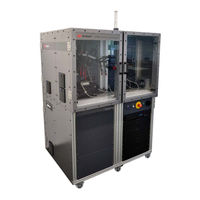
Keysight PD1550A System Installation Manual (292 pages)
Advanced Dynamic Power Device Analyzer
Brand:
Keysight
| Category:
Measuring Instruments
| Size: 8.22 MB
Table of Contents
Table of Contents
8
Site Preparation 1
14
Customer Responsibilities
15
Rack and Safety Enclosure Dimensions and Weight
15
Site Preparation
15
Static-Safe Handling Procedures
16
Power Module Test Rack and Safety Enclosure Location
17
Rack Ventilation
18
AC Power Cord
19
Connect the Rack and Safety Enclosure to AC Mains
19
Circuit Breakers
20
Connection of the PD1550A to the AC Mains
20
Mains Disconnect
20
Optional Safety Ground Connection
20
Moving the Rack and Safety Enclosure
21
Receiving the PD1550A
21
Accessories Included with the PD1550A
22
Inventory the Shipment
22
PD1550A Accessories (Not Included)
26
Optional (Not Required) PD1550A Accessories
27
Host Computer Requirements
28
What Is Not Supplied with the Rack and Safety Enclosure
28
PD1550A Documentation
29
Simplified System Diagrams
30
Tools Required for Uncrating the PD1550A Rack
32
Uncrate the PD1550A Rack and Safety Enclosure
32
Uncrate the Rack and Safety Enclosure
33
Moving the Rack and Safety Enclosure
40
Re-Crating the Rack and Safety Enclosure for Shipping
41
Accessory and Probe Installation
42
Stabilize the Rack
43
Tools Required to Install Accessories
43
Install Tower Light on Top of the Rack
44
Apply Power and Turn on the PD1500A
46
Connect Three Short BNC Cables
47
External Ground Connector
48
Rack Connections
48
USB, External LAN, and HDMI Connectors
48
LAN External, E-Stop Signal Light Connectors
49
Power in / Power out Connectors
49
Open the Side Shelf
50
Open the Drawers
51
Install Probe Holders
52
Add Ferrite Core Inductor to N2873A Probe
54
Install Coaxial Shunt Resistor
55
Install Components on PD1550A Interface Module
55
Attach 62 MM DUT Module
56
Install Gate Drive Resistor Modules on the Interface Module
59
How to Measure Gate Resistors
60
Schematic of Path for Gate Resistors
60
Install Gate Drive Resistor Modules on the Interface Module
61
Install Gate Drive Modules on the Interface Module
62
Connect Interface Module to PD1550A Test System
64
Install UDI Cables to the Gate Drive and Interface Modules
64
Connect Probes to Oscilloscope
66
Connect Oscilloscope Probes to DUT Interface Module
69
Connect Probe for High-Side DUT Measurements
71
High-Side Drain/Collector Current
71
High-Side Gate Voltage
71
Keysight Isolated Probe Unit
72
Apply Oscilloscope Probe Labels
73
Install UDI Cables
74
External Loads
75
Install Additional Test Fixture Accessories
75
How to Select the Thermistor Resistance Value
76
NTC Thermistor Connector
76
Range of External Inductors
76
Reading the Temperature(S) in the PD1000A Control Software
76
Cable Requirements for the PT1000NTC Thermistor
77
Fan out 24 VDC
77
Type K Thermocouples, CH1 and CH2
77
Method of Securing the Thermocouple to a Device
78
Preparing the Thermocouple
78
Reading the Temperature(S) in the PD1000A Control Software
79
Recommendations for Using a Thermocouple
79
Install Optional Intest Temperature Controller with Heating Plate
80
Install the Intest Control Unit in the PD1550A Rack
81
Install Optional Intest - Temptronic Thermostream Heater/Cooler System
84
Thermostream Electrical Connections to the PD1550A Rack
85
Thermostream Compressed Air Requirements
86
Turn-On and Software Installation 4
88
Double-Pulse Test System Turn-On and Turn-Off
89
Step 1: Connect LAN and Power Cable to Rack
89
Emergency off Functionality
90
Light Tower on Top of Rack
90
Turning the System off
90
Download PD1000A System Control Software
91
Install IO Libraries Suite on Host PC
91
Step 2: Install System Software on Host PC
91
Set Oscilloscope VISA Address
92
More about IP Addresses and Dot Notation
93
Set AC Line Frequency and Date/Time on the B2902A
93
Annual Characterization of the Coaxial Shunt
94
Obtain the Shunt De-Embedding File
94
Step 3: Obtain and Install Coaxial Shunt Resistor De-Embedding File
94
Install the De-Embedding Transfer File on the Oscilloscope
96
Autocal
98
PD1550A System Calibration-Autocal
98
Initiate Calibration & Compensation Procedures
100
Low Frequency Compensation for the N2873A Probe
101
Oscilloscope Probe Offset Compensation
101
Required Equipment
101
DP0001A Settings in the Oscilloscope User Interface
102
Setting the Attenuation Mode
102
Performing DC Offset and Gain Calibration
103
DP0031A Settings in the Oscilloscope User Interface
104
PD1550A System Calibration (Autocal)
105
Requirements
105
Schematic for Gate Resistor Modules
106
GS,L Output
107
Low-Side Gate Voltage Source Calibration
107
Output
107
Com,L
108
Low-Side Common Resistor Calibration -- R
108
Gon,L
109
Low-Side Gate Resistance Calibration -- R
109
Goff,L
110
Low-Side Gate Resistance Calibration -- R
110
GS,H Output
111
High-Side Gate Voltage Source Calibration
111
Output
111
Com,H
112
High-Side Common Resistor Calibration -- R
112
Gon,H
113
High-Side Gate Resistance Calibration -- R
113
Goff,H
114
High-Side Gate Resistance Calibration -- R
114
10 Calibration Complete
115
Coaxial Shunt Resistor Characterization
116
Install the De-Embedding Transfer File on the Oscilloscope
116
A Selecting Gate Drive Resistors
118
Small Gate Resistor Values
118
Large Gate Resistor Values
119
Optimal Gate Resistor Value
119
B Installing Surface-Mount Devices
124
Using a Hot Air Solder Reflow Tool
125
Using a Small-Tip Soldering Iron
125
CSMA Connector Care & Connection
128
Final Connection Using a Torque Wrench
129
Separating Connections
130
Connector Cleaning
131
Inspect and Clean Connectors
131
Simplified System Wiring D
132
PD1550A High Voltage Wiring
133
PD1550A Power Wiring
134
PD1550A Ethernet Wiring
135
PD1550A Internal UDI Wiring
136
PD1550A BNC Wiring
137
PD1550A BNC Wiring (Internal to the Rack)
137
PD1550A D-Sub Connector Wiring
138
PD1550A Connect Probes to Oscilloscope
139
Connect Probes for High-Side DUT Measurements
141
High-Side Gate Voltage
141
Site Preparation/Uncrate the Pd1550A Rack and Safety Enclosure
155
Site Preparation 1
161
Customer Responsibilities
162
Rack and Safety Enclosure Dimensions and Weight
162
Site Preparation
162
Static-Safe Handling Procedures
163
Power Module Test Rack and Safety Enclosure Location
164
Rack Ventilation
165
AC Power Cord
166
Connect the Rack and Safety Enclosure to AC Mains
166
Circuit Breakers
167
Connection of the PD1550A to the AC Mains
167
Mains Disconnect
167
Optional Safety Ground Connection
167
Moving the Rack and Safety Enclosure
168
Receiving the PD1550A
168
Accessories Included with the PD1550A
169
Inventory the Shipment
169
PD1550A Accessories (Not Included)
173
Optional (Not Required) PD1550A Accessories
174
Host Computer Requirements
175
What Is Not Supplied with the Rack and Safety Enclosure
175
PD1550A Documentation
176
Simplified System Diagrams
177
Tools Required for Uncrating the PD1550A Rack
179
Uncrate the PD1550A Rack and Safety Enclosure
179
Uncrate the Rack and Safety Enclosure
180
Moving the Rack and Safety Enclosure
187
Re-Crating the Rack and Safety Enclosure for Shipping
188
Accessory and Probe Installation
189
Stabilize the Rack
190
Tools Required to Install Accessories
190
Install Tower Light on Top of the Rack
191
Apply Power and Turn on the PD1500A
193
Connect Three Short BNC Cables
194
External Ground Connector
195
Rack Connections
195
USB, External LAN, and HDMI Connectors
195
LAN External, E-Stop Signal Light Connectors
196
Power in / Power out Connectors
196
Open the Side Shelf
197
Open the Drawers
198
Install Probe Holders
199
Add Ferrite Core Inductor to N2873A Probe
201
Install Coaxial Shunt Resistor
202
Install Components on PD1550A Interface Module
202
Attach 62 MM DUT Module
203
Install Gate Drive Resistor Modules on the Interface Module
206
How to Measure Gate Resistors
207
Schematic of Path for Gate Resistors
207
Install Gate Drive Resistor Modules on the Interface Module
208
Install Gate Drive Modules on the Interface Module
209
Connect Interface Module to PD1550A Test System
211
Install UDI Cables to the Gate Drive and Interface Modules
211
Connect Probes to Oscilloscope
213
Connect Oscilloscope Probes to DUT Interface Module
216
Connect Probe for High-Side DUT Measurements
218
High-Side Drain/Collector Current
218
High-Side Gate Voltage
218
Keysight Isolated Probe Unit
219
Apply Oscilloscope Probe Labels
220
Install UDI Cables
221
External Loads
222
Install Additional Test Fixture Accessories
222
How to Select the Thermistor Resistance Value
223
NTC Thermistor Connector
223
Range of External Inductors
223
Reading the Temperature(S) in the PD1000A Control Software
223
Cable Requirements for the PT1000NTC Thermistor
224
Fan out 24 VDC
224
Type K Thermocouples, CH1 and CH2
224
Method of Securing the Thermocouple to a Device
225
Preparing the Thermocouple
225
Reading the Temperature(S) in the PD1000A Control Software
226
Recommendations for Using a Thermocouple
226
Install Optional Intest Temperature Controller with Heating Plate
227
Install the Intest Control Unit in the PD1550A Rack
228
Install Optional Intest - Temptronic Thermostream Heater/Cooler System
231
Thermostream Electrical Connections to the PD1550A Rack
232
Thermostream Compressed Air Requirements
233
Turn-On and Software Installation 4
235
Double-Pulse Test System Turn-On and Turn-Off
236
Step 1: Connect LAN and Power Cable to Rack
236
Emergency off Functionality
237
Light Tower on Top of Rack
237
Turning the System off
237
Download PD1000A System Control Software
238
Install IO Libraries Suite on Host PC
238
Step 2: Install System Software on Host PC
238
Set Oscilloscope VISA Address
239
More about IP Addresses and Dot Notation
240
Set AC Line Frequency and Date/Time on the B2902A
240
Annual Characterization of the Coaxial Shunt
241
Obtain the Shunt De-Embedding File
241
Step 3: Obtain and Install Coaxial Shunt Resistor De-Embedding File
241
Install the De-Embedding Transfer File on the Oscilloscope
243
Autocal
245
PD1550A System Calibration-Autocal
245
Initiate Calibration & Compensation Procedures
247
Low Frequency Compensation for the N2873A Probe
248
Oscilloscope Probe Offset Compensation
248
Required Equipment
248
DP0001A Settings in the Oscilloscope User Interface
249
Setting the Attenuation Mode
249
Performing DC Offset and Gain Calibration
250
DP0031A Settings in the Oscilloscope User Interface
251
PD1550A System Calibration (Autocal)
252
Requirements
252
Schematic for Gate Resistor Modules
253
GS,L Output
254
Low-Side Gate Voltage Source Calibration
254
Output
254
Com,L
255
Low-Side Common Resistor Calibration -- R
255
Gon,L
256
Low-Side Gate Resistance Calibration -- R
256
Goff,L
257
Low-Side Common Resistor Calibration -- R
257
Low-Side Gate Resistance Calibration -- R
257
GS,H Output
258
High-Side Gate Voltage Source Calibration
258
Output
258
Com,H
259
High-Side Common Resistor Calibration -- R
259
Gon,H
260
High-Side Common Resistor Calibration -- R
260
High-Side Gate Resistance Calibration -- R
260
Goff,H
261
High-Side Gate Resistance Calibration -- R
261
10 Calibration Complete
262
Coaxial Shunt Resistor Characterization
263
Install the De-Embedding Transfer File on the Oscilloscope
263
A Selecting Gate Drive Resistors
265
Small Gate Resistor Values
265
Large Gate Resistor Values
266
Optimal Gate Resistor Value
266
B Installing Surface-Mount Devices
271
Using a Hot Air Solder Reflow Tool
272
Using a Small-Tip Soldering Iron
272
C SMA Connector Care & Connection
275
Final Connection Using a Torque Wrench
276
Separating Connections
277
Connector Cleaning
278
Inspect and Clean Connectors
278
PD1550A High Voltage Wiring
280
PD1550A Power Wiring
281
PD1550A Ethernet Wiring
282
PD1550A Internal UDI Wiring
283
PD1550A BNC Wiring
284
PD1550A D-Sub Connector Wiring
285
PD1550A Connect Probes to Oscilloscope
286
PD1550A Connect Probes to Oscilloscope
287
Connect Probes for High-Side DUT Measurements
288
High-Side Gate Voltage
288
Advertisement
Advertisement
Related Products
Keysight PD1000A
Keysight P-Series
Keysight PNA N5225A
Keysight PNA N5224A
Keysight PNA N5227A
Keysight PNA E8362C
Keysight P9371A
Keysight P9372A
Keysight P9374A
Keysight P9375A
Keysight Categories
Measuring Instruments
Test Equipment
Multimeter
Control Unit
Portable Generator
More Keysight Manuals
Login
Sign In
OR
Sign in with Facebook
Sign in with Google
Upload manual
Upload from disk
Upload from URL