Sign In
Upload
Manuals
Brands
BONFIGLIOLI Vectron Manuals
DC Drives
ACTIVE CUBE Series
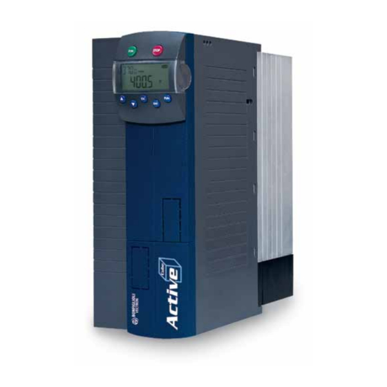
BONFIGLIOLI Vectron ACTIVE CUBE Series Manuals
Manuals and User Guides for BONFIGLIOLI Vectron ACTIVE CUBE Series. We have
2
BONFIGLIOLI Vectron ACTIVE CUBE Series manuals available for free PDF download: Manual, Applications Manual
BONFIGLIOLI Vectron ACTIVE CUBE Series Manual (200 pages)
EtherCAT Communication module CM-EtherCAT Frequency inverter 230 V / 400 V
Brand:
BONFIGLIOLI Vectron
| Category:
DC Drives
| Size: 16 MB
Table of Contents
Table of Contents
3
1 General Information about the Documentation
8
This Document
9
Warranty and Liability
9
Obligation
10
Copyright
10
Storage
10
2 General Safety Instructions and Information on Use
11
Terminology
11
Designated Use
12
Misuse
12
Explosion Protection
12
Residual Risks
12
Safety and Warning Signs at Frequency Inverter
12
Warning Information and Symbols Used in the User Manual
13
Hazard Classes
13
Hazard Symbols
13
Prohibition Signs
13
Personal Safety Equipment
13
Recycling
14
Grounding Symbol
14
ESD Symbol
14
Information Signs
14
Directives and Guidelines to be Adhered to by the Operator
15
Operator's General Plant Documentation
15
Operator's/Operating Staff's Responsibilities
15
Selection and Qualification of Staff
15
General Work Safety
15
Organizational Measures
15
General
15
Use in Combination with Third-Party Products
16
Transport and Storage
16
Handling and Installation
16
Electrical Connections
16
The Five Safety Rules
17
Safe Operation
17
Maintenance and Service/Troubleshooting
18
Final Decommissioning
18
3 Introduction
19
Supported Configurations
21
Initialization Time
22
4 First Commissioning
22
5 Installation/Disassembly of the Communication Module
23
Installation
23
Disassembly
24
6 Connector Assignment
25
7 Run-Led
26
8 Cable Lengths
26
9 Setting the Node Address
26
10 Operational Behaviour on Bus Failure
26
11 Ethercat ® Overview
27
Communication Objects
27
Application Objects
27
Function SDO
28
Error Code Table
28
PDO Function
29
Emergency Function
29
Synchronization (Distributed Clocks)
29
NMT Functions
30
NMT Statemachine
30
OS Synchronization
31
Fault Reset
32
12 Objects
33
Objects Tabular Overview
33
Communication Objects
33
Manufacturer Objects
35
Device Profile Objects
37
Communication Objects (0X1Nnn)
41
0X1000/0 Device Type
41
0X1001/0 Error Register
42
0X1008/0 Manufacturer Device Name
43
0X1009/0 Manufacturer Hardware Version
43
0X100A/0 Manufacturer Software Version
43
0X1010/N Store Parameters
43
0X1011/N Restore Default Parameters
44
0X1018/N Identity Object
44
0X1600/N, 0X1601/N, 0X1602/N, Rxpdo Mapping Parameter
45
0X1A00/N, 0X1A01/N, 0X1A02/N, Txpdo Mapping Parameter
46
Manufacturer Objects (0X2Nnn) - Parameter Access
47
Handling of Data Sets/Cyclic Writing of the Parameters
47
Handling of Index Parameters/Cyclic Writing
48
Example Writing an Index Parameter
49
Example Reading an Index Parameter
49
Manufacturer Objects (0X3000
50
0X3001/0 Digital in Actual Value
50
0X3002/0 Digital out Actual Value
50
0X3003/0 Digital out Set Values
51
0X3004/0 Boolean Mux
52
0X3005/0 Boolean Demux
53
0X3006/0 Percentage Set Value
54
0X3007/0 Percentage Actual Value Source 1
55
0X3008/0 Percentage Actual Value Source 2
55
0X3011/0 Actual Value Word 1
56
0X3012/0 Actual Value Word 2
56
0X3021/0 Actual Value Long 1
57
0X3022/0 Actual Value Long 2
57
0X3111/0 Ref. Value Word 1
58
0X3112/0 Ref. Value Word 2
58
0X3121/0 Ref. Value Long 1
59
0X3122/0 Ref. Value Long 2
59
0X5F10/N Gear Factor
60
0X5F11/N
61
0X5F15/0 in Gear Threshold
63
0X5F16/0 in Gear Time
64
0X5F17/N Position Controller
65
0X5F18/0 M/S Synchronization Offset
67
0X5Ff0/0 Active Motion Block
68
0X5Ff1/0 Motion Block to Resume
68
Device Profile Objects (0X6Nnn)
69
0X6007/0 Abort Connection Option Code
69
0X603F/0 Error Code
71
0X6040/0 Control Word
72
0X6041/0 Status Word
73
0X6042/0 Target Velocity [Rpm]
74
0X6043/0 Target Velocity Demand [Rpm]
75
0X6044/0 Control Effort
75
0X6046/N Velocity Min Max Amount
75
0X6048/N Velocity Acceleration
77
0X6049/N Velocity Deceleration
78
0X604A/N Velocity Quick Stop
79
0X6060/0 Modes of Operation
80
0X6061/0 Modes of Operation Display
81
0X6064/0 Position Actual Value
81
0X6065/0 Following Error Window
82
0X6066/0 Following Error Time out
83
0X6067/0 Position Window
84
0X6068/0 Position Window Time
85
0X606C/0 Velocity Actual Value [U/S]
85
0X606D/0 Velocity Window
86
0X606E/0 Velocity Window Time
87
0X606F/0 Velocity Threshold
88
0X6070/0 Velocity Threshold Time
89
0X6071/0 Target Torque
90
0X6077/0 Torque Actual Value
90
0X6078/0 Current Actual Value
90
0X6079/0 Dclink Circuit Voltage
91
0X607A/0 Target Position
91
0X607C/0 Home Offset
92
0X6081/0 Profile Velocity [U/S]
93
0X6083/0 Profile Acceleration
94
0X6084/0 Profile Deceleration
94
0X6085/0 Quick Stop Deceleration
95
0X6086/0 Motion Profile Type
96
0X6091/N Gear Ratio
97
0X6092/N Feed Constant
98
0X6098/0 Homing Method
99
0X6099/N Homing Speeds
101
0X609A/0 Homing Acceleration
102
0X60C1/1 Interpolation Data Record
103
0X60F4/0 Following Error Actual Value
105
0X60F8/0 Max Slippage [U/S]
106
0X60Ff/0 Target Velocity [U/S]
106
13 Motion Control Interface (MCI)
107
Parameter Dependencies in Motion Control
108
Reference System
113
Homing
114
Start Position after Homing
114
Flying Homing
114
Position Controller
114
Move Away from Hardware Limit Switches
115
Motion Control Interface for Experts
116
Motion Control Override
117
14 Inverter Control
118
Control Via Digital Inputs/Remote Digital Inputs
119
Device State Machine
121
Control Via State Machine
122
Statemachine Diagram
124
Non Motion Control Configurations
127
Behaviour in Quick Stop
127
Behaviour in Transition 5 (Disable Operation)
128
Reference Value / Actual Value
129
Example Sequence
130
Motion Control Configurations
131
Velocity Mode [Rpm]
132
Example Sequence
135
Profile Velocity Mode [U/S]
137
Example Sequence
140
Profile Position Mode
141
Example Sequence
147
Interpolated Position Mode
149
Example Sequence
153
Homing Mode
154
Example Sequence
156
Cyclic Synchronous Position Mode
157
Example Sequence
159
Cyclic Synchronous Velocity Mode
160
Example Sequence
162
Table Travel Record
163
Example Sequence
170
Move Away from Limit Switches
171
Example Sequence
174
Electronic Gear: Slave
175
Master/Slave Position Correction
182
Sequence Example
184
15 Parameter List
186
Actual Values
186
Parameter
187
16 Annex
188
Control Word/Status Word Overview
189
Control Word Overview (Without Sync Modes)
189
Status Word Overview (Without Sync Modes)
190
Control Word Overview for Sync Modes
191
Status Word Overview for Sync Modes
191
Warning Messages
192
Warning Messages Application
193
Fault Messages
194
Conversions
195
Speed [Rpm] to Frequency [Hz]
195
Frequency [Hz] to Speed [Rpm]
195
Speed in User Units [U/S] to Frequency [Hz]
195
Frequency [Hz] to Speed in User Units [U/S]
195
Speed in User Units [U/S] to Speed [Rpm]
195
Speed [Rpm] to Speed in User Units [U/S]
195
Object Support in the Software Versions and XML Files
196
Index
198
Advertisement
BONFIGLIOLI Vectron ACTIVE CUBE Series Applications Manual (176 pages)
Positioning
Brand:
BONFIGLIOLI Vectron
| Category:
Inverter
| Size: 2 MB
Table of Contents
Table of Contents
4
1 General Safety Instructions and Information on Use
7
General Information
7
Purpose of the Frequency Inverters
8
Transport and Storage
8
Handling and Installation
8
Electrical Connection
9
Information on Use
9
Maintenance and Service
9
2 System Description
10
Terminal Diagram ACTIVE Cube (ACU) Series
11
3 Commissioning of the Frequency Inverter
12
Switching on Mains Voltage
12
Commissioning of the Motor
13
Control Inputs and Outputs
14
Factory Settings of the Digital Inputs
15
Digital Inputs for Speed Sensor Inputs or for Other Functions
17
Positioning - Commissioning Procedure
18
Getting Started
20
Motor Encoder Is Position Encoder at the same Time
20
Two Different Encoders for Motor and Positioning
21
No Motor Encoder, External Encoder for Positioning
22
Consider the Operation Mode Settings for Speed Sensor Input
22
Reference System
23
Setting up a Motion Profile
26
Control Via Software
27
Write Index and Read Index for the Motion Blocks Table
28
4 Operation Modes of the Positioning
30
General Issues about Operation Modes
30
Assignment of Digital Inputs
31
Instructions on MFI1D (Multifunction Input)
32
Operation Modes for Controlling the Positioning Operation
33
Input and Output Signals
35
Homing
36
Automatic of Manual Start of Homing
36
Input and Output Signals for Homing
37
Homing Mode
39
Home Offset
40
Speed and Acceleration of Homing Operation
40
Positioning Mode
41
Motion Block Management
41
Vtable
42
Positioning Mode and Motion Block Data
43
Motion Mode
43
Motion Mode "Absolute
46
Motion Mode "Relative
46
Motion Mode "Touch Probe" (Sensor)
47
Motion Mode "Velocity
49
Combination with Electronic Gear
50
Motion Block Data
56
Target Position
56
Speed
56
Acceleration and Deceleration
57
Automatic Sequence of Motion Blocks (Next Motion Block)
57
Single Motion
64
Control of Motion
65
Selection of Motion Block Via Digital Signals (Motion Block Change-Over)
65
Motion Block Selection Via Parameter (Starting-Record Number)
67
Input and Output Signals for Motion Blocks
68
Starting, Stopping and Resuming
69
Starting and Stopping Positioning
70
Resuming Interrupted Motion Blocks
74
Digital Signals for Indication of Status of Motion Orders
75
JOG Mode
78
Fixed Speed in JOG Mode
81
Acceleration and Deceleration in JOG Mode
83
Teach-In (Saving Actual Position as Target Position)
83
Electronic Gear
87
Master Position Source
87
Gear Factor
89
Resynchronization
89
Phasing Function
89
Monitoring Functions
92
Travel Limits
92
Hardware Limit Switches
92
Hysteresis for Hardware Limit Switch
95
Fault Reaction
96
Software Limit Switches
97
Move Away from HW Limit Switches
97
Move Away from SW Limit Switches
100
Target Window
101
Contouring Error Supervision
102
Warning Mask Application
104
Speed Override
106
Position Comparator
107
Rotary Table Application
109
Position Controller
112
Store the Actual Position Value (Latching Function)
114
Wiring Example
115
5 List of Homing Modes
117
Brief Description Homing
117
Overview Table of Homing Types
119
Graphic Overview of Homing Modes
120
Terminology
121
Description of Homing Modes
122
Homing Modes with Ref. Signal
123
Homing Modes Without Reference Signal
139
Homing Modes, Only Ref. Signal and Actual Position
152
6 Output Signals and Fault Messages
153
Actual Positioning Values
153
Status Word of the Positioning
154
Status Word 411
156
Digital Positioning Output Signals
157
Logic Signal Sources for Positioning
158
Positioning Error Messages
160
Positioning Warning Status
164
Diagnosis and Fault Clearance
164
Touch Probe: Drive Is Decelerated or Stops
165
Drive Jerks/Is very Load
165
7 Parameter List
166
Actual Value Menu (VAL)
166
Parameter Menu (PARA)
166
Parameter List, Sorted by Function
170
Index
172
Advertisement
Related Products
BONFIGLIOLI Vectron ACTIVE
BONFIGLIOLI Vectron Agile
BONFIGLIOLI Vectron AEC 401-19
BONFIGLIOLI Vectron AEC 401-22
BONFIGLIOLI Vectron AEC 401-23
BONFIGLIOLI Vectron AEC 401-27
BONFIGLIOLI Vectron AEC 401-29
BONFIGLIOLI Vectron AEC 401-31
BONFIGLIOLI Vectron AEC 401-35
BONFIGLIOLI Vectron AEC 401-37
BONFIGLIOLI Vectron Categories
DC Drives
Inverter
Control Unit
More BONFIGLIOLI Vectron Manuals
Login
Sign In
OR
Sign in with Facebook
Sign in with Google
Upload manual
Upload from disk
Upload from URL