Table of Contents
Advertisement
Quick Links
Advertisement
Table of Contents

Subscribe to Our Youtube Channel
Related Manuals for Paradyne Hotwire 8300


Summary of Contents for Paradyne Hotwire 8300
- Page 1 Hotwire ® 8300 Endpoint User’s Guide Document No. 8300-A2-GB20-00 April 2003...
- Page 2 When the product is marked with the CE mark on the equipment label, a supporting Declaration of Conformity may be downloaded from the Paradyne World Wide Web site at www.paradyne.com. Select Library CE Declarations of Conformity. April 2003 Technical Manuals 8300-A2-GB20-00...
-
Page 3: Table Of Contents
Introduction ..........Features of the 8300 Endpoint....... - Page 4 Save and Restart ........April 2003 2-14 2-19 2-22 2-24 2-25 2-26 2-27 2-27 2-34 2-42 2-43 2-43 2-46 2-47 2-48 2-49 2-64 2-65 2-71 2-76 2-79 2-81 2-81 2-82 2-83 8300-A2-GB20-00...
- Page 5 Alarms ..........8300-A2-GB20-00...
- Page 6 SNMP Trap Configuration ........Generic MIB Loading Instructions ......Index April 2003 A-10 8300-A2-GB20-00...
-
Page 7: About This Guide
This guide describes the features, configuration, and use of the ® Hotwire 8300 Endpoint. It is intended for installers and operators of the product. Installation instructions for the 8300 Endpoint can be found in the Hotwire 8300 Endpoint Installation Instructions (document number 8300-A2-GN10). Document Summary Section... -
Page 8: Product-Related Documents
The following table lists the graphic conventions used throughout this guide. Convention Technical Manuals Document Title Hotwire 8300 Endpoint Installation Instructions Hotwire ATM Line Cards, Models 8335, 8355, 8365, and 8385, User's Guide Description A N o t i c e c a l l s a t t e n t i o n s t o i m p o r t a n t f e a t u r e s o r i n s t r u c t i o n s . -
Page 9: About The Hotwire 8300 Endpoint
This unit supports CES over the CBR port and the Serial port. A router or bridge using PPP/HDLC protocols connects to the 8300 Endpoint’s Serial port. The unit encapsulates the PPP data into ATM cells using Internet Engineering Task Force (IETF) RFC 1483. - Page 10 1. About the Hotwire 8300 Endpoint RIP 1 and RIP 2 allow routers to exchange routing information. The 8300 Endpoint then uses this information exchange to build routing tables for IP Packet routes. After building the routing tables, the unit periodically broadcasts the contents to neighboring routers so your network can choose the most efficient routes available.
-
Page 11: Features Of The 8300 Endpoint
WAN management performance. The 8300 Endpoint also allows firmware to be upgraded via the web from a standard browser, with password control if desired. SNMP Management With integrated SNMP in-band management, enterprise managers can now manage 8300 Endpoints and their integral CSU/DSUs as a single unit. -
Page 12: Features Summary
1. About the Hotwire 8300 Endpoint Allows for continued use of existing TDM equipment by supporting CES via AAL1. Reduces the need for costly routers with its IP Gateway feature. Offers easy installation and configuration, reducing maintenance and sparing costs. - Page 13 — Decreased installation and configuration time for service employees — Simplified troubleshooting and fault isolation of network problems — Optimal management of ATM-based services — Saves and downloads configuration files from remote server April 2003 1. About the Hotwire 8300 Endpoint...
-
Page 14: Front Panel
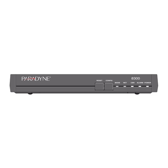
1. About the Hotwire 8300 Endpoint Front Panel The front panel of the 8300 Endpoint is shown below in Figure 1-1. Figure 1-1. The front panel’s five LED status indicators are described below: Indicator MODE C B R A L A R M... - Page 15 To initiate this function, you must press and hold the CONFIG button during a power-up sequence. The CONFIG button must be held until the MODE LED lights amber and remains illuminated for the default configuration to take effect. April 2003 1. About the Hotwire 8300 Endpoint...
-
Page 16: Rear Panel Connections
1. About the Hotwire 8300 Endpoint Rear Panel Connections The rear panel of the 8300 Endpoint has five connectors. From left to right, these are as follows: N E T W O R K Figure 1-2. Power Port P O W E R connector. -
Page 17: Supervisory Port
Serial Port The SERIAL interface port located on the 8300 Endpoint rear panel is a multi-protocol interface presented physically as a DB-25 connection. The protocols supported by this interface are RS-232, V.35, V.36, EIA-530, X.21, and RS-449. -
Page 18: Cbr Port
1. About the Hotwire 8300 Endpoint CBR Port The CBR interface port located on the 8300 Endpoint rear panel is an RJ-48C, eight-pin modular jack that can be software-selectable for T1 or E1. As a T1 port, it terminates as 100 ohms, and as an E1 port at 120 ohms. This port is used to transport TDM traffic using a T1/E1 framer to provide ATM adaptation Layer 1 with Circuit Emulation Services (AAL1-CES). -
Page 19: Web Server Interface
Web Server Interface The 8300 Endpoint has an innovative, embedded web-based user interface for remote configuration and real-time reporting via Microsoft Internet Explorer 5.0 or higher. Access to the web server interface and how the interface is used to configure the 8300 Endpoint are described in detail below. -
Page 20: Web Server Access
Any changes to the unit’s configuration MUST be followed by a Submit if there is a Submit button on the menu. If you change the Service Table, you must perform a Save and Restart. April 2003 8300-A2-GB20-00... -
Page 21: Unit Screen
Location FrameStart ID Blank Fields Time Date 8300-A2-GB20-00 Unit Screen Function Display-only field used to point an SNMP agent to this ID. Displays the amount of time the unit has been up and running. Stores the name of a point-of-contact for system failure. -
Page 22: Maintenance Reset
Saves the current configuration and restarts the unit. Serial HDLC Encapsulated T1 CBR in ATM Channels None None − None None April 2003 E1 CBR Serial CBR Channels Channels None None None None None None None − None − 3 1 to the − Figure 2-2. 8300-A2-GB20-00... -
Page 23: Save And Restart
Click the Save and Restart button on the confirmation screen to proceed with the action. To cancel, simply invoke your browser’s Back function. Interfaces The 8300 Endpoint has five available interfaces: Network, CBR, Serial, Ethernet 10/100, and Supervisory. These interfaces are described below. 8300-A2-GB20-00... -
Page 24: Network
2. Web Server Interface Network The 8300 Endpoint Network screen to the Network interface's configuration. Figure 2-4. The Network screen status and configuration parameters are described in the following paragraphs. Unit Type Selects the unit type. TU-R represents a CPE terminal unit; TU-C represents a CO terminal unit. - Page 25 Represents the status and detail status information of the span for two-wire operation. Pair-2 Mode Represents the status and detail status information of the span for four-wire operation. This mode is not supported by the 8300 Endpoint. EOC In Displays the number of messages received on the Embedded Operations Channel.
- Page 26 This screen lets you configure or change the following information about the selected configuration profile: Wire Mode Displays the type of wire interface used by the span. The 8300 Endpoint supports only the two-wire mode. Data Rate (Min) Sets the minimum attainable data rate in the span.
- Page 27 Figure Figure 2-7. 8300-A2-GB20-00 When the 8300 Endpoint is operating with Unit Type set to TU-R, it supports Annex-A or Annex-B. The configuration of the TU-C unit determines the actual transmission mode used. Annex-A must be used for U.S. and Canadian deployments.
- Page 28 15-minute performance data collection interval. If the value of LOSW in a particular 15-minute collection interval reaches/exceeds this value, a trap is generated. One trap will be sent per interval per endpoint. A value of 0 (zero) disables the trap. 2-10 Figure 2-8. Alarm Profile Details Screen April 2003 8300-A2-GB20-00...
- Page 29 Figure 2-10. Span Endpoint Details Screen Vendor ID Displays the Vendor ID as reported in an Inventory Response message. 8300-A2-GB20-00 Any changes to the above-listed parameters must be followed by a Submit for the changes to take effect. Figure 2-9.
- Page 30 TU-C, endpoint will be Customer. Wire Pair Always Wire Pair 1. Clicking on the Span Endpoint Performance/Summary button on the Span Endpoint Details screen will display the screen shown in Figure 2-11. Span Endpoint Performance/Summary Screen 2-12 Figure April 2003 2-11. 8300-A2-GB20-00...
- Page 31 Details screen will display the screen shown in Figure 2-12. This table supports maintenance operations (e.g., loopbacks) to be performed on segment endpoints. Figure 2-12. Span Endpoint Maintenance Screen The Span Endpoint Maintenance parameters are described below. 2-13 8300-A2-GB20-00 April 2003...
-
Page 32: Cbr
CBR interface’s configuration as described below. In addition, this screen provides a table that displays error status and alarm thresholds for the CBR interface. Figure 2-13. CBR Screen 2-14 (Figure 2-13). The CBR screen lets you view April 2003 8300-A2-GB20-00... - Page 33 Specifies the T1 DSX output level. Values: 0-110, 111-220, 221-330, 331-440, 441-550, 551-660, >661 ft Default: 0-110 ft 8300-A2-GB20-00 T1 ESF, T1 D4, E1 CCS, E1 CAS E1 Unframed, T1 Unframed To set unit to Signaling mode, you must first configure the following: on the CBR screen (page 2-14), configure Framing;...
- Page 34 Sets the Unavailable Seconds (UAS) threshold. A UAS is a 1-second period in which consecutive severely errored seconds cause an unavailable state. The default is 0 seconds (Disabled). Sets the Controlled Slip Seconds (CSS) threshold. The default is 0 seconds (Disabled). 2-16 April 2003 8300-A2-GB20-00...
- Page 35 Submit Clear Alarms Performance CAUTION: Figure 2-14. Performance/Summary Screen 8300-A2-GB20-00 Function Sets any values that have been changed. Resets the alarm conditions and counts to zero. Displays a Performance/Summary screen that shows a current count of the number of error events that have occurred over the past 24 hours and the past 30 days.
- Page 36 15-minute interval of the past 24 hours (Figure 2-16). Figure 2-15. Performance 24 Hour Screen Figure 2-16. Performance 30 Day Screen 2-18 Error Status and Alarm Thresholds (Figure 2-15) or during each interval (day) of the past 30 days April 2003 8300-A2-GB20-00...
-
Page 37: Serial
DSU/CSU), this parameter must be set to DTE. Values: DCE, DTE Default: DCE NOTICE: NOTICE: 8300-A2-GB20-00 (Figure 2-17) lets you view and make changes to the unit’s V.35 requires the use of an optional cable. Refer to Assignments in Appendix A, Specifications , for ordering information. - Page 38 2 4 for T1; 0 3 1 for E1 − − 2 4 for T1; 0 3 2 for E1 − − The External option is valid only in Packet mode. April 2003 it cannot be set by − 8300-A2-GB20-00...
- Page 39 Data Terminal Ready (DTR) Alarm Control parameters and view the current DTR Alarm Status. Choices for DTR Alarm Control are Enable and Disable; the default setting is Disable. Setting DTR Alarm Control to Enable allows the unit to generate an alarm 8300-A2-GB20-00 RTS/CTS Delay on page 2-21). April 2003 2.
-
Page 40: 10/100 Ethernet (Ip Service Details)
Client Identifier Displays a unique identifier for a specific IP address. Ethernet Enables or disables a remote unit’s Ethernet port. Physical Address Displays unique MAC address. 2-22 (Figure 2-18) lets you configure April 2003 8300-A2-GB20-00... - Page 41 If no IP networks are supplied, any host may access the unit. Select any Index number on the table to view the Unit Access Details (Figure 8300-A2-GB20-00 To use newly established IP parameters, you must Submit and Save Save and Restart and Restart. (See (Figure 2-19) contains no user-selectable fields or options;...
-
Page 42: Supervisory
Figure 2-21. Unit Access Details Supervisory The Supervisory screen Supervisory port interface along with other parameters as described below. The Supervisory port supports only asynchronous character formats. Figure 2-22. Supervisory Screen 2-24 (Figure 2-22) displays the current speed of the April 2003 8300-A2-GB20-00... -
Page 43: Services
Interface and Type parameters for each service. Figure 2-23. Services Screen The table in the center of the screen displays the available services listed by index number. 8300-A2-GB20-00 (Figure 2-23) provides a view of the unit’s defined services April 2003 2. -
Page 44: Service Details Screen
2-24). (In this example, the Function Sets any values that have been changed. Opens the Details screen for the Interface of the currently selected service. Opens the Details screen for the Type of the currently selected service. April 2003 8300-A2-GB20-00... -
Page 45: Ip Service Details Screen
Virtual Channel Connections on this ATM link. By default, each VCC will equally share the available bandwidth. This value should be kept as low as possible to avoid wasting bandwidth. The default value is 4. 8300-A2-GB20-00 10/100 Ethernet (IP Service Details) (Figure... - Page 46 ATM bandwidth available for AAL5 traffic. This − the current peak cell rate configured for any virtual channels − Function Sets any values that have been changed. Displays the current ATM statistics. Displays configured VCCs. Displays configured QoS profiles. April 2003 8300-A2-GB20-00...
- Page 47 Transmit section — Frames — Errored Frames — Bytes Receive — Frames — Errored Frames — Bytes Status 8300-A2-GB20-00 Figure 2-26. current number of good frames transmitted − current number of frames in error − current number of bytes sent −...
- Page 48 2-30 number of opened VCCs − number of unopened VCCs − 2-27) that summarizes the transmit and receive statistics for the 2-28) of all Virtual Channels on a specific ATM service along with April 2003 8300-A2-GB20-00...
- Page 49 If Serial PPP is selected, PPP traffic received from the Serial port will be sent over the ATM port using RFC 1483 PPPoA encapsulation. There can be only one VCI configured for Serial PPP. 8300-A2-GB20-00 (Figure 2-29). April 2003 2.
- Page 50 Serial HDLC is similar to Serial PPP except, when you select Serial HDLC, data is encapsulated transparently. Any type of HDLC traffic will be supported. Because this is not a standard encapsulation, an 8300 Endpoint must reside at each end of the connection. Even if Serial HDLC or Serial PPP encapsulation is configured, routed IP traffic received on this channel will be forwarded to the IP Gateway, if IP Gateway is configured.
- Page 51 Clicking on one of the available Traffic Description Parameters Index entries on the ATM Quality of Service Profiles screen will display a screen similar to the screen shown in parameters listed below. 8300-A2-GB20-00 Function Sets any values that have been changed. Displays the current Virtual Channel statistics.
-
Page 52: Ces Service Details Screen
Clicking on CES under the Type column of the table in the Services screen will display the CES Service Details screen shown in 2-34 Function Sets any values that have been changed. Displays configured virtual channels. Displays configured QOS profiles. Deletes this QoS profile if it is currently unused. Figure 2-32. April 2003 8300-A2-GB20-00... - Page 53 If the buffer depth falls below the predetermined lower buffer threshold, the interface clock frequency is decreased to cause the buffer to drain less quickly. Both lower and 2-35 8300-A2-GB20-00 April 2003...
- Page 54 Format Relationships Table page 2-38 for proper operation. Payload The 8300 Endpoint scrambles/descrambles cell payload bytes at the physical layer interface using an x Scrambling scrambling function on the CES Service Details Screen. Normal operation will have Payload Scrambling enabled.
- Page 55 Integration Period. When a valid cell(s) is received, this condition is cleared, and No Loss will be displayed. Configuring the 8300 Endpoint for CES involves setting parameters not only on the CES Service Details screen (page 2-35), but also on the CBR screen (page 2-14);...
- Page 56 2-33. Channel Table Details Screen April 2003 AAL1 Channel Format Rate Basic 64 k Basic 64 k Basic 64 k E1Cas 56 k/ Signaling1 Ds1EsfCas 56 k/ Signaling* Ds1SfCas 56 k/ Signaling* Basic 64 k 64 k Serial CES 8300-A2-GB20-00...
- Page 57 CES for each possible SHDSL data rate. If the required CES bandwidth exceeds the available SHDSL bandwidth, the unit will not allow you to configure the CES service. 8300-A2-GB20-00 Format Relationships Table F F (Hex) −...
- Page 58 Serial Interface, refer to the paragraphs below. 2-40 Maximum CES Channels Maximum Number of CES Channels Structured Nx64 Structured Nx64 Basic Service with E1 CAS Service (Table April 2003 Structured Nx64 with T1 CAS Service 2-1) on page 2-38 and the 8300-A2-GB20-00...
- Page 59 Serial CES Configuration The 8300 Endpoint has the capability to multiplex/demultiplex the Serial interface data stream with the CBR interface data stream. The multiplexing/demultiplexing is external to the AAL1 SAR; the user controls it by designating time slots for the CES service on the CBR or Serial port.
-
Page 60: Hdlc/Ppp Service
All channels may be allocated to either the Serial interface (Service parameter 5), or the CBR interface (Service parameter 4), or disabled (Service parameter 0). All channels must be allocated to the CBR − interface (Service parameter 4) or disabled (Service parameter 0). April 2003 8300-A2-GB20-00... -
Page 61: Applications
IP traffic is filtered. In addition, this table shows the Tx Alarm Threshold and the current Tx Alarm status (if enabled) for each rule. Figure 2-34. Service Aware Screen The Service Aware screen provides a Clear Alarms user-activated buttons: 8300-A2-GB20-00 (Figure 2-34) provides a table showing these filtered April 2003 2. - Page 62 0 (zero). (For example, 192.44.0.0 represents every computer on the Internet with an IP Address beginning with 192.44.) 2-44 (Figure 2-35), where you can establish Service To use this filter, you must specify both the Service and VPI/VCI parameters in the Rule Config screen. April 2003 8300-A2-GB20-00...
- Page 63 Figure 2-36. Traffic Meter Statistics Screen The Traffic Meter Statistics screen reports Transmit, Receive, and Performance statistics on the following parameters: Tx Frames Tx Octets Rx Frames Rx Octets 8300-A2-GB20-00 (Figure 2-36) screen displays the number of frames April 2003 2. Web Server Interface 2-45...
-
Page 64: Snmp
Address. The SNMP Details screen parameters described below. Figure 2-38. SNMP Details Screen Read Community Accepts a character string identifying the group authorized to perform read operations. The default setting is Public. 2-46 (Figure 2-38) lets you configure the SNMP April 2003 8300-A2-GB20-00... -
Page 65: Trap Log
To remove all trap information stored in memory, click the Delete All Traps button at the bottom of the screen (not shown in the figure below). Figure 2-39. Trap Log Screen 8300-A2-GB20-00 April 2003 2. Web Server Interface... -
Page 66: Top Talkers
(via the ipadv2.mib). 2-48 While you may request any number, the unit is internally limited to a maximum of 20. April 2003 8300-A2-GB20-00... -
Page 67: Ip Gateway
While RIP is ideal for small- to medium-sized networks, OSPF is more suitable for complex networks with a large number of routers. OSPF provides equal cost multipath routing where packets to a single destination can be sent via more than one interface simultaneously. 8300-A2-GB20-00 April 2003 2. Web Server Interface 2-49... - Page 68 OSPF Router ID This 32-bit number assigned to each router running the OSPF protocol uniquely identifies the router within an autonomous system. Each router requires a unique router ID. Default is the LAN IP Address of the unit. 2-50 April 2003 8300-A2-GB20-00...
- Page 69 To establish a new circuit or to change the parameters of an existing circuit, enter the desired values in the available parameter fields and press the Submit button. NOTICE: 8300-A2-GB20-00 Function Displays static routes and dynamic routes information. Displays static ARP information.
- Page 70 Indicates whether or not RIP is enabled on this circuit. Values:Disable, Listen and Talk, Talk Only, Listen Only Default:Listen and Talk Multicast Status Indicates whether or not Multicast is enabled on this circuit. Values: Enable, Disable Default: Enable 2-52 April 2003 8300-A2-GB20-00...
- Page 71 This 8-bit unsigned integer ranges from 1 to 255 and assigns priority to one of two routers attached to the same network; without an assigned priority, both routers Priority attempt to become the designated router. Values: 1 Default: 1 8300-A2-GB20-00 3 600 − 3 600 − 2 55 −...
- Page 72 VPI/VCI number. For example, VPI 0/VCI 32 will have P0-C32 for an endpoint name. The pull-down menu will display a list of 2-54 6 5535 − 6 5535 − Function Sets any values that have been changed. Returns you to the previous screen. April 2003 8300-A2-GB20-00...
- Page 73 NOTICE: Figure 2-45. Route Details Screen Endpoint Endpoint name (or interface) through which to send the IP packet to reach the Target IP Address. 8300-A2-GB20-00 Function Displays routes learned via RIP or OSPF. Adds a new static route. (Figure 2-45) by clicking on the appropriate A Submit on this screen will activate a newly created route.
- Page 74 10/100 Ethernet screen, it becomes the default route, and no WAN default route can be configured on a Static Route. 6 5535 − Function Sets any values that have been changed. Returns you to the previous screen. Deletes the route currently displayed. April 2003 8300-A2-GB20-00...
- Page 75 ARP entry is always associated with a circuit. The static ARP table is useful when a Host does not respond to an ARP request. Access this menu by selecting Static ARP Table from the RIP Parameters screen on the IP Gateway menu. 2-57 8300-A2-GB20-00 April 2003...
- Page 76 Endpoint name (or Interface) through which to send the IP packet to reach the defined IP Address. Currently, this is always the LAN. 2-58 Function Displays details of ARP tables. Displays the dynamically learned MAC <-> IP Address. Adds a new static ARP. (Figure 2-48) by clicking on the appropriate April 2003 8300-A2-GB20-00...
- Page 77 The Trusted Neighbor Table screen provides an Add New user-activated button that allows you to specify a new Trusted Neighbor. To see details regarding the Trusted Neighbor feature screen. 8300-A2-GB20-00 2 55.255.255.255 − Function Sets any values that have been changed.
- Page 78 Displays the Address Summary of the defined Area. Mask Summary Displays the Mask Summary of the defined Area. Advertise Displays whether advertising is enabled or disabled for this Area. The Add New button on this screen allows you to define a new Area. 2-60 April 2003 8300-A2-GB20-00...
- Page 79 When summarizing the routes in an area to inform other areas, all routes falling within the configured range are described by a single LSA, thus decreasing the size of the LSA database. Values: 0.0.0.0 Default: 0.0.0.0 8300-A2-GB20-00 (Figure 2-52) by clicking on a specific Index number on the 2 55.255.255.255 −...
- Page 80 Access this screen by selecting the Virtual Link Table from the OSPF Parameters table on the IP Gateway screen. 2-62 2 55.255.255.255 − Function Sets any values that have been changed. Returns you to the previous screen. Deletes the currently defined Area. Figure 2-53). To establish or maintain the April 2003 8300-A2-GB20-00...
- Page 81 The Virtual Link Details screen provides the following user-activated buttons: Button Submit Virtual Link Table Delete Virtual Link 8300-A2-GB20-00 (Figure 2-54) by clicking on an Index number on the Virtual Function Sets any values that have been changed. Returns you to the previous screen.
-
Page 82: Originate Ping
2. Web Server Interface Originate Ping The 8300 Endpoint Originate Ping companies determine if a network is properly configured and also helps them maintain SLAs. Figure 2-55. Originate Ping Screen Destination IP Destination IP Address of sent Ping request messages. -
Page 83: Network Address Translation (Nat)
255.255.255.0). Each private IP Address on the Local side is mapped to a Class C public address on the Global side. In other words, if there are 30 hosts on the 8300-A2-GB20-00 Function Sets any values that have been changed. - Page 84 TCP Sequence The maximum time (in seconds) NAT will use resources when managing TCP Packet Sequencing. Delta Timer Values: 0 Default: 180 2-66 6 5535 − 6 5535 − 6 5535 − 6 5535 − 6 5535 − April 2003 8300-A2-GB20-00...
- Page 85 The Static TCP Translation Table screen provides the following user-activated buttons: B u t t o n N A T D e t a i l s A d d N e w 8300-A2-GB20-00 6 5535 − 6 5535 −...
- Page 86 The Static UDP Translation Table screen provides the following user-activated buttons: Button NAT Details Add New 2-68 (Figure 2-58), which is accessed by selecting the (Figure 2-59) allows static mapping of Function Returns the user to the previous screen. Lets the user add an additional address. April 2003 8300-A2-GB20-00...
- Page 87 Disable, no packet with a destination address different from the global/Internet address will be processed. Setting this parameter to Disable will override an Enable parameter set under Filter Non Local Address on the NAT Details menu. 2-69 8300-A2-GB20-00 April 2003...
- Page 88 Returns the user to the NAT Details screen. Returns the user to the NAT Port Table screen. Deletes the specified NAT Port. Displays the NAT Port Status Table screen. (Figure 2-63) displays for each port the processed April 2003 8300-A2-GB20-00...
-
Page 89: Dynamic Host Configuration Protocol (Dhcp)
Figure 2-64. DHCP Server Details Screen Enable Enables or disables the DHCP Server. Default is Enable. 8300-A2-GB20-00 You must Save and Restart for any changes in DHCP configuration parameters to take effect. (Figure 2-64) lets you configure the parameters April 2003 2. - Page 90 Sets any values that have been changed. Lists Host names (DHCP server identification). Creates a list of static IP Addresses associated with MAC Addresses. Defines the addresses available for DHCP clients. (Figure (Figure 2-66) accessed by clicking on an Index April 2003 2-65), which 8300-A2-GB20-00...
- Page 91 Mask Mask associated with the IP Address shown on the screen. Host Name Name given to the DHCP client. 8300-A2-GB20-00 Function Adds a new Server name. You must Save and Restart for the new Server name to become active.
- Page 92 Exclude Start Beginning of excluded range. Exclude End End of excluded range. 2-74 Function Lets the user add an additional Static Entry. (Figure 2-69) displays the pool of addresses (Figure 2-70) accessed by clicking on an Index number. April 2003 8300-A2-GB20-00...
- Page 93 IP Address given to this DHCP client if that client has the MAC Address defined on this screen. Status Provides IP Address Status. 8300-A2-GB20-00 Function Lets the user add an additional IP Address. (Figure 2-71) displays a list of all current April 2003 2.
-
Page 94: Bridge
Values: Any valid Group Multicast MAC Address Default: 0180C2000000 Bridge ID Consists of a bridge priority and its own MAC Address. Values: 1 Default: 2 2-76 Figure 2-72 lets you access and configure the 6 5535 − April 2003 8300-A2-GB20-00... - Page 95 Bridge Port Details screen. Clicking on a number in the Index column of the Bridge Port Table will bring up the Bridge Port Details screen, which displays, and, in some cases, lets you change, the parameters described below. 8300-A2-GB20-00 6 5535 s −...
- Page 96 Lookup Table. Forwarding means the port participates fully in data transfer and the frames received are used to update the Lookup Table. Designated Root MAC Address of the designated root of the spanning-tree topology. 2-78 April 2003 8300-A2-GB20-00...
-
Page 97: Simple Mail Transfer Protocol (Smtp)
Use the SMTP Details Screen (Figure 2-76.) to configure the SMTP function of the 8300 Endpoint. SMTP is used to forward notification of events to a user-definable list of up to five recipients. The event notification is sent as an e-mail in the following format: From: sender@senderdomain.com... - Page 98 Name of domain where the device resides. Mail From E-mail address of the device (such as 8300@mainoffice.companyname.com). While the device will not be able to retrieve e-mail from a service, the mail needs to have the From address filled in.
-
Page 99: Utilities
Then click on HTTP Software Install. NOTICE: Figure 2-77. Upload/Save Screen 8300-A2-GB20-00 Make sure you allow sufficient time for the installation to occur. Canceling the installation before it has completed will result in the new software NOT being installed into the unit. -
Page 100: Password
Save the configuration setup of a unit Restore a saved configuration setup to a unit To transfer a file to or from a TFTP server from an 8300 Endpoint, you must indicate the TFTP server’s IP address, the file name, and then perform a Get operation to receive a file from the server, or a Put operation to send a file to the server. -
Page 101: Log Out
You will be automatically logged out of the system 1 hour after you log on using a password to gain access; after this, you will be required to enter the password to gain write access. 8300-A2-GB20-00 Remember that passwords are case-sensitive. When logging on, password must be entered exactly as it was programmed. - Page 102 2. Web Server Interface 2-84 April 2003 8300-A2-GB20-00...
-
Page 103: Vt100 Interface
Introduction This chapter describes the menus and options associated with the 8300 Endpoint’s VT100 interface. You can access the VT100 interface locally via the Supervisory port or remotely through a Telnet session. To access the VT100 screens locally, verify the Supervisory type is tty and the Supervisory port speed matches the terminal emulation program that’s being... -
Page 104: Cursor Controls
Hyperterm and are unable to use your arrow keys, access the pull-down menu under Terminal, click on Preferences, and be sure the VT100 Arrows box is checked. Alternative Command Ctrl+S Ctrl+D Ctrl+E Ctrl+X Ctrl+H Ctrl+Z April 2003 8300-A2-GB20-00... -
Page 105: Menu Structure
When you exit any menu other than the Main menu, you will be returned to the previous screen. Figure 3-2. CAUTION: 8300-A2-GB20-00 The data on VT100 screens is automatically refreshed every 5 seconds. You may also press Ctrl+U to redisplay the screen. Figure... -
Page 106: System Screen
Lets you modify your Admin or Read-only password by typing in a new password. Acceptable characters for use in a password are digits 0–9 and letters A–Z and a–z, for a total of 62 distinct characters. April 2003 (Figure 3-3). This 8300-A2-GB20-00... -
Page 107: Maintenance Reset
CBR port to run E1, but allocates Channels 1 Serial port. Selecting the Maintenance Reset field will display a selection screen where you can toggle (using the spacebar) among available configurations as shown in Figure 3-4. Figure 3-4. 8300-A2-GB20-00 Serial HDLC Encapsulated T1 CBR in ATM Channels None None −... -
Page 108: Save And Restart
Performing a Maintenance Reset or a Save and Restart will terminate communications with the unit. Refresh (by pressing Ctrl+U) after approximately 10 seconds to restore communications. Confirmation Screen (Figure 3-6), the 8300 Endpoint has five Interfaces Screen April 2003 8300-A2-GB20-00... -
Page 109: Network
U.S. and Canadian deployments. Expected Provisions the number of repeaters in the selected span. Repeaters Values: 0 Default: 0 (zero) 8300-A2-GB20-00 (Figure 3-7) lets you view and make changes to the Network Network Screen − April 2003 3. VT100 Interface... - Page 110 Represents the status and details status of the span for two-wire operation. Pair 2 Mode Represents the status and details status of the span for four-wire operation. This mode is not supported by the 8300 Endpoint. EOC In Displays the number of messages received on the Embedded Operations Channel.
- Page 111 Select the particular profile for which you want to see details by selecting from the <Configuration Name> on the Configuration Profile screen and then pressing the Enter key. The Configuration Details screen (Figure 3-9) supports the overall configuration of the spans. 8300-A2-GB20-00 April 2003...
- Page 112 A 32-character string that identifies a Profile Name in the Span Profile table. Each entry represents the complete span in an ATM line. Wire Mode Displays the type of wire interface used by the span). The 8300 Endpoint supports only the two-wire mode. Data Rate (Min) Sets the minimum attainable data rate in the span.
- Page 113 Esc key. Alarm Profiles Screen Selecting the Alarm Profiles prompt on the 8300 Endpoint’s Network Config screen will display the screen shown in Figure 3-10. Alarm Profiles Screen The Alarm Profiles screen displays the current values of SHDSL alarm thresholds.
- Page 114 Sets the threshold for the number of Severely Errored Seconds within any given 15-minute performance data collection interval. If the value of SES in a particular 3-12 Figure 3-11. The table on this screen lets you configure April 2003 8300-A2-GB20-00...
- Page 115 15-minute collection interval reaches/exceeds this value, a trap is generated. One trap will be sent per interval per endpoint. A value of 0 (zero) disables the trap. Span Endpoints Screen Selecting the Span Endpoints prompt on the 8300 Endpoint Network screen will display the screen shown in Figure 3-12.
- Page 116 Transmission mode capability of the SHDSL unit. Capability Endpoint Side Defines which direction the SHDSL port is pointing. Normal operation will use the TU-R configuration, and the endpoint will be Network. When unit type is TU-C, endpoint will be Customer. 3-14 April 2003 8300-A2-GB20-00...
- Page 117 Set this object to restart to initiate a restart. A restart will occur after approximately 5 seconds. Values: Ready, Restart Default: Ready Selecting the Performance prompt on the Span Endpoint Details screen will display the screen shown in 8300-A2-GB20-00 Figure 3-14. This table supports maintenance Figure 3-15. April 2003 3.
- Page 118 There no defects on the line. Indicates that the SNR margin has dropped below the alarm threshold. Indicates that the loop attenuation has exceeded the alarm − Indicates an LOSW alarm. − A loopback is currently active at this Segment Endpoint. − April 2003 8300-A2-GB20-00...
-
Page 119: Cbr
T1/E1 Framing Selects the framing for the network side of the DSU/CSU. Values: T1 ESF, T1 D4, E1 CCS, E1 CAS Default: E1 CCS 8300-A2-GB20-00 (Figure 3-16) lets you view and make changes to the CBR E1 Unframed, T1 Unframed April 2003 3. - Page 120 B8ZS. 7 .5, 1 5.0, 2 2.5 dB − − − 1 10, 111 2 20, 221 3 30, 331 4 40, 441 − − − − April 2003 5 50, 551 6 60, >661 ft − − 8300-A2-GB20-00...
- Page 121 Sets the Controlled Slip Seconds (CSS) threshold. The default is 0 seconds (Disabled). BPVS Sets the Bipolar Violation Errored Seconds (BPVS) threshold. A BPVS is a 1-second period in which at least one bipolar violation occurred. The default is 0 seconds (Disabled). 8300-A2-GB20-00 April 2003 3. VT100 Interface 3-19...
- Page 122 24 hours and the past 30 days. Performance data will be lost upon power cycle or after performing a Maintenance Reset/Restart. (Figure 3-17), which provides a summary of the error Error Status and Alarm Thresholds Table April 2003 8300-A2-GB20-00...
- Page 123 Select the Performance 30 Day prompt on the above screen to see a detailed summary of the error events that have occurred during each interval of the past 30 days (see Figure 3-19, CBR T1 Performance 30 Day Summary Screen). 3-21 8300-A2-GB20-00 April 2003...
-
Page 124: Serial
Serial parameter, simply set the parameter to the desired selection and press the Esc key. 3-22 Any changes to settings in the channel map require a Save and Restart for them to take effect. (Figure 3-21) lets you view and make changes to the unit’s April 2003 8300-A2-GB20-00... - Page 125 Selects whether the DTE channel assignment is made as a Contiguous group or as Alternate channels. Selecting Alternate ensures ones density. Because the unit allows individual channels to be configured for a service, a value of Arbitrary will 8300-A2-GB20-00 V.35 requires the use of an optional cable. Refer to Assignments in Appendix A, Specifications for ordering information.
- Page 126 2 4 for T1; 0 3 1 for E1 − − 2 4 for T1; 0 3 2 for E1 − − The External option is valid only in Packet mode. April 2003 it cannot be set by − 8300-A2-GB20-00...
- Page 127 Data Set Ready can be set to Forced True, Forced False, or Internal. The Internal option sets DSR On if the port is enabled and Off if the port is disabled. Values: Forced True, Forced False, Internal Default: Forced True 8300-A2-GB20-00 April 2003 3. VT100 Interface 3-25...
-
Page 128: 10/100 Ethernet (Ip Details)
3-22) that lets you view and/or modify the IP parameters Always verify that a DHCP server is available on the network before enabling DHCP Client. If, on power-up, a DHCP server is not found, a 60-second timeout will occur. April 2003 8300-A2-GB20-00... -
Page 129: Supervisory
Supervisory The Supervisory screen Supervisory port interface along with other parameters as described below. The Supervisory port supports only asynchronous character formats. 8300-A2-GB20-00 If you manually change the IP Address, you must Save and Restart. Save and Restart (See on page 3-6.) - Page 130 Enables the Supervisory port to send out diagnostic messages upon power-up. Messages Values: Enable, Disable Default: Enable Current Pin Status The Current Pin Status, which shows the state of the RS-232 pins, is also displayed on the Supervisory interface screen. 3-28 April 2003 8300-A2-GB20-00...
-
Page 131: Services
Selecting a number from the <Index> column will display a Service Details screen such as the one shown below type is ATM.) 8300-A2-GB20-00 (Figure 3-26) provides a view of the unit’s defined Any changes to settings in the Service Table require a Save and Restart for them to take effect. -
Page 132: Ip Service Details Screen
3-30 (Figure 3-22), accessed by selecting IP from the To use newly established IP parameters, you must Save and Restart. (See Save and Restart on page 3-6.) (Figure April 2003 3-28) by selecting the ATM link 8300-A2-GB20-00... - Page 133 The Status table provides the following status information on the circuits: QoS 0 PCR using default QoS profile. Operation Status - the current operational status for the ATM interface. 8300-A2-GB20-00 The current over-subscription factor for this ATM − CBR connections cannot be oversubscribed Also, if CES is in use...
- Page 134 − the current line bandwidth on the ATM Network interface − the current ATM bandwidth available for AAL5 traffic. This − Function Displays the current ATM statistics. Displays configured VCCs. Displays configured QoS profiles. Figure 3-29. April 2003 8300-A2-GB20-00...
- Page 135 Values: Up, Down, Testing Oper Status Current Operation Status. Values: Up, Down, Testing Last Change Time and date of the Last Change. 8300-A2-GB20-00 current number of good frames transmitted/received − current number of bytes transmitted/received − current number of frames transmitted/received in error −...
- Page 136 Serial HDLC is similar to Serial PPP except, when you select Serial HDLC, data is encapsulated transparently. Any type of HDLC traffic will be supported. Because this is not a standard encapsulation, an 8300 Endpoint must reside at each end of the connection. Even if Serial HDLC or Serial PPP encapsulation is configured, routed IP traffic received on this channel will be forwarded to the IP Gateway, if IP Gateway is configured.
- Page 137 Figure 3-32. Quality of Service Profile Screen The table displayed on this screen contains information on ATM traffic descriptor type and the associated parameters. 8300-A2-GB20-00 Virtual Channel Details Screen Function Displays the current Virtual Channel statistics. Displays configured QOS profiles.
- Page 138 Sustainable cell rate in cells per second to use for all channels using this QOS profile. Applicable to VBR only. Param 3 (MBS) Maximum burst size to use for all channels using this QOS profile. Applicable to VBR only. Row Status Current status of the profile. 3-36 Figure April 2003 3-33. Use this 8300-A2-GB20-00...
-
Page 139: Ces Service Details Screen
Both lower and upper threshold levels are used in conjunction with Cell Delay Variation to provide hysteresis around threshold levels. Values: Synchronous, Adaptive Default: Synchronous 8300-A2-GB20-00 Figure 3-34. April 2003 3. VT100 Interface... - Page 140 Specifies AAL1 format be set in accordance with the table on page 3-39 for proper operation. Payload The 8300 Endpoint scrambles/descrambles cell payload bytes at the physical layer interface using an x Scrambling scrambling function on the CES Service Details Screen. Normal operation will have Payload Scrambling enabled.
- Page 141 Displays Loss when cells are continuously lost during the specified Cell Loss Integration Period. When a valid cell(s) is received, this condition is cleared, and No Loss will be displayed. Configuring the 8300 Endpoint for CES involves setting parameters not only on the CES Service Details screen (Figure 3-16);...
- Page 142 ATM cells, only the channels with a non-zero Service parameter will be assigned data from the ATM cells. The non-active channels with a Service parameter of 0 will be filled with an idle pattern (0xFF). April 2003 (Table 3-1) on 8300-A2-GB20-00...
- Page 143 2176 2240 2304 2312* T his rate is proprietary to the GlobeSpan chipset and is required for unstructured E1 CES service. 8300-A2-GB20-00 Maximum CES Channels Maximum Number of CES Channels Structured Nx64 Structured Nx64 Basic Service with E1 CAS Service April 2003 3.
- Page 144 Serial Interface, refer to the paragraphs below. Serial CES Configuration The 8300 Endpoint has the capability to multiplex/demultiplex the Serial interface data stream with the CBR interface data stream. The multiplexing/demultiplexing is external to the AAL1 SAR; the user controls it by designating time slots for the CES service on the CBR or Serial port.
-
Page 145: Hdlc/Ppp Service
1.544 MHz clock rate. However, you may use a Basic T1 CES service and allocate all 24 channels to the Serial interface CES service resulting in a 1.536 MHz clock rate. HDLC/PPP Service This service has no configurable parameters. 8300-A2-GB20-00 Available CBR Interface Channel Range... -
Page 146: Applications
3. VT100 Interface Applications Select Applications in the Main Menu screen to display the various 8300 Endpoint applications Layer 3 and above that do not map to a specific service or interface. Figure 3-36. Applications Screen Service Aware The Service Aware function recognizes IP traffic on the WAN and counts the number of frames and bytes passed for a specific service based on filters by VPI/VCI, by IP Address, and by IP Port. - Page 147 The paragraphs below describe the rule configuration parameters and their options. Service Selects the service to which the rule applies. Select from a pull-down menu that lists available services. Selects the VPI to which the rule applies. 3-45 8300-A2-GB20-00 April 2003...
- Page 148 ATM links). In addition, this screen provides data rate performance information for the period of time specified in the <Period> field (see below). 3-46 To use this filter, you must specify both the Service and DLCI parameters in the rule configuration. April 2003 8300-A2-GB20-00...
-
Page 149: Trap Log
The table shown in this screen lists each trap by its Index number, and displays the type of error captured by the trap (Trap Number) and the date and time that the trap was stored (Time Stamp). 8300-A2-GB20-00 April 2003 3. VT100 Interface... -
Page 150: Ip Gateway
Figure 3-40. Trap Log Screen IP Gateway The IP Gateway is a feature of the 8300 Endpoint that allows routing of IP packets from one network to another using static routes configuration and/or dynamic routing. The IP Gateway uses Routing Information Protocol (RIP) 1 or RIP 2 or Open Shortest Path First (OSPF) routing. -
Page 151: Ospf Parameters
This 32-bit number assigned to each router running the OSPF protocol uniquely identifies the router within an Autonomous System. Each router requires a unique router ID. Default is the LAN IP Address of the unit. 8300-A2-GB20-00 April 2003 3. VT100 Interface... - Page 152 Table menu.The screen’s parameters are described in the paragraphs that follow. 3-50 Function Displays static and dynamic route information. Displays static ARP information. Displays trusted neighbors information. Displays area information. Displays virtual link information. Provides user access to circuit-related information/operation. April 2003 8300-A2-GB20-00...
- Page 153 Multicast Status Indicates whether or not Multicast is enabled on this circuit. Values: Enable, Disable Default: Enable OSPF Status Indicates whether or not OSPF is enabled on this circuit. Values: Enable, Disable Default: Enable 8300-A2-GB20-00 April 2003 3. VT100 Interface 3-51...
- Page 154 OSPF header. If the 64-bit (8 character) password does not correspond, the packet is thrown away. Values: 64 bits (8 characters) Default: 8 spaces (no authentication) 3-52 3 600 − 3 600 − 2 55 − 6 5535 − 6 5535 − April 2003 8300-A2-GB20-00...
- Page 155 Target IP Address Target IP Mask Next Hop Cost Rte Stat 8300-A2-GB20-00 Description Endpoint name (or interface) through which to send the IP packet to reach the Target IP Address. Represents the target network that you want this router to reach.
- Page 156 (Figure 3-45) displays the details associated with a specific route. 2 55.255.255.255 − 2 55.255.255.255 − Setting the Target IP Address and Target IP Mask to 0.0.0.0. defines THE default route for this unit. 6 5535 − April 2003 8300-A2-GB20-00...
- Page 157 ARP is deliberately disabled (for security). In these cases, instead of using ARP to dynamically update the router internal MAC <-> IP Address Table, this menu can force an entry into that table. This entry never times out. 8300-A2-GB20-00 (Figure 3-46) by selecting the Static Route Table on the IP Description Network to be reached.
- Page 158 IP Address. Currently, this is always the LAN. The IP Address of the unit for which you want to define the MAC Address. The MAC Address of the host to be reached. Displays whether this static ARP is enabled or disabled. April 2003 8300-A2-GB20-00...
- Page 159 The MAC Address of the Host to be reached. Values: A 6-byte value Default: 00-00-00-00-00-00 ARP Status Displays whether this static ARP is enabled or disabled. Values: Enable, Disable Default: Enable 8300-A2-GB20-00 2 55.255.255.255 − April 2003 3. VT100 Interface 3-57...
- Page 160 An Area allows growth and makes the networks at a site easier to manage. An area is self-contained; knowledge of an area’s topology remains hidden from other areas. Thus, multiple groups within a given site retain the ability to change their internal network topology independently. Figure 3-50. Area Table Screen 3-58 April 2003 8300-A2-GB20-00...
- Page 161 Default: Enable Auth Type Indicates type of Authentication. Values: Simple, None Default: None 8300-A2-GB20-00 Description Displays the ID of the Area (represented by an IP Address). Displays whether the defined area is enabled or disabled. Indicates Area validation. Displays whether or not the defined area is a Stub Area.
- Page 162 The virtual link must be configured in both of the area border routers. A virtual link is defined by the following two parameters: The Router ID of the virtual link’s other endpoint The non-backbone area the virtual link goes through. 3-60 2 55.255.255.255 − 2 55.255.255.255 − April 2003 8300-A2-GB20-00...
- Page 163 V i r t u a l L i n k D e t a i l s S c r e e n This screen displays the details associated with the specific Virtual Link. Figure 3-53. Virtual Link Details Screen 8300-A2-GB20-00 Description Enables the definition of a virtual link.
-
Page 164: Network Address Translation (Nat)
Global IP Address used in NAPT mode. Must be a valid Class C address. Default is LAN IP Address. 3-62 You must Save and Restart for any changes in NAT configuration parameters to take effect. (Figure 3-54) lets the user configure the NAT global April 2003 8300-A2-GB20-00... - Page 165 TCP. Values: 0 Default: 120 TCP Sequence The maximum time (in seconds) NAT will use resources when managing TCP Delta Timer Packet Sequencing. Values: 0 Default: 180 8300-A2-GB20-00 6 5535 − 6 5535 − 6 5535 − 6 5535 −...
- Page 166 Allows static mapping of global TCP Server ports to a local host IP Address/port combination. Defines NAT global/Internet and local/corporate ports. Allows static mapping of global UDP Server ports to a local host IP Address/port combination. (Figure 3-55) allows static mapping of global April 2003 8300-A2-GB20-00...
- Page 167 3-58. Access the NAT Ports Details screen by selecting the <Ndx> number of the desired port on the NAT Ports screen. Figure 3-57. NAT Ports Screen Enable Enables or disables the NAT port. Default is Enable. 3-65 8300-A2-GB20-00 April 2003...
- Page 168 The Add New prompt lets the user add additional ports. Figure 3-58. NAT Port Details Screen The NAT Port Details screen provides the following user-activated prompts: Prompt Delete Status 3-66 Function Deletes the specified NAT Port. Displays the NAT Port Status screen (Figure 3-59.). April 2003 8300-A2-GB20-00...
- Page 169 UDP Server ports to a local host IP Address/port combination. The parameters described below enable access to UDP Servers on the private/corporate network behind the NAT. The parameters may be used only when in NAPT mode. Figure 3-60. Static UDP Translation Table Screen 3-67 8300-A2-GB20-00 April 2003...
-
Page 170: Bridge
This greatly reduces the number of broadcasted packets, thus saving valuable bandwidth. The Bridge Details screen shown in parameters described below. 3-68 (Figure 3-61), which is accessed by selecting the appropriate Figure 3-62 lets you access and configure the April 2003 8300-A2-GB20-00... - Page 171 Values: 1 Default: 60 s Forward Delay Specifies the length of time to delay creation of a temporary loop in the network. Values: 1 Default: 5 s 8300-A2-GB20-00 6 5535 − 6 5535 s − 6 5535 s −...
- Page 172 Figure 3-63. Bridge Port Table Figure 3-64. Bridge Port Details Enable Enables or disables Bridging on this port. Endpoint Endpoint name. 3-70 6 5535 s − (Figure 3-64), which displays and in some April 2003 8300-A2-GB20-00...
- Page 173 Number of times this port has changed from any other state to a Forwarding state. Transmissions Input Frame Number of frames received. Output Frame Number of frames transmitted. Input Discards Number of frames discarded. 8300-A2-GB20-00 April 2003 3. VT100 Interface 3-71...
-
Page 174: Tftp Configuration
A Trivial File Transfer Protocol (TFTP) service on a server can provide remote file access to the 8300 Endpoint to Update the firmware on an 8300 Endpoint Save the configuration setup of a unit Restore a saved configuration setup to a unit To transfer a file to or from a TFTP server from a unit, you must indicate the TFTP server’s IP address and file name, and then perform a Get operation to receive a... -
Page 175: Snmp
The default setting is Public. 8300-A2-GB20-00 Function Initiates a transfer from a server to the 8300 Endpoint. Initiates a transfer from the 8300 Endpoint to a server. Aborts the transfer. Before performing the Get or Put operation, verify that the server IP address and filename have the correct values. -
Page 176: Top Talkers
Duration value is copied over to the Time Remaining field. 3-74 While you may request any number, the unit is internally limited to a maximum report size of 20. April 2003 (Figure 3-67), which is used 8300-A2-GB20-00... -
Page 177: Originate Ping
Tx octets that have been passed across it. In addition, the Timestamp field indicates the time at which a packet was examined for the specified IP Address. Originate Ping The 8300 Endpoint Originate Ping companies determine if a network is properly configured and also helps them maintain SLAs. -
Page 178: Dynamic Host Configuration Protocol (Dhcp)
You must Save and Restart for any changes in DHCP configuration parameters to take effect. Always verify that a DHCP server is available on the network before enabling DHCP Client. If, on power-up, a DHCP server is not found, a 60-second timeout will occur. April 2003 8300-A2-GB20-00... - Page 179 Domain Name Domain name to be used by all DHCP clients. Default is user’s server. Router IP Addr IP Address that all clients use for Gateway or Router. Default is 0.0.0.0. 8300-A2-GB20-00 (Figure 3-69) lets you configure the parameters April 2003 3.
- Page 180 Creates a list of static IP Addresses associated with MAC Addresses. Defines the addresses available for DHCP clients. Displays DHCP Server statistics. You must Save and Restart for the new Server name to become active. April 2003 (Figure 3-70), which identifies 8300-A2-GB20-00...
- Page 181 I P A d d r e s s L i s t S c r e e n The IP Address List screen for DHCP clients. These parameters are configured on the IP Address List Details screen accessed by selecting an Index number. 8300-A2-GB20-00 (Figure 3-71) lists static IP Addresses associated with (Figure...
- Page 182 I P A d d r e s s S t a t u s S c r e e n The IP Address Status screen clients. Figure 3-73. IP Address Status Screen 3-80 (Figure 3-73) displays a list of all current DHCP April 2003 8300-A2-GB20-00...
-
Page 183: Simple Mail Transfer Protocol (Smtp)
Simple Mail Transfer Protocol (SMTP) Use the SMTP Details Screen 8300 Endpoint. SMTP is used to forward notification of events to a user-definable list of up to five recipients. The even notification is sent as an e-mail in the following format: From: sender@senderdomain.com... - Page 184 3. VT100 Interface Mail From E-mail address of the device (such as 8300@mainoffice.companyname.com). While the device will not be able to retrieve e-mail from a service, the mail needs to have the From address filled in. NOTICE: Recipient 1...5 E-mail addresses of recipients of event notifications (such as networksupport@companyname.com).
-
Page 185: Network Interface - Shdsl Port
CBR Interface Timing Source: AAL1 Encapsulation: Partial Cell Fill: Selectable Receive Cell Delay (CDV): 100 (1 ms) default 8300-A2-GB20-00 200 kbps to 2.320 Mbps ATM Transport (G.991.2 E9) Trellis Coded Pulse Amplitude Modulation RJ49C 8-pin modular jack AAL1 and AAL5... -
Page 186: Serial Interface
Per Bellcore Document TA-TSY-000170 DB-25 female Selectable V.35, V.36, X.21, RS-232, RS-449, or EIA-530 Selectable (matching cable required) Synchronous, n x 64 kbps (where n = 1-36) Internal, External RIP1, RIP2, OSPF 8-pin modular TCP/IP based networks 10/100 Mbps 10/100Base-T April 2003 8300-A2-GB20-00... -
Page 187: Management Interfaces
Power Voltage: Frequency: Current: Mechanical Mounting: Dimensions: Weight: 8300-A2-GB20-00 8-pin modular TCP/IP based networks 10/100 Mbps 10/100Base-T DB-9 female 1200, 2400, 4800, 9600, 19200, 38400, 57600, 115200 bps (default: 19200, 8, N, 1) 15-minute, 24-hour, and 30-day monitoring (sampled every... -
Page 188: Environmental
4 to 149 2 0 to 65 − ° − ° 95 % maximum (non-condensing) Part 15 Class A, Part 68, T1.TRQ.6-2001 Refer to the nameplate on the bottom of the unit for safety agency approvals. CS-03 April 2003 8300-A2-GB20-00... -
Page 189: Standards
G.823: Ethernet: Internet: ATM Management Ordering Information Standard Equipment Each 8300 Endpoint is shipped with the following standard equipment: Description 8-Pin Modular DSL Network Cable Power Cord for Power Supply Ferrite Choke for Ethernet Cable Serial (SUPV) Cable (DB9M 8300-A2-GB20-00... -
Page 190: Optional Equipment
A. Specifications Optional Equipment The following optional equipment is available for the 8300 Endpoint: Description Serial (DCE) Cable (DB25–DB60), 10 ft Serial (DCE) Cable (DB25-DB25) M/M, pin/pin (EIA530/RS232), 6 ft Serial (DCE) Cable (DB25–Winchester 34-pin) M/M, pin/pin (V.35), 5 ft Serial (DCE) Cable (DB25–Winchester 34-pin) M/M, pin/pin (V.35), 10 ft... -
Page 191: Connector Pin Assignments
Connector Pin Assignments Serial Interface Pin Assignments, DTE Mode (Packet Use Only) The Serial interface on the 8300 Endpoint is a standard DB25 jack. Function Frame Ground Transmit Data Receive Data Request to Send Clear to Send Data Set Ready... -
Page 192: Serial Interface Pin Assignments, Dce Mode
RS-232 V.35 Input Output Input Output Output Output (B)RC Output (B)DCD Output (B)ETC Input (B)TC Output (B)CTS Output (B)TD Input Output (B)RD Output Output Loop 3 Input (B)RTS Input Input (B)DSR Output (B)DTR Input Input April 2003 RS449/ X.21 V.36 8300-A2-GB20-00... -
Page 193: Ethernet Connection Pin Assignments
Not used Data In Data In 7, 8 Chassis Ground 8300-A2-GB20-00 interface on the 8300 Endpoint is an eight-pin modular Ethernet Interface Data Out (+) Data Out (-) Data In (+) Data In (-) physical interface is a standard RJ48C, eight-pin modular jack. -
Page 194: Supervisory Port Pin Assignments
RTS in CTS out No connect A-10 interface is a standard DB9, nine-pin modular jack. DTE Mode LL out Tx Data out Rx Data in DSR in Signal Ground DTR out CTS in RTS out No connect April 2003 8300-A2-GB20-00... -
Page 195: B Snmp Agent
HP’s OpenView or Sun’s NetManager controlled by three community strings: read-access, write-access, and trap-access (the community string sent with an SNMP trap). Configuration of these community strings within the 8300 Endpoint is accomplished via the web browser interface SNMP (see The defaults for these strings are public for read-access, private for write-access, and public for trap-access. -
Page 196: Snmp Mibs
B. SNMP Agent SNMP MIBs The 8300 Endpoint supports the following industry-standard MIB (management information base) files: rfc1573.mib enumerated values of the ifType object defined in MIB-II’s ifTable rfc1907.mib rfc2011.mib management of IP routes rfc2012.mib rfc2013.mib rfc2096.mib rfc2493.mib 15-minute based performance history counts rfc2514.mib... -
Page 197: Snmp Trap Configuration
SNMP Trap Configuration The 8300 Endpoint supports up to eight IP destinations for SNMP traps. These may be configured either through the Web interface or through an SNMP management application. For configuration of these destinations through an SNMP management application, use a MIB browser to access the table t r a p d e s t within i p a d v 2 . - Page 198 B. SNMP Agent April 2003 8300-A2-GB20-00...
- Page 199 A-1 LED, 1-6 performance, 3-21 pin assignments, A-9 port, 1-10 screen, 2-14 8300-A2-GB20-00 configuration, 3-42 maximum channels, 2-40, 3-41 Service Details screen, 2-34, 3-37 channel ranges for serial and CBR interfaces, 2-41, 3-42 Channel Table Details screen, 2-38...
- Page 200 2-64, 3-75 OSPF gateway, 2-49 parameters, 2-50, 3-49 virtual link table, 3-60 overview of Hotwire 8300 Endpoint, 1-1 of user’s guide, v password details screen, 2-82 performance statistics, 2-16 Performance/Summary Screen, 2-17 pin assignments, A-7 CBR port, A-9...
- Page 201 Service Details screen, 2-26 Service Table, 3-29 Services screen, 2-25 SHDSL pin assignments, A-9 port specifications, A-1 SMTP Details screen, 2-79, 3-81 8300-A2-GB20-00 SNMP agent, B-1 configuration, B-1 Details screen, 2-46 details screen, 3-73 MIBs supported, B-2 traps, B-3 SNR Margin, 2-10...
- Page 202 Virtual Link Table, 2-62, 3-60 IN-4 VT100 cursor controls, 3-2 field types, 3-2 interface, 3-1 Interfaces screen, 3-6 menu structure, 3-3 Network screen, 3-7 rate, 3-27 screens, 3-1 Web Server Interface, 2-1 accessing, 2-2 screen layout, 2-2 weight, A-3 April 2003 8300-A2-GB20-00...
Need help?
Do you have a question about the Hotwire 8300 and is the answer not in the manual?
Questions and answers