ProFire PF3100 Product Manual
Hide thumbs
Also See for PF3100:
- Information manual (14 pages) ,
- Quick user manual (13 pages) ,
- Product manual (12 pages)
Table of Contents
Advertisement
Quick Links
Advertisement
Chapters
Table of Contents

Related Manuals for ProFire PF3100


Summary of Contents for ProFire PF3100
- Page 1 Product Manual DOC-001149 v8.0...
-
Page 2: Table Of Contents
12.4 4-20 mA Output ..........73 Terminal Ratings ..........43 12.5 Configurable I/O Expansion Inputs ....76 Ion Auxiliary Input ..........44 12.6 PFRN Port ............83 Ion Pilot Valve Output ........45 Copyright © 2022, Profire Energy. All rights reserved. 855.PRO.FIRE | solutions@profireenergy.com... - Page 3 17.6 Reigniting a Lost Pilot ........166 13.7 Proven Pre-Purge Sequence ......93 17.7 Acknowledging Lockouts ....... 166 13.8 Ignition State............97 17.8 Advanced PF3100 Software Features ..167 13.9 Pilot State ............98 SOFTWARE UTILITIES ..........169 13.10 Low Fire State ..........101 18.1 Quick Start Setup Tool ........
-
Page 4: Important Safety Information
DOC-001149 v8.0 IMPORTANT SAFETY INFORMATION Warning: All PF3100 installations must follow the installation, commissioning, operation and maintenance procedures outlined in this manual. Failure to comply with the instructions and warnings in this manual may result in death, serious injury, electrocution, property damage, product damage and/or government fines. -
Page 5: Document Scope
DOC-001149 v8.0 DOCUMENT SCOPE The Profire PF3100 is a modular combustion control system that can be customized and scaled to monitor and control a wide variety of industrial heating applications. The system is designed to ensure safe burner ignition and reliable process temperature control while supporting applications requiring ionization and/or UV flame detection, peripheral input device monitoring, fuel-air ratio control and oxygen trim. -
Page 6: Approvals And Ratings
PF3100 Product Manual DOC-001149 v8.0 APPROVALS AND RATINGS CERTIFICATIONS The following matrix identifies the PF3100 equipment and cards that make up each model, as well as the applicable certifications for each. Model Enclosure Type PF3100 Hardware Certifications (Note 8) (Note 5) -
Page 7: Product Declarations
1.2 W 1.4 W Operating and Storage Temperature -40°C to 55°C (-40°F to 131°F) PF3100 Electromagnetic Field Immunity has been verified in accordance with IEC 61000-4-3:2010 and IEC 61000-4-6:2010. Copyright © 2022, Profire Energy. All rights reserved. 855.PRO.FIRE | PROFIREENERGY.COM... -
Page 8: Enclosure Specifications
(-40°F to 131°F) 3.4.1 ENCLOSURE DIMENSIONS UIX/CTX/AUX 3/8" Ø ¾” NPT ½” NPT ¾” NPT 6.00" 6.63" 6.50" 6.00" 8.36" 8.97" ¾” Ø 15/32” Ø 1" Ø 0.50" 0.28" Copyright © 2022, Profire Energy. All rights reserved. 855.PRO.FIRE | PROFIREENERGY.COM... -
Page 9: Pf3100-00 User Interface Card
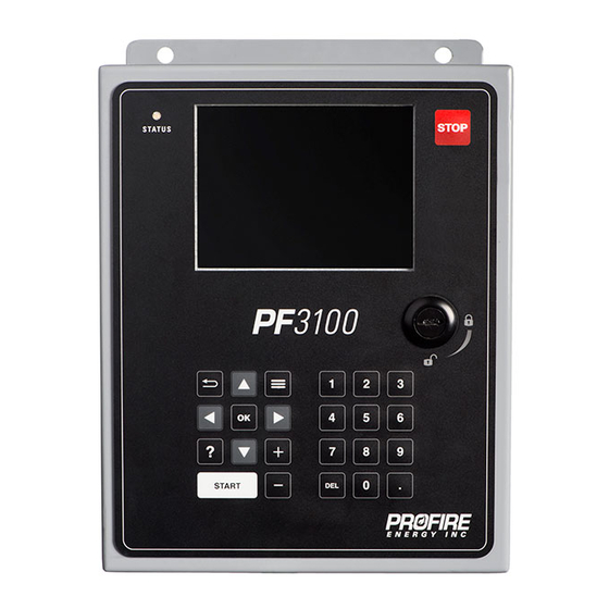
PF3100-00 USER INTERFACE CARD The PF3100 User Interface card is the primary access point for commissioning and monitoring the PF3100 system. It consists of a 5.7” color display and a full keypad for navigation and configuration, as well as an appliance status LED indicator and a USB port for data logging and settings file management. -
Page 10: Keypad
The keypad is intended to aid in commissioning and system navigation and must not be incorporated into any safety function. If user shutdown is a required safety function, then the BMS Controller card ESD input(s) or external ignition switch(es) must be used. Copyright © 2022, Profire Energy. All rights reserved. 855.PRO.FIRE | PROFIREENERGY.COM... -
Page 11: User Interface Display
Appliance Screen - press to highlight desired appliance as well as the Status Tab appliance, then press current state of every BMS controller in the appliance. Copyright © 2022, Profire Energy. All rights reserved. 855.PRO.FIRE | PROFIREENERGY.COM... - Page 12 (alarms, waits, warnings and main permissives) for the Appliance Screen - From Appliance Status Tab, appliance. Pressing on an Alerts Tab press alert displays additional troubleshooting details if available. Copyright © 2022, Profire Energy. All rights reserved. 855.PRO.FIRE | PROFIREENERGY.COM...
- Page 13 Trim Settings views. additional tuning settings. Dialog * This option is only visible when the Trim Channel (FARC/O Trim Wizard > O Trim Tab) is not set to Disabled Copyright © 2022, Profire Energy. All rights reserved. 855.PRO.FIRE | PROFIREENERGY.COM...
- Page 14 UI Boot Menu * It may take up to 30 Profire for instructions on seconds for the Boot Menu how and when to use the to appear. Boot Menu utilities. Copyright © 2022, Profire Energy. All rights reserved. 855.PRO.FIRE | PROFIREENERGY.COM...
-
Page 15: Status Led
All appliances are stopped Solid All appliances are running Green Solid Some appliances are running and one or more are stopped Green Blinking Status LED is malfunctioning Amber Contact Profire Copyright © 2022, Profire Energy. All rights reserved. 855.PRO.FIRE | PROFIREENERGY.COM... -
Page 16: Pfrn Controller Network Port
On – Flickering Port has intermittent power Check PFRN wire terminations Port is not communicating Check PFRN wire terminations Link Green On – Solid Port is communicating normally On – Flickering Copyright © 2022, Profire Energy. All rights reserved. 855.PRO.FIRE | PROFIREENERGY.COM... -
Page 17: Usb Port
Do not remove or install the battery unless the area is known to be 1 2 3 4 5 6 non-hazardous. 4.8.1 DETAILS Ex t Batt CR2032 Boot Voltage Reset LINK PF3100-00 XX:00:00:00:XX:XX 139750 Data Logging 2021-12-31 Type CR 2032 v1.3.x Copyright © 2022, Profire Energy. All rights reserved. 855.PRO.FIRE | PROFIREENERGY.COM... -
Page 18: Pf3101-00 Bms Controller Card
To Remove Key 13 12 11 10 STATUS SPST 80mA 4-20mA / Dry 4-20mA 12/24V 120 VAC/ Power Input 120 VDC Contact Inputs Dry Contact Inputs Powered Outputs Relay Output Copyright © 2022, Profire Energy. All rights reserved. 855.PRO.FIRE | PROFIREENERGY.COM... -
Page 19: Terminal Ratings
Ignition Switch Yes Ignite 3.3 V Keypad 3.3 V License Key 3.3 V The combined current requirements of the Start, POC, Aux In and ESD input devices cannot exceed 100mA. Copyright © 2022, Profire Energy. All rights reserved. 855.PRO.FIRE | PROFIREENERGY.COM... -
Page 20: Controller Power Input
High Voltage Wait Above 33.6V * Any running state Lockout High Voltage Alarm Disabled Any stopped state Alarm High Voltage Alarm * All listed voltage thresholds are +/- 1.0 V Copyright © 2022, Profire Energy. All rights reserved. 855.PRO.FIRE | PROFIREENERGY.COM... -
Page 21: Status Contact
> 50% Process temp < Low temp Low Temp Warning Process temp > Low temp Level > High Trip High Level/Flow Level < High Trip O – Open, C- Closed Copyright © 2022, Profire Energy. All rights reserved. 855.PRO.FIRE | PROFIREENERGY.COM... -
Page 22: High Fire Valve Solenoid Output
HFV OUTPUT BEHAVIOR BY CONTROLLER STATE HFV Output Mode Setting Condition Valve Not Purging Forced Draft Fan Purging Not Purging Purge Fan Purging E = Energized, D = De-energized Copyright © 2022, Profire Energy. All rights reserved. 855.PRO.FIRE | PROFIREENERGY.COM... -
Page 23: Main Valve Solenoid Output 2
Solenoid Output – 12V/24V waste gas shutoff valve Incinerator Control Incinerator Enable: Enabled 5.5.3 SSV2 OUTPUT BEHAVIOR BY CONTROLLER STATE Incinerator Enable Setting Disabled Enabled E = Energized, D = De-energized Copyright © 2022, Profire Energy. All rights reserved. 855.PRO.FIRE | PROFIREENERGY.COM... -
Page 24: Main Valve Solenoid Output 1
Solenoid Output – 12V/24V assist gas shutoff valve Incinerator Control Incinerator Enable: Enabled 5.6.3 SSV1 OUTPUT BEHAVIOR BY CONTROLLER STATE Incinerator Enable Setting Disabled Enabled E = Energized, D = De-energized Copyright © 2022, Profire Energy. All rights reserved. 855.PRO.FIRE | PROFIREENERGY.COM... -
Page 25: Pilot Valve Solenoid Output
Main Flame Detect setting must be enabled Energized under reignition conditions in accordance with configured Pilot Relight Mode and Pilot Relight Timeout settings (Controller Settings > Outputs > Ignition). Copyright © 2022, Profire Energy. All rights reserved. 855.PRO.FIRE | PROFIREENERGY.COM... -
Page 26: Auxiliary 4-20Ma Output
(Process temp, Pressure or 4-20mA Echo to PLC 4-20 Aux Out Mode: Desired Echo setting Level/Flow Controller Settings > Outputs > 4-20 Aux Out Not Used 4-20 Aux Out Mode: Disabled Copyright © 2022, Profire Energy. All rights reserved. 855.PRO.FIRE | PROFIREENERGY.COM... - Page 27 BMS input value is echoes An input of 12mA is represented as an identical 12mA Aux out on the Aux output as output signal. an identical 4-20mA signal Level/Flow Echo Copyright © 2022, Profire Energy. All rights reserved. 855.PRO.FIRE | PROFIREENERGY.COM...
-
Page 28: Remote Start Input
30 seconds* Ready Startup * The system does not register an energized to de-energized to energized transition unless the input remains in each state for at least 500ms. Copyright © 2022, Profire Energy. All rights reserved. 855.PRO.FIRE | PROFIREENERGY.COM... -
Page 29: Proof Of Closure Input
POC Contact Failed to Open warning Incinerator Enable: Enabled Incinerate De-energized No effect Incinerator PoC Valve: Assist Energized No effect Incinerate No Assist De-energized Lockout POC Contact Open alarm Copyright © 2022, Profire Energy. All rights reserved. 855.PRO.FIRE | PROFIREENERGY.COM... -
Page 30: Auxiliary Input
Controller Settings > Inputs > Aux In Contact Digital Input – Dry Contact Main permissive switch Aux In Contact Mode: Main Permissive Digital Input – Wet Contact Main Permissive Masking: As desired Copyright © 2022, Profire Energy. All rights reserved. 855.PRO.FIRE | PROFIREENERGY.COM... - Page 31 No effect POP Contact Failed to Open warning Off after main on Pilot De-energized No effect Energized No effect Any main fuel state De-energized Lockout POP Contact Open Alarm Copyright © 2022, Profire Energy. All rights reserved. 855.PRO.FIRE | PROFIREENERGY.COM...
- Page 32 Aux In Contact Open main permissive When Pilot Off mode is set to Off After Main On, the controller transitions to the Waiting state, then purges the system before reigniting and proceeding to Pilot. Copyright © 2022, Profire Energy. All rights reserved. 855.PRO.FIRE | PROFIREENERGY.COM...
-
Page 33: Emergency Shutdown Input
5.12.3 SYSTEM BEHAVIOR – EMERGENCY SHUTDOWN INPUT Scenario State Transition Controller Alerts ESD Input State Controller State Any running Lockout ESD Contact Open alarm De-energized Any stopped Alarm ESD Contact Open alarm Energized No effect Copyright © 2022, Profire Energy. All rights reserved. 855.PRO.FIRE | PROFIREENERGY.COM... -
Page 34: Fuel Pressure Input
UI Config Tab > Settings > UI Settings Pressure Units: As desired Controller Settings > Inputs > Fuel Pressure Input Not used Fuel Pressure Input Mode: Disabled All other settings: Ignored Copyright © 2022, Profire Energy. All rights reserved. 855.PRO.FIRE | PROFIREENERGY.COM... - Page 35 Controller State Pressure Input Energized No effect De-energized No effect High Fuel Pressure warning Any non-main state Any main fuel state De-energized Lockout High Fuel Pressure After Main On Copyright © 2022, Profire Energy. All rights reserved. 855.PRO.FIRE | PROFIREENERGY.COM...
-
Page 36: Level/Flow Input
Local Level/Flow Input: Disabled of this controller. appliance All other settings: As desired Controller Settings > Inputs > Level/Flow Input Not used Level/Flow Input Mode: Disabled Copyright © 2022, Profire Energy. All rights reserved. 855.PRO.FIRE | PROFIREENERGY.COM... - Page 37 Level/Flow input state is determined by a single input only). The input state of the Level/Flow input is determined by the first Local Level/Flow input to establish communication with the appliance only. Copyright © 2022, Profire Energy. All rights reserved. 855.PRO.FIRE | PROFIREENERGY.COM...
-
Page 38: Pfrn Controller Network
On – Flickering Port is communicating normally The Pwr and Link LED labels are incorrectly swapped on v1.3.x BMS Controller cards; the LED labelled “Pwr” is actually the “Link” LED and vice versa. Copyright © 2022, Profire Energy. All rights reserved. 855.PRO.FIRE | PROFIREENERGY.COM... -
Page 39: Pfrn I/O Network
On – Flickering The Pwr and Link LED labels are incorrectly swapped on v1.3.x BMS Controller cards; the LED labelled “Pwr” is actually the “Link” LED and vice versa. Copyright © 2022, Profire Energy. All rights reserved. 855.PRO.FIRE | PROFIREENERGY.COM... - Page 40 (e.g., A running system with three thermocouple devices measuring a single temperature input continues to run if one or two of the thermocouple inputs lose communication with the BMS controller). Copyright © 2022, Profire Energy. All rights reserved. 855.PRO.FIRE | PROFIREENERGY.COM...
-
Page 41: External Ignition Switch Input
Ready Ignite for more Lockout/Alarm External Switch Stuck alarm than 10s Any alert conditions that persist Run to Stop to Lockout Ready/Alarm after the lockout is acknowledged are displayed. Copyright © 2022, Profire Energy. All rights reserved. 855.PRO.FIRE | PROFIREENERGY.COM... -
Page 42: Bms Front Panel Led Output
SSV valve outputs energized Main Blue SSV valve outputs de-energized Pilot valve output energized Pilot Blue Pilot valve output de-energized Ignition coil output(s) energized Igniting Blue Ignition coil output(s) de-energized Copyright © 2022, Profire Energy. All rights reserved. 855.PRO.FIRE | PROFIREENERGY.COM... -
Page 43: Pf3102-00 Ion Pilot Card
Pilot Flame Detection 20kΩ source impedance 7 ION + Earth Ground 8 EGND 9 COIL - pulsed output Coil Output 2A Peak, ~100mA while sparking 10 COIL + Copyright © 2022, Profire Energy. All rights reserved. 855.PRO.FIRE | PROFIREENERGY.COM... -
Page 44: Ion Auxiliary Input
When returning from a high trip event, the controller does not consider the trip event to be cleared until the signal drops below the configured Ion Aux In Trip Point minus the configured Ion Aux In Deadband. Copyright © 2022, Profire Energy. All rights reserved. 855.PRO.FIRE | PROFIREENERGY.COM... -
Page 45: Ion Pilot Valve Output
Main Flame Detect setting must be enabled Energized under reignition conditions in accordance with configured Pilot Relight Mode and Pilot Relight Timeout settings (Controller Settings > Outputs > Ignition). Copyright © 2022, Profire Energy. All rights reserved. 855.PRO.FIRE | PROFIREENERGY.COM... -
Page 46: Main Ionization Flame Detection Input
Below 700mV voltage Alarm DC Low For reference only No effect Flame Diagnostic readings are displayed on the Flame Diagnostics screen. This value may exceed 3000mV under flame sharing conditions. Copyright © 2022, Profire Energy. All rights reserved. 855.PRO.FIRE | PROFIREENERGY.COM... - Page 47 Pilot flame detection is determined based on the flame strength of all configured pilots in accordance with the configured Minimum Pilots Running setting (Pilot Wizard > Ignition Settings Tab). This value may exceed 3000mV under flame sharing conditions. Copyright © 2022, Profire Energy. All rights reserved. 855.PRO.FIRE | PROFIREENERGY.COM...
-
Page 48: Pilot Ignition Coil Output
Coil output is energized with a pulsed output when Ignition Mode is set to Coil. Coil output is energized with a steady 12V output when Ignition Mode is set to HEI. Copyright © 2022, Profire Energy. All rights reserved. 855.PRO.FIRE | PROFIREENERGY.COM... -
Page 49: Pfrn Port
BMS and Pilot card. On – Solid Port is communicating normally 6.7.4 SYSTEM BEHAVIOR UPON COMMUNICATION LOSS Refer to BMS PFRN I/O Network System Behavior for behavior under communication loss conditions. Copyright © 2022, Profire Energy. All rights reserved. 855.PRO.FIRE | PROFIREENERGY.COM... -
Page 50: Pf3102-01 Uv Pilot Card
30 VDC max, 0.7mA minimum wetting current Not used Not used Flame Strength 18 4-20mA 30 V , 25mA maximum Not used 19 Not used PFRN I/O Network 20 PFRN 36 V 1A maximum Copyright © 2022, Profire Energy. All rights reserved. 855.PRO.FIRE | PROFIREENERGY.COM... -
Page 51: Ignition Enable Relay Contact
System Configuration E = Energized, D = De-energized Energized under reignition conditions in accordance with configured Pilot Relight Mode and Pilot Relight Timeout settings (Controller Settings > Outputs > Ignition). Copyright © 2022, Profire Energy. All rights reserved. 855.PRO.FIRE | PROFIREENERGY.COM... -
Page 52: Required Uv Flame Scanner Inputs
Lockout/Alarm UV Flame Detect Mismatch alarm De-energized De-energized Fault Lockout/Alarm UV Flame Detect Mismatch alarm Energized De-energized Flame detected Refer to Operating Sequence section for behavior De-energized Energized Flame not detected Copyright © 2022, Profire Energy. All rights reserved. 855.PRO.FIRE | PROFIREENERGY.COM... -
Page 53: Uv Flame Scanner Flame Strength Input
State System Configuration Controller Alerts Strength Input State Transition No effect * UV Flame strength reading does not affect system behavior and is displayed on the Flame Diagnostics screen. Copyright © 2022, Profire Energy. All rights reserved. 855.PRO.FIRE | PROFIREENERGY.COM... -
Page 54: Pfrn Port
Link Green Port is communicating On – Solid normally 7.5.4 SYSTEM BEHAVIOR UPON COMMUNICATION LOSS Refer to BMS PFRN I/O Network System Behavior for behavior under communication loss conditions. Copyright © 2022, Profire Energy. All rights reserved. 855.PRO.FIRE | PROFIREENERGY.COM... -
Page 55: Dip Switches
PF3102-01 XX:00:00:00:XX:XX Mode Reset 139750 UV Pilot Card 2021-12-31 v1.0 v1.0.x 20 - PFRN 7.7.2 INTENDED APPLICATIONS Application Configuration Requirements Connection Diagrams Not applicable for PF3102-01 UV Pilot Cards Copyright © 2022, Profire Energy. All rights reserved. 855.PRO.FIRE | PROFIREENERGY.COM... -
Page 56: Pf3102-03 Pilot Spark Card
Card Enable 3 EN 12/24V , 5mA maximum Ground 4 GND 5 COIL - Coil Output , 2A maximum 6 COIL + Coil Return 7 ION Ground return path Copyright © 2022, Profire Energy. All rights reserved. 855.PRO.FIRE | PROFIREENERGY.COM... -
Page 57: Power Input
Grp ABCD T4 Type Powered ignition output PF3102-03 Pilot Spark Card V1.1 8.4.2 INTENDED FIELD DEVICE CONNECTIONS Field Device Configuration Requirements Connection Diagrams Ignition coil UV Pilot to Spark Card Wiring Copyright © 2022, Profire Energy. All rights reserved. 855.PRO.FIRE | PROFIREENERGY.COM... -
Page 58: Pf3103-00 Temperature Card
9 PFRN 36 V 1A maximum *Input is safety rated only when configured for use with a dual element thermocouple. Inputs configured for single element thermocouples are not safety rated. Copyright © 2022, Profire Energy. All rights reserved. 855.PRO.FIRE | PROFIREENERGY.COM... -
Page 59: Thermocouple Inputs
Aux Process details Below Low Temp Setpoint Process Control No effect Low Process Temp warning High Auxiliary Temperature Warning displayed If temperature is above its configured High Temp Warning Setpoint. Copyright © 2022, Profire Energy. All rights reserved. 855.PRO.FIRE | PROFIREENERGY.COM... - Page 60 The input reading for redundant inputs is determined by the first communicating input that has a valid temperature reading (i.e., not open or out of range) only. High Auxiliary Temperature Warning displayed If temperature is above its configured High Temp Warning Setpoint. Copyright © 2022, Profire Energy. All rights reserved. 855.PRO.FIRE | PROFIREENERGY.COM...
-
Page 61: Pfrn Port
Link Green On – Solid Port is communicating normally 9.3.4 SYSTEM BEHAVIOR UPON COMMUNICATION LOSS Refer to BMS PFRN I/O Network System Behavior for behavior under communication loss conditions. Copyright © 2022, Profire Energy. All rights reserved. 855.PRO.FIRE | PROFIREENERGY.COM... -
Page 62: Pf3106-00 Network Card
12-24 V Power In 2 Vin - 6.3A maximum *Fused at 6.3A 3 EGND Port 1 Port 2 36 V PFRN Network Port 3 1A maximum Port 4 Port 5 Copyright © 2022, Profire Energy. All rights reserved. 855.PRO.FIRE | PROFIREENERGY.COM... -
Page 63: Power Input
Name PF3106-00 XX00-0000-XXXX 139750 Type Power input 2021-12-31 v2.1.x 10.2.2 INTENDED FIELD DEVICE CONNECTIONS Field Device Configuration Requirements Connection Diagrams 12V Power Supply Power Input Wiring 24V Power Supply Copyright © 2022, Profire Energy. All rights reserved. 855.PRO.FIRE | PROFIREENERGY.COM... -
Page 64: Pfrn Ports
Port is not to system and check PFRN wire communicating terminations at Network card and connected card. Link Green On – Solid Port is communicating normally On – Flickering Copyright © 2022, Profire Energy. All rights reserved. 855.PRO.FIRE | PROFIREENERGY.COM... -
Page 65: Pf3107-00 Modbus Card
RS-485, -6V – 6V Common Mode Range with reference to terminal Modbus RS-485 10 (RS-485 GND) RS-485 Port 1 Port 2 36 V PFRN Controller Network 1A maximum Port 3 Port 4 Copyright © 2022, Profire Energy. All rights reserved. 855.PRO.FIRE | PROFIREENERGY.COM... -
Page 66: Power Input
Name PF3107-00 XX:00:00:00:XX:XX Type Power input 139750 2021-12-31 v1.3.x 11.2.2 INTENDED FIELD DEVICE CONNECTIONS Field Device Configuration Requirements Connection Diagrams 12V Power Supply Power Input Wiring 24V Power Supply Copyright © 2022, Profire Energy. All rights reserved. 855.PRO.FIRE | PROFIREENERGY.COM... -
Page 67: Start Input
Output not currently supported on PF3107-00 Modbus card. Instead, use: PF3101-00 BMS Controller card Run Status contact, or N/A – Not currently supported PF3113-00 I/O Expansion card Normally Open Normally Closed Contacts Copyright © 2022, Profire Energy. All rights reserved. 855.PRO.FIRE | PROFIREENERGY.COM... -
Page 68: Modbus Connection
Input Parity: None Modbus Wiring module Baud rate: 9600 or 19200 * Power cycle of PF3100 is required following a change of the Baud rate. Slave Address: Last byte of BMS controller MAC address from Serial Number Label. e.g., A BMS controller with a MAC address of A0:00:00:00:00:2B has a Modbus address of 2B or 43 in decimal form. -
Page 69: Pfrn Ports
Port is not to system and check PFRN wire communicating terminations at Modbus card and connected card. Link Green On – Solid Port is communicating normally On – Flickering Copyright © 2022, Profire Energy. All rights reserved. 855.PRO.FIRE | PROFIREENERGY.COM... -
Page 70: Pf3113-00 I/O Expansion Card
18 Signal In 4-20 Mode: 30 V max, 25mA max 19 Signal Out Pass through output 30 V max, 25mA max PFRN I/O 20 PFRN 36 V 1A maximum Network Copyright © 2022, Profire Energy. All rights reserved. 855.PRO.FIRE | PROFIREENERGY.COM... -
Page 71: Normally Closed Dry Contact
Connected controller is not Purging CLOSED Purge Status Connected controller is Purging OPEN * Input must go below its configured setpoint minus deadband to transition from Closed to Open Copyright © 2022, Profire Energy. All rights reserved. 855.PRO.FIRE | PROFIREENERGY.COM... -
Page 72: Normally Open Dry Contact
Connected controller is not Purging OPEN Purge Status Connected controller is Purging CLOSED * Input must go below its configured setpoint minus deadband to transition from Closed to Open Copyright © 2022, Profire Energy. All rights reserved. 855.PRO.FIRE | PROFIREENERGY.COM... -
Page 73: Ma Output
I/O Wizard > Configure PID Parameters Dialog thermocouple input(s) Setpoint: As desired PID Parameters: As desired Direction: As desired Mode: Auto System Stop Output: As desired/required Output Limits: As desired/required Copyright © 2022, Profire Energy. All rights reserved. 855.PRO.FIRE | PROFIREENERGY.COM... - Page 74 O Trim profile. Output Calibration Wizard Ensure all outputs are calibrated prior to starting an appliance for use in a FARC application. Refer to Output Calibration Wizard section. Copyright © 2022, Profire Energy. All rights reserved. 855.PRO.FIRE | PROFIREENERGY.COM...
- Page 75 In the example above, the firing rate remains at 50%, the fuel channel output remains at 32% and the air channel output is increased to (the FARC Table value corresponding to a fuel output of 35%). Copyright © 2022, Profire Energy. All rights reserved. 855.PRO.FIRE | PROFIREENERGY.COM...
-
Page 76: Configurable I/O Expansion Inputs
Input 1-4: As per field wiring Analog Input from PLC from PLC All other settings: As desired Refer to BMS Controller Card Aux Output section for additional configuration details and output behavior. Copyright © 2022, Profire Energy. All rights reserved. 855.PRO.FIRE | PROFIREENERGY.COM... - Page 77 (via I/O Expansion card). Multi-BMS applications require each BMS to have a dedicated I/O Expansion card connected with the single Bleed Valve Proof of Open logical input assigned. Copyright © 2022, Profire Energy. All rights reserved. 855.PRO.FIRE | PROFIREENERGY.COM...
- Page 78 Input 1: Assign Input 1 from above Input 2: Assign Input 2 from above All other settings: As desired PF3113 Hardware Configuration DIP Switch 1: Floating DIP Switch 2: Ground Copyright © 2022, Profire Energy. All rights reserved. 855.PRO.FIRE | PROFIREENERGY.COM...
- Page 79 The input state of the redundant input is determined by the first input to establish communication with the BMS controller only. Copyright © 2022, Profire Energy. All rights reserved. 855.PRO.FIRE | PROFIREENERGY.COM...
- Page 80 The input state of the redundant input is determined by the first input to establish communication with the BMS controller only. Copyright © 2022, Profire Energy. All rights reserved. 855.PRO.FIRE | PROFIREENERGY.COM...
- Page 81 Outside position error FARC Fuel Channel Position of expected position Any stopped Alarm Any running Lockout Above Cross Limit Error FARC Cross Limit Error alarm setting Any stopped Alarm Copyright © 2022, Profire Energy. All rights reserved. 855.PRO.FIRE | PROFIREENERGY.COM...
- Page 82 Trim Tab). Trimming consists of applying an offset to the output value of the configured Trim Channel to achieve the configured Target O value for the current firing rate of the system. Copyright © 2022, Profire Energy. All rights reserved. 855.PRO.FIRE | PROFIREENERGY.COM...
-
Page 83: Pfrn Port
Link Green On – Solid Port is communicating normally 12.6.4 SYSTEM BEHAVIOR UPON COMMUNICATION LOSS Refer to BMS PFRN I/O Network System Behavior for behavior under communication loss conditions. Copyright © 2022, Profire Energy. All rights reserved. 855.PRO.FIRE | PROFIREENERGY.COM... -
Page 84: Operating Sequence
DOC-001149 v8.0 13 OPERATING SEQUENCE The PF3100 utilizes a state-based control scheme to monitor the system and control all safety outputs. Each state has specific entry and exit requirements and defined output behavior. The sections below outline the state transitions and safety output behavior for each controller state. Each BMS controller in an appliance operates... -
Page 85: Power On State
No alarm conditions or unacknowledged lockout messages present Low Voltage Restart setting is set to Enabled, AND Controller was running at last power Waiting down No alarm conditions or unacknowledged lockout messages present Copyright © 2022, Profire Energy. All rights reserved. 855.PRO.FIRE | PROFIREENERGY.COM... -
Page 86: Alarm State
Alarm condition present * via Ready Lockout message acknowledged by Lockout Alarm condition present user * via Ready 13.2.3 TRANSITIONS FROM THE ALARM STATE Scenario Condition Ready No alarm conditions present Copyright © 2022, Profire Energy. All rights reserved. 855.PRO.FIRE | PROFIREENERGY.COM... -
Page 87: Ready State
No alarm conditions or unacknowledged lockout messages present Lockout message acknowledged by Lockout user Alarm No alarm conditions present 13.3.3 TRANSITIONS FROM THE READY STATE Scenario Condition Alarm Alarm condition present Waiting Controller started by user Copyright © 2022, Profire Energy. All rights reserved. 855.PRO.FIRE | PROFIREENERGY.COM... -
Page 88: Lockout State
Process Control Flame loss Relight Attempts setting exceeded 13.4.3 TRANSITIONS FROM THE LOCKOUT STATE Scenario Condition Ready Lockout message acknowledged Alarm Lockout message acknowledged Alarm condition present via Ready Copyright © 2022, Profire Energy. All rights reserved. 855.PRO.FIRE | PROFIREENERGY.COM... -
Page 89: Waiting State
Card Output Output State Pilot De-energized PF3101-00 BMS Controller card SSV1 De-energized SSV2 De-energized Valve De-energized PF3102-00 Ion Pilot card Coil De-energized PF3102-01 UV Pilot card Ignition Enable Open Copyright © 2022, Profire Energy. All rights reserved. 855.PRO.FIRE | PROFIREENERGY.COM... - Page 90 Low Heat Standby Delay has elapsed below its Low Fire setpoint Process temperature is above its Pilot Off Mode setting is set to Off after Main On or Follow Main configured Low Fire setpoint Copyright © 2022, Profire Energy. All rights reserved. 855.PRO.FIRE | PROFIREENERGY.COM...
- Page 91 Controller stopped by user FARC Enable setting is Enabled, AND Startup Checks No alarm or wait conditions present FARC Enable setting is Disabled, AND Ignition No alarm or wait conditions present Copyright © 2022, Profire Energy. All rights reserved. 855.PRO.FIRE | PROFIREENERGY.COM...
-
Page 92: Startup Checks State
13.6.3 TRANSITIONS FROM THE STARTUP CHECKS STATE Scenario Condition Alarm condition present Lockout Controller stopped by user Airflow detected Waiting Wait condition present Proven Absence of airflow proven No alarm or wait conditions present Pre-Purge Copyright © 2022, Profire Energy. All rights reserved. 855.PRO.FIRE | PROFIREENERGY.COM... -
Page 93: Proven Pre-Purge Sequence
Scenario Condition Alarm condition present Lockout Controller stopped by user Purge position not proven Waiting Wait condition present Prove Airflow Purge position proven No alarm or wait conditions present Copyright © 2022, Profire Energy. All rights reserved. 855.PRO.FIRE | PROFIREENERGY.COM... - Page 94 Alarm condition present Controller stopped by user Lockout Purge position not proven Airflow not proven Waiting Wait condition present Pre-Purge Airflow has been proven No alarm or wait conditions present Copyright © 2022, Profire Energy. All rights reserved. 855.PRO.FIRE | PROFIREENERGY.COM...
- Page 95 Request Pilot Pre-purge has completed FARC enabled, AND Position successfully No alarm or wait conditions present Pre-purge has completed FARC disabled, AND Ignition successfully No alarm or wait conditions present Copyright © 2022, Profire Energy. All rights reserved. 855.PRO.FIRE | PROFIREENERGY.COM...
- Page 96 TRANSITIONS FROM THE REQUEST PILOT POSITION STATE Scenario Condition Alarm condition present Lockout Controller stopped by user Pilot position not proven Waiting Wait condition present Ignition Pilot position proven No alarm or wait conditions present Copyright © 2022, Profire Energy. All rights reserved. 855.PRO.FIRE | PROFIREENERGY.COM...
-
Page 97: Ignition State
Pilot ignition has failed less than 3 times consecutively Flame loss Relight Attempts settings has not been exceeded No alarm or wait conditions present, AND Pilot Successful pilot flame ignition Minimum Pilots Running setting is satisfied Copyright © 2022, Profire Energy. All rights reserved. 855.PRO.FIRE | PROFIREENERGY.COM... -
Page 98: Pilot State
PF3102-01 UV Pilot card Ignition Enable Open Energized under reignition conditions in accordance with configured Pilot Relight Mode and Pilot Relight Timeout settings (Controller Settings > Outputs > Ignition). Copyright © 2022, Profire Energy. All rights reserved. 855.PRO.FIRE | PROFIREENERGY.COM... - Page 99 – PID Control below its Low Fire setpoint Process temperature is above its Pilot Off Mode setting is set to Disabled or Off at Setpoint configured Low Fire setpoint Copyright © 2022, Profire Energy. All rights reserved. 855.PRO.FIRE | PROFIREENERGY.COM...
- Page 100 Incinerator Enable setting is set to Enabled Process Control Process temperature is below its No main permissive conditions present, AND - High Fire configured Process setpoint Low Fire Mode setting is set to Disabled Copyright © 2022, Profire Energy. All rights reserved. 855.PRO.FIRE | PROFIREENERGY.COM...
-
Page 101: Low Fire State
Waste Gas On setpoint Process Control Process temperature is above its – High Fire configured Process setpoint Process temperature is below its Process Control – Incinerate configured Waste Gas On setpoint Copyright © 2022, Profire Energy. All rights reserved. 855.PRO.FIRE | PROFIREENERGY.COM... - Page 102 Process temperature is below its 4-20 Aux Out Mode setting is set to PID Control, AND – PID Control configured Process setpoint No alarm or wait or main permissive conditions present Copyright © 2022, Profire Energy. All rights reserved. 855.PRO.FIRE | PROFIREENERGY.COM...
-
Page 103: Process Control States
Low Fire Mode setting is set to Disabled, AND Process setpoint Pilot Off Mode is set to Disabled or Off at Setpoint Process temp above configured Low Fire Process setpoint Copyright © 2022, Profire Energy. All rights reserved. 855.PRO.FIRE | PROFIREENERGY.COM... - Page 104 No alarm or wait or main permissive conditions present Incinerate Process temperature is above its configured No alarm or wait or main permissive conditions present No Assist Assist Gas Off Setpoint Copyright © 2022, Profire Energy. All rights reserved. 855.PRO.FIRE | PROFIREENERGY.COM...
- Page 105 Pilot Off Mode setting is set to Disabled or Off at Setpoint Waste Gas Off setpoint Process temperature is below its configured Incinerate No alarm or wait or main permissive conditions present Assist Gas Off Setpoint Copyright © 2022, Profire Energy. All rights reserved. 855.PRO.FIRE | PROFIREENERGY.COM...
- Page 106 Process setpoint and below its Low Fire setpoint Low Heat Standby Delay has elapsed Process temperature is above its configured Pilot Off Mode setting is set to Disabled or Off at Setpoint Low Fire setpoint Copyright © 2022, Profire Energy. All rights reserved. 855.PRO.FIRE | PROFIREENERGY.COM...
-
Page 107: Installation
Warning: Installation and modification shall not be performed while the system is energized. Disconnect power source prior to connecting devices or modifying wiring. Installers and commissioners of the PF3100 system must: Understand local codes and how they apply to the installation (for both electrical and mechanical aspects •... - Page 108 Any conduit entry ports in use must be sealed in accordance with local electrical code(s), • • Each unused conduit entry port must be sealed with appropriately sized and rated pipe plugs, Thermocouple probe must be installed in an appropriately rated thermowell. • Copyright © 2022, Profire Energy. All rights reserved. 855.PRO.FIRE | PROFIREENERGY.COM...
-
Page 109: Hardware Installation Diagrams
1. Install four #10-32 screws through the card into the enclosure standoffs. 2. Tighten to 26 in•lbs 3. Close enclosure door and secure lock with a flat head screwdriver. Copyright © 2022, Profire Energy. All rights reserved. 855.PRO.FIRE | PROFIREENERGY.COM... -
Page 110: Connection Diagrams
“+” terminal in the diagram and the Signal In terminal Pressure+ corresponds to the “-“ terminal in the diagram. Level- 2. The PF3100 system uses energized-to-run logic for all digital Digital Input Switch Level+ inputs. Wire to NO or NC contacts accordingly. - Page 111 “-“ terminal in the diagram. 2. PLC output signal must be referenced about BMS Controller card Common terminal (terminal 2). OUT - OUT + Pressure- PLC Analog Output Pressure+ Card Level- Level+ Copyright © 2022, Profire Energy. All rights reserved. 855.PRO.FIRE | PROFIREENERGY.COM...
- Page 112 Caution: Do not connect solenoid device minus (-) terminals to ground, as the BMS solenoid output minus (-) terminals are not grounded. Caution: Do not jumper solenoid minus terminals together under any circumstance, as this will compromise the safety integrity of the system. Copyright © 2022, Profire Energy. All rights reserved. 855.PRO.FIRE | PROFIREENERGY.COM...
- Page 113 BMS Controller card Status contact wiring shown as an 12-24 VDC Power Source example only. The I/O Expansion card status contacts Common can be wired in the same way. Earth GND Control Panel Status Indicator Copyright © 2022, Profire Energy. All rights reserved. 855.PRO.FIRE | PROFIREENERGY.COM...
- Page 114 6mm (0.25”). Warning: Failure to provide a low-impedance path from the burner assembly to the PF3100 may result in electric shock, product damage, failure to ignite the pilot, or failure to detect flame. Warning: Flame rods are not intended to be mounted in Class I, Division 1 or 2 hazardous locations.
- Page 115 6mm (0.25”). Warning: Failure to provide a low-impedance path from the burner assembly to the PF3100 may result in electric shock, product damage, failure to ignite the pilot, or failure to detect flame. Warning: Flame rods are not intended to be mounted in Class I, Division 1 or 2 hazardous locations.
- Page 116 6mm (0.25”). Warning: Failure to provide a low-impedance path from the burner assembly to the PF3100 may result in electric shock, product damage, failure to ignite the pilot, or failure to detect flame. Warning: Flame rods are not intended to be mounted in Class I, Division 1 or 2 hazardous locations.
- Page 117 1. A fault tolerant safety relay must be used for this application 9 10 11 Earth GND Ignition Enable Contact N.O. SPST 120 VAC/DC, 80mA max HEI Module supply power terminals PF3102-01 UV Pilot Card v1.0 Copyright © 2022, Profire Energy. All rights reserved. 855.PRO.FIRE | PROFIREENERGY.COM...
- Page 118 4. Thermocouple wires should not be run in the same TC1A conduit as high-noise signals (e.g., valve wires, motor wires, etc.) 9 – PFRN IO Bus TC1B PF3103-00 TC Temp. Module v1.x Dual Type K Thermocouple Copyright © 2022, Profire Energy. All rights reserved. 855.PRO.FIRE | PROFIREENERGY.COM...
- Page 119 2. Move Dip switch to the “Term” position to activate the termination resistor. Termination is recommended if the RS-485 Master Modbus card is on the end of the Modbus chain Copyright © 2022, Profire Energy. All rights reserved. 855.PRO.FIRE | PROFIREENERGY.COM...
- Page 120 Green Installation Notes: 1. Solid core Cat5e or higher rated Ethernet cable should be used for all PFRN connections. 2. PFRN cable runs must not exceed 250m (820 ft). Copyright © 2022, Profire Energy. All rights reserved. 855.PRO.FIRE | PROFIREENERGY.COM...
- Page 121 PWR Out Mode Mode PF3113-00 XX:00:00:00:XX:XX PF3113-00 XX:00:00:00:XX:XX 139750 139750 IO Expansion Card Reset IO Expansion Card Reset 2021-12-31 2021-12-31 V2.0 V2.0 v2.0.x 20 - PFRN v2.0.x 20 - PFRN Copyright © 2022, Profire Energy. All rights reserved. 855.PRO.FIRE | PROFIREENERGY.COM...
- Page 122 DOC-001149 v8.0 14.3.29 COMBINED LOW/HIGH PRESSURE SWITCH WIRING Installation Notes: 1. The PF3100 system uses energized-to-run logic for all digital inputs. Wire to NO contact of the low-pressure switch and NC contact of the high-pressure switch. PF3101-00 BMS Controller Card Digital High Pressure 2.
-
Page 123: System Configuration
An Appliance is made up of one or more BMS controller cards working together and represents the actual heating appliance that exists on site. Each appliance on site must be represented as a separate appliance on the PF3100. A single UI card can control multiple appliances, but information cannot be shared between them. -
Page 124: System Scaling
15.8 SYSTEM SCALING At a minimum, each PF3100 system is comprised of one BMS controller card, one ion pilot card and one temperature card for each appliance under control. Only one User Interface card is required to control all the appliances in a system. -
Page 125: Commissioning
Warning: System settings and appliance configuration details must only be modified by qualified personnel familiar with the both the appliance under PF3100 control and related plant processes that could be affected. 16.1 PASSWORDS Each setting and configuration wizard has a pre-defined security level based on its potential safety and reliability impact. -
Page 126: User Interface Settings
The L1 password or higher must be used to access non-safety Level 1 Enabled critical settings. Password Enabled Enabled Disabled The L1 settings can be modified with no password. Copyright © 2022, Profire Energy. All rights reserved. 855.PRO.FIRE | PROFIREENERGY.COM... -
Page 127: Appliance Wizard
Review Tab. 16.4.3 REVIEW TAB 11. Ensure that there are no errors and select “Accept” to save all changes and exit the Appliance Wizard. Copyright © 2022, Profire Energy. All rights reserved. 855.PRO.FIRE | PROFIREENERGY.COM... -
Page 128: Temperature Wizard
Single The temperature input is a single-element thermocouple. Input Type Dual Dual The temperature input is a dual-element thermocouple. Copyright © 2022, Profire Energy. All rights reserved. 855.PRO.FIRE | PROFIREENERGY.COM... - Page 129 Deadband 3.6 °F 3.6 °F – 180 °F sporadically when the temperature is near the setpoint. 16. Select “Finished” then press then to advance to the Temp Modules Tab. Copyright © 2022, Profire Energy. All rights reserved. 855.PRO.FIRE | PROFIREENERGY.COM...
- Page 130 Review Tab. 16.5.3 REVIEW TAB 19. Ensure that there are no errors and select “Accept” to save all changes and exit the Temperature Wizard. Copyright © 2022, Profire Energy. All rights reserved. 855.PRO.FIRE | PROFIREENERGY.COM...
-
Page 131: Pilot Wizard
Enabled/Disabled Enabled Disabled The ignition card is ignored by the system. 23. Press then to advance to the Ignition Settings Tab. Copyright © 2022, Profire Energy. All rights reserved. 855.PRO.FIRE | PROFIREENERGY.COM... - Page 132 Review Tab. 16.6.3 REVIEW TAB 26. Ensure that there are no errors and select “Accept” to save all changes and exit the Pilot Wizard. Copyright © 2022, Profire Energy. All rights reserved. 855.PRO.FIRE | PROFIREENERGY.COM...
-
Page 133: I/O Expansion Wizard
Specifies the deadband applied around each setpoint to prevent Deadband Any above 0 fluctuation between states when input is near the trip points. 29. Press then to advance to the I/O Modules Tab. Copyright © 2022, Profire Energy. All rights reserved. 855.PRO.FIRE | PROFIREENERGY.COM... - Page 134 * Only applicable when Dry Contact Any configured I/O Specifies the I/O Expansion input used to determine dry mode above is set to Temp Setpoint expansion input contact behavior. Trip or Input Setpoint Trip. Copyright © 2022, Profire Energy. All rights reserved. 855.PRO.FIRE | PROFIREENERGY.COM...
- Page 135 Review Tab. 16.7.4 REVIEW TAB 35. Ensure that there are no errors and select “Accept” to save all changes and exit the I/O Expansion Wizard. Copyright © 2022, Profire Energy. All rights reserved. 855.PRO.FIRE | PROFIREENERGY.COM...
-
Page 136: Output Calibration Wizard
Review Tab. 16.8.2 REVIEW TAB 44. Ensure that there are no errors and select “Accept” to save all changes and exit the Output Calibration Wizard. Copyright © 2022, Profire Energy. All rights reserved. 855.PRO.FIRE | PROFIREENERGY.COM... -
Page 137: Farc/Otrim Wizard
Specifies that the system uses FARC Curve A. Selected Curve Curve B Specifies that the system uses FARC Curve A. 47. Press then to advance to the Channels Tab. Copyright © 2022, Profire Energy. All rights reserved. 855.PRO.FIRE | PROFIREENERGY.COM... - Page 138 0 – 100 % Specifies the channel output position when in the Pilot state. Off Position 0 – 100 % Specifies the channel output position when stopped and not purging. Copyright © 2022, Profire Energy. All rights reserved. 855.PRO.FIRE | PROFIREENERGY.COM...
- Page 139 * All unconfigured columns on the table are linearly interpolated from the configured points. 51. Ensure that both Curve A and Curve B are configured correctly and select “Finished”. 52. Press then to advance to the O Trim Tab. Copyright © 2022, Profire Energy. All rights reserved. 855.PRO.FIRE | PROFIREENERGY.COM...
- Page 140 Specifies the integral term used by the O Trim PI Integral Time 0 – 100 min algorithm. Specifies the sample time used by the O Trim PI System Delay Time 1 – 300 sec algorithm. Copyright © 2022, Profire Energy. All rights reserved. 855.PRO.FIRE | PROFIREENERGY.COM...
- Page 141 Review Tab. 16.9.4 REVIEW TAB 58. Ensure that there are no errors and select “Accept” to save all changes and exit the FARC/O Trim Wizard. Copyright © 2022, Profire Energy. All rights reserved. 855.PRO.FIRE | PROFIREENERGY.COM...
-
Page 142: Bms Controller Settings
Temperature Wizard Adjust Setpoints Dialog above for configuration options and descriptions. 85 °C Low Fire SP 185 °F 80 °C Process Temp SP 176 °F 0 °C Low Temp SP 32 °F Copyright © 2022, Profire Energy. All rights reserved. 855.PRO.FIRE | PROFIREENERGY.COM... - Page 143 Specifies the time for which the system remains Low to High Fire Delay 30 s 30 s - 600 s in the Low Fire state before proceeding to High Fire. Copyright © 2022, Profire Energy. All rights reserved. 855.PRO.FIRE | PROFIREENERGY.COM...
- Page 144 Specifies the maximum rate of change Rate Limit Primary 100%/s 1 %/s – 100 %/s of the BMS Controller Aux output during primary PID control. Copyright © 2022, Profire Energy. All rights reserved. 855.PRO.FIRE | PROFIREENERGY.COM...
- Page 145 Specifies the maximum rate of change Rate Limit Secondary 100%/s 1 %/s – 100 %/s of the BMS Controller Aux output during secondary PID control. Copyright © 2022, Profire Energy. All rights reserved. 855.PRO.FIRE | PROFIREENERGY.COM...
- Page 146 Specifies the input used as a secondary PID input. Input Expansion Input Any configured I/O Staging Input Specifies the I/O Expansion input used as a staging input expansion input Copyright © 2022, Profire Energy. All rights reserved. 855.PRO.FIRE | PROFIREENERGY.COM...
- Page 147 Specifies the time for which the Low Heat Standby conditions must be met Low Heat Standby Delay 1 min 1 min – 1440 min for the system to initiate a Low Heat Standby state transition. Copyright © 2022, Profire Energy. All rights reserved. 855.PRO.FIRE | PROFIREENERGY.COM...
- Page 148 0 °F 0 °F - 2430 °F Specifies the maximum temperature increase allowed over a specified period upon start up. Time Step Size 0 min 0 min – 65535 min Copyright © 2022, Profire Energy. All rights reserved. 855.PRO.FIRE | PROFIREENERGY.COM...
- Page 149 1.8 °F - 360 °F when the process temperature is near the setpoints. 2 °C 2 °C - 2 °C Waste Gas On Deadband 3.6 °F 3.6 °F - 3.6 °F Copyright © 2022, Profire Energy. All rights reserved. 855.PRO.FIRE | PROFIREENERGY.COM...
- Page 150 - All I/O Expansion waits - Low Fuel Pressure - Low Fuel Pressure Dry Contact - Low Tank Level - Tank Level Contact Open Disabled Input waits are not ignored. Copyright © 2022, Profire Energy. All rights reserved. 855.PRO.FIRE | PROFIREENERGY.COM...
- Page 151 A low-pressure event is (1) a pressure input reading below its configured 4-20 Low Fuel Pressure SP when it is configured in 4- 20 Mode, and (2) a de-energized Auxiliary input when it is configured in Low Fuel Pressure Mode. Copyright © 2022, Profire Energy. All rights reserved. 855.PRO.FIRE | PROFIREENERGY.COM...
- Page 152 Description The POC input is connected to a proof Enabled of closure switch on the main valves. Proof of Closure Disabled Disabled The proof of closure input is ignored. Copyright © 2022, Profire Energy. All rights reserved. 855.PRO.FIRE | PROFIREENERGY.COM...
- Page 153 0.4 gal prevent fluctuation between states. Specifies the time for which a low- Low Level/Flow Delay 2 s – 20 s level/flow event must be present before the system acts. Copyright © 2022, Profire Energy. All rights reserved. 855.PRO.FIRE | PROFIREENERGY.COM...
- Page 154 Specifies the minimum allowable Aux output signal when in a main 40 % 0 % - 70 % Rate state. Applicable when 4-20 Aux Out Mode setting is set to BMS PID. Copyright © 2022, Profire Energy. All rights reserved. 855.PRO.FIRE | PROFIREENERGY.COM...
- Page 155 The HFV output is connected to a relay enabling a HFV Output Mode Valve forced draft fan. The HFV output is connected to a relay enabling a purge Purge Fan fan. Copyright © 2022, Profire Energy. All rights reserved. 855.PRO.FIRE | PROFIREENERGY.COM...
- Page 156 Min Controllers Running 1 controller 1 – 16 controllers to remain running. * Cannot be set higher than the Appliance Size for multi-burner applications. Copyright © 2022, Profire Energy. All rights reserved. 855.PRO.FIRE | PROFIREENERGY.COM...
- Page 157 2 min alarm. 1 – 120 min Applicable waits: I/O Expansion Input Invalid • I/O Expansion Input Low Trip • I/O Expansion Input High Trip • I/O Expansion Input Open Copyright © 2022, Profire Energy. All rights reserved. 855.PRO.FIRE | PROFIREENERGY.COM...
- Page 158 Ion Aux In Offset 0.0 % -20 % - 20 % Specifies the offset applied to the Ion Pilot card Aux input readings. Ion Aux In Scaling Factor 0.00 Read Only Copyright © 2022, Profire Energy. All rights reserved. 855.PRO.FIRE | PROFIREENERGY.COM...
- Page 159 22.0 mA 19 mA – 22 mA Specifies the trip points for the 4-20mA out of range alarms. 4-20 Low Range Limit 3.0 mA 3 mA – 5 mA Copyright © 2022, Profire Energy. All rights reserved. 855.PRO.FIRE | PROFIREENERGY.COM...
-
Page 160: Farc Tuning Settings
Fuel-Air Ratio Table - Fuel 0 – 100% firing rate. Specifies the auxiliary channel actuator Fuel-Air Ratio Table – Aux Channels 0 – 100% position for a given firing rate. Copyright © 2022, Profire Energy. All rights reserved. 855.PRO.FIRE | PROFIREENERGY.COM... -
Page 161: O 2 Trim Tuning
Specifies the desired O concentration for a given firing rate. Trim Table – Max Trim 0% - +100% Specifies the desired maximum offset applied for a given firing rate. Copyright © 2022, Profire Energy. All rights reserved. 855.PRO.FIRE | PROFIREENERGY.COM... -
Page 162: Test System
(in conjunction with the Swap Wizard) identically. 64. Use the Settings Backup tool to save settings to a USB storage device. Copyright © 2022, Profire Energy. All rights reserved. 855.PRO.FIRE | PROFIREENERGY.COM... -
Page 163: System Operation
DOC-001149 v8.0 17 SYSTEM OPERATION The following sections outline the procedures required for basic operation of a commissioned PF3100 system including starting and stopping controllers or appliances, finding status and alert information, making quick setpoint adjustments and acknowledging lockout messages. -
Page 164: Accessing System Status Information
Use the keypad to adjust the settings as desired. The displayed settings are dependent on the security level of the password used to access the menu. Copyright © 2022, Profire Energy. All rights reserved. 855.PRO.FIRE | PROFIREENERGY.COM... -
Page 165: Stopping The System
User Interface – Navigate to desired appliance status screen, press , select “This Appliance”, then press • Stop all appliances: User Interface – From any screen, press , select “All Appliances”, then press • Copyright © 2022, Profire Energy. All rights reserved. 855.PRO.FIRE | PROFIREENERGY.COM... -
Page 166: Reigniting A Lost Pilot
Remote Start input: Toggle input from energized to de-energized to energized within 30 seconds. Modbus – Write Acknowledge command to the Clear Shutdown Code Modbus register (30143/40143). Refer • PF3107-00 Modbus Register Map for details. Copyright © 2022, Profire Energy. All rights reserved. 855.PRO.FIRE | PROFIREENERGY.COM... -
Page 167: Advanced Pf3100 Software Features
DOC-001149 v8.0 17.8 ADVANCED PF3100 SOFTWARE FEATURES 17.8.1 PID CONTROL Below is a brief overview of the PID control features available on the PF3100. Refer to PID Tuning Guide document for additional details and configuration information. The following terms are used to describe the system behavior in the various PID control modes: •... - Page 168 The PF3100 allows specific actuator positions to be configured in 5% firing rate increments to control the fuel-air ratio of the combustion inputs across the entire operating range of the appliance.
-
Page 169: Software Utilities
DOC-001149 v8.0 18 SOFTWARE UTILITIES The following section outlines the diagnostic, troubleshooting and upgrade tools available on all PF3100 systems. 18.1 QUICK START SETUP TOOL The Quick Start Setup tool is accessible only when the system has no configured appliances. The tool guides the user through a firmware update and the Appliance, Temperature and Pilot Wizards to achieve basic system configuration. - Page 170 2. The Swap Modules Tab lists all the non-communicating cards that are expected to be communicating with the system. Select a card and assign an appropriate replacement card. 3. Repeat previous step for all listed cards. Copyright © 2022, Profire Energy. All rights reserved. 855.PRO.FIRE | PROFIREENERGY.COM...
- Page 171 UI card settings. 1. Navigate to the Swap Wizard and select “UI”. 2. Select a valid settings file, confirm the on-screen network map and select “Yes” to complete the swap. Copyright © 2022, Profire Energy. All rights reserved. 855.PRO.FIRE | PROFIREENERGY.COM...
-
Page 172: Diagnostics
This information is useful when troubleshooting communication issues. 18.3.3 SYSTEM DATA The System Data Screen displays raw input and output data for the inputs and outputs of every connected card. This screen is useful for troubleshooting. Copyright © 2022, Profire Energy. All rights reserved. 855.PRO.FIRE | PROFIREENERGY.COM... -
Page 173: Logging
1. Navigate to the Data Logging tool and press , select desired appliance, then select “Configure”. 2. Specify the logging interval for each listed input and output and select “Finished” Copyright © 2022, Profire Energy. All rights reserved. 855.PRO.FIRE | PROFIREENERGY.COM... - Page 174 The Export tool saves Event Log and/or Data Log data to a USB storage device. Navigate to the Export tool and press , then follow the on-screen instructions to save desired information to the connected USB drive. Copyright © 2022, Profire Energy. All rights reserved. 855.PRO.FIRE | PROFIREENERGY.COM...
-
Page 175: Settings
18.5.1.1 SETTINGS BACKUP PROCEDURE 4. Insert a USB storage device into the USB port on the PF3100-00 User Interface card. 5. Navigate to the Settings Backup tool and press , then select the settings to be saved. - Page 176 18.5.2.1 SETTINGS RESTORE PROCEDURE 1. Insert USB drive containing desired settings file into the USB port on the PF3100-00 User Interface card. 2. Navigate to the Settings Restore tool and press 3. Select desired settings file from the USB device or local UI storage.
-
Page 177: Firmware
For other connected cards, refer to the Network Discovery tool above. 18.6.2 FIRMWARE UPDATE The Firmware Update tool allows for all PF3100 cards to be field upgraded with an update file saved to a USB drive. 18.6.2.1 FIRMWARE UPDATE PROCEDURE 1. - Page 178 10. Select Restore to load the auto-saved settings from before the firmware update or navigate to the Settings Restore Utility to load saved settings from the USB storage device. Copyright © 2022, Profire Energy. All rights reserved. 855.PRO.FIRE | PROFIREENERGY.COM...
-
Page 179: Maintenance
19.4 DECOMMISSIONING The useful life of the PF3100 is 10 years. When decommissioning the system, the appliance should be safely shut down (i.e., all safety outputs are turned off and there are no gas leaks on site). Once the appliance is in a safe state, the power should be disconnected from the PF3100. -
Page 180: Alert Codes
A wiring or hardware error is detected on the Pilot- terminal (terminal 12) Pilot Solenoid Error 1016 of the BMS Controller card. * Alarm 1020 has the same name Copyright © 2022, Profire Energy. All rights reserved. 855.PRO.FIRE | PROFIREENERGY.COM... - Page 181 Profire. 1030 Factory Calibration Error * This alarm can only be present when the Factory Cal Error Mode setting (BMS Settings > Calibration > BMS) is set to Alarm. Copyright © 2022, Profire Energy. All rights reserved. 855.PRO.FIRE | PROFIREENERGY.COM...
- Page 182 Ignition Switch Stuck The BMS Controller Ignition Switch input is stuck in the Start position. 1033 Auxiliary Temperature High ESD Auxiliary temperature input reading is above its High Temp SP setting. Copyright © 2022, Profire Energy. All rights reserved. 855.PRO.FIRE | PROFIREENERGY.COM...
- Page 183 High Safety Core Temperature Too 1051 Card temperature is below rated minimum operating temperature 1052 Reserved 1053 Controller Settings CRC Failed The BMS Controller settings are invalid. 1054 Reserved Copyright © 2022, Profire Energy. All rights reserved. 855.PRO.FIRE | PROFIREENERGY.COM...
- Page 184 1071 No Valid Auxiliary Temperature * Pressing the OK button on the alert text opens a dialog that identifies the offending card and input. 1072 Reserved Copyright © 2022, Profire Energy. All rights reserved. 855.PRO.FIRE | PROFIREENERGY.COM...
- Page 185 UV Flame Detect Mismatch or (2) both de-energized. 1092 UV Input Out of Range UV Scanner input invalid. Contact Profire. 1093 UV Input Address Fault Internal UV Pilot card fault. Contact Profire. Copyright © 2022, Profire Energy. All rights reserved. 855.PRO.FIRE | PROFIREENERGY.COM...
- Page 186 The difference between the requested and actual position of the FARC air 1106 FARC Air Channel Position Error actuator exceeds the configured position error threshold. 1107 Reserved Copyright © 2022, Profire Energy. All rights reserved. 855.PRO.FIRE | PROFIREENERGY.COM...
- Page 187 * This alarm is ignored when the controller is not actively trimming O (e.g., the controller is not in Process Control or the warmup conditions have not been met. Copyright © 2022, Profire Energy. All rights reserved. 855.PRO.FIRE | PROFIREENERGY.COM...
- Page 188 4-20mA input or TC Flame Detect is enabled with a UV Pilot card. Trim Enabled Without Stack Sensor Warmup Mode setting is configured as Stack Temp with no valid 1148 Input temperature input assigned. Copyright © 2022, Profire Energy. All rights reserved. 855.PRO.FIRE | PROFIREENERGY.COM...
- Page 189 Error the FARC/O2 Trim Wizard. O2 Trim setting is Enabled and no O2 Sensor has been configured in the 1156 O2 Trim Requires an O2 Sensor I/O Expansion Wizard. Copyright © 2022, Profire Energy. All rights reserved. 855.PRO.FIRE | PROFIREENERGY.COM...
-
Page 190: Waits
2008 Loss of Communications * This wait can only be present when the Comm Loss Restart setting (BMS Settings > Setup > Other) is set to Enabled. Copyright © 2022, Profire Energy. All rights reserved. 855.PRO.FIRE | PROFIREENERGY.COM... - Page 191 Cascaded PID: PID Process Setpoint is at the configured Primary Setpoint Min setting and the Process Temperature is greater than the Primary Setpoint Min setting and Secondary Input is greater than the Secondary Process Setpoint minus Deadband. Copyright © 2022, Profire Energy. All rights reserved. 855.PRO.FIRE | PROFIREENERGY.COM...
-
Page 192: Warnings
A Temperature card input configured as a High Temp ESD input is reading 3011 High Auxiliary Temperature a value above its High Temp Warning SP setting. Copyright © 2022, Profire Energy. All rights reserved. 855.PRO.FIRE | PROFIREENERGY.COM... - Page 193 IO Expansion Configuration 3021 Error FARC Air/Fuel/Aux Sensor Secondary PID * Pressing the OK button on the alert text opens a dialog that identifies the offending card and input. Copyright © 2022, Profire Energy. All rights reserved. 855.PRO.FIRE | PROFIREENERGY.COM...
- Page 194 * This warning is hidden when the controller is not actively trimming O (e.g., the controller is not in Process Control or the warmup conditions have not been met. 3029 Manual O Trim Trim Manual Mode setting is enabled Copyright © 2022, Profire Energy. All rights reserved. 855.PRO.FIRE | PROFIREENERGY.COM...
-
Page 195: Main Permissives
High Setpoint setting. IO Expansion Analog Input 4005 High * Pressing the OK button on the alert text opens a dialog that identifies the offending card and input. Copyright © 2022, Profire Energy. All rights reserved. 855.PRO.FIRE | PROFIREENERGY.COM... - Page 196 Process Temperature is greater than the Process Setpoint. Cascaded PID: PID Process Setpoint is at the configured Primary Setpoint Min setting and the Process Temperature is greater than the Primary Setpoint Min setting. Copyright © 2022, Profire Energy. All rights reserved. 855.PRO.FIRE | PROFIREENERGY.COM...
-
Page 197: Glossary
High Energy Ignition High Fire Valve Light Emitting Diode PFRN Profire Reliability Network. Proprietary communication protocol Proportional-integral-derivative Proof of Closure Pulse Width Modulation Safety Integrity Level Safety Shutoff Valve User Interface Copyright © 2022, Profire Energy. All rights reserved. 855.PRO.FIRE | PROFIREENERGY.COM... -
Page 198: Document Revision History
Updated per changes in NA-43.1 software release Updated Pilot communication loss behavior Changed name of FARC Direction setting to Output Inversion Updated O2 Trim setting minimum and maximum allowable values Copyright © 2022, Profire Energy. All rights reserved. 855.PRO.FIRE | PROFIREENERGY.COM... - Page 199 UNITED STATES CANADA 1.801.796.5127 1.780.960.5278 321 South, 1250 West Suite 1 9671 – 283 Street Lindon, UT 84042, USA Acheson, AB T7X 6J5, Canada support@profireenergy.com support@profireenergy.com...
Need help?
Do you have a question about the PF3100 and is the answer not in the manual?
Questions and answers