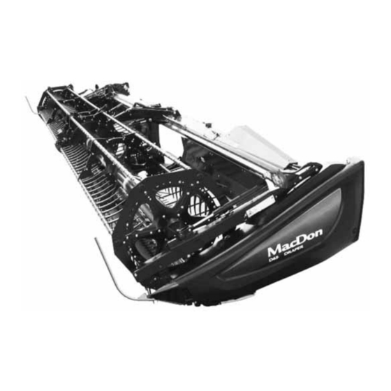
MacDon D65 Operator's Manual
Draper header for self-propelled windrowers
Hide thumbs
Also See for D65:
- Operator's manual (310 pages) ,
- Assembly instruction manual (110 pages) ,
- Installation instructions manual (74 pages)

Related Manuals for MacDon D65


Summary of Contents for MacDon D65
- Page 1 Draper Header for Self-Propelled Windrowers IMPORTANT: PAGE 35 HAS BEEN UPDATED SINCE THIS MANUAL WAS PUBLISHED. Operator’s Manual 169899 Revision A Original Instruction The harvesting specialists.
- Page 2 D65 Draper Header for Self-Propelled Windrowers Published: August, 2014...
- Page 3 Declaration of Conformity 169899 Revision A...
- Page 4 Introduction This instructional manual contains information on the D65 Draper Header. It is designed to serve a dual function in your grain, hay, and specialty crop harvesting operation. Teamed with your self-propelled windrower power unit and optional hay conditioner, D65 Draper Headers will cut and lay crop into uniform, fluffy windrows.
- Page 5 List of Revisions The following lists the changes from the previous version (169594 Revision C) of this document. Summary of Change Refer To Document Number revised. List of Revisions added. Timed Knife Drive Tensioning revised. Tensioning Timed Knife Drive Belts, page 168 Knife Drive Belt Tracking added.
-
Page 6: Model And Serial Number
Model and Serial Number Record the model number, serial number, and model year of the header and Slow Speed Transport/Stabilizer Wheel option (if installed) on the lines below. NOTE: Right Hand (RH) and Left Hand (LH) designations are determined from the operator’s position, facing forward. Draper Header Header Model: Serial Number:... -
Page 7: Table Of Contents
TABLE OF CONTENTS Declaration of Conformity ........................i Introduction ............................ii List of Revisions ..........................iii Model and Serial Number.........................iv Safety ..............................1 Safety Alert Symbols........................1 Signal Words........................... 2 General Safety ..........................3 Maintenance Safety ......................... 6 Hydraulic Safety ..........................7 Tire Safety............................ - Page 8 TABLE OF CONTENTS 4.7.9 Reel Fore-Aft Position ......................58 Adjusting Reel Fore-Aft Position ..................59 Repositioning Fore-Aft Cylinders on Single Reel ............... 59 Repositioning Fore-Aft Cylinders on Double Reel.............. 62 4.7.10 Reel Tine Pitch........................65 Choosing a Reel Cam Setting..................65 Adjusting Reel Cam ......................
- Page 9 TABLE OF CONTENTS Maintenance and Servicing ........................113 Preparation for Servicing ....................... 113 Maintenance Specifications ......................114 6.2.1 Conversion Chart ........................114 6.2.2 Recommended Fluids and Lubricants ..................115 6.2.3 Torque Specifications ......................115 SAE Bolt Torque Specifications..................115 Metric Bolt Specifications ....................117 Metric Bolt Specifications Bolting into Cast Aluminum ............120 Flare-Type Hydraulic Fittings ..................120 O-Ring Boss (ORB) Hydraulic Fittings (Adjustable) ............122...
- Page 10 TABLE OF CONTENTS 6.7.1 Removing Drapers ........................176 6.7.2 Installing Drapers ........................176 6.7.3 Adjusting Draper Tension .......................178 6.7.4 Removing Endless Draper .....................180 6.7.5 Installing Endless Draper .......................183 6.7.6 Adjusting Header Draper Tracking ..................184 6.7.7 Adjusting Deck Height ......................186 6.7.8 Draper Roller Maintenance ....................188 Inspecting Draper Roller Bearing ..................188 Draper Deck Idler Roller ....................188 Draper Drive Roller ......................191...
- Page 11 TABLE OF CONTENTS Installing Reel Drive Motor....................231 Installing Drive Sprocket....................232 Tightening Drive Chain ....................232 Installing Drive Cover .....................233 6.9.4 Replacing Drive Chain on Double Reel ...................233 Removing Drive Cover ....................234 Loosening Drive Chain ....................234 Disconnecting the Reel Drive Method................234 Breaking the Chain Method ....................236 Tightening Drive Chain ....................237 Installing Drive Cover .....................237 6.9.5...
- Page 12 TABLE OF CONTENTS 8.4.6 End Swath Deflector Rods (End Delivery) ................266 8.4.7 HC10 Hay Conditioner......................267 8.4.8 Hydraulic Deck Shift Package ....................267 8.4.9 Swath Forming Rods (Center Delivery) ...................267 8.4.10 Upper Cross Auger (UCA) .....................268 8.4.11 Upper Cross Auger Hydraulic Kit for DDD ................268 8.4.12 Upper Cross Auger Case Drain Kit for SDD ................268 8.4.13...
-
Page 13: Safety
1 Safety 1.1 Safety Alert Symbols This safety alert symbol indicates important safety messages in this manual and on safety signs on the header. This symbol means: • ATTENTION! • BECOME ALERT! • YOUR SAFETY IS INVOLVED! Carefully read follow safety message accompanying this symbol. -
Page 14: Signal Words
SAFETY 1.2 Signal Words Three signal words, DANGER, WARNING, and CAUTION, are used to alert you to hazardous situations. The appropriate signal word for each situation has been selected using the following guidelines: DANGER Indicates an imminently hazardous situation that, if not avoided, will result in death or serious injury. WARNING Indicates a potentially hazardous situation that, if not avoided, could result in death or serious injury. -
Page 15: General Safety
SAFETY 1.3 General Safety CAUTION The following are general farm safety precautions that should be part of your operating procedure for all types of machinery. Protect yourself • When assembling, operating, and servicing machinery, wear all the protective clothing and personal safety devices that COULD be necessary for the job at hand. - Page 16 SAFETY • Provide a first aid kit for use in case of emergencies. • Keep a fire extinguisher on the machine. Be sure the fire extinguisher is properly maintained. Be familiar with its proper use. • Keep young children away from the machinery at all times.
- Page 17 SAFETY • Keep the area used for servicing machinery clean and dry. Wet or oily floors are slippery. Wet spots can be dangerous when working with electrical equipment. Be sure all electrical outlets and tools are properly grounded. • Keep work area well lit. •...
-
Page 18: Maintenance Safety
SAFETY 1.4 Maintenance Safety To ensure your safety while maintaining the machine: • Review the operator’s manual and all safety items before operation and/or maintenance of the machine. • Place all controls in Neutral, stop the engine, set the park brake, remove the ignition key, and wait for all moving parts to stop before servicing, adjusting, and/or repairing. -
Page 19: Hydraulic Safety
SAFETY 1.5 Hydraulic Safety • Always place hydraulic controls Neutral before dismounting. • Make sure that all components in the hydraulic system are kept clean and in good condition. • Replace any worn, cut, abraded, flattened, or crimped hoses and steel lines. •... -
Page 20: Tire Safety
SAFETY 1.6 Tire Safety • Follow proper procedures when mounting a tire on a wheel or rim. Failure to do so can produce an explosion that may result in serious injury or death. Figure 1.14: Over-Inflated Tire • Do NOT attempt to mount a tire unless you have the proper training and equipment. -
Page 21: Safety Signs
SAFETY 1.7 Safety Signs • Keep safety signs clean and legible at all times. • Replace safety signs that missing become illegible. • If original parts on which a safety sign was installed are replaced, be sure the repair part also bears the current safety sign. -
Page 22: Safety Decal Locations
SAFETY 1.8 Safety Decal Locations Figure 1.17: Upper Cross Auger A - MD #174682 Figure 1.18: Slow Speed Transport A - MD #220799 169899 Revision A... - Page 23 SAFETY Figure 1.19: Slow Speed Transport Tow-Bar A - MD #220797 B - MD #220798 Figure 1.20: Vertical Knife A - MD #174684 169899 Revision A...
- Page 24 SAFETY Figure 1.21: Endsheets, Reel Arms, Backsheet A - MD #131393 B - MD #174632 C - MD #184371 D - MD #184371 (DK Only) E - MD #131392 (2 Places) F - MD #131391 (2 Places) G - MD #174436 H - MD #184371 (DK 2 Places) 169899 Revision A...
- Page 25 SAFETY Figure 1.22: Back Tube: 15-Foot Header A - MD #184422 B - MD #184372 C - MD #131391 169899 Revision A...
- Page 26 SAFETY Figure 1.23: Back Tube: 20-Foot Header A - MD #184372 B - MD #166466 C - MD #131391 169899 Revision A...
- Page 27 SAFETY Figure 1.24: Back Tube: 25-Foot Header A - MD #184372 B - MD #166466 C - MD #131391 169899 Revision A...
- Page 28 SAFETY Figure 1.25: Back Tube: 30-, 35-, 40-Foot Header A - MD #184372 B - MD #166466 C - MD #131391 D - MD #131392 (30 & 35 Ft. DR Only) E - MD #184372 (Split Frame) 169899 Revision A...
-
Page 29: Interpreting Safety Signs
SAFETY 1.9 Interpreting Safety Signs In the safety sign explanations below, (a) refers to the top or left position panel, (b) refers to the bottom or right position of the safety decal depending on decal orientation. NOTE: If there are more than two panels in a decal, the lettering will continue downward or to the right, depending on decal orientation. - Page 30 SAFETY 2. MD #131391 a. Crushing hazard b. DANGER • Rest header on ground or engage safety props before going under unit Figure 1.27: MD #131391 3. MD #131392 a. Crushing hazard b. WARNING • To avoid injury from fall of raised reel; fully raise reel, stop the engine, remove the key, and engage safety prop on each reel support arm before working on or under reel.
- Page 31 SAFETY 5. MD #166466 a. High pressure oil hazard b. WARNING Do not go near leaks. • High pressure oil easily punctures skin causing serious injury, gangrene, or death. • If injured, seek emergency medical help. Immediate surgery is required to remove oil. •...
- Page 32 SAFETY 8. MD #174682 a. Auger entanglement hazard b. CAUTION • To avoid injury from entanglement with rotating auger, stand clear of header while machine is running. Figure 1.33: MD #174682 9. MD #174684 a. Sharp component hazard b. CAUTION •...
- Page 33 SAFETY 10. MD #184372 a. General hazard pertaining to machine operation and servicing b. CAUTION To avoid injury or death from improper or unsafe machine operation: • Read the operator’s manual and follow all safety instructions. If you do not have a manual, obtain one from your Dealer.
- Page 34 SAFETY 12. MD #193147 a. Transport/roading hazard b. WARNING • Ensure tow-bar lock mechanism is locked Figure 1.37: MD #193147 13. MD #220797 a. Tipping hazard in transport mode b. WARNING • Read operator’s manual more information on potential tipping or roll-over of header while transporting.
- Page 35 SAFETY 15. MD #220799 a. Transport/roading hazard b. WARNING • Ensure tow-bar lock mechanism is locked Figure 1.40: MD #220799 169899 Revision A...
-
Page 37: Reference
A hydraulic cylinder link between the header and the machine to which it is attached: Center-link It is used to change header angle CGVW Combined vehicle gross weight D-Series header MacDon rigid draper header Double knife Double-knife drive Double-draper drive Double reel Finger tight is a reference position where sealing surfaces or components are Finger tight making contact with each other and the fitting has been tightened to a point where... - Page 38 REFERENCE Term Definition National Pipe Thread: a style of fitting used for low pressure port openings. Threads on NPT fittings are uniquely tapered for an interference fit O-ring boss: a style of fitting commonly used in port opening on manifolds, pumps and motors O-ring face seal: a style of fitting commonly used for connecting hoses and tubes.
-
Page 39: Component Identification
REFERENCE 2.2 Component Identification Figure 2.1: D65 Windrower Header Components A - Reel Cam B - Pick-Up Reel Tines C - Drapers D - Center Reel Arm Prop Handle E - Hydraulic Connections F - Transport Light G - Reel Safety Prop... -
Page 41: Specifications
3 Specifications | D65 | Attachments S: standard / O : optional (factory installed) / O : optional (dealer installed) / -: not available CUTTERBAR Effective cutting width (distance between crop divider points) 15 ft. header 15.00 ft. (180 in. [4572 mm]) 20 ft. - Page 42 SPECIFICATIONS Guard: Pointed / Forged / Double Heat Treated (DHT) Hold-Down: Sheet Metal / Adjustment bolt Guard: Pointed / Forged / Case Hardened (CH) Hold-Down: Sheet Metal / Adjustment Bolt Guard: Stub / Forged Bottom / Forged Top / Adjustment Plate Guard: Stub / Forged Bottom / Sheet Metal Top / Adjustment Bolt Guard: 4 Point / No-choke Design (2 Long Points with Tangs / 2 Short Points without Tangs) Guard Angle (cutterbar on ground)
- Page 43 SPECIFICATIONS Header Width (Field Mode) Cut Width + 15-1/8 in. (384 mm) (Long Dividers 104 in. (2636 mm) Installed) Header Only (Long Dividers 97 in. (2452 mm) Header Width (Transport Removed) Mode—Reel Fore-Aft (Long Dividers With Fully Retracted) 112 in. (2834 mm) Installed) HC10 Hay Conditioner...
- Page 44 SPECIFICATIONS ATTACHMENTS HC10 Hay Conditioner Roll Length 72 in. (1830 mm) Outside Diameter 9-1/8 in. (232 mm) Roll Tube Diameter 6-5/8 in. (168 mm) Roll Speed 847–915 rpm Upper Cross Auger Outside Diameter 12 in. (305 mm) All sizes except 25 ft. 6 in.
-
Page 45: Operation
• It is your responsibility to read and understand this manual completely before operating the header. Contact your MacDon Dealer if an instruction is not clear to you. • Follow all safety messages in the manual and on safety decals on the machine. -
Page 46: Operational Safety
OPERATION 4.2 Operational Safety CAUTION Follow these safety precautions: • Follow all safety and operational instructions given in your operator’s manuals. If you do not have a windrower manual, get one from your Dealer and read it thoroughly. • Never attempt to start the engine or operate the machine except from the windrower seat. -
Page 47: Reel Safety Props
OPERATION DANGER To avoid bodily injury or death from unexpected start-up or fall of raised machine, always stop engine, remove key, and engage safety props before going under header for any reason. Refer to the windrower operator’s manual for instructions regarding the proper use and storage of header safety props. 4.2.2 Reel Safety Props WARNING To avoid bodily injury from fall of raised reel, always engage reel safety props before going under raised... -
Page 48: Disengaging Reel Safety Props
OPERATION 3. At the center reel arm on double reel headers, use handle (A) to move lock rod to inboard position (B), engaging pin (C) under prop. 4. Lower reel until safety props contact cylinder mounts on outer reel arms and pin at center arm. Figure 4.4: Center Arm Reel Prop Disengaging Reel Safety Props 1. -
Page 49: Endshields
OPERATION 3. Use handle (B) to move lock rod (A) to outboard position. Figure 4.6: Center Arm Safety Prop 4.2.3 Endshields A hinged, polyethylene endshield is fitted on each end of the header. Opening Endshields To open an endshield, follow these steps. 1. -
Page 50: Closing Endshields
OPERATION 2. Use tool (B) to unlock latch (A) at lower rear corner of endshield. 3. Lift shield at aft end to clear pin at top rear of endshield. 4. Swing shield out and away from header while maintaining forward pressure to prevent shield from slipping out of tab (C) at front of endsheet. -
Page 51: Removing Endshields
OPERATION 3. Push in shield to engage lower latch (A). 4. Use tool (B) to lock lower latch (A). Figure 4.11: Endshield 5. Replace tool (B) and lynch pin (A) on top pin (C). Figure 4.12: Endshield Pin Removing Endshields To remove an endshield, follow these steps: 1. -
Page 52: Installing Endshields
OPERATION Installing Endshields To install an endshield, follow these steps. 1. Position endshield on support (A) and align the hole in the endshield with stud (B) on the support. Figure 4.14: Endshield 2. Secure endshield to the support with acorn nut (A). 3. -
Page 53: Adjusting Endshields
OPERATION Adjusting Endshields Plastic endshields are subject to expansion or contraction from large temperature variations. The position of the top pin and lower catch can be adjusted to compensate for dimensional changes. To adjust the endshield, perform the following: 1. Check gap ‘X’ between the front end of shield and header frame and compare to chart. -
Page 54: Daily Start-Up Check
OPERATION 4.2.4 Daily Start-Up Check CAUTION • Clear the area of other persons, pets, etc. Keep children away from machinery. Walk around the machine to be sure no one is under, on, or close to it. • Wear close-fitting clothing and protective shoes with slip-resistant soles. -
Page 55: Break-In Period
OPERATION 4.3 Break-in Period NOTE: Until you become familiar with the sound and feel of your new header, be extra alert and attentive. After attaching the header to the windrower for the first time, follow these steps: 1. Operate the machine with reel drapers and knife running slowly for five minutes, watching and listening FROM THE OPERATOR’S SEAT for binding or interfering parts. -
Page 56: Shutdown Procedure
OPERATION 4.4 Shutdown Procedure CAUTION To shut down and before leaving the windrower seat for any reason, follow these steps: • Park on level ground if possible. • Lower the header fully. • Place all controls in NEUTRAL or PARK. •... -
Page 57: Cab Controls
OPERATION 4.5 Cab Controls CAUTION Be sure all bystanders are clear of machine before starting engine or engaging any header drives. Refer to your windrower operator’s manual for identification of in-cab controls for: • Header engage/disengage control • Header height •... -
Page 58: Header Setup
4.6.2 Header Settings This table is a guideline for setting up the D65 Draper Header. Settings other than those suggested can be made to suit various crops and conditions not covered here. - Page 59 OPERATION Stubble Reel Skid Upper Float Divider Header Reel Reel Crop Height Crop Knife Stabilizer Speed Shoe Cross Type Condition Rods Angle Speed Position Wheels Position Auger (mm) Light Medium 5–10 Down 6 or 7 Middle or Required Normal 4–8 70–100 Down (102–...
-
Page 60: Reel Settings
Refer to 4.6.2 Header Settings, page 46 for applicability of each finger pattern and reel position. Table 4.2 D65 Reel Settings Chart Cam Setting Number Reel Position Reel Finger Pattern... - Page 61 OPERATION Cam Setting Number Reel Position Reel Finger Pattern (Finger Speed Gain) Number 3 (30%) 6 or 7 4 (35%) 2 or 3 NOTE: • Adjust reel forward to get closer to ground when tilting header back. Fingers/tines will dig into ground at extreme reel forward positions, so adjust skid shoes or header angle to compensate.
-
Page 62: Header Operating Variables
OPERATION 4.7 Header Operating Variables Satisfactory function of the header in all situations requires making proper adjustments to suit various crops and conditions. Correct operation reduces crop loss and allows cutting of more acres. As well, proper adjustments and timely maintenance will increase the length of service you receive from the machine. - Page 63 OPERATION 3. On the right wheel assembly, remove hairpin (A) from latch. 4. Disengage latch (B) and lift right wheel out of hook and place on ground as shown. This reduces weight of assembly and makes adjusting wheel position easier. 5.
- Page 64 OPERATION IMPORTANT: Continuous operation with excessive spring compression (i.e., load Indicator reading greater than ‘4’ or a compressed length (A) less than 11–5/8 in. [295 mm]) can result in damage to suspension system. 14. Adjust header angle to desired working angle with the machine’s header angle controls.
-
Page 65: Cutting On The Ground
OPERATION 6. Lower header to desired cutting height using combine controls and check load indicator. As an example the image shows that the wheels are set to a range between ‘2’ and ‘3’ on load indicator. Figure 4.24: Load Indicator IMPORTANT: Continuous operation with excessive spring compression (i.e., load Indicator reading greater than ‘4’... - Page 66 OPERATION Adjusting Inner Skid Shoe 1. Fully raise the stabilizer wheels or slow speed transport wheels (if installed). Refer to: • Adjusting Stabilizer Wheels, page 52, or • Adjusting Stabilizer/Slow Speed Transport Wheels, page 50 DANGER To avoid bodily injury or death from unexpected start-up or fall of raised machine, always stop engine, remove key, and engage safety props before going under header for any reason.
-
Page 67: Header Float
Figure 4.28: Outer Skid Shoe 4.7.2 Header Float D65 windrower headers are designed to ride on the skid shoes for cutting on the ground operation. The windrower float system reduces the ground pressure so that the header floats over obstacles and follows ground contours instead of being supported by the windrower lift cylinders. -
Page 68: Controlling Header Angle
Refer to the following table and contact your MacDon dealer for ordering information. -
Page 69: Ground Speed
OPERATION 4.7.5 Ground Speed Using the proper ground speed will result in cleanly cut crop and even delivery of material for a good windrow. Refer to 4.10 Windrow Types, page 79 for effects of ground speed on windrow formation. Reduce ground speed in difficult cutting conditions to reduce loads on cutting components and drives. Use lower ground speeds in very light crops (for example, short soybeans), to allow the reel to pull in short plants. -
Page 70: Knife Speed
OPERATION 4.7.7 Knife Speed The header knife drive is driven by the windrower hydraulic pump and is controlled with the windrower Cab Display Module (CDM). The default speed is 1200 strokes per minute (spm). Refer to your windrower operator’s manual. Table 4.3 Knife Speed Guidelines Recommended Knife Speed Range (spm) Header Size (ft.) -
Page 71: Adjusting Reel Fore-Aft Position
OPERATION A decal (A) is provided on the reel right support arm for identifying reel position. The cam disc aft edge (B) is the gauge indicator. For straight standing crop, center the reel over the cutterbar (4–5 on decal). For crops that are down, tangled, or leaning, it may be necessary to move the reel ahead of the cutterbar (lower number on decal). - Page 72 OPERATION Reposition right arm cylinder as follows: NOTE: Reel components are not shown for clarity. 1. Position reel fully aft with support arms horizontal. 2. Stop engine and remove key. 3. Remove four bolts (A) securing cylinder bracket (B) to reel arm.
- Page 73 OPERATION Reposition left arm cylinder as follows: NOTE: Reel components are not shown for clarity. 6. Remove pin (A) securing cylinder (B) to bracket/light assembly (C). 7. Remove bolts (D) securing bracket (C) to reel arm and remove bracket/light assembly. 8.
-
Page 74: Repositioning Fore-Aft Cylinders On Double Reel
OPERATION Repositioning Fore-Aft Cylinders on Double Reel The reel can be moved approximately 9 in (227 mm) further aft by repositioning the fore-aft cylinders on the reel arms. To reposition the cylinders on a double reel, follow these steps: WARNING Stop windrower engine and remove key before making adjustments to machine. - Page 75 OPERATION Reposition right arm cylinder as follows: NOTE: Reel components are not shown for clarity. 6. Remove four bolts (A) securing cylinder bracket (B) to reel arm. 7. Push reel back until bracket (B) lines up with the aft set of holes (C).
- Page 76 OPERATION Reposition left arm cylinder as follows: NOTE: Reel components are not shown for clarity. 9. Remove pin (A) securing cylinder (B) to bracket/light assembly (C). 10. Remove bolts (D) securing bracket (C) to reel arm and remove bracket/light assembly. 11.
-
Page 77: Reel Tine Pitch
OPERATION 4.7.10 Reel Tine Pitch IMPORTANT: The following describes the concept and operational guidelines of the pick-up reel. Please read carefully before operating the machine. The pick-up reel is designed to pick up flattened and severely lodged crops. It is not always necessary to increase the tine pitch (higher cam setting) to pick up crops that are lodged, but rather, the cam settings are mainly used to determine how the crop will get delivered to the drapers. - Page 78 OPERATION Cam Position 2, Reel Position 3 or 4 is the recommended starting position for most crops and conditions. • This setting gives a fingertip speed approximately 20% faster than the reel speed. • If crops tend to stall on the cutterbar with the reel in a forward position, the cam setting should be increased to push the crop past the rear edge of the cutterbar.
-
Page 79: Adjusting Reel Cam
OPERATION Cam Position 4, Header Angle At Maximum, and Reel Fully Forward provides the maximum amount of reel reach below the cutterbar to pick up lodged crops and gives a finger tip speed approximately 35% faster than the reel speed. •... -
Page 80: Crop Dividers
OPERATION 4.7.11 Crop Dividers Crop dividers are used to help divide the crop when harvesting. They are removable to allow installation of vertical knives and to decrease transport width. Removing Crop Dividers from Header with Latch Option To remove crop dividers from a header with the latch option, follow these steps. DANGER To avoid bodily injury or death from unexpected start-up or fall of raised machine, always stop engine, remove key, and engage safety props before going under header for any reason. -
Page 81: Removing Crop Dividers From Header Without Latch Option
OPERATION Removing Crop Dividers from Header without Latch Option To remove crop dividers from a header without the latch option, follow these steps. DANGER To avoid bodily injury or death from unexpected start-up or fall of raised machine, always stop engine, remove key, and engage safety props before going under header for any reason. - Page 82 OPERATION 3. At divider storage location, lift divider to disengage lugs (A) at lower end and then lower it slightly to disengage pin (B) from endsheet. Figure 4.51: Stored Crop Divider 4. Position crop divider as shown by locating lugs (A) in holes in endsheet.
-
Page 83: Installing Crop Dividers On Header Without Latch Option
OPERATION 7. Check that divider does NOT move laterally. Adjust bolts (A) as required to tighten divider and remove lateral play when pulling at divider tip. 8. Close/install endshields. Figure 4.53: Crop Divider Installing Crop Dividers on Header without Latch Option To install crop dividers on a header without the latch option, follow these steps. -
Page 84: Crop Divider Rods
OPERATION 5. Lift forward end of divider and install bolt (A) and special stepped washer (B) (step towards divider). Tighten bolt. 6. Check that divider does not move laterally. Adjust bolts (C) as required to tighten divider and remove lateral play when pulling at divider tip. -
Page 85: Removing Crop Divider Rods
OPERATION Removing Crop Divider Rods To remove divider rods, follow these steps: 1. Loosen bolt (B) and remove rod (A). Figure 4.56: Crop Divider Rod 2. Store both rods on the inboard side of the right endsheet. Figure 4.57: Stored Divider Rod Using Rice Dividers Optional special rice dividers can be installed and used when required. -
Page 86: Delivery Opening
OPERATION 4.8 Delivery Opening The width and location of the delivery opening affects the width and configuration of the windrow. The decision to widen or narrow the center delivery opening, or to double windrow, should be based on the following factors: •... -
Page 87: Adjusting Delivery Opening On Header With Hydraulic Deck Shift
OPERATION 4.8.2 Adjusting Delivery Opening on Header with Hydraulic Deck Shift The delivery opening can be changed by moving the inboard deck shift stops. 1. Remove bolts (A). 2. Slide stop (B) outboard to decrease the maximum opening size, inboard increase maximum opening. -
Page 88: Double Windrowing
Double windrowing is laying two swaths side-by-side. Larger capacity combines or forage harvesters can then pick up twice as much material in a single pass, saving time and fuel. Double windrowing is performed with the D65 Draper Headers by two methods; deck shifting, or using the Double Windrow Attachment (DWA). -
Page 89: Shifting Decks Manually
OPERATION 4.9.2 Shifting Decks Manually Both decks can be moved manually to deliver the crop from the center or right/left end on 25 to 40 ft. headers. To deliver crop from the right end, move the decks to the left end of the header: CAUTION Stop engine and remove key from ignition before leaving operator's seat for any reason. -
Page 90: Using Double Windrow Attachment (Dwa)
OPERATION Laying a Double Windrow NOTE: 30 ft. headers equipped with transport or stabilizer system, require that the wheels be in the raised position to avoid interfering with the windrow. 4. Position decks at the left end of header to deliver crop from right end (A). -
Page 91: Windrow Types
OPERATION 4.10 Windrow Types There are three basic criteria by which the quality of a windrow is measured: • Weight Distribution: Heads and stalks distributed evenly across full width of windrow • Good Curing: A loose, open windrow for better drying •... - Page 92 OPERATION Machine Weight Windrow Type Description Curing Weatherability Setting Distribution Guidelines 45° Diagonal The stalks are Poor Fair Poor • Low reel lined along one speed edge and heads are along opposite • Less edge, 45° to windrow aggressive perpendicular. This tine pitch windrow can be •...
-
Page 93: Haying Tips
OPERATION 4.11 Haying Tips The following information may be useful when using the D65 Draper Header in hay crops. 4.11.1 Curing A quick cure will maintain top quality because • 5% of the protein is lost for each day hay lies on the ground. -
Page 94: Driving On Windrow
OPERATION Configuration Advantage High and fluffy Movement of air through the windrow is more important to the curing process than is direct sunlight. Consistent formation, not bunchy Permits an even flow of material into the baler, chopper, etc. and allows for more even drying. Even distribution of material across windrow Results in even and consistent bales to minimize handling and stacking problems. -
Page 95: Levelling The Header
OPERATION 4.12 Levelling the Header The windrower linkages are factory-set to provide the proper level for the header and should not normally require adjustment. NOTE: The float springs are NOT used to level the header. If the header is not level, check the pressure of the windrower’s tires to ensure they are properly inflated (refer to your windrower’s operator’s manual). -
Page 96: Unplugging Cutterbar
OPERATION 4.13 Unplugging Cutterbar To remove plugged material from the cutterbar, follow these steps. 1. Stop forward movement of machine and disengage header drives. 2. Raise header to prevent it from filling with dirt, and engage header drive clutch. CAUTION Lowering rotating reel on a plugged cutterbar will damage the reel components. -
Page 97: Upper Cross Auger (Uca)
IMPORTANT: The upper cross auger drive motor must be equipped with a case drain kit when used on single draper drive headers. See your MacDon Dealer for details. Figure 4.66: Upper Cross Auger 4.14.1 Removing Beater Bars To remove beater bars, follow these steps. - Page 98 OPERATION 2. Remove bolts (A) securing bars (B) and clamps (C) to auger tubes, and remove bars and clamps. Figure 4.67: Single Reel Headers Figure 4.68: Beater Bars 169899 Revision A...
-
Page 99: Installing Beater Bars
OPERATION 4.14.2 Installing Beater Bars To install beater bars, follow these steps. 1. Locate one beater bar (B) with one clamp set (C) on auger tube and loosely secure with carriage bolt (A) and nut. Bolt head MUST face direction of auger rotation. -
Page 100: Transporting Header
• Travel speed should be such that complete control and machine stability are maintained at all times. 4.15.2 Towing Headers with the Slow Speed Transport/Stabilizer Wheel option can be towed behind a properly configured MacDon windrower or an agricultural tractor. Refer to the windrower operator’s manual for instructions. -
Page 101: Attaching Header To Towing Vehicle
• Connect header wiring harness 7-pole plug to mating receptacle on towing vehicle. (The 7-pole receptacle is available from your MacDon Dealer parts department). • Ensure lights are functioning properly and clean the slow moving vehicle emblem and other reflectors. -
Page 102: Converting From Transport To Field Position
OPERATION 4.15.3 Converting from Transport to Field Position To convert the header from Transport to Field position, follow these steps. Removing Tow-Bar Remove tow-bar as follows: 1. Block the tires to prevent header rolling, and unhook from towing vehicle. 2. Disconnect wiring connector (A) on tow-bar. 3. -
Page 103: Storing Tow-Bar
OPERATION 5. Remove clevis aside later installation. 6. Push latch (B) and lift tow-bar (C) from hook. Release latch. 7. Reinstall clevis pin. Figure 4.73: Tow-Bar Latch Storing Tow-Bar Store tow-bar as follows: 1. At the left end of the header, place the inner end of the outer half of the tow-bar in cradle (A) on header backtube. - Page 104 OPERATION 4. At the right end of the 25, 35, and 40 ft. header: a. Place the inner end of the inner half of the tow-bar in cradle (A) on header backtube. b. Secure tube end in support (B) with clevis pin (C). Secure with hairpin.
-
Page 105: Moving Front (Left) Wheels Into Field Position
OPERATION 6. Attach header to windrower. Refer to windrower operator’s manual for instructions. IMPORTANT: Carrying the tow-bar on the header will affect the main header float. Refer to your windrower operator’s manual for adjustment procedures. 7. Place transport wheels into field position. Refer to: •... -
Page 106: Moving Rear (Right) Wheels Into Field Position
OPERATION 5. Align lift hook (A) with lug (B) and lift wheel assembly to engage pin in hook (A). Ensure latch (C) is engaged. 6. Install clevis pin (D) and secure with hairpin to center of axle. Figure 4.78: Front (Left) Wheels 7. - Page 107 OPERATION 2. Remove pin (A) and store at (B). 3. Pull handle (C) up to release. 4. Lift wheel to desired height and engage support channel into slot (D) in vertical support. 5. Push down on handle (C) to lock. Figure 4.81: Left Rear Wheel 6.
-
Page 108: Converting From Field To Transport Position
OPERATION 9. Pull right wheel, swivel wheel counterclockwise to position shown and lock with pin (A). 10. Remove hairpin (B) from latch (C). 11. Lift wheel, lift latch (C), and engage lug (D) onto left axle. Ensure latch closes. 12. Secure latch with hairpin (B), with open end of pin facing rear of combine. - Page 109 OPERATION CAUTION Stand clear of wheels and release linkage carefully as wheels will drop once the mechanism is released. 1. Pull handle (B) up to release and raise the linkage (A) fully upward in the vertical support. 2. Raise header fully, stop engine, and remove key from ignition.
-
Page 110: Moving Rear (Right) Wheels Into Transport Position
OPERATION 7. Remove pin (A) from storage at top of leg (B). 8. Move and swivel wheels clockwise so that connector (C) is turned towards the front end of the header. 9. Insert pin (A) and turn to lock. 10. Lower header so that left wheels are just touching the ground. - Page 111 OPERATION 1. Remove hairpin (A) from latch (B). 2. Lift latch (B), disengage right axle (C), and lower to ground. CAUTION Stand clear of wheels and release linkage carefully as wheels will drop once the mechanism is released. 3. Carefully pull handle (D) to release the spring and let the wheel drop to the ground.
- Page 112 OPERATION 8. Left wheel is now in Transport position as shown. Figure 4.91: Transport Position 9. Pull pin (A), and swivel wheel (B) clockwise 90 degrees. Figure 4.92: Right Rear Wheel 10. Lock wheel (A) with pin (B). Move the right axle (C) to front of header.
-
Page 113: Attaching Tow-Bar
OPERATION 11. Remove pin (A), raise support (B) to position shown, and reinsert pin (A). IMPORTANT: Ensure pin (A) engages the tube on the axle. 12. Swing brace (C) into position as shown and insert brace into slot (D) behind cutterbar. Position brace so that pin (E) engages hole in bracket (F). - Page 114 OPERATION 5. At left side of the header, unhook rubber strap (D) on cradle (A). 6. Remove hitch pin (C) from support (B), and remove tow-bar. 7. Install rubber strap (D) on cradle (A). Figure 4.96: Removing Tow-Bar 8. Connect the outer half (B) of the tow-bar to the inner half (A).
- Page 115 OPERATION 9. Lift the outer half (B) and insert it into the inner half (A) Figure 4.98: Assembling Tow-Bar 10. Secure the two halves together with L-pin (A), then turn to lock. Secure pin with ring (B). 11. Connect electrical harness to connector (C). Figure 4.99: Assembling Tow-Bar 12.
- Page 116 OPERATION 15. Make the electrical connection (A) at the front wheel. Figure 4.101: Connecting Harness 169899 Revision A...
-
Page 117: Storage
Oil knife components to prevent rust. 8. Check for worn or broken components, and repair or order replacements from your MacDon Dealer. Attention to these items right away will save time and effort at beginning of next season. -
Page 119: Header Attachment/Detachment
5 Header Attachment/Detachment This chapter includes instructions on setting up, attaching, and detaching the header. 5.1 Attaching Header to Windrower Refer your windrower operator’s manual procedures to mechanically attach the header to the self-propelled windrower. Refer to the following procedures for electrical and hydraulic connections. - Page 120 HEADER ATTACHMENT/DETACHMENT 5. Push hose connectors onto mating receptacle until collar on receptacle snaps into lock position. 6. Remove cover on electrical receptacle (A). 7. Push electrical connector onto receptacle and turn collar on connector to lock it in. 8. Attach cover to mating cover on tractor wiring. Figure 5.3: Header Receptacles A - Electrical Connector B - Knife Drive...
- Page 121 HEADER ATTACHMENT/DETACHMENT 11. Open cover on header receptacle (A). 12. Push in lock button (B) and pull handle (C) to half open position. Figure 5.6: Reel Hydraulics Receptacle 13. Remove hose bundle with multi-coupler (C) from windrower, locate onto header receptacle and push handle (B) to engage pins on connector.
-
Page 122: Detaching Header From Windrower
HEADER ATTACHMENT/DETACHMENT 5.2 Detaching Header from Windrower To detach the header from the windrower, follow these steps: 1. Fully lower the reel. 2. To disconnect the reel hydraulics, push in lock button (A) and pull handle (B) to disengage multi-coupler (C) from header receptacle. 3. - Page 123 HEADER ATTACHMENT/DETACHMENT 7. To disconnect hoses from header, line up slot (A) in collar with pin (B) on connector. 8. Push collar toward pin and pull connector to disengage. 9. Install caps on connectors and hose ends (if equipped). Figure 5.11: Quick Disconnect 10.
-
Page 125: Maintenance And Servicing
The following instructions are provided to assist Operator in the use of header. Detailed maintenance, service, and parts information are contained in the technical manual and parts catalog which are available from your MacDon Dealer. CAUTION To avoid personal injury, before servicing header or opening drive covers: 1. -
Page 126: Maintenance Specifications
MAINTENANCE AND SERVICING 6.2 Maintenance Specifications 6.2.1 Conversion Chart Inch-Pound Units SI Units (Metric) Factor Quantity Unit Name Abbreviation Unit Name Abbreviation Area Acres acres x 0.4047 = Hectares US Gallons Flow x 3.7854 = Liters per Minute L/min per Minute Force Pounds Force x 4.4482 =... -
Page 127: Recommended Fluids And Lubricants
MAINTENANCE AND SERVICING 6.2.2 Recommended Fluids and Lubricants Your machine can operate at top efficiency only if clean lubricants are used. • Use clean containers to handle all lubricants. • Store in an area protected from dust, moisture, and other contaminants. Lubricant Specification Description... - Page 128 MAINTENANCE AND SERVICING Table 6.2 SAE Grade 5 Bolt and Grade 5 Distorted Thread Nut Torque (ft·lbf) Torque (N·m) Nominal (*in·lbf) Size (A) Min. Max. Min. Max. 1/4-20 5/16-18 *149 *164 16.7 18.5 3/8-16 7/16-14 1/2-13 9/16-12 Figure 6.2: Bolt Grades 5/8-11 A - Nominal Size B - SAE-8...
-
Page 129: Metric Bolt Specifications
MAINTENANCE AND SERVICING Table 6.4 SAE Grade 8 Bolt and Grade 8 Free Spinning Nut Torque (ft·lbf) Torque (N·m) Nominal (*in·lbf) Size (A) Min. Max. Min. Max. 1/4-20 *150 *165 16.8 18.6 5/16-18 3/8-16 7/16-14 1/2-13 9/16-12 Figure 6.4: Bolt Grades 5/8-11 A - Nominal Size B - SAE-8... - Page 130 MAINTENANCE AND SERVICING Table 6.6 Metric Class 8.8 Bolts and Class 9 Distorted Thread Nut Torque (ft·lbf) Torque (N·m) Nominal (*in·lbf) Size (A) Min. Max. Min. Max. 3-0.5 3.5-0.6 4-0.7 5-0.8 6-1.0 8-1.25 *167 *185 18.8 20.8 Figure 6.6: Bolt Grades 10-1.5 12-1.75 14-2.0...
- Page 131 MAINTENANCE AND SERVICING Table 6.8 Metric Class 10.9 Bolts and Class 10 Distorted Thread Nut Torque (ft·lbf) Torque (N·m) Nominal (*in·lbf) Size (A) Min. Max. Min. Max. 3-0.5 3.5-0.6 4-0.7 5-0.8 6-1.0 *105 10.7 11.8 8-1.25 Figure 6.8: Bolt Grades 10-1.5 12-1.75 14-2.0...
-
Page 132: Metric Bolt Specifications Bolting Into Cast Aluminum
MAINTENANCE AND SERVICING Metric Bolt Specifications Bolting into Cast Aluminum Table 6.9 Metric Bolt Bolting into Cast Aluminum Bolt Torque Nominal 10.9 Size (A) (Cast Aluminum) (Cast Aluminum) ft·lbf N·m ft·lbf N·m – – – – – – – Figure 6.9: Bolt Grades –... - Page 133 MAINTENANCE AND SERVICING Table 6.10 Flare-Type Hydraulic Tube Fittings Flats from Finger Nut Size Torque Value Tube Size Thread Tight (FFFT) SAE No. across Flats O.D. (in.) Size (in.) (in.) ft·lbf N·m Flats Turns 3/16 7/16 7/16 9/16 5/16 9/16 11/16 1-1/16 1-1/4...
-
Page 134: O-Ring Boss (Orb) Hydraulic Fittings (Adjustable)
MAINTENANCE AND SERVICING O-Ring Boss (ORB) Hydraulic Fittings (Adjustable) 1. Inspect O-ring (A) and seat (B) for dirt or obvious defects. 2. Back off the lock nut (C) as far as possible. Ensure that washer (D) is not loose and is pushed toward the lock nut (C) as far as possible. - Page 135 MAINTENANCE AND SERVICING Table 6.11 O-Ring Boss (ORB) Hydraulic Fittings (Adjustable) Torque Value SAE Dash Size Thread Size (in.) ft·lbf (*in·lbf) N·m 3/8-24 *106–115 12–13 7/16–20 14–15 19–21 1/2–20 15–24 21–33 9/16–18 19–21 26–29 3/4–16 34–37 46–50 7/8–14 55–60 75–82 1-1/16-12 88–97 120–132...
-
Page 136: O-Ring Boss (Orb) Hydraulic Fittings (Non-Adjustable)
MAINTENANCE AND SERVICING O-Ring Boss (ORB) Hydraulic Fittings (Non-Adjustable) 1. Inspect O-ring (A) and seat (B) for dirt or obvious defects. 2. Check that O-ring (A) is NOT on the threads, and adjust if necessary. 3. Apply hydraulic system oil to the O-ring. 4. -
Page 137: O-Ring Face Seal (Orfs) Hydraulic Fittings
MAINTENANCE AND SERVICING O-Ring Face Seal (ORFS) Hydraulic Fittings To tighten O-ring face seal (ORFS) hydraulic fittings, follow these steps: 1. Check components to ensure that the sealing surfaces and fitting threads are free of burrs, nicks, and scratches or any foreign material. Figure 6.14: Hydraulic Fitting 2. -
Page 138: Installing A Roller Chain
MAINTENANCE AND SERVICING Table 6.13 O-Ring Face Seal (ORFS) Hydraulic Fittings Torque Value Thread SAE Dash ft·lbf Size Size (in.) N·m (*in·lbf) Note – – 9/16–18 18–21 25–28 – – Note 11/16-16 29–32 40–44 13/16-16 41–45 55–61 1–14 59–65 80–88 1-3/16-12 85–94 115–127... -
Page 139: Installing A Sealed Bearing
MAINTENANCE AND SERVICING 1. Locate ends of chain on sprocket. 2. Install pin connector (A) into chain, preferably from the sprocket backside. 3. Install connector (B) onto pins. 4. Install spring clip (C) onto front pin (D) with closed end of clip in direction of sprocket rotation. -
Page 140: Maintenance Requirements
MAINTENANCE AND SERVICING 6.3 Maintenance Requirements The following maintenance schedule is a listing of periodic maintenance procedures, organized by service intervals. Regular maintenance is the best insurance against early wear and untimely breakdowns. Following this schedule will increase machine life. For detailed instructions, refer to the specific headings in this section. -
Page 141: Maintenance Schedule/Record
MAINTENANCE AND SERVICING 6.3.1 Maintenance Schedule/Record Copy this page to continue record. Maintenance ▲ - Change - Check - Lubricate Action: Record Hour Meter Reading Date Serviced By FIRST USE, Refer to 6.3.2 Break-In Inspection, page 130 END OF SEASON, Refer to 6.3.4 End of Season Service, page 131 10 HOURS OR DAILY Hydraulic Hoses and... -
Page 142: Break-In Inspection
MAINTENANCE AND SERVICING Maintenance ▲ - Change - Lubricate - Check Action: Record Upper Cross Auger RH Bearing 250 HOURS OR ANNUALLY Draper Seal Upper Cross Auger Center Support and U-Joint Reel Drive U-joint Transport Axle Pivot ... -
Page 143: Preseason/Annual Service
Oil knife components to prevent rust. 9. Check for worn or broken components and repair or order replacement from your MacDon Dealer. Attention to these items right away will save time and effort at beginning of next season. -
Page 144: Checking Hydraulic Hoses And Lines
MAINTENANCE AND SERVICING 6.3.5 Checking Hydraulic Hoses and Lines Check hydraulic hoses and lines daily for signs of leaks. WARNING • Avoid high-pressure fluids. Escaping fluid can penetrate the skin causing serious injury. Relieve pressure before disconnecting hydraulic lines. Tighten all connections before applying pressure. Keep hands and body away from pin holes and nozzles which eject fluids under high pressure. -
Page 145: Service Intervals
MAINTENANCE AND SERVICING Service Intervals Refer to the illustrations on the following pages to identify the various locations that require lubrication and servicing. Illustrations are organized by the frequency of service that is required. IMPORTANT: Unless otherwise specified, use High Temperature Extreme Pressure (EP2) Performance with 1% Maximum Molybdenum Disulphide (NLGI Grade 2) Lithium Base. - Page 146 MAINTENANCE AND SERVICING Figure 6.22: Every 100 Hours A - Knife Drive Box (check oil level with top of knife drive box horizontal) B - Dipstick (level between lower hole and end) C - Upper Cross Auger Bearing (1 PLC) D - Reel Drive Chain (1 PLC) (DR shown –...
- Page 147 MAINTENANCE AND SERVICING Figure 6.23: Every 250 Hours A - Upper Cross Auger U-joint 17 B - Upper Cross Auger Bearing (2 PLCS) 18 17. U-joint has an extended lubrication cross and bearing kit. Stop greasing when greasing becomes difficult or if U-joint stops taking grease.
- Page 148 MAINTENANCE AND SERVICING Figure 6.24: Every 250 Hours (Continued) A - Rear Axle Pivots B - Front Wheel Pivot (1 PLC) D - Double Reel U-Joint (1 PLC) 19 C -Frame/Wheel Pivot (1 PLC) - Both Sides 19. U-joint has an extended lubrication cross and bearing kit. Stop greasing when greasing becomes difficult or if U-joint stops taking grease.
- Page 149 MAINTENANCE AND SERVICING Figure 6.25: Every 500 Hours A - Reel Right Bearing (1 PLC) B - Reel Center Bearing (1 PLC) C - Wheel Bearings (4 PLCS) D - Reel Left Bearing (1 PLC) 169899 Revision A...
-
Page 150: Greasing Procedure
MAINTENANCE AND SERVICING Greasing Procedure Greasing points are marked on the machine by decals showing a grease gun and grease interval in hours of operation. Master grease point location decals as shown below are provided on the header. Use the recommended lubricants specified in this manual. Refer to 6.2.2 Recommended Fluids and Lubricants, page 115. -
Page 151: Electrical
MAINTENANCE AND SERVICING 6.4 Electrical Use electrical tape and wire clips as required to prevent wires from dragging or rubbing. Keep lights clean and replace defective bulbs. 6.4.1 Replacing Light Bulbs To replace a light bulb, follow these steps: 1. Using a Phillips screwdriver, remove screws (A) from fixture and remove plastic lens. -
Page 152: Knife
MAINTENANCE AND SERVICING 6.5 Knife WARNING Keep hands clear of the area between guards and knife at all times. CAUTION To avoid personal injury, before servicing machine or opening drive covers, refer to 6.1 Preparation for Servicing, page 113. CAUTION Wear heavy gloves when working around or handling knives. - Page 153 MAINTENANCE AND SERVICING To replace a section, follow these steps: 1. Stroke knife as required to center the section (A) between guards. 2. Remove nuts (B). 3. Remove bars (C) and lift section off the knife bar. 4. If section is under a splice bar (D), remove the bar. 5.
-
Page 154: Removing Knife
MAINTENANCE AND SERVICING 6.5.2 Removing Knife WARNING Stand to rear of knife during removal to reduce risk of injury from cutting edges. Wear heavy gloves when handling knife. 1. Manually stroke knife to its outer limit and clean area around the knifehead. 2. -
Page 155: Installing Knifehead Bearing
MAINTENANCE AND SERVICING 2. Using a flat-ended tool with approximately the same diameter as pin (A). Tap the seal (B), bearing (C), plug (D), and O-ring (E) from the underside of the knifehead. NOTE: Seal (B) can be replaced without removing the bearing. When changing seal, check pin and needle bearing for wear. -
Page 156: Spare Knife
MAINTENANCE AND SERVICING NOTE: For ease of removing or installing knifehead pin, remove grease zerk from pin. 2. Install knifehead pin (A) through the output arm and into the knifehead. 3. Set groove (B) in knifehead pin 0.06 in. (1.5 mm) above (C). -
Page 157: Adjusting Knife Guards
3. If material is tough to cut, install stub guards with top guard and adjuster plate. A kit is available from your MacDon Dealer. Refer to 8.2.3 Stub Guard Conversion Kit, page 262. -
Page 158: Replacing Pointed Guards On A Double Knife Header
MAINTENANCE AND SERVICING IMPORTANT: The first four outboard guards (B) on drive side(s) of header do not have a ledger plate. Ensure that proper replacement is installed. 5. Install hold-down, and secure with nuts. Tighten nuts to 50 ft·lbf (68 N·m). 6. -
Page 159: Replacing Stub Guards On A Single Knife Header
MAINTENANCE AND SERVICING 3. Position poly wear plate (if applicable), replacement guard (A), adjuster bar, and top guide (B). Install bolts, but do NOT tighten. IMPORTANT: Ensure center guard (A) (right of cutterbar split) has offset cutting surfaces. NOTE: Top guide (B) must accommodate the two overlapping knives at center guard location on double knife header. -
Page 160: Replacing Stub Guards On A Double Knife Header
MAINTENANCE AND SERVICING To replace stub guards, follow these steps: 1. Remove the two nuts (A) and bolts that attach guard (B) and top guide (C) to cutterbar. 2. Remove guard, poly wear plate (if installed), top guide, and adjuster bar (D). 3. -
Page 161: Checking Knife Hold-Downs
MAINTENANCE AND SERVICING 1. Remove the two nuts (A) and bolts that attach guard (B) and top guide (C) and adjuster bar (D) to cutterbar. 2. Remove guard, poly wear plate (if installed), top guide (C), and adjuster bar (D). 3. - Page 162 MAINTENANCE AND SERVICING Adjusting Hold-Downs with Pointed Guards To adjust the clearance between hold-downs and knife on header with pointed guards, follow these steps: 1. Check the clearance (A) between the normal hold-down and knife section with a feeler gauge. The clearance should be 0.004–0.024 in.
-
Page 163: Knifehead Shield
The shield attaches to the endsheet and reduces the knifehead opening to prevent cut crop from accumulating in the knifehead cut-out, especially in severely lodged crops. The shield(s) and mounting hardware are available from your MacDon Dealer. IMPORTANT: Shields should be removed when cutting with the cutterbar on the ground in muddy conditions. Mud may pack into the cavity behind the shield and cause knife drive box failures. - Page 164 MAINTENANCE AND SERVICING CAUTION Wear heavy gloves when working around or handling knives. 3. Place knifehead shield (A) against endsheet as shown. Orient the shield so that cutout matches profile of knifehead and/or hold-downs. 4. Bend shield along slit to conform to endsheet. 5.
-
Page 165: Knife Drive
MAINTENANCE AND SERVICING 6.6 Knife Drive 6.6.1 Knife Drive Box The knife drive box converts rotational motion into reciprocating motion to the knife. It is belt driven from a hydraulic motor that is powered by the adapter hydraulic pump. CAUTION To avoid personal injury, before servicing machine or opening drive covers, refer to 6.1 Preparation for Servicing, page... - Page 166 MAINTENANCE AND SERVICING 4. Open the access cover (A) on the endsheet behind cutterbar to provide clearance between the knife drive box pulley and the endsheet. Figure 6.51: Access Cover 5. Remove belt (A) from drive pulley (B). 6. Slip belt (A) over and behind the knife drive box pulley (C).
- Page 167 MAINTENANCE AND SERVICING 14. Remove bolt (A) that clamps the knife drive arm to the knife drive box output shaft. 15. Remove the knife drive arm (B) from the knife drive box output shaft. 16. Remove the four knife drive box mounting bolts (C, D). NOTE: Do NOT remove bolt (E), this is factory set.
- Page 168 MAINTENANCE AND SERVICING 4. Open the access cover (A) on the endsheet behind cutterbar to provide clearance between the knife drive box pulley and the endsheet. Figure 6.56: Access Cover 5. Manually stroke knife to its outer limit and clean area around the knifehead.
-
Page 169: Removing Knife Drive Box Pulley
MAINTENANCE AND SERVICING 12. Remove bolt (A) that clamps the knife drive arm to the knife drive box output shaft. 13. Remove the knife drive arm (B) from the knife drive box output shaft. 14. Remove the four knife drive box mounting bolts (C, D). NOTE: Do NOT remove bolt (E), this is factory set. -
Page 170: Installing Knife Drive Box Pulley
MAINTENANCE AND SERVICING Installing Knife Drive Box Pulley To install the knife drive box pulley, follow these steps: 1. Ensure splines and bores in pulley or drive arm are free of paint oil and solvents. ® 2. Apply Loctite #243 adhesive (or equivalent) to spline. Apply in two bands (A) around shaft as shown, with one band at end of spline and one band approximately mid-way. - Page 171 MAINTENANCE AND SERVICING ® 4. Apply Loctite #243 to the output shaft in two bands as shown at (A). 5. Slide output arm (B) onto output shaft. Rotate pulley to ensure drive arm just clears frame on inboard stroke to ensure proper placement on splines.
- Page 172 13. Stroke the output arm to mid stroke, check and ensure that the knife bar does not contact the front of the first guard. If adjustment is required, contact your MacDon Dealer. 14. Install and tension the knife drive belt(s). Refer to 6.6.2...
-
Page 173: Changing Oil In Knife Drive Box
MAINTENANCE AND SERVICING Changing Oil in Knife Drive Box Change knife drive box lubricant after the first 50 hours of operation and every 1,000 hours (or 3 years) thereafter. To change the oil in the knife drive box, follow these steps: 1. - Page 174 MAINTENANCE AND SERVICING 1. Open endshield. Refer to Opening Endshields, page 2. Loosen the two bolts (A) that secure the motor assembly to header endsheet. 3. Loosen the belt by turning the tensioning bolt (B) counterclockwise. Figure 6.69: Knife Drive 4.
- Page 175 MAINTENANCE AND SERVICING 1. Route knife drive belt (A) around knife drive box pulley (C) and knife drive pulley (B). Use notch in pulley (C) to assist in installing belt. NOTE: When installing new belt, never pry belt over pulley. Be sure drive motor is fully forward.
-
Page 176: Timed Double Knife Drive Belts
(about five hours). Figure 6.75: Knife Drive Timed Double Knife Drive Belts This section applies to 35-foot and smaller double knife model D65 Draper Headers with timed drives. Removing Timed Drive V-Belts 1. Open left endshield. Refer to Opening Endshields, page 2. - Page 177 MAINTENANCE AND SERVICING Installing Timed Drive V-Belts NOTE: New belts must be installed as a matched pair. Never pry belt over pulley. Be sure drive motor is fully forward. 1. Install V-belts (C) onto pulleys. IMPORTANT: To prolong belt and drive life, do NOT overtighten belt. 2.
- Page 178 MAINTENANCE AND SERVICING NOTE: The following two steps are not applicable to the right side drive. 4. Loosen two bolts (A) on endsheet. 5. Turn adjuster bolt (B) to loosen the two V-belts (C) and remove them. Figure 6.79: Knife Drive V-Belts 6.
- Page 179 MAINTENANCE AND SERVICING NOTE: The following two steps do not apply to the right site drive. 2. Install the two V-belts (C) and turn adjuster bolt (B) to tension them. Tension is checked at mid span of the belts. The belts should deflect 5/32 in. (4 mm) with 12–17 lbf (52–77 N) of force applied to each belt.
- Page 180 MAINTENANCE AND SERVICING Tensioning Timed Knife Drive Belts This describes the tensioning procedure for the timed left and right knife drive belts. The illustrations for the right side are opposite to what is shown. IMPORTANT: To prolong belt and drive life, do NOT over-tighten belt. IMPORTANT: Do NOT use the adjuster bolt at the drive pulley to adjust timing belt tension.
- Page 181 9. Close endshields. Figure 6.88: Belt Guide Adjusting Double Knife Timing Timed double knife D65 draper headers, 35 ft. and smaller, require that knives are properly timed to move in opposite directions. 1. Open both endshields. Refer to Opening Endshields, page 2.
- Page 182 MAINTENANCE AND SERVICING 3. Rotate the left knife drive box driven pulley clockwise until the left knife (A) is at the center of the inboard stroke (B) (moving towards center of header). NOTE: Center stroke is when the knife sections (C) are centered between guard points.
- Page 183 MAINTENANCE AND SERVICING 6. Rotate the idler pulley bracket (A) down and slide the idler pulley up by hand to remove most of the belt slack. Tighten nut (B). Figure 6.92: Knife Drive: Right Side 7. Position pry bar (A) under the idler bracket (C), and push the bracket up until a force of 6 lb (27 N) deflects the belt 1/2 in.
- Page 184 MAINTENANCE AND SERVICING 12. Re-tension the right side drive belt as per above, ensuring that the drive pulleys do not rotate. IMPORTANT: Do NOT use the adjuster bolt at the drive pulley to adjust timing belt tension. 13. Recheck the timing. 14.
- Page 185 MAINTENANCE AND SERVICING 5. If the belt (A) is tracking to one side of the knife drive box pulley (B), the likely cause is an out of position idler pulley (C). Proceed to Step 7., Adjusting Belt Tracking, page 174 to correct the problem.
- Page 186 MAINTENANCE AND SERVICING 7. To correct the tracking problem on the knife drive box pulley, adjust the position of the idler as follows: a. Loosen nuts (A) and (B) and move bracket and idler until belt is loose. b. Remove nut (B) securing idler to bracket, and remove lock washer, idler pulley, and flat washer.
- Page 187 MAINTENANCE AND SERVICING 8. If further adjustment to correct the drive pulley tracking, proceed as follows: a. Loosen nut (A) on idler and nuts (B) on idler bracket. b. Loosen nuts (C) at drive pulley location. c. Turn adjuster bolt (D) clockwise to correct a toe-in problem, which will allow the belt to track inboard.
-
Page 188: Header Drapers
MAINTENANCE AND SERVICING 6.7 Header Drapers The draper should be replaced or repaired if it is torn, missing slats, or cracked. 6.7.1 Removing Drapers To remove a draper, follow these steps: WARNING To avoid bodily injury from fall of raised reel, always engage reel safety props before going under raised reel for any reason. - Page 189 MAINTENANCE AND SERVICING 1. Apply talc (baby powder) or talc/graphite lubricant mix to the draper surface that forms the seal with the cutter bar and to the underside draper guides. 2. Insert draper into deck at outboard end, under the rollers.
-
Page 190: Adjusting Draper Tension
MAINTENANCE AND SERVICING 8. Check for seal between the drapers and the cutter bar. There should be a 0.04–0.08 in. (1–2 mm) gap (A) between the cutterbar (C) and the draper (B). 9. To achieve the proper gap, refer to 6.7.7 Adjusting Deck Height, page 186. - Page 191 MAINTENANCE AND SERVICING 1. Ensure white bar (A) is about halfway in the window. CAUTION Check to be sure all bystanders have cleared the area. 2. Start engine and raise header. 3. Stop engine, remove key, and engage header safety props. Figure 6.107: Tension Adjuster: Left-Hand Shown –...
-
Page 192: Removing Endless Draper
MAINTENANCE AND SERVICING IMPORTANT: Do NOT adjust nut (C). This nut is used for draper alignment only. 6. Turn adjuster bolt (A) counterclockwise to loosen, and white indicator bar (B) will move outboard in direction of arrow (D) to indicate that draper is loosening. Loosen until bar is about halfway in window. - Page 193 MAINTENANCE AND SERVICING 3. Turn bolt (A) counterclockwise to fully loosen draper. White indicator bar (B) will move outboard in direction of arrow to indicate that draper is loosening. Figure 6.111: Draper Tensioner 4. Push draper away from cutterbar (as shown) to expose deck support (A).
- Page 194 MAINTENANCE AND SERVICING 7. Insert a pry bar (A) in hole in deck located at approximately the deck mid-point, and lift deck clear of cutterbar. NOTE: Pry bar should be of sufficient length to accommodate width of draper. 8. Support pry bar (A) on a stand (B) of suitable height. Figure 6.113: Lifting the Deck 9.
-
Page 195: Installing Endless Draper
MAINTENANCE AND SERVICING 6.7.5 Installing Endless Draper To install an endless draper, follow these steps: DANGER To avoid bodily injury or death from unexpected start-up or fall of raised machine, always stop engine, remove key, and engage safety props before going under header for any reason. -
Page 196: Adjusting Header Draper Tracking
MAINTENANCE AND SERVICING 5. Line-up deck supports (A) with bolts in deck. 6. Move deck towards cutterbar to engage deck supports. 7. Install nuts (B) and tighten. 8. Adjust draper tension. Refer to Section 6.7.3 Adjusting Draper Tension, page 178. Figure 6.117: Deck Support 6.7.6 Adjusting Header Draper Tracking Each draper deck has a fixed drive roller (A) and a spring-loaded idler roller (B) that can be aligned by adjuster rods... - Page 197 MAINTENANCE AND SERVICING 3. Adjust the drive roller at ‘X’ as follows: a. Loosen nuts (A) and jam nut (B). b. Turn adjuster nut (C). Figure 6.119: Drive Roller 4. Adjust the idler roller ‘Y’ as follows: a. Loosen nut (A) and jam nut (B). b.
-
Page 198: Adjusting Deck Height
MAINTENANCE AND SERVICING 6.7.7 Adjusting Deck Height To prevent material from entering drapers and cutterbar, maintain deck height so that draper runs just below cutterbar with maximum 1/32 in. (1 mm) gap (A), or with draper deflected down slightly (up to 1/16 in. [1.5 mm]) to create a seal. - Page 199 MAINTENANCE AND SERVICING 5. Set deck (A) to 5/16–3/8 in. (8–9 mm) below the cutterbar (C) to create a seal. 6. Tighten deck support hardware (D). 7. Check dimension (B) again it should be set to 5/16–3/8 in. (8–9 mm). 8.
-
Page 200: Draper Roller Maintenance
MAINTENANCE AND SERVICING 6.7.8 Draper Roller Maintenance The draper rollers have non-greaseable bearings. The external seal should be checked every 200 hours (and more frequently in sandy conditions) to obtain the maximum bearing life. Inspecting Draper Roller Bearing Procedure to inspect draper roller bearings. 1. - Page 201 MAINTENANCE AND SERVICING 5. Remove fasteners (A) and tube connectors (B) at the draper joint to uncouple the draper. 6. Pull the draper off the idler roller. Figure 6.127: Draper Connector 7. Remove bolts (A) and washer at ends of idler roller. 8.
- Page 202 MAINTENANCE AND SERVICING 2. Remove bearing assembly (A) and seal (B) from roller tube (C) as follows: a. Attach a slide hammer (D) to threaded shaft (E) in bearing assembly. b. Tap out the bearing assembly (A) and seal (B). 3.
-
Page 203: Draper Drive Roller
MAINTENANCE AND SERVICING Installing Draper Idler Roller 1. Position stub shaft in idler roller in forward arm (B) on deck. 2. Push on roller to deflect forward arm slightly so that stub shaft at rear of roller can be slipped into rear arm (C). - Page 204 MAINTENANCE AND SERVICING 5. Remove fasteners (A) and tube connectors (B) at the draper joint to uncouple the draper. 6. Pull the draper off the drive roller. Figure 6.133: Draper Connector 7. Line up the setscrews with the hole (A) in the guard. Remove the two setscrews that hold the motor onto the drive roller.
- Page 205 MAINTENANCE AND SERVICING 2. Remove bearing assembly (A) and seal (B) from roller tube (C) as follows: a. Attach a slide hammer (D) to threaded shaft (E) in bearing assembly. b. Tap out the bearing assembly (A) and seal (B). 3.
- Page 206 MAINTENANCE AND SERVICING Installing Draper Drive Roller 1. Locate the drive roller (B) between the roller support arms. 2. Install bolt (A) that holds the drive roller to the arm closest to the cutterbar. Torque bolt to 70 ft·lbf (95 N·m). 3.
-
Page 207: Replacing Draper Deflectors
MAINTENANCE AND SERVICING 7. Tension the draper, with tensioner bolt (A) and follow the directions on the decal for proper draper tensioning. 8. Disengage the reel and header safety props. 9. Start the engine and lower header and reel. 10. Run machine to verify that draper tracks correctly. 11. -
Page 208: Installing Wide Draper Deflectors
MAINTENANCE AND SERVICING 6. Remove fasteners securing deflector to endsheet. Nuts (A) are accessible from endshield side. Nuts (B) on uppermost fasteners are accessible from behind the deflector (C). 7. Remove the deflector (C). Figure 6.143: Wide Deflector 8. Remove bolts (A) and remove deflector support (B). 9. - Page 209 MAINTENANCE AND SERVICING 4. Open endshield. 5. Loosen bolts (A) on cutterbar until retainer (B) is loose. 6. Remove existing bolt that secures belt guide (C) on opposite side of endsheet. 7. Locate support (D) as shown and re-install bolt (E), with nut on far side.
-
Page 210: Removing Narrow Draper Deflectors
MAINTENANCE AND SERVICING Removing Narrow Draper Deflectors To remove narrrow draper deflectors, follow these steps: Left end removal is illustrated. 1. Raise reel fully and lower header to ground. 2. Shift decks to allow work space at one end of header if hydraulic deck shift installed, otherwise move decks manually after shutting down windrower. - Page 211 MAINTENANCE AND SERVICING 4. Open endshield. 5. Position forward deflector (B) onto endsheet and temporarily install forward and aft 3/8 in. x 5/8 self tapping screws (A). 6. Check fit of forward end of deflector onto cutterbar. There should be no gap between deflector and cutterbar.
-
Page 212: Reel
MAINTENANCE AND SERVICING 6.8 Reel CAUTION To avoid personal injury, before servicing machine or opening drive covers, refer to 6.1 Preparation for Servicing, page 113. 6.8.1 Reel Clearance to Cutterbar The minimum clearance between the reel fingers and the cutterbar ensures that the reel fingers do not contact the cutterbar during operation. - Page 213 MAINTENANCE AND SERVICING 2. Set the fore-aft position to mid–position (‘5’ on the reel arm indicator decal). 3. Fully lower the reel. 4. Shut down engine. Remove key from ignition. Figure 6.153: Fore-Aft Position 5. Measure clearance ‘X’ between points ‘Y’ and ‘Z’ at ends of each reel (A).
-
Page 214: Adjusting Reel Clearance
MAINTENANCE AND SERVICING Figure 6.156: Double Reel Measurement Locations (Four Places) 7. If necessary, refer to Adjusting Reel Clearance, page for adjustment procedure. Adjusting Reel Clearance DANGER To avoid bodily injury or death from unexpected start-up or fall of raised machine, always stop engine, remove key, and engage safety props before going under header for any reason. -
Page 215: Reel Frown
MAINTENANCE AND SERVICING 2. For Double Reel Only: Adjust center arm lift cylinder stop (A) to change clearance at inboard ends of reels as follows: NOTE: Instructions apply to double-reel headers only and are performed from the underside of the arm. a. -
Page 216: Centering The Reel
MAINTENANCE AND SERVICING 3. Adjust the profile as follows: Start with the reel disc set closest to center of header and proceed to the ends. a. Remove bolts (A). b. Loosen bolt (B) and adjust arm (C) until desired measurement is obtained between reel tube and cutterbar. -
Page 217: Centering Single Reel
MAINTENANCE AND SERVICING Centering Single Reel To center the reel, follow these steps: 1. Loosen bolt (A) on brace (B) at both ends of reel. 2. Move forward end of reel support arm (C) laterally as required to center reel. 3. -
Page 218: Removing Plastic Fingers
MAINTENANCE AND SERVICING IMPORTANT: Ensure tine tube is supported at all times to prevent damage to the tube or other components. 1. Slide new tines and reel arm (A) onto end of tube. 2. Install tine tube bushings. Refer to 6.8.5 Tine Tube 207. -
Page 219: Installing Plastic Fingers
MAINTENANCE AND SERVICING Installing Plastic Fingers WARNING To avoid bodily injury from fall of raised reel, always engage reel safety props before going under raised reel for any reason. 1. Position finger on rear of finger tube and engage lug at bottom of finger in lower hole in finger tube. - Page 220 MAINTENANCE AND SERVICING 2. Remove reel endshields and endshield support (C) from the tail end of the reel at applicable tine tube location. NOTE: There are no endshields on the center disc. 3. Remove bolts (A) securing arm (B) to disc. IMPORTANT: Note the hole locations in arm and disc and ensure bolts are reinstalled at original locations.
- Page 221 MAINTENANCE AND SERVICING Cam End Bushings NOTE: Removing cam end bushings requires that the tine tube be moved through the disc arms to expose the bushing. 6. At the cam end, remove endshields and endshield support (A) at applicable tine tube location on the cam end.
- Page 222 MAINTENANCE AND SERVICING 10. Remove bolt (A) at on cam linkage so that tine tube (B) is free to rotate. Figure 6.175: Cam End 11. Release bushing clamps (A) at the cam discwith a small screwdriver to separate the serrations. Move clamps off bushings.
- Page 223 MAINTENANCE AND SERVICING Tine Tube Support Bushings (If installed) If the tine tube reinforcing kit is installed: 13. Locate the support (A) that requires a new bushing. 14. Remove four bolts (B) securing channels (C) to support (A). 15. If finger (D) is too close to support to allow access to bushing, remove screw (E) and remove finger (D).
-
Page 224: Installing Bushings On 5-, 6- Or 9-Bat Reels
MAINTENANCE AND SERVICING 17. Slide support (A) off of the bushing halves (B). NOTE: Two tine tubes have supports that are assembled opposite to what is shown. Those supports (A) can be rotated for the flange to clear the channels before they can be moved off the bushing. - Page 225 MAINTENANCE AND SERVICING NOTE: A pair of modified channel lock pliers is recommended to install the bushing clamps. Secure pliers (A) in vice and grind in a notch (B) at the end of each arm that fits the clamp (C). Figure 6.183 Cam End Bushings 1.
- Page 226 MAINTENANCE AND SERVICING 6. Tighten clamp (A) with modified channel lock pliers (B) so that finger pressure will NOT move clamp. IMPORTANT: Over-tightening clamp may result in breakage. Figure 6.186: Clamp Tool 7. Line up tine bar (B) with cam arm and install bolt (A). Torque bolt to 120 ft·lbf (165 N·m).
- Page 227 MAINTENANCE AND SERVICING 10. At the cam end, install endshield support (A) at applicable tine tube location on the cam end. 11. Re-install reel endshields. Refer to 6.8.6 Reel Endshields, page 218. Figure 6.189: Cam End Center Disc and Tail End Bushings 12.
- Page 228 MAINTENANCE AND SERVICING 17. Tighten clamp (A) with modified channel lock pliers (B) so that finger pressure will NOT move clamp. IMPORTANT: Over-tightening clamp may result in breakage. Figure 6.192: Clamp Tool 18. At the center disc, install the bolts (A) securing arm (B) to disc.
- Page 229 MAINTENANCE AND SERVICING Tine Tube Support (If installed) Bushings 20. Position bushing halves (B) on tine tube with flangeless end adjacent to reel arm, and locate lug in each bushing half in hole in tine tube. 21. Slide support (C) onto bushing (B). For the opposite tine tube, rotate support (C), or slightly move tine tube, so that it clears channels (D).
-
Page 230: Reel Endshields
MAINTENANCE AND SERVICING 24. Tighten clamp (A) with modified channel lock pliers (B) so that finger pressure will NOT move clamp. IMPORTANT: Over-tightening clamp may result in breakage. Figure 6.197: Installing Clamp 25. Re-attach channels (C) to support (A) with screws (B) and nuts. -
Page 231: Replacing Endshield
MAINTENANCE AND SERVICING Replacing Endshield 1. Lower header and reel, and shutdown engine. Remove key from ignition. 2. Manually rotate reel for access to endshield (A) to be replaced. 3. Remove three bolts (B). Figure 6.200: Endshields 4. Lift end of endshield (A) off support (B). Figure 6.201: Endshields 5. -
Page 232: Replacing Support
MAINTENANCE AND SERVICING 6. Move endshield (A) away from support (B), and place new endshield (C) onto supports. 7. Reattach end of endshield (A) to support (B). 8. Reinstall bolts (D). 9. Tighten all hardware. Figure 6.203: Endshields Replacing Support 1. -
Page 233: Reel Drive
MAINTENANCE AND SERVICING 6.9 Reel Drive The reel is hydraulically driven through a chain case that is attached to the right end on a single reel header, and between the reels on a double reel header. 6.9.1 Replacing Reel Drive Sprocket Removing Drive Cover 1. -
Page 234: Loosening Drive Chain
MAINTENANCE AND SERVICING Loosening Drive Chain 1. Loosen nuts (A). Slide motor (B) and motor mount (C) down towards reel shaft. Figure 6.208: Reel Drive Removing Drive Sprocket 1. Remove the drive chain (A) from the drive sprocket (B). Figure 6.209: Reel Drive 2. -
Page 235: Installing Drive Sprocket
MAINTENANCE AND SERVICING Installing Drive Sprocket 1. Install the new drive sprocket (D), flat washer (C), and slotted nut (B), onto the motor shaft. 2. Torque nut to 40 lbf·ft (54 N·m). Tighten to next slot if necessary to install cotter pin (A). Figure 6.211: Reel Drive Sprocket 3. -
Page 236: Installing Drive Cover
MAINTENANCE AND SERVICING Installing Drive Cover Install reel drive cover as follows: 1. For SINGLE REEL DRIVE, position reel drive cover (A) to the reel drive and secure with four bolts (B). Figure 6.214: Single Reel Drive Cover 2. For DOUBLE REEL DRIVE, position the lower cover (C) first (if removed) and secure with three bolts (D). -
Page 237: Removing Drive Cover
MAINTENANCE AND SERVICING Removing Drive Cover 1. Remove the six bolts (B) that secure the upper cover (A) to the reel drive and to the lower cover (C). NOTE: The lower cover (C) may also be removed by taking off the three bolts (D). Figure 6.216: Double Reel Removing Double Reel U-Joint To remove the U-joint, follow these steps. -
Page 238: Installing Double Reel U-Joint
MAINTENANCE AND SERVICING 3. Remove six bolts (A) attaching U-joint flange (B) to driven sprocket (C). 4. Remove U-joint. NOTE: Right hand reel may need to be moved sideways for U-joint to clear reel tube. Figure 6.219: U-Joint Installing Double Reel U-Joint To install the U-joint, follow these steps. -
Page 239: Installing Drive Cover
MAINTENANCE AND SERVICING 5. Remove temporary reel support. Figure 6.222: Supporting Reel Installing Drive Cover 1. Position the lower cover (C) first (if removed) and secure with three bolts (D). 2. Install upper cover (A) using the six bolts (B). Figure 6.223: Double Reel Drive Cover 169899 Revision A... -
Page 240: Replacing Reel Drive Motor
6.9.3 Replacing Reel Drive Motor The reel drive motor does not require regular maintenance or servicing. If problems develop with the motor, it should be removed and serviced at your MacDon Dealer. Removing Drive Cover 1. Remove the reel drive cover (A) as follows: a. -
Page 241: Loosening Drive Chain
MAINTENANCE AND SERVICING Loosening Drive Chain 1. Loosen nuts (A). Slide motor (B) and motor mount (C) down towards reel shaft. Figure 6.226: Reel Drive Removing Drive Sprocket 1. Remove the drive chain (A) from the drive sprocket (B). Figure 6.227: Reel Drive 2. -
Page 242: Removing Reel Drive Motor
MAINTENANCE AND SERVICING Removing Reel Drive Motor To remove the reel drive motor from a single or double reel header, follow these steps: 1. Disconnect hydraulic lines (A) at motor (B). Cap or plug open ports and lines. 2. Slide motor (B) and motor mount (C) up or down so that attachment bolts (D) are exposed in holes and slots in back plate. -
Page 243: Installing Reel Drive Motor
MAINTENANCE AND SERVICING Installing Reel Drive Motor To install the reel drive hydraulic motor, follow these steps: 1. Slide motor mount (A) up or down so that mounting holes are accessible through openings in chain case. 2. Attach motor (B) and spacer (C) to motor mount with four 1/2 in.x 1.75 countersunk bolts (D). -
Page 244: Installing Drive Sprocket
MAINTENANCE AND SERVICING Installing Drive Sprocket 1. Install the new drive sprocket (D), flat washer (C), and slotted nut (B), onto the motor shaft. 2. Torque nut to 40 lbf·ft (54 N·m). Tighten to next slot if necessary to install cotter pin (A). Figure 6.233: Reel Drive Sprocket 3. -
Page 245: Installing Drive Cover
MAINTENANCE AND SERVICING Installing Drive Cover Install reel drive cover as follows: 1. For SINGLE REEL DRIVE, position reel drive cover (A) to the reel drive and secure with four bolts (B). Figure 6.236: Single Reel Drive Cover 2. For DOUBLE REEL DRIVE, position the lower cover (C) first (if removed) and secure with three bolts (D). -
Page 246: Removing Drive Cover
MAINTENANCE AND SERVICING Removing Drive Cover 1. Remove the six bolts (B) that secure the upper cover (A) to the reel drive and to the lower cover (C). NOTE: The lower cover (C) may also be removed by taking off the three bolts (D). Figure 6.238: Double Reel Loosening Drive Chain 1. - Page 247 MAINTENANCE AND SERVICING 2. Remove four bolts (A) attaching reel tube to U-joint (B). Figure 6.241: U-Joint 3. Move right-hand reel sideways to separate the reel tube (A) and U-joint (B). 4. Remove the chain (C). 5. Route new chain (C) over U-joint (B) and locate on sprockets.
-
Page 248: Breaking The Chain Method
3. Locate ends of chain on sprocket (B). Figure 6.245: Reel Drive 4. Install pin connector (A) (not available as a MacDon part) into chain, preferably from sprocket backside. 5. Install connector (B) onto pins. -
Page 249: Tightening Drive Chain
MAINTENANCE AND SERVICING Tightening Drive Chain 1. Ensure the six bolts (B) securing motor mount to chain case are loose. 2. Slide motor and motor mount upwards until chain (A) is tight, and tighten bolts (nuts on backside). 3. There should be 1/8 in. (3 mm) of slack in the chain. Adjust if necessary. -
Page 250: Replacing Drive Chain On Single Reel
MAINTENANCE AND SERVICING 6.9.5 Replacing Drive Chain on Single Reel Removing Drive Cover 1. Remove the reel drive cover (A) as follows: a. For SINGLE REEL DRIVE, remove the four bolts (B) that secure the cover (A) to the reel drive. Figure 6.249: Single Reel b. -
Page 251: Replacing Chain On Single Reel
MAINTENANCE AND SERVICING Replacing Chain on Single Reel 1. Lift chain (A) off drive sprocket (B). 2. Lower chain until free of lower sprocket (C) and remove chain from drive. 3. Locate new chain (A) around bottom teeth on lower sprocket (C). -
Page 252: Adjusting Reel Drive Chain Tension
MAINTENANCE AND SERVICING 2. For DOUBLE REEL DRIVE, position the lower cover (C) first (if removed) and secure with three bolts (D). Install upper cover (A) using the six bolts (B). Figure 6.255: Double Reel Drive Cover 6.9.6 Adjusting Reel Drive Chain Tension Removing Drive Cover 1. -
Page 253: Tightening Drive Chain
MAINTENANCE AND SERVICING Tightening Drive Chain 1. Ensure the six bolts (B) securing motor mount to chain case are loose. 2. Slide motor and motor mount upwards until chain (A) is tight, and tighten bolts (nuts on backside). 3. There should be 1/8 in. (3 mm) of slack in the chain. Adjust if necessary. -
Page 254: Transport System (Optional)
MAINTENANCE AND SERVICING 6.10 Transport System (Optional) Refer to 8.3.3 Stabilizer/Slow Speed Transport Wheels, page 264 for more information. 6.10.1 Checking Wheel Bolt Torque If a Transport System is installed, follow procedure for torquing the wheel bolts. IMPORTANT: Whenever a wheel is removed and reinstalled, check torque after one hour of operation and every 100 hours thereafter. -
Page 255: Checking Axle Bolt Torque
MAINTENANCE AND SERVICING 6.10.2 Checking Axle Bolt Torque If a transport system is installed, follow this procedure for torquing the axle bolts. Figure 6.262: Axle Bolts 1. Check and tighten axle bolts DAILY until torque is maintained as follows: • (A): 180 ft·lbf (244 N·m) •... -
Page 256: Checking Tire Pressure
MAINTENANCE AND SERVICING 6.10.3 Checking Tire Pressure Check tire pressure daily. Maintain pressure recommended in following table: Load Range Pressure Size 65 psi (448 kPa) ST205/75 R15 80 psi (552 kPa) WARNING • Service tires safely. • A tire can explode during inflation and cause serious injury or death. -
Page 257: Troubleshooting
4.7.10 Reel Tine Pitch, Reel fingers not lifting crop aggressiveness. page 65 sufficiently Install lifter guards. See your MacDon Dealer Reel speed too fast Reduce reel speed. 4.7.4 Reel Speed, page 56 Reel too low Raise reel. 4.7.8 Reel Height, page 58 Heads shattering or 4.7.5 Ground Speed, page... - Page 258 4.7.10 Reel Tine Pitch, page 65 Divider runs down thick See your MacDon Dealer, crop at ends, preventing Replace 3 or 4 end guards 6.5.7 Knife Guards, page proper feeding due to with stub guards.
-
Page 259: Cutting Action And Knife Components
6.5.7 Knife Guards, page 8.2.3 Stub Guard Tangled / tough to cut crop. Install stub guards. Conversion Kit, page See your MacDon Dealer 4.7.9 Reel Fore-Aft Reel too far back. Move reel forward. Position, page 58 Tensioning Non-Timed Knife Drive Belts, page 163 Loose knife drive belt. - Page 260 Raise cutterbar by lowering Cutting On the Ground, skid shoes. page 53 Mud or dirt build-up on Install cut-out sections. See your MacDon Dealer cutterbar. Controlling Header Angle, Flatten header angle. page 56 Knife is not operating at Check engine speed of Refer to your windrower’s...
- Page 261 Loose or worn knifehead Bearing Tighten or replace parts. pin or drive arm. 6.6.1 Knife Drive Box, page Bent cutterbar. Straighten cutterbar. See your MacDon Dealer 6.5.7 Knife Guards, page Bent or broken guard. Straighten or replace. Removing Knifehead Replace. Worn knifehead pin.
-
Page 262: Reel Delivery
Raise reel. Wrapping on reel end 4.7.4 Reel Speed, page Reel speed too fast Reduce reel speed. Crop conditions Install optional endshields. See your MacDon Dealer Reel not centered in 6.8.3 Centering the Reel, Center reel in header. header page 204 Reel tines not aggressive 4.7.10 Reel Tine Pitch,... - Page 263 TROUBLESHOOTING Symptom Problem Solution Section 4.7.4 Reel Speed, page Reel speed too fast Reduce reel speed. Move to a more Reel fingers not 4.7.10 Reel Tine Pitch, aggressive finger pitch aggressive enough page 65 notch. 4.7.8 Reel Height, page Reel too low Raise reel.
-
Page 264: Header And Drapers
Problem Solution Section Header lift insufficient Low relief pressure Increase relief pressure. See your MacDon Dealer 4.7.6 Draper Speed, page Speed control set too low Increase control setting. Increase relief pressure to Relief pressure too low See your MacDon Dealer recommended setting. - Page 265 TROUBLESHOOTING Symptom Problem Solution Section Drapers running too slow Drapers back-feed Increase draper speed. in heavy crop 4.7.6 Draper Speed, page Crop is thrown across Drapers running too fast opening and under Reduce draper speed. in light crop opposite side draper Material accumulates Deck height improperly 6.7.7 Adjusting Deck...
-
Page 266: Cutting Edible Beans
53 Dirt packs on bottom Install plastic wear strips of cutterbar and raises on bottom of cutterbar and See your MacDon Dealer cutterbar off the ground. skid shoes. Ground too wet. Allow soil Dirt packing on bottom of to dry. - Page 267 TROUBLESHOOTING Symptom Problem Solution Section Plastic wear strip for Remove steel cutterbar cutterbar has been wear plates when — installed over top of installing the plastic steel wear plates. wear strips for cutterbar. 4.12 Levelling the Header, Header not level. Level header.
- Page 268 TROUBLESHOOTING Symptom Problem Solution Section 4.7.2 Header Float, page Float insufficient. Increase float. Consider installing optional stub guards. 6.5.7 Knife Guards, page Cutterbar guards Tip: Experiment with a breaking Excessive number of 8.2.3 Stub Guard few guards on a section of rocks in field.
- Page 269 TROUBLESHOOTING Symptom Problem Solution Section Excessive accumulation 4.7.6 Draper Speed, page of crop on drapers (up to Increase draper speed. Reel carries over height of reel center tube). excessive amounts of plants or wads 4.7.10 Reel Tine Pitch, Finger pitch too retarded. Increase finger pitch.
-
Page 270: Windrow Formation
TROUBLESHOOTING 7.6 Windrow Formation Symptom Problem Solution Section 4.7.6 Draper Speed, page Draper speed too slow Increase draper speed. Controlling Header Angle, Draper angle too flat Increase header angle. page 56 Heads on ground and scattered 4.7.5 Ground Speed, page Ground speed too slow Increase ground speed. -
Page 271: Options And Attachments
8 Options and Attachments The following options and attachments are available for use with your header. Most come with installation instructions. See your MacDon Dealer for availability and ordering information. 8.1 Reel 8.1.1 Lodged Crop Reel Finger Kit The steel fingers attach to ends of every other tine bar and help in clearing material in heavy, hard-to-cut crops such as lodged rice. -
Page 272: Reel Endshield Kit
The steel shields attach to ends of the reel(s) and help in clearing material in heavy, hard-to-cut crops. They are standard equipment on all, except 9-bat, headers. See your MacDon Dealer for more information. Installation and adjustment instructions are included with the kit. Figure 8.2: Reel Endshields 8.1.4 Reel Tine Tube Reinforcing Kit... -
Page 273: Cutterbar
OPTIONS AND ATTACHMENTS 8.2 Cutterbar 8.2.1 Cutterbar Plastic Wear Strips Available as an attachment, they are recommended for cutting on the ground where soil adheres to steel. Bundles by header size: • 15 ft. – MD #B4864 • 20 ft. – MD #B4865 •... -
Page 274: Stub Guard Conversion Kit
OPTIONS AND ATTACHMENTS 8.2.3 Stub Guard Conversion Kit Stub guards, complete with top guides and adjuster shoes, are designed to cut tough crops. Installation and adjustment instructions are included in the kit. Order bundle according to the length of your header: •... -
Page 275: Header
OPTIONS AND ATTACHMENTS 8.3 Header 8.3.1 Divider Latch Kit The latches attach to the endsheets. They allow for quick removal of endsheet divider cones to accommodate storage and if required, to reduce the transport width of the header. Installation instructions are included with the kit. MD #B5607 Figure 8.8: Divider Latch 8.3.2 Stabilizer Wheels... -
Page 276: Stabilizer/Slow Speed Transport Wheels
The Stabilizer/Slow Speed Transport Wheels convert to transport mode to allow the header to be towed behind a properly configured MacDon windrower (or agricultural tractor) at slow speed. A tow pole is included in the kit. For use on 30, 35, and 40 ft. headers. -
Page 277: Crop Delivery
Narrow metal deflectors attach to the inboard side of the endsheets, prevent material from falling through the gap between the endsheet and draper. Refer to the D65 Draper Header Parts Catalog (MD #169902) for required parts. Figure 8.12: Draper Deflector 22. -
Page 278: Draper Deflector (Wide)
Wide metal deflectors attach to the inboard side of the endsheets, to prevent material from falling through the gap between the endsheet and draper. Refer to the D65 Draper Header Parts Catalog (MD #169902) for required parts. Figure 8.13: Draper Deflector 8.4.5 Draper Extension Kit... -
Page 279: Hc10 Hay Conditioner
OPTIONS AND ATTACHMENTS 8.4.7 HC10 Hay Conditioner The hay conditioner will lay uniform, fluffy windrows. Conditioning or crimping the cut hay allows moisture release for quicker drying and earlier processing. Installation instructions, operating instructions, and parts list are included. MD #C1982 NOTE: Not for use on M205 Windrower. -
Page 280: Upper Cross Auger (Uca)
OPTIONS AND ATTACHMENTS 8.4.10 Upper Cross Auger (UCA) Attaches in front of the backtube, the UCA improves feeding of crop to the center of the header in heavy crop conditions. Ideal for high volume harvesting of forages, oats, canola, mustard and other tall, bushy, hard to feed crops. -
Page 281: Rice Divider Rods
OPTIONS AND ATTACHMENTS 8.4.13 Rice Divider Rods The rice divider rods attach to the left hand and right hand endsheet cones and perform the same function in tall and tangled rice crops as standard equipment crop dividers. Installation instructions are included with the kit. MD #B5609 Figure 8.19: Rice Divider Rod 169899... -
Page 283: Unloading And Assembly
Refer to the header-specific instructions for unloading, assembly, and setup procedures that are included with your shipment. The instruction part numbers are shown in the table below: MacDon Instruction Shipping Destination Header Description Part Number D65 Draper Header for Self-Propelled North America MD #169900 Windrowers Export (that is, anywhere except D65 Draper Header for Self-Propelled... -
Page 285: Index
See also mechanical link installing ............. 198 definition ............25 removing ............ 198 component identification replacing............195 D65 windrower header........27 wide .............. 266 conversion chart ..........114 installing ............. 196 crop divider ............68 removing ............ 195 installing on header with latch option ....69 draper extension kit ........... - Page 286 INDEX header draper............ 176 adjusting side draper tension......178 electrical adjusting tracking ........... 184 maintenance ..........139 installing draper..........176 replacing light bulbs........139 installing endless draper ......... 183 end of season service ........131 removing draper ..........176 endless draper removing endless draper ........
- Page 287 INDEX knife drive box ........... 153 changing oil ........... 161 operating variable ..........50 installing pulley..........158 operator responsibility .......... 33 installing single and double knife untimed..158 option mounting bolts ..........153 cutterbar plastic wear strips......261 removing double knife timed ......155 divider latch kit ..........
- Page 288 INDEX definition ............25 recommended fluids and lubricant .......115 recommended setting .......... 46 reel ..............200 adjusting cam.............. 67 fore-aft position ..........59 bolt torque ............115 frown............203 definition ............25 reel clearance ..........202 safety..............1 clearance to cutterbar ........200 alert symbols............
- Page 289 INDEX ground............. 57 moving front (left) wheels to field position... 93 knife ..............58 moving front (left) wheels to transport reel..............56 position ............96 moving rear (right) wheels to field position ..94 definition ............25 moving rear (right) wheels to transport sprocket ............
- Page 290 INDEX raking and tedding..........82 topsoil moisture ..........81 wheel and tire............ 244 types ............... 79 safety ..............8 weather and topography ........81 wheel bolt torque..........242 windrower windrow attaching to header......... 107 chemical drying agents ........82 definition ............25 configuration ............
- Page 292 10708 N. Pomona Avenue Kansas City, Missouri United States 64153-1924 t. (816) 891-7313 f. (816) 891-7323 MacDon Australia Pty. Ltd. A.C.N. 079 393 721 P.O. Box 243, Suite 3, 143 Main Street Greensborough, Victoria, Australia 3088 t. 03 9432 9982 f.
Need help?
Do you have a question about the D65 and is the answer not in the manual?
Questions and answers