MacDon D65 Operator's Manual
Draper header for windrowers
Hide thumbs
Also See for D65:
- Operator's manual (292 pages) ,
- Assembly instruction manual (110 pages) ,
- Installation instructions manual (74 pages)

Related Manuals for MacDon D65


Summary of Contents for MacDon D65
- Page 1 Draper Header for Windrowers Operator’s Manual 214327 Revision B Original Instruction The Harvesting Specialists.
- Page 2 © 2022 MacDon Industries, Ltd. The information in this publication is based on the information available and in effect at the time of printing. MacDon Industries, Ltd. makes no representation or warranty of any kind, whether expressed or implied, with respect to the...
- Page 3 Declaration of Conformity 214327 Revision B...
- Page 4 214327 Revision B...
- Page 5 This manual contains information on the D65 Draper Header for Windrowers. Teamed with your windrower and optional hay conditioner, the D65 Draper Header is designed to cut your grain, hay, or specialty crop and lay it into uniform, fluffy windrows.
- Page 6 • Unless otherwise noted, use the standard torque values provided in Chapter 8 Reference, page 269 of this document. 214327 Revision B...
-
Page 7: Summary Of Changes
Summary of Changes At MacDon, we’re continuously making improvements. Occasionally these improvements affect product documentation. The following list provides an account of major changes from the previous version of this document. Internal Use Summary of Change Only Section Added “hoodies” to the list of dangling items that you should never 1.3 General Safety, page 3... - Page 8 Internal Use Summary of Change Only Section All upper cross auger (UCA) greasing points moved to the 50-hour Technical 5.3.1 Maintenance Schedule/ interval. Publications Record, page 122 ECN 61273 Service Intervals, page 126 Created new Figure 5.7, page 127 and Figure 5.8, page 128 to show Technical...
- Page 9 Internal Use Summary of Change Only Section Installing Wide Draper Added the following DANGER and WARNING: Technical Deflectors, page 197 Publications • DANGER: To prevent bodily injury or death from the unexpected start-up of the machine, always stop the engine and remove the key from the ignition before making adjustments to the machine.
- Page 10 Internal Use Summary of Change Only Section Removing Steel Tines, page 208 Replaced the following DANGER with the following DANGER: Technical Publications • Old DANGER: To prevent bodily injury or death from the unexpected start-up or fall of a raised machine, always stop the engine, remove the key, and engage the safety props before going under the header for any reason.
-
Page 11: Model And Serial Number
Model and Serial Number Record the model number, serial number, and model year of the header and Slow Speed Transport/Stabilizer Wheel option (if installed) on the lines below. NOTE: Right and left designations are determined from the operator’s position, facing forward. Draper Header Header Model: Serial Number:... -
Page 13: Table Of Contents
TABLE OF CONTENTS Declaration of Conformity ..........................i Introduction ..............................i Summary of Changes........................... iii Model and Serial Number ........................... vii Chapter 1: Safety ............................1 1.1 Safety Alert Symbols ..........................1 1.2 Signal Words ............................2 1.3 General Safety ............................3 1.4 Maintenance Safety ..........................5 1.5 Hydraulic Safety .............................6 1.6 Safety Signs ............................7 1.6.1 Installing Safety Decals........................7... - Page 14 TABLE OF CONTENTS 3.7.2 Cutting off the Ground........................52 Adjusting Stabilizer/Slow Speed Transport Wheels ................52 Adjusting Stabilizer Wheels ......................54 3.7.3 Cutting on the Ground ........................55 Adjusting Inner Skid Shoes ......................56 Adjusting Outer Skid Shoes......................56 3.7.4 Header Float ..........................57 3.7.5 Header Angle ..........................
- Page 15 TABLE OF CONTENTS 3.11.6 Raking and Tedding ........................90 3.11.7 Chemical Drying Agents....................... 90 3.12 Leveling Header..........................91 3.13 Unplugging Cutterbar .......................... 92 3.14 Upper Cross Auger (Option)........................93 3.14.1 Removing Beater Bars ......................... 93 3.14.2 Installing Beater Bars ........................94 3.15 Transporting Header ...........................
- Page 16 TABLE OF CONTENTS 5.5.1 Replacing Knife Section ....................... 138 5.5.2 Removing Knife ......................... 139 5.5.3 Removing Knifehead Bearing......................140 5.5.4 Installing Knifehead Bearing......................141 5.5.5 Installing Knife........................... 141 5.5.6 Spare Knife ..........................142 5.5.7 Knife Guards ..........................142 Adjusting Knife Guards ......................142 Replacing Pointed Guards ......................
- Page 17 TABLE OF CONTENTS Measuring Reel Clearance ......................202 Adjusting Reel Clearance......................204 5.8.2 Reel Frown ..........................205 Adjusting Reel Frown......................... 205 5.8.3 Centering Reel........................... 205 Centering Double Reel ....................... 206 Centering Single Reel......................... 207 5.8.4 Reel Tines and Fingers ........................ 207 Removing Steel Tines ........................
- Page 18 TABLE OF CONTENTS 6.1.6 Tine Tube Reinforcing Kit......................245 6.2 Cutterbar ............................246 6.2.1 Cutterbar Wearplate........................246 6.2.2 Knifehead Shield ........................246 6.2.3 Stub Guard Conversion Kit ......................247 6.3 Header ............................. 248 6.3.1 Divider Latch Kit ........................248 6.3.2 Stabilizer Wheels ........................248 6.3.3 Stabilizer / Slow Speed Transport Wheels..................
- Page 19 TABLE OF CONTENTS 8.2.8 Tapered Pipe Thread Fittings......................279 8.3 Unloading and Assembly........................280 Index................................ 281 Recommended Fluids and Lubricants....................289 214327 Revision B...
-
Page 21: Chapter 1: Safety
Chapter 1: Safety Understanding and consistently following these safety procedures will help to ensure the safety of those operating the machine and of bystanders. 1.1 Safety Alert Symbols The safety alert symbol indicates important safety messages in this manual and on safety signs on the machine. This symbol means: •... -
Page 22: Signal Words
SAFETY 1.2 Signal Words Three signal words, DANGER, WARNING, and CAUTION, are used to alert you to hazardous situations. Two signal words, IMPORTANT and NOTE, identify non-safety related information. Signal words are selected using the following guidelines: DANGER Indicates an imminently hazardous situation that, if it is not prevented, will result in death or serious injury. WARNING Indicates a potentially hazardous situation that, if it is not prevented, could result in death or serious injury. -
Page 23: General Safety
SAFETY 1.3 General Safety Protect yourself when assembling, operating, and servicing machinery. CAUTION The following general farm safety precautions should be part of your operating procedure for all types of machinery. Wear all protective clothing and personal safety devices that could be necessary for the job at hand. - Page 24 SAFETY • Wear close-fitting clothing and cover long hair. NEVER wear dangling items such as hoodies, scarves or bracelets. • Keep all shields in place. NEVER alter or remove safety equipment. Ensure that the driveline guards can rotate independently of their shaft, and that they can telescope freely.
-
Page 25: Maintenance Safety
SAFETY 1.4 Maintenance Safety Protect yourself when maintaining machinery. To ensure your safety while maintaining the machine: • Review the operator’s manual and all safety items before operating or performing maintenance on the machine. • Place all controls in Neutral, stop the engine, set the parking brake, remove the ignition key, and wait for all moving parts to stop before servicing, adjusting, or repairing the machine. -
Page 26: Hydraulic Safety
SAFETY 1.5 Hydraulic Safety Protect yourself when assembling, operating, and servicing hydraulic components. • Always place all hydraulic controls in Neutral before leaving the operator’s seat. • Ensure that all the components in the hydraulic system are kept clean and in good condition. •... -
Page 27: Safety Signs
• If the original part on which a safety sign was installed is replaced, ensure that the repair part displays the current safety sign. • Replacement safety signs are available from your MacDon Dealer. Figure 1.14: Operator’s Manual Decal 1.6.1 Installing Safety Decals Replace any safety decals that are worn or damaged. -
Page 28: Safety Decal Locations
SAFETY 1.7 Safety Decal Locations Figure 1.15: Upper Cross Auger A - MD #174682 Figure 1.16: Slow Speed Transport A - MD #220799 214327 Revision B... - Page 29 SAFETY Figure 1.17: Slow Speed Transport Tow-Bar A - MD #220797 B - MD #220798 214327 Revision B...
- Page 30 SAFETY Figure 1.18: Endsheets, Reel Arms, Backsheet C - MD #184422 (Single Knife – Left D - MD #184422 (Single Knife – Left Side A - MD #131393 (2 Places) B - MD #174632 (2 Places) Side Only, Double Knife – Both Only 1 , Double Knife –...
- Page 31 SAFETY Figure 1.19: Backtube – 4.5 m (15 ft.) Draper Rigid Header A - MD #184422 B - MD #184372 C - MD #131391 D - MD #166466 214327 Revision B...
- Page 32 SAFETY Figure 1.20: Backtube – 6.1 m (20 ft.) Rigid Header A - MD #184372 B - MD #166466 C - MD #131391 214327 Revision B...
- Page 33 SAFETY Figure 1.21: Backtube – 7.6 m (25 ft.) Rigid Header A - MD #184372 B - MD #166466 C - MD #131391 214327 Revision B...
- Page 34 SAFETY Figure 1.22: Backtube – 9.1 and 10.7 m (30 and 35 ft.) Rigid Header A - MD #184372 B - MD #131391 C - MD #166466 D - MD #131392 (Double Reel Only) 214327 Revision B...
- Page 35 SAFETY Figure 1.23: Backtube – 12.1 m (40 ft.) Rigid Header A - MD #184372 B - MD #131392 C - MD #131391 D - MD #166466 E - MD #184372 (One-piece frame only) F - MD #184372 (Split frame only) 214327 Revision B...
-
Page 36: Understanding Safety Signs
SAFETY 1.8 Understanding Safety Signs Refer to this topic to learn the hazards that each type of safety decal denotes. MD #113482 General hazard pertaining to machine operation and servicing DANGER To prevent injury or death from improper or unsafe machine operation: •... - Page 37 SAFETY MD #131392 Reel crushing hazard WARNING To prevent injury from the fall of a raised reel: fully raise the reel, stop the engine, remove the key from the ignition, and engage the safety prop on each reel support arm before working on or under the reel.
- Page 38 SAFETY MD #174436 High-pressure oil hazard WARNING High-pressure hydraulic fluid can penetrate human skin, which can cause serious injury such as gangrene, which can be fatal. To prevent this: • Do NOT go near hydraulic fluid leaks. • Do NOT use a finger or skin to check for hydraulic fluid leaks.
- Page 39 SAFETY MD #184372 General hazard pertaining to machine operation and servicing DANGER To prevent injury or death from the improper or unsafe operation of the machine: • Read the operator’s manual and follow all safety instructions. If you do not have a manual, obtain one from your Dealer.
- Page 40 SAFETY MD #193147 Loss of control hazard DANGER To prevent injury or death from loss of control: • Ensure the tow-bar lock mechanism is locked. Figure 1.34: MD #193147 MD #220797 Header tipping hazard – transport mode DANGER To prevent serious injury or death from the header tipping over while in transport mode: •...
- Page 41 SAFETY MD #220799 Loss of control hazard WARNING To prevent serious injury or death from loss of control: • Ensure that the tow-bar lock mechanism is locked. Figure 1.37: MD #220799 214327 Revision B...
-
Page 43: Chapter 2: Product Overview
Intermediate Speed Control Joint Industrial Council: A standards body that developed standard sizing and shape for original 37° flared fitting MacDon M100, M105, M150, M155, M155E4, M200, and M205 Windrowers M Series Windrowers Not applicable The slot opposite the NEUTRAL position on the operator’s console of M Series SP... - Page 44 PRODUCT OVERVIEW Term Definition O-ring face seal: A style of fitting commonly used for connecting hoses and tubes. This ORFS style of fitting is also commonly called ORS, which stands for O-Ring Seal Society of Automotive Engineers A headed and externally threaded fastener that threads into preformed threads or forms Screw its own thread when inserted into a mating part Self-propelled machine consisting of a power unit and a header.
-
Page 45: Specifications
The following symbol and letters are used in Table 2.1, page 25 and Table 2.2, page | D65 | Attachments : optional (dealer installed) / —: not available S: standard / O : optional (factory installed) / O Table 2.1 Header Specifications... - Page 46 PRODUCT OVERVIEW Table 2.1 Header Specifications (continued) Knife overlap at center (double-knife headers) 3 mm (0.12 in.) Guards and Hold-Downs Guard: pointed / forged / double heat treated (DHT) Hold-down: sheet metal / adjustment bolt Guard: pointed / forged / case hardened (CH) Hold-down: sheet metal / adjustment bolt Guard: stub / forged bottom / forged top / adjustment plate Guard: stub / forged bottom / sheet metal top / adjustment bolt...
- Page 47 PRODUCT OVERVIEW Table 2.1 Header Specifications (continued) PR15 Pick-Up Reel Delivery opening height (under frame tube at Center-link fully 955 mm (37.6 in.) 203 mm [8 in.] cutting height) retracted Delivery opening height (under frame tube at Center-link fully 1105 mm (43.5 in.) 203 mm [8 in.] cutting height) extended —...
- Page 48 PRODUCT OVERVIEW Figure 2.1: Header Width Table 2.2 Header Attachments HC10 Hay Conditioner Roll length 1830 mm (72 in.) Outside diameter 232 mm (9.1 in.) Roll tube diameter 168 mm (6.6 in.) Roll speed 847–915 rpm Upper Cross Auger Flighting (Outside diameter [O.D]) 305 mm (12 in.) Tube diameter (O.D) All except 7.6 m (25 ft.)
-
Page 49: Component Identification
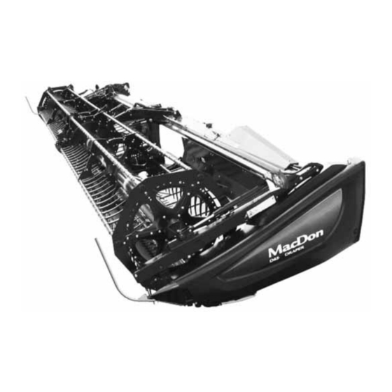
PRODUCT OVERVIEW 2.3 Component Identification Figure 2.2: D65 Windrower Header Components A - Reel Cam B - Pick-Up Reel Tines C - Drapers D - Center Reel Arm Prop Handle E - Hydraulic Connections F - Transport Light G - Reel Safety Prop... -
Page 51: Chapter 3: Operation
• It is your responsibility to read and understand this manual completely before operating the header. Contact your MacDon Dealer if an instruction is not clear to you. • Follow all safety messages in the manual and on safety decals on the machine. -
Page 52: Operational Safety
OPERATION 3.2 Operational Safety Follow all the safety and operational instructions given in this manual. CAUTION Adhere to the following safety precautions: • Follow all safety and operational instructions provided in your operator’s manuals. If you do not have a windrower manual, get one from your Dealer and read it thoroughly. -
Page 53: Reel Safety Props
OPERATION 3.2.2 Reel Safety Props The reel safety props are located on the reel arms. When engaged, the reel safety props prevent the reel from falling unexpectedly. IMPORTANT: To prevent damage to the reel support arms, do NOT transport the header with the reel safety props engaged. Engaging Reel Safety Props Engage the reel safety props whenever you intend to work on or around a raised reel. -
Page 54: Disengaging Reel Safety Props
OPERATION 5. Double-reel header, center arm: Use handle (A) to move the lock rod to inboard position (B) which engages pin (C) under the prop. 6. Lower the reel until the safety props contact the outer arm cylinder mounts and the center arm pin (the center arm only applies to double-reel headers). -
Page 55: Endshields
OPERATION 5. Double-reel headers, center reel arm: Use handle (B) to move lock rod (A) to the outboard position. Figure 3.6: Reel Safety Prop – Center Arm 3.2.3 Endshields A hinged, polyethylene endshield is fitted on each end of the header. Opening Endshield The header endshields cover components. -
Page 56: Closing Endshield
OPERATION IMPORTANT: Do NOT force the endshield once it has reached its end of travel or damage to the endshield structure may result. The endshield is designed to open sufficiently to allow access to the drive system and manual case. NOTE: To access the knife drive box, carefully disengage the front of endshield from the tab at the front of the endsheet and... -
Page 57: Removing Endshield
OPERATION 5. Replace tool (B) and lynch pin (A) on top pin (C). Figure 3.12: Left Endshield Pin Removing Endshield 1. Open the endshield. For instructions, refer to Opening Endshield, page 2. Remove acorn nut (A) securing the endshield to support (B). -
Page 58: Installing Endshield
OPERATION Installing Endshield 1. Position the endshield onto support (A), and align the hole in the endshield with stud (B) on the support. Figure 3.14: Left Endshield 2. Secure the endshield to the support with acorn nut (A). 3. Close the endshield. Refer to Closing Endshield, page NOTE: Polyethylene endshields may expand or contract when... -
Page 59: Adjusting Endshield
OPERATION Adjusting Endshield Polyethylene endshields expand or contract when subjected to large temperature changes. The position of the top pin and lower catch can be adjusted to compensate for dimensional changes. 1. Measure gap (X) between the front end of the endshield and the header frame and compare the measurement to the values provided in Table 3.1, page... -
Page 60: Daily Start-Up Check
OPERATION 3.2.4 Daily Start-Up Check Complete the following tasks each day before starting the machine. CAUTION • Clear the area of other persons, pets, etc. Keep children away from machinery. Walk around the machine to be sure no one is under, on, or close to it. •... -
Page 61: Break-In Period
OPERATION 3.3 Break-In Period Until you become familiar with the sound and feel of your new header, be extra attentive. CAUTION Before investigating an unusual sound or attempting to correct a problem, shut off engine and remove key. After attaching the header to the windrower for the first time, follow these steps: 1. -
Page 62: Shutting Down The Machine
OPERATION 3.4 Shutting down the Machine To prevent injuries and equipment damage, always perform the procedures for shutting down the machine. DANGER To prevent bodily injury or death from the unexpected start-up of the machine, always stop the engine and remove the key from the ignition before leaving the operator’s seat for any reason. -
Page 63: Cab Controls
OPERATION 3.5 Cab Controls The primary header functions are controlled inside the windrower cab. CAUTION Be sure all bystanders are clear of machine before starting engine or engaging any header drives. Refer to your windrower operator’s manual for identification of the following in-cab controls: •... -
Page 64: Header Setup
6 Options and Attachments, page 243 for descriptions of available items. 3.6.2 Header Settings The following table is a guideline for setting up the D65 Draper Header. Adjustments can be made to suit various crops and conditions not covered here. 214327... - Page 65 OPERATION 214327 Revision B...
- Page 66 OPERATION 214327 Revision B...
- Page 67 OPERATION 214327 Revision B...
- Page 68 OPERATION 214327 Revision B...
- Page 69 OPERATION 214327 Revision B...
-
Page 70: Reel Settings
The following chart illustrates the reel profile at each cam setting and the reel location relative to the ground at different positions on the reel arm. Refer to 3.6.2 Header Settings, page 44 for applicability of each finger pattern and reel position. Table 3.3 D65 Recommended Reel Settings Cam Setting Number Reel Position Reel Finger Pattern... - Page 71 OPERATION Table 3.3 D65 Recommended Reel Settings (continued) Cam Setting Number Reel Position Reel Finger Pattern (Finger Speed Gain) Number 3 (30%) 6 or 7 4 (35%) 2 or 3 NOTE: • Adjust the reel forward to position the fingers closer to the ground, while tilting the header back. Fingers/tines will dig into the ground at extreme reel-forward positions, so adjust skid shoes or header angle to compensate.
-
Page 72: Header Operating Variables
3.7.1 Cutting Height The D65 Draper Header is capable of cutting the crop to a desired stubble height or cutting as close as possible to the ground. Cutting height will vary depending on the type of crop, crop conditions, etc. - Page 73 OPERATION 3. Check that the float is working properly. Refer to your windrower operator’s manual for instructions. 4. Remove hairpin (A) from the latch on the right wheel assembly. 5. Disengage latch (B), lift the wheel out of the hook, and place the wheel on the ground as shown.
-
Page 74: Adjusting Stabilizer Wheels
OPERATION IMPORTANT: Continuous operation with excessive spring compression (that is, load indicator reading greater than 4 or a compressed length [A] less than 295 mm [11 5/8 in.]) can result in damage to the suspension system. 15. Adjust the header angle to the desired working angle with the machine’s header angle controls. -
Page 75: Cutting On The Ground
OPERATION 7. Lower the header to the desired cutting height and check load indicator (A). Figure 3.24: Load Indicator IMPORTANT: Continuous operation with excessive spring compression (that is, load indicator reading greater than 4 or a compressed length (A) less than 295 mm [11 5/8 in.]) can result in damage to the suspension system. -
Page 76: Adjusting Inner Skid Shoes
OPERATION Adjusting Inner Skid Shoes Adjust the inner skid shoes to affect stubble height when cutting on the ground. Ensure both inner and outer skid shoes should be set to the same height. DANGER To prevent bodily injury or death from the unexpected start-up or fall of a raised machine, always stop the engine, remove the key, and engage the safety props before going under the header for any reason. -
Page 77: Header Float
3.7.4 Header Float D65 Draper Headers are designed to ride on the skid shoes when cutting on the ground. The windrower float system reduces the ground pressure so that the header floats over obstacles and follows ground contours instead of being supported by the windrower lift cylinders. -
Page 78: Reel Speed
OPERATION 3.7.6 Reel Speed Reel speed is one of the factors that determines how crop is moved from the cutterbar onto the drapers. The reel performs best when it appears to be driven by the ground. It should move the cut crop evenly through the cutterbar and onto the drapers without bunching and with minimal disturbance. -
Page 79: Draper Speed
OPERATION Figure 3.29: Ground Speed vs Acres A - 4.6 m (15 ft.) B - 6.1 m (20 ft.) C - 7.6 m (25 ft.) D - 9.1 m (30 ft.) E - 10.7 m (35 ft.) F - 12.2 m (40 ft.) G - acres/hour H - miles/hour J - hectares/hour... -
Page 80: Checking Knife Speed
6. Compare pulley rpm measurement with the rpm values in the knife speed chart. For instructions, refer to 3.7.9 Knife Speed, page 7. Contact your MacDon Dealer if the pulley rpm measurement exceeds the specified rpm range for your header. Figure 3.31: Knife Drive Pulley 3.7.10 Reel Height... -
Page 81: Reel Fore-Aft Position
OPERATION The reel height is controlled using switches in the windrower cab. The following conditions might result if the reel is set too low: • Crop loss over the header backtube • Crop disturbance on the drapers caused by the reel fingers •... -
Page 82: Adjusting Reel Fore-Aft Position
OPERATION Adjusting Reel Fore-Aft Position The factory-set reel position suits normal conditions, but the fore-aft position can be adjusted as required using the controls inside the cab. 1. Select FORE-AFT mode on the selector switch in the cab. 2. Operate the hydraulics to move the reel to the desired position, using decal (A) as a reference. - Page 83 OPERATION 4. Push/pull the reel until bracket (B) lines up with the fore/ aft set of holes (C). 5. Reinstall the four bolts (A) securing the cylinder bracket (B) to the reel arm at the new position. Figure 3.35: Right Reel Arm Cylinder in Aft Position To reposition the left reel arm cylinder: 6.
-
Page 84: Repositioning Fore-Aft Cylinders On Double Reel
OPERATION Repositioning Fore-Aft Cylinders on Double Reel The reel can be moved approximately 227 mm (9 in.) farther aft by repositioning the fore-aft cylinders on the reel arms. DANGER To prevent injury or death from the unexpected start-up of the machine, always stop the engine and remove the key from the ignition before leaving the operator’s seat for any reason. - Page 85 OPERATION Reposition right arm cylinder as follows: NOTE: Reel components not shown in illustration for clarity. 6. Remove four bolts (A) securing cylinder bracket (B) to the reel arm. 7. Position reel until bracket (B) lines up with desired position holes (C): •...
-
Page 86: Repositioning Fore-Aft Cylinders With Multi-Crop Rapid Reel Conversion Option
OPERATION 13. Reposition bracket/light assembly (C) on the reel arm as shown, and secure with four bolts (D). Tighten bolts. 14. Push the reel back and attach cylinder (B) to bracket/light assembly (C) with pin (A). Secure pin with cotter pin. 15. - Page 87 OPERATION 5. Reinstall clevis pin (B) at the new position in bracket (C), and secure end of cylinder (D) with ring (A). Figure 3.45: Left Reel Arm in Aft Position To reposition the right reel arm cylinder: 6. Remove ring (A), clevis pin (B), and washers (C) from bracket (D).
-
Page 88: Reel Tine Pitch
OPERATION To reposition the right reel arm cylinder: 9. Remove ring (A), clevis pin (B), and washers (C) from bracket (D). Retain the ring, clevis pin, and washers. 10. Push the reel back until the end of cylinder (E) lines up with reel position 2 hole on bracket (D). - Page 89 OPERATION Cam Position 1, Reel Position 6 or 7 delivers the most even crop flow onto the drapers without fluffing up or disturbing the material. • This setting will release crop close to the cutterbar and works best if the cutterbar is on the ground. •...
-
Page 90: Adjusting Reel Cam
OPERATION Cam Position 4, Reel Position 2 or 3 is used with the reel fully forward to leave the maximum amount of stubble in lodged crops. • This position allows the reel to reach forward and lift the crop across the knife and onto the drapers. •... -
Page 91: Crop Dividers
OPERATION 4. Turn latch pin (A) counterclockwise using a 3/4 in. wrench to release the cam disc. 5. Use the wrench on bolt (B) to rotate the cam disc and align latch pin (A) with the desired cam disc hole position (C) (1 to 4). -
Page 92: Removing Crop Dividers Without Latch Option From Header
OPERATION 6. Lift safety lever (A). 7. Hold onto crop divider (B), push lever (C) to open the latch, and lower the crop divider. Figure 3.56: Crop Divider 8. Lift the crop divider off the endsheet and store as follows: Insert the pin on the crop divider into the hole in the endsheet at location (A) as shown. -
Page 93: Installing Crop Dividers With Latch Option Onto Header
OPERATION 6. Remove bolt (A), lock washer, and flat washer. 7. Lower crop divider (B) and then lift the crop divider to remove it from the endsheet. 8. Close or install the endshields. For instructions, refer to 3.2.3 Endshields, page Figure 3.58: Crop Divider Installing Crop Dividers with Latch Option onto Header To correctly install crop dividers with the latch option, follow the recommended installation procedure provided here. -
Page 94: Installing Crop Dividers Without Latch Option Onto Header
OPERATION 7. Position the crop divider as shown by inserting lugs (A) into the holes in the endsheet. 8. Lift the forward end of the crop divider until pin (B) at the top of the crop divider engages and closes latch (C). 9. - Page 95 OPERATION 4. Engage the header safety props. For instructions, refer to your windrower operator’s manual. 5. Open or remove the endshields. For instructions, refer to 3.2.3 Endshields, page 6. Remove the crop divider from the storage location by lifting the crop divider to disengage lugs (A) at the lower end and then lowering it slightly to disengage pin (B) from the endsheet.
-
Page 96: Crop Divider Rods
OPERATION 3.7.14 Crop Divider Rods Crop divider rods can be used in conjunction with crop dividers. The removable crop divider rods are most useful when crop is down. In standing crops using only crop dividers is recommended. Table 3.6 Crop Divider Rods Recommended Use With Divider Rods Without Divider Rods Alfalfa... -
Page 97: Rice Divider Rods
OPERATION Rice Divider Rods Rice divider rods attach to the left and right crop dividers. Optional rice divider rods provide improved performance in tall and tangled rice crops. For instructions, refer to 6.4.4 Rice Divider Rods, page 251. The installation and removal procedures are the same as for standard crop divider rods. -
Page 98: Delivery Opening
OPERATION 3.8 Delivery Opening The width and location of the delivery opening can be changed. This affects the width and configuration of the windrow. The decision to widen or narrow the center delivery opening, or to double windrow, should be based on the following factors: •... -
Page 99: Adjusting Delivery Opening On Header With Hydraulic Deck Shift
OPERATION 3.8.2 Adjusting Delivery Opening on Header with Hydraulic Deck Shift The delivery opening can be changed by moving the inboard deck shift stops. 1. Remove bolts (A). 2. Slide stop (B) outboard to decrease the maximum opening size, or inboard to increase the maximum opening. CAUTION Adjust the outboard stops to prevent the decks from contacting each other. - Page 100 OPERATION 2. Loosen jam nuts (B) and (C). 3. Turn nut (A) to adjust chain tension. Figure 3.71: Chain Adjustment Bolt – Left Shown, Right Similar Figure 3.72: HDS Chain – Left Shown, Right Similar 4. Measure to ensure chain midpoint (A) is 25–50 mm (1–2 in.) lower than the chain ends (B). 214327 Revision B...
- Page 101 OPERATION 5. Tighten jam nut (C). 6. Lock nut (B) against nut (A). NOTE: If there is less than 5 mm (3/16 in.) of thread visible beside jam nut (C), then remove nut (C). Figure 3.73: Chain Adjustment Bolt – Left Shown, Right Similar 214327 Revision B...
-
Page 102: Double Windrowing
OPERATION 3.9 Double Windrowing Double windrowing is laying two swaths side-by-side. Larger capacity combines or forage harvesters can then pick up twice as much material in a single pass, saving time and fuel. Double windrowing can be performed using two methods: deck shifting or using the Double Windrow Attachment (DWA). Deck shifting is used for crops that don’t require conditioning, such as grains, canola, and beans. - Page 103 OPERATION To deliver crop from the right end, move the decks to the left end of the header as follows: 2. Loosen bolt (A) on the right deck. 3. Slide the deck to close off the center opening. Tighten bolt (A). Figure 3.75: Right Deck Shown 4.
-
Page 104: Using Double Windrow Attachment
OPERATION To lay a double windrow, do the following: 5. Position decks at the left end of header to deliver crop from right end (A). 6. Complete one round or one length of the field. 7. Complete the second round or length in the opposite direction to lay a double windrow. - Page 105 OPERATION Figure 3.78: Double Windrowing To lay a double windrow, do the following: 1. Complete one round or one length of the field. 2. Complete the second round or length in the opposite direction to lay a double windrow. 3. Repeat above steps to lay additional double windrow. 214327 Revision B...
-
Page 106: Windrow Types
OPERATION 3.10 Windrow Types Review the qualities that make up a good windrow to better understand how the crop delivery method affects your windrow. There are three basic criteria by which the quality of a windrow is measured: • Weight Distribution: Heads and stalks distributed evenly across full width of windrow •... - Page 107 OPERATION Table 3.7 Windrow Descriptions (continued) Windrow Type Windrow Descriptions Description: The stalks are lined along outside edges of windrow and heads are crossed in Dovetail center. This windrow can be formed by center delivery only. Weight Distribution: Poor Curing: Fair Weatherability: Poor Machine Setting Guidelines: •...
- Page 108 OPERATION Table 3.7 Windrow Descriptions (continued) Windrow Type Windrow Descriptions Description: The stalks are lined along one edge and heads are along opposite edge, 45° to 45° Diagonal windrow perpendicular. This windrow can be formed by end delivery or by center delivery, if the crop is leaning to one side.
-
Page 109: Haying Tips
OPERATION 3.11 Haying Tips These tips may be useful when using the header in hay crops 3.11.1 Curing Curing crops quickly helps maintain the highest quality because for each day that hay lies on the ground, 5% of the protein is lost. -
Page 110: Windrow Characteristics
OPERATION 3.11.4 Windrow Characteristics Adjust speed and header variables to achieve the ideal windrow characteristics. Table 3.8 Windrow Characteristics Configuration Advantage Movement of air through the windrow is more important to the curing High and fluffy process than is direct sunlight. Permits an even flow of material into the baler, chopper, etc. -
Page 111: Leveling Header
OPERATION 3.12 Leveling Header The windrower linkages are factory-set to provide the proper level for the header and should not normally require adjustment. NOTE: The float springs are NOT used to level the header. 1. If the header is not level, check the pressure of the windrower’s tires to ensure they are properly inflated. For instructions, refer to the windrower operator’s manual. -
Page 112: Unplugging Cutterbar
OPERATION 3.13 Unplugging Cutterbar Follow safety procedures when clearing a plugged cutterbar, and refer to troubleshooting recommendations of plugging persists. DANGER To prevent bodily injury or death from the unexpected start-up or fall of a raised machine, always stop the engine, remove the key, and engage the safety props before going under the machine for any reason. -
Page 113: Upper Cross Auger (Option)
IMPORTANT: The UCA drive motor must be equipped with a case drain kit when used on single draper drive headers. See your MacDon Dealer for details. NOTE: Newer UCA kits do not include or use beater bars. -
Page 114: Installing Beater Bars
OPERATION Figure 3.81: Beater Bars 3.14.2 Installing Beater Bars Beater bars can improve the delivery of material through the header opening. DANGER To prevent bodily injury or death from the unexpected start-up of the machine, always stop the engine and remove the key from the ignition before making adjustments to the machine. - Page 115 OPERATION Figure 3.83: Beater Bars 214327 Revision B...
-
Page 116: Transporting Header
• Travel speed should be such that complete control and machine stability are maintained at all times. 3.15.2 Towing Header Headers with the optional Slow Speed Transport can be towed behind a properly configured MacDon windrower, a properly configured combine, or an agricultural tractor. -
Page 117: Attaching Header To Towing Vehicle
OPERATION Attaching Header to Towing Vehicle Review this list of cautions before attaching a header behind a MacDon windrower, a properly configured combine, or an agricultural tractor. CAUTION Adhere to the following slow speed transport instructions to prevent loss of control leading to bodily injury and/or machine damage: •... -
Page 118: Converting From Transport To Field Position
OPERATION 3.15.3 Converting from Transport to Field Position The header needs to be converted back to field position if it was towed to a new location. Removing Tow-Bar The transport tow-bar can easily be disassembled and stored on the header. 1. -
Page 119: Storing The Tow-Bar
OPERATION Storing the Tow-Bar The tow-bar consists of two sections: inner half (A) and outer half (B). Figure 3.87: Tow-Bar Assembly 1. On the left side of the header’s backtube, place the inner end of the outer half of the tow-bar into cradle (A). NOTE: The exact appearance of the tow-bar storage cradle varies according to the model of header. -
Page 120: Moving Front (Left) Wheels Into Field Position
OPERATION 4. On the right side of the header’s backtube, place the inner end of the inner half of the tow-bar into cradle (A). NOTE: The exact appearance of the tow-bar storage cradle varies according to the model of header. 5. - Page 121 OPERATION 4. Swivel front wheel assembly (A) so the wheels are aligned with the lower frame. 5. Remove pin (B) and pull the wheel assembly toward the rear of the header. Store the pin in hole (C) at the top of the leg.
-
Page 122: Moving Rear (Right) Wheels Into Field Position
OPERATION 9. Lift the wheel assembly to the desired height and slide linkage (A) into the appropriate slot in the vertical support. 10. Push handle (B) down to lock it. Figure 3.92: Front Wheels – Left Moving Rear (Right) Wheels into Field Position The rear wheels are located farthest from the towing vehicle. - Page 123 OPERATION 6. Pull pin (A) on brace (B) on the left wheel in front of the cutterbar. Disengage the brace from the cutterbar, and lower the brace against axle (C). 7. Remove pin (D), lower support (E) onto the axle, and reinsert the pin into the support.
-
Page 124: Converting From Field To Transport Position
OPERATION 13. Complete the conversion by ensuring left (A) and right (B) wheels are in the positions shown. Figure 3.97: Field Position 3.15.4 Converting from Field to Transport Position The header needs to be converted to the transport when being towed to a new location. Moving Front (Left) Wheels into Transport Position The front wheels are located closest to the towing vehicle. - Page 125 OPERATION 5. Remove the hairpin and clevis pin (A). 6. Pull latch handle (B) to release suspension linkage (C), and pull the suspension linkage away from spindle (D). 7. Lower the wheels slowly. Figure 3.99: Left Front Wheels 8. Lower handle (B) to lock. Figure 3.100: Locking Linkage 214327 Revision B...
-
Page 126: Moving Rear (Right) Wheels Into Transport Position
OPERATION 9. Remove pin (A) from storage at the top of leg (B). 10. Move and swivel the wheels clockwise until connector (C) is turned towards the front end of the header. 11. Insert pin (A) and turn to lock. 12. - Page 127 OPERATION 6. Remove pin (A) and install at location (B) to secure the linkage. Turn the pin to lock. 7. Pull pin (D), swivel wheel (C) counterclockwise 90°, and release the pin to lock. Figure 3.103: Wheel Position 8. Ensure the left wheel is in the transport position as shown. Figure 3.104: Left Wheel in Transport Position 9.
- Page 128 OPERATION 10. Lock wheel (A) with pin (B). Move right axle (C) to the front of the header. Figure 3.106: Right Rear Wheel 11. Remove pin (A), raise support (B) to the position shown, and reinsert pin. IMPORTANT: Ensure pin (A) engages the tube on the axle. 12.
-
Page 129: Attaching Tow-Bar
OPERATION Attaching Tow-Bar The tow-bar consists of two sections, which make storage and handling easier. 1. Unhook rubber strap (D) from cradle (A) on the right side of the header. 2. Remove clevis pin (C) and detach the tube end from support (B). - Page 130 OPERATION 8. Connect outer half (B) of the tow-bar to inner half (A). Figure 3.110: Tow-Bar Assembly 9. Lift outer half (B) and insert it into inner half (A). Figure 3.111: Tow-Bar Assembly 10. Secure the two halves together with L-pin (A) and then turn to lock.
- Page 131 OPERATION 12. Position tow-bar (A) onto the axle, and push against latch (B) until the tow-bar pins drop into hooks (C). 13. Check that latch (B) has engaged the tow-bar. 14. Install clevis pin (D) and secure with hairpin. Figure 3.113: Attaching Tow-Bar 15.
-
Page 132: Storing The Header
OPERATION 3.16 Storing the Header Ensure the header is ready for the next harvest by taking steps to prevent corrosion, reduce unnecessary wear, and replace worn components. CAUTION Never use gasoline, naphtha, or any volatile material for cleaning purposes. These materials may be toxic and/or flammable. -
Page 133: Chapter 4: Header Attachment/Detachment
Chapter 4: Header Attachment/Detachment This chapter includes instructions for attaching a header to, and detaching a header from a windrower. 4.1 Attaching Header to Windrower Refer to your windrower operator’s manual for instructions for mechanically attaching the header to the windrower. Refer to the following procedures for electrical and hydraulic connections. - Page 134 HEADER ATTACHMENT/DETACHMENT 5. Push the hose connectors onto the mating receptacle until the collar on the receptacle snaps into locked position. 6. Remove the cover from electrical receptacle (A). 7. Push the electrical connector onto the receptacle and turn the collar on the connector to lock it in. 8.
- Page 135 HEADER ATTACHMENT/DETACHMENT 11. Open the cover on header receptacle (A). 12. Push in lock button (B) and pull handle (C) to the half-open position. Figure 4.6: Reel Hydraulics Receptacle 13. Remove the hose bundle with multicoupler (C) from the windrower, place the multicoupler onto the header receptacle, and push handle (B) to engage the connector pins.
-
Page 136: Detaching Header From Windrower
HEADER ATTACHMENT/DETACHMENT 4.2 Detaching Header from Windrower To detach the header from an M Series Windrower, follow the procedure provided here. 1. Lower the header fully. 2. Lower the reel fully. 3. Shut down the engine, and remove the key from the ignition. Disconnecting reel hydraulics: 4. - Page 137 HEADER ATTACHMENT/DETACHMENT Disconnecting header drive hydraulics: 7. Disengage and rotate lever (A) counterclockwise to the fully up position. 8. Disconnect the electrical connector from the header. Figure 4.10: Header Drive Hydraulics 9. To disconnect the hoses from the header, line up slot (A) in collar with pin (B) on the connector.
-
Page 139: Chapter 5: Maintenance And Servicing
Chapter 5: Maintenance and Servicing This chapter contains the information necessary to perform routine maintenance and occasional servicing tasks on your machine. The word “maintenance” refers to scheduled tasks that help your machine operate safely and effectively; “service” refers to tasks that must be performed when a part needs to be repaired or replaced. For advanced service procedures, contact your Dealer. -
Page 140: Maintenance Specifications
MAINTENANCE AND SERVICING 5.2 Maintenance Specifications 5.2.1 Installing a Roller Chain When working on chain driven systems, you may need to install a new roller chain. This topic explains how to install a chain with a clip and pin connector link. DANGER To prevent bodily injury or death from the unexpected start-up of the machine, always stop the engine and remove the key from the ignition before leaving the operator’s seat for any reason. -
Page 141: Installing A Sealed Bearing
MAINTENANCE AND SERVICING 5.2.2 Installing a Sealed Bearing This installation procedure applies to all typical sealed bearings. 1. Clean the shaft and apply a rust preventive coating. 2. Install flangette (A), bearing (B), second flangette (C), and lock collar (D). NOTE: The locking cam is on only one side of the bearing. -
Page 142: Maintenance Requirements
MAINTENANCE AND SERVICING 5.3 Maintenance Requirements Regular maintenance is the best insurance against early wear and untimely breakdowns. Periodic maintenance requirements are organized according to service intervals. When servicing the machine, refer to the appropriate section in this chapter and use only the fluids and lubricants specified in Recommended Fluids and Lubricants on the inside back cover. -
Page 143: Break-In Inspection
MAINTENANCE AND SERVICING ü Draper seal ü Reel drive chain tension Reel tine/cutterbar ü clearance ü Knife drive belt tension ü Wheel bolt torque Knife drive box ü lubricant level Knife drive box ü mounting bolts S Reel drive chain Maintenance ▲... -
Page 144: Maintaining The Header - End-Of-Season
MAINTENANCE AND SERVICING CAUTION • Review this manual to refresh your memory on the safety and operating recommendations. • Review all the safety decals and other decals on the header and note the hazard areas. • Be sure all the shields and guards are properly installed and secured. Never alter or remove safety equipment. •... -
Page 145: Checking Hydraulic Hoses And Lines
MAINTENANCE AND SERVICING 5.3.5 Checking Hydraulic Hoses and Lines Check hydraulic hoses and lines daily for signs of leaks. WARNING • Avoid high-pressure fluids. Escaping fluid can penetrate the skin causing serious injury. • Keep your hands and body away from pinholes and nozzles which can eject fluids under high pressure. -
Page 146: Service Intervals
MAINTENANCE AND SERVICING Service Intervals Refer to the illustrations on the following pages to identify the various locations that require lubrication and servicing. Illustrations are organized by the frequency of service. IMPORTANT: Unless otherwise specified, use high temperature extreme pressure (EP2) performance with 1% maximum molybdenum disulphide (NLGI grade 2) lithium base. - Page 147 MAINTENANCE AND SERVICING Figure 5.7: Every 50 Hours – Upper Cross Auger, New Assembly A- Right End Bearing B - Two-Piece Auger Only: Upper Cross Auger U-joints [Two places, accessible by opening cover (D)] C - Two-Piece Auger Only: Upper Cross Auger Sliding Hubs [Two places, accessible by opening cover (D)] E - Two-Piece Auger Only: Upper Cross Auger Center Bearings (Two Places) 214327 Revision B...
- Page 148 MAINTENANCE AND SERVICING Figure 5.8: Every 50 Hours – Upper Cross Auger, Old Assembly A - Upper Cross Auger U-joint 48 B - Upper Cross Auger Bearing (2 Places) C - Right End Bearing 48. The U-joint has a cross and bearing kit with an extended lubrication interval. Stop greasing when greasing becomes difficult or if the U-joint stops taking grease.
- Page 149 MAINTENANCE AND SERVICING Figure 5.9: Every 100 Hours C - Reel Drive Chain (1 Place) (Double Reel Shown – Single Reel Similar) A - Knife Drive Box (Check Oil Level Between Lower Hole and End of Dipstick [B]) D - Hydraulic Couplers (Use WD40 ®...
- Page 150 MAINTENANCE AND SERVICING Figure 5.10: Every 250 Hours (Continued) B - Double Reel U-Joint (1 Place) 49 A - Front Wheel Pivot (1 Place) C - Frame/Wheel Pivot (1 Place) - Both Sides 49. The U-joint has a cross and bearing kit with an extended lubrication interval. Stop greasing when greasing becomes difficult or if the U-joint stops taking grease.
- Page 151 MAINTENANCE AND SERVICING Figure 5.11: Every 500 Hours A - Reel Right Bearing (1 Place) B - Reel Center Bearing (1 Place) C - Wheel Bearings (4 Places) D - Reel Left Bearing (1 Place) 214327 Revision B...
-
Page 152: Lubricating The Header
MAINTENANCE AND SERVICING Lubricating the Header Greasing points are marked on machine by decals showing a grease gun and grease interval in hours of operation. Master grease point location decals are provided on header. DANGER To prevent bodily injury or death from the unexpected start-up of the machine, always stop the engine and remove the key from the ignition before leaving the operator’s seat for any reason. -
Page 153: Lubricating Reel Drive Chain - Single Reel
MAINTENANCE AND SERVICING Figure 5.14: Double-Knife Header Master Grease Point Decal Lubricating Reel Drive Chain – Single Reel The reel drive chain should be lubricated every 100 hours. DANGER To prevent bodily injury or death from the unexpected start-up of the machine, always stop the engine and remove the key from the ignition before leaving the operator’s seat for any reason. -
Page 154: Lubricating Reel Drive Chain - Double Reel
MAINTENANCE AND SERVICING 3. Apply a liberal amount of grease to chain (A). Figure 5.16: Drive Chain 4. Position drive cover (B) onto the reel drive and secure it with four bolts (A). Figure 5.17: Drive Cover – Single Reel Lubricating Reel Drive Chain –... - Page 155 MAINTENANCE AND SERVICING 3. Remove three bolts (A) and remove lower cover (B) if necessary. Figure 5.19: Drive Cover – Double Reel 4. Apply a liberal amount of grease to chain (A). Figure 5.20: Drive Chain 5. Position lower drive cover (B) onto the reel drive (if previously removed) and secure with three bolts (A).
- Page 156 MAINTENANCE AND SERVICING 6. Position upper drive cover (B) onto the reel drive and lower cover (C), and secure with six bolts (A). Figure 5.22: Drive Cover – Double Reel 214327 Revision B...
-
Page 157: Electrical System
MAINTENANCE AND SERVICING 5.4 Electrical System The electrical wires and connectors that connect the header lights should be secured to avoid damage. Use electrical tape and wire clips as required to prevent wires from dragging or rubbing. Keep lights clean and replace defective bulbs. -
Page 158: Cutterbar
MAINTENANCE AND SERVICING 5.5 Cutterbar The cutterbar is located on the front of the header. It supports the knife and guards which are used to cut the crop. WARNING Keep hands clear of the area between guards and knife at all times. -
Page 159: Removing Knife
MAINTENANCE AND SERVICING 7. Reposition bars (C) and/or (D) on knife (A) and install lock nuts (B). NOTE: If replacing screws, ensure they are fully inserted. Do NOT use nuts to draw screws into the knife bar. 8. Torque the nuts to 9.5 Nm (7 lbf∙ft). Figure 5.27: Knife Bar 5.5.2 Removing Knife The cutterbar knife is designed to easily be replaced if worn or damaged. -
Page 160: Removing Knifehead Bearing
MAINTENANCE AND SERVICING 12. Wrap a chain around the knifehead and pull out the knife. 5.5.3 Removing Knifehead Bearing The knifehead bearing, seals, and greasing interval protect the knifehead from the forces of the knife drive output arm. The seals and bearing require inspection and, when worn—replacement to prevent damage. DANGER To prevent bodily injury or death from the unexpected start-up or fall of a raised machine, always stop the engine and remove the key before leaving the operator’s seat, and always engage the safety props before going under the... -
Page 161: Installing Knifehead Bearing
MAINTENANCE AND SERVICING 5.5.4 Installing Knifehead Bearing The knifehead bearing, seals, and greasing interval protect the knifehead from the forces of the knife drive output arm. The seals and bearing require inspection and, when worn—replacement to prevent damage. 1. Place O-ring (E) and plug (D) into the knifehead. IMPORTANT: Install the bearing with the stamped end (the end with the identification markings) facing up. -
Page 162: Spare Knife
To prevent injury or death from the unexpected start-up of the machine, always stop the engine and remove the key from the ignition before leaving the operator’s seat for any reason. NOTE: Use guard straightening tool (MD #140135) available from your MacDon Dealer. 214327 Revision B... -
Page 163: Replacing Pointed Guards
NOTE: If the crop is difficult to cut, install stub guards with top guards and adjuster plates. A kit is available from your MacDon Dealer. For information, refer to 6.2.3 Stub Guard Conversion Kit, page 247. Figure 5.35: Downward Adjustment Replacing Pointed Guards To replaced pointed guards, perform the recommended replacement procedure provided here. - Page 164 MAINTENANCE AND SERVICING 3. Remove two nuts (B) and bolts attaching guard (A) and hold-down (C) (if applicable) to the cutterbar. 4. Remove guard (A), hold-down (C) (if applicable), and plastic wearplate (if installed). Figure 5.36: Pointed Guards IMPORTANT: The first four outboard guards (B) on the drive sides of the header do NOT have ledger plates.
-
Page 165: Replacing Stub Guards
MAINTENANCE AND SERVICING 8. Remove two nuts (B) and bolts attaching guard (A) and hold-down (C) to the cutterbar. 9. Remove guard (A), plastic wearplate (if installed), hold- down (C), and adjuster bar (D). Figure 5.39: Center Guards 10. Position the plastic wearplate (if applicable), replacement center guard (A), adjuster bar, and hold-down (B) onto the cutterbar. - Page 166 MAINTENANCE AND SERVICING 2. Stroke the knife manually until the knife sections are spaced midway between the guards. 3. Remove two nuts (A) and bolts attaching guard (B) and hold-down (C) to the cutterbar. 4. Remove guard (B), plastic wearplate (if installed), hold- down (C), and adjuster bar (D).
- Page 167 MAINTENANCE AND SERVICING 5. Position the plastic wearplate (if applicable), replacement guard (B), adjuster bar (D), hold-down (C), and install bolts and nuts (A). Do NOT tighten. 6. Check and adjust the clearance between the hold-downs and the knife. For instructions, refer to Checking and Adjusting Knife Hold-Downs, page 148.
-
Page 168: Checking And Adjusting Knife Hold-Downs
MAINTENANCE AND SERVICING 8. Remove two nuts (A) and bolts attaching guard (B), hold- down (C), and adjuster bar (D) to the cutterbar. 9. Remove guard (B), plastic wearplate (if installed), hold- down (C), and adjuster bar (D). 10. Position the plastic wearplate (if applicable), replacement guard (B), adjuster bar (D), and hold-down (C) onto the cutterbar. -
Page 169: Adjusting Pointed Guard Hold-Downs
MAINTENANCE AND SERVICING 3. Manually stroke the knife to align section (A) under hold-down (B). 4. At standard guard locations, push knife section (A) down against guard (C) and measure the clearance between hold- down (B) and knife section (A) with a feeler gauge. The clearance should be 0.1–0.6 mm (0.004–0.024 in.). -
Page 170: Adjusting Hold-Down Clips At Double-Knife Center Pointed Guard
MAINTENANCE AND SERVICING 1. Shut down the windrower, and remove the key from the ignition. 2. Decrease the clearance by turning bolt (B) clockwise to lower the front of hold-down (A). 3. Increase the clearance by turning bolt (B) counterclockwise to raise the front of the hold-down. -
Page 171: Checking Stub Guard Hold-Downs
MAINTENANCE AND SERVICING Checking Stub Guard Hold-Downs This procedure is to measure clearance between hold-downs and knife sections on single- and double-knife headers with stub guards. DANGER To prevent bodily injury or death from the unexpected startup of the machine, always stop the engine and remove the key before adjusting the machine. -
Page 172: Adjusting Stub Guard Hold-Downs
MAINTENANCE AND SERVICING 5. Double-knife center stub guard: Manually stroke knife to locate sections under hold-down (B). Measure clearance between knife sections (A) and (C) with a feeler gauge. The clearance should be as follows: • At hold-down tip (D): 0.1–0.4 mm (0.004–0.016 in.) •... -
Page 173: Knifehead Shield
Remove the shields when cutting with the cutterbar on the ground in muddy conditions. Mud may pack into the cavity behind the shield which could result in knife drive box failure. The shields and mounting hardware are available from your MacDon Dealer. 214327... -
Page 174: Installing Knifehead Shield
MAINTENANCE AND SERVICING Installing Knifehead Shield The knifehead shield is supplied in flattened form, but it can be bent to suit installation on pointed or stub guard cutterbars. Knifehead shields differ slightly depending on header size and guard configuration, so ensure you are using the proper knifehead shield for your header. -
Page 175: Knife Drive
MAINTENANCE AND SERVICING 5.6 Knife Drive The knife drive system transforms pumped hydraulic pressure into a mechanical motion that stokes a series of serrated knife blades at the front of the header back and forth to cut a variety of crops. 5.6.1 Knife Drive Box Knife drive boxes convert rotational motion into the reciprocating motion of the knife, and are belt driven by a hydraulic motor. - Page 176 MAINTENANCE AND SERVICING NOTE: The procedure is the same for both ends of a timed double-knife header. Images shown are for the left end—the right end is opposite. 1. Shut down the engine, and remove the key from the ignition. 2.
- Page 177 MAINTENANCE AND SERVICING 11. Remove belt (A) from drive pulley (B). 12. Slip belt (A) over and behind knife drive box pulley (C). Use the notch in the pulley to assist with the belt removal. 13. Stroke the knife manually to its outer limit. Figure 5.60: Knife Drive 14.
-
Page 178: Removing Knife Drive Box Pulley
MAINTENANCE AND SERVICING 20. Remove bolt (A) that clamps knife drive arm (B) to the knife drive box output shaft. 21. Remove knife drive arm (B) from the knife drive box output shaft. 22. Remove four knife drive box mounting bolts (C) and (D). NOTE: Bolt (E) is factory set;... -
Page 179: Installing Knife Drive Box Pulley
MAINTENANCE AND SERVICING Installing Knife Drive Box Pulley The knife drive box pulley is driven by the knife drive motor and the knife drive belt. To install the knife drive box pulley, follow the recommended installation procedure provided here. 1. Ensure the splines and bores in the pulley and drive arm are free of paint, oil, and solvents. - Page 180 MAINTENANCE AND SERVICING 4. Apply two bands (A) of medium-strength threadlocker ® (Loctite 243 or equivalent) to the output shaft as shown. Apply one band at the end of the output shaft and the second band at the approximate midpoint location. 5.
- Page 181 15. Move the output arm to the midstroke position, and ensure the knife bar doesn’t contact the front of the first guard. If the knife drive box requires adjustment, contact your MacDon Dealer. 16. Install and tension the knife drive belts. Refer to the following topics depending on your header: •...
-
Page 182: Changing Oil In Knife Drive Box
MAINTENANCE AND SERVICING Changing Oil in Knife Drive Box Change the knife drive box lubricant after the first 50 hours of operation and every 1000 hours (or 3 years) thereafter. DANGER To prevent bodily injury or death from the unexpected start-up or fall of a raised machine, always stop the engine and remove the key from the ignition before making adjustments to the machine. -
Page 183: Knife Drive Belts
MAINTENANCE AND SERVICING 5.6.2 Knife Drive Belts The knife drive box is driven by a V-belt that is powered by a hydraulic motor on the header endsheets. Untimed Knife Drive Belts The knife drive box is driven by a V-belt that is powered by a hydraulic motor on the header endsheets. Removing Untimed Knife Drive Belts The untimed knife drive belt removal procedure is the same for both sides of a double-knife header. - Page 184 MAINTENANCE AND SERVICING 6. Remove belt (A) from drive pulley (B). 7. Slip belt (A) over and behind knife drive box pulley (C). Use the notch in the pulley to assist with the belt removal. Figure 5.75: Knife Drive Installing Untimed Knife Drive Belts The procedure for installing untimed knife drive belts is the same for both sides of the header.
- Page 185 MAINTENANCE AND SERVICING 3. Tension the knife drive belt. For instructions, refer to Tensioning Untimed Knife Drive Belts, page 165. 4. Install access cover (A) and secure it with a bolt. 5. Close the endshield. For instructions, refer to Closing Endshield, page Figure 5.77: Access Cover Tensioning Untimed Knife Drive Belts...
-
Page 186: Timed Double-Knife Drive Belts
MAINTENANCE AND SERVICING 5. Ensure the clearance between belt (A) and belt guide (B) is 1 mm (1/32 in.). 6. Loosen three bolts (C), and adjust the position of guide (B) as required. 7. Tighten three bolts (C). 8. Close the endshield. For instructions, refer to Closing Endshield, page NOTE:... - Page 187 MAINTENANCE AND SERVICING 1. Shut down the windrower, and remove the key from the ignition. 2. Install V-belts (C) onto the pulleys. NOTE: Ensure the drive motor is fully forward, do NOT pry the belts over the pulley. 3. Turn adjuster bolt (B) clockwise to tighten the V-belts. A properly tensioned V-belt should deflect 4 mm (5/32 in.) when 52–77 N (12–17 lbf) is applied at the midspan.
- Page 188 MAINTENANCE AND SERVICING NOTE: The following two steps apply only to the left drive. 5. Loosen two bolts (A) on the endsheet. 6. Turn adjuster bolt (B) counterclockwise to loosen it and remove two V-belts (C). Figure 5.83: Knife Drive V-Belts 7.
- Page 189 MAINTENANCE AND SERVICING 1. Shut down the engine, and remove the key from the ignition. 2. + Route knife drive belt (A) around pulley (B) and knife drive box pulley (C). NOTE: Ensure the drive motor is fully forward, do NOT pry the belt over the pulley.
- Page 190 MAINTENANCE AND SERVICING 9. Tension the knife drive belt. For instructions, refer to Tensioning Timed Knife Drive Belts, page 170. 10. Install access cover (A) and secure it with a bolt. 11. Close the endshield. For instructions, refer to Closing Endshield, page Figure 5.88: Access Cover Tensioning Timed Knife Drive Belts...
- Page 191 MAINTENANCE AND SERVICING 4. Position pry bar (A) under idler bracket (C), and push the bracket upward until a force of 27 N (6 lbf) deflects the belt 13 mm (1/2 in.) at the midpoint of the upper span. NOTE: Protect the paint by placing a piece of wood (B) under pry bar (A).
- Page 192 MAINTENANCE AND SERVICING Adjusting Double-Knife Timing Timed double-knife drive headers (10.7 m [35 ft.] and smaller) require the knives to be properly timed to move in opposite directions. DANGER To prevent bodily injury or death from the unexpected start-up or fall of a raised machine, always stop the engine and remove the key before leaving the operator’s seat, and always engage the safety props before going under the machine for any reason.
- Page 193 MAINTENANCE AND SERVICING 6. Install right knife drive belt (A). NOTE: Ensure the knife drive box driver and driven pulleys do NOT rotate during belt installation. Figure 5.95: Right Knife Drive 7. Rotate idler pulley bracket (A) downward, and slide the idler pulley up by hand to remove most of the belt slack.
- Page 194 MAINTENANCE AND SERVICING 9. When the belt has the proper belt tension, tighten nuts (C) to 73–80 Nm (54–59 lbf·ft). 10. Ensure the timing belts are properly seated in the grooves on both driver and driven pulleys. 11. Rotate the drive slowly by hand and observe where the knives overlap at the center of the header to check for the correct knife timing.
- Page 195 MAINTENANCE AND SERVICING 1. Open the endshields. For instructions, refer to Opening Endshield, page CAUTION Exercise extreme care when operating the header with the endshields open. 2. Operate the header and observe how the belt is tracking on both the drive pulley and the knife drive box pulley on both sides of the header.
- Page 196 MAINTENANCE AND SERVICING The cogged timing belt should be centered on the knife drive box pulley and at least 2 mm (0.08 in.) from either edge when the header is running. The belt should also avoid constant contact with the flanges on the drive pulley, but occasional contact is acceptable.
- Page 197 MAINTENANCE AND SERVICING Figure 5.103: Knife Drive – Right Side Adjusting Drive Belt Tracking – Knife Drive Box Pulley The following procedure is applicable to the left knife drive and the right knife drive on timed drive headers. The cogged timing belt should be centered on the knife drive box pulley and at least 2 mm (0.08 in.) from either edge when the header is running.
- Page 198 MAINTENANCE AND SERVICING 3. Remove nut (A) securing the idler to the bracket, and remove lock washer (D), the idler pulley, and flat washer (C). 4. Install idler pulley (B), ensuring it lines up with the knife drive box pulley, using flat washer(s) (C) as required. 5.
-
Page 199: Drapers
MAINTENANCE AND SERVICING 5.7 Drapers Two side drapers convey cut crop to the center opening. Replace the side drapers if they are torn, cracked, or missing slats. 5.7.1 Removing Side Drapers Replace the drapers if they are torn, cracked, or missing slats. DANGER To prevent bodily injury or death from the unexpected start-up or fall of a raised machine, always stop the engine and remove the key before leaving the operator’s seat, and always engage the safety props before going under the... -
Page 200: Installing Side Drapers
MAINTENANCE AND SERVICING 5.7.2 Installing Side Drapers Side drapers are used to bring cut crop to the center of the header. To ensure they are installed correctly, follow the recommended installation procedure provided here. DANGER To prevent bodily injury or death from the unexpected start-up or fall of a raised machine, always stop the engine and remove the key before leaving the operator’s seat, and always engage the safety props before going under the machine for any reason. - Page 201 MAINTENANCE AND SERVICING 11. Loosen mounting bolts (B) on rear deck deflector (A) (this may help with draper installation). Figure 5.108: Draper Seal 12. Attach the ends of the draper with tube connectors (B), screws (A) (with the heads facing the center opening), and nuts.
-
Page 202: Adjusting Draper Tension
MAINTENANCE AND SERVICING 16. Adjust backsheet deflector (A) (if required) by loosening nut (D) and moving the deflector until there is a 1–7 mm (3/64–9/32) gap (C) between draper (B) and the deflector. 17. Operate the drapers with the engine at idle so the talc or talc/graphite lubricant makes contact and adheres to the draper seal surfaces. - Page 203 MAINTENANCE AND SERVICING 6. Ensure the draper guide (the rubber track on the underside of the draper) is properly engaged in groove (A) on the drive roller. Figure 5.113: Drive Roller 7. Ensure idler roller (A) is between draper guides (B). Figure 5.114: Idler Roller 214327 Revision B...
-
Page 204: Adjusting Side Draper Tracking
MAINTENANCE AND SERVICING IMPORTANT: Do NOT adjust nut (C). This nut is used for draper alignment only. 8. Turn adjuster bolt (A) counterclockwise to loosen the draper. White indicator bar (B) will move outboard in the direction of arrow (D) to indicate that the draper is loosening. - Page 205 MAINTENANCE AND SERVICING 1. Refer to Table 5.1, page 184 to determine which roller requires adjustment and which adjustments are necessary. NOTE: To change the distance (X), adjust the back end of the roller using the adjuster mechanism at the inboard end of the deck.
-
Page 206: Adjusting Deck Height
MAINTENANCE AND SERVICING 5.7.5 Adjusting Deck Height The draper seal is the gap between the draper and the cutterbar. It should be inspected before the draper is operated to prevent potential damage to the draper system. DANGER To prevent injury or death from the unexpected start-up of the machine, always stop the engine and remove the key from the ignition before leaving the operator’s seat for any reason. - Page 207 MAINTENANCE AND SERVICING 5. Measure the clearance between the draper and the cutterbar at deck supports (A). For instructions, refer to Step 4, page 186. 6. Reduce the tension on the draper. For instructions, refer to 5.7.3 Adjusting Draper Tension, page 182.
- Page 208 MAINTENANCE AND SERVICING 11. Locate a feeler gauge of the same thickness as the draper belt plus 1 mm (1/16 in.). 12. Slide the feeler gauge along deck (A) under the cutterbar in order to properly set the gap. 13. To create a seal, adjust deck (A) so that clearance (B) between cutterbar (C) and the deck is the same thickness as the draper belt plus 1 mm (1/16 in.).
-
Page 209: Side Draper Roller Maintenance
MAINTENANCE AND SERVICING 5.7.6 Side Draper Roller Maintenance The draper rollers have non-greaseable bearings; however, the external seal should be checked every 200 hours (more frequently in sandy conditions) to achieve maximum bearing life. Inspecting Draper Roller Bearing Check for damaged draper roller bearings using an infrared thermometer as follows: 1. -
Page 210: Replacing Draper Idler Roller Bearing
MAINTENANCE AND SERVICING 7. Loosen the draper by turning adjuster bolt (A) counterclockwise. Figure 5.126: Tensioner 8. Remove screws (A), tube connectors (B), and nuts from the draper joint to uncouple the draper. 9. Pull the draper off the idler roller. Figure 5.127: Draper Joint 10. - Page 211 MAINTENANCE AND SERVICING 2. Remove bearing assembly (A) and seal (B) from roller tube (C) as follows: Attach slide hammer (D) to threaded shaft (E) in the bearing assembly. b. Tap out bearing assembly (A) and seal (B). 3. Clean the inside of roller tube (C), check the tube for signs of wear or damage, and replace it if necessary.
-
Page 212: Installing Draper Idler Roller
MAINTENANCE AND SERVICING Installing Draper Idler Roller The roller needs to be installed after it has been repaired or replaced 1. Position the stub shaft into the idler roller in forward arm (B) on the deck. 2. Push on the roller to slightly deflect the forward arm so the stub shaft at the rear of the roller can be slipped into rear arm (C). - Page 213 MAINTENANCE AND SERVICING 6. Loosen the draper by turning adjuster bolt (A) counterclockwise. Figure 5.132: Tensioner 7. Remove connectors (B), screws (A), and nuts from the draper joint to uncouple the draper. 8. Pull the draper off the drive roller. Figure 5.133: Draper Joint 9.
-
Page 214: Replacing Draper Drive Roller Bearing
MAINTENANCE AND SERVICING 11. Remove bolt (A) securing the opposite end of drive roller (B) to the support arm. 12. Remove drive roller (B). Figure 5.135: Drive Roller Replacing Draper Drive Roller Bearing You will need a slide hammer to remove and replace the bearing on a drive roller. 1. -
Page 215: Installing Draper Deck Drive Roller
MAINTENANCE AND SERVICING 4. Install new bearing assembly (A) by pressing the outer race of the bearing into the tube until it is 14–15 mm (0.55–0.2 in.) (B) from the outside edge of the tube. 5. Add approximately 8 cc or two pumps of grease in front of bearing assembly (A). -
Page 216: Replacing Draper Deflectors
MAINTENANCE AND SERVICING 7. Wrap the draper over the drive roller and attach the ends of the draper together using tube connectors (B), screws (A), and nuts. NOTE: The heads of the screws must face the center opening. Figure 5.140: Draper Joint 8. -
Page 217: Installing Wide Draper Deflectors
MAINTENANCE AND SERVICING 7. Open the endshield. For instructions, refer to Opening Endshield, page 8. Loosen nuts (A) on the cutterbar until retainer (B) is loose. Figure 5.142: Deflector Retainer 9. Remove fasteners securing the deflector to the endsheet. Nuts (A) are accessible from the side of the endshield, and nuts (B) on the uppermost fasteners are accessible from behind deflector (C). - Page 218 MAINTENANCE AND SERVICING WARNING To prevent bodily injury from the fall of a raised reel, always engage the reel safety props before going under the raised reel for any reason. 1. Raise the reel fully. 2. Lower the header fully. 3.
-
Page 219: Removing Narrow Draper Deflectors
MAINTENANCE AND SERVICING 17. Adjust the position of support (A) so that the tip contacts deflector (B). Tighten bolts (C). 18. Repeat the above steps for the opposite end. 19. Close the endshield. For instructions, refer to Closing Endshield, page 20. -
Page 220: Installing Narrow Draper Deflectors
MAINTENANCE AND SERVICING 7. Open the endshield. For instructions, refer to Opening Endshield, page 8. Remove two Torx ® head screws (A) and lock nuts. 9. Remove three carriage bolts (B) and lock nuts, and remove aft deflector (C). Figure 5.148: Aft Deflector 10. - Page 221 MAINTENANCE AND SERVICING 8. Position forward deflector (B) onto the endsheet and temporarily install forward and aft 3/8 in. x 5/8 in. self- tapping screws (A). 9. Check the fit of the forward end of deflector (B) on the cutterbar and ensure there is no gap between the deflector and cutterbar.
-
Page 222: Reel
MAINTENANCE AND SERVICING 5.8 Reel The reel features a uniquely shaped cam, which allows the fingers to get underneath lodged crop and pick it up before it is cut. CAUTION To avoid personal injury, before servicing machine or opening drive covers, refer to 5.1 Preparing Machine for Servicing, page 119. - Page 223 MAINTENANCE AND SERVICING 2. Set the fore-aft position to middle position 5 on fore-aft position indicator decal (A). 3. Lower the reel fully. 4. Shut down the engine, and remove the key from the ignition. Figure 5.153: Fore-Aft Position 5. Measure the clearance at the ends of each reel at locations (A).
-
Page 224: Adjusting Reel Clearance
MAINTENANCE AND SERVICING 6. Check finger clearance (X) when positioned between locations (A) and (B). Depending on the reel fore-aft position, the minimum clearance can result at the guard tine, hold-down, or cutterbar. For finger clearance measurements, refer to Table 5.2, page 202. -
Page 225: Reel Frown
MAINTENANCE AND SERVICING 3. Move the reel back to ensure the steel end fingers do not contact the deflector shields. 4. If contact is evident, adjust the reel upward to maintain the clearance at all reel fore/aft positions. Alternatively, trim the steel end fingers to obtain the proper clearance. -
Page 226: Centering Double Reel
MAINTENANCE AND SERVICING • Centering Double Reel, page 206 • Centering Single Reel, page 207 Centering Double Reel The reel needs to be centered on the header to avoid any contact with the endsheets. DANGER To prevent bodily injury or death from the unexpected start-up or fall of a raised machine, always stop the engine, remove the key, and engage the safety props before going under the header for any reason. -
Page 227: Centering Single Reel
MAINTENANCE AND SERVICING Centering Single Reel The reel needs to be centered on the header to avoid any contact with the endsheets. 1. Start the engine and set the cutterbar height at approximately 150 mm (6 in.) above the ground. 2. -
Page 228: Removing Steel Tines
MAINTENANCE AND SERVICING Removing Steel Tines Damaged steel fingers will need to be cut off of the reel tine tube. DANGER To prevent bodily injury or death from the unexpected start-up of the machine, always stop the engine and remove the key from the ignition before making adjustments to the machine. -
Page 229: Removing Plastic Fingers
MAINTENANCE AND SERVICING IMPORTANT: Ensure the tine tube is supported at all times to prevent damage to the tube and other components. 1. Remove the applicable tine. For instructions, refer to Removing Steel Tines, page 208. 2. Slide the new tines and reel arm (A) onto the end of the tube. -
Page 230: Installing Plastic Fingers
MAINTENANCE AND SERVICING 2. Push the top of the finger off the reel tine tube while slightly pulling on the tine under the tube. The finger can then be removed. Figure 5.168: Removing Plastic Fingers Installing Plastic Fingers Once the old plastic reel finger has been removed, a new one can be installed. DANGER To prevent bodily injury or death from the unexpected start-up or fall of a raised machine, always stop the engine, remove the key, and engage the safety props before going under the header for any reason. -
Page 231: Tine Tube Bushings
MAINTENANCE AND SERVICING IMPORTANT: Do NOT apply force to the finger prior to tightening the mounting screw. Applying force without tightening the mounting screw will break the finger or shear the locating pins. 3. Install screw (A) using a Torx ®... - Page 232 MAINTENANCE AND SERVICING 5. Remove the reel endshields and endshield support (C) from the tail end of the reel at the applicable tine tube location. NOTE: There are no endshields on the center disc. 6. Remove bolts (A) securing arm (B) to the disc. IMPORTANT: Note the hole locations in the arm and disc, and ensure bolts (A) are reinstalled at the original locations.
- Page 233 MAINTENANCE AND SERVICING 10. Remove the endshields and endshield support (A) at the applicable tine tube location on the cam end. NOTE: Removing the cam end bushings requires the tine tube be moved through the disc arms to expose the bushing. Figure 5.174: Cam End 11.
- Page 234 MAINTENANCE AND SERVICING 14. Remove bolt (A) from the cam linkage so the tine tube (B) is free to rotate. NOTE: Be sure to not lose the shim, and mark the shim location for reassembly. Figure 5.177: Cam End 15. Release bushing clamps (A) at the cam disc using a small screwdriver to separate the serrations.
- Page 235 MAINTENANCE AND SERVICING 18. Locate support (A) that requires a new bushing. 19. Remove four bolts (B) securing channels (C) to support (A). 20. If finger (D) is too close to the support to allow access to the bushing, remove screw (E) and remove finger (D). For instructions, refer to Removing Plastic Fingers, page 209.
-
Page 236: Installing Bushings On Five-, Six-, Or Nine-Bat Reels
MAINTENANCE AND SERVICING 23. Slide support (A) off bushing halves (B). NOTE: Two tine tubes have opposite-facing supports. Rotate the supports until the flanges clear the channels before moving them off bushing (B). Move the tine tube outward slightly if necessary. - Page 237 MAINTENANCE AND SERVICING NOTE: Use a pair of modified channel lock pliers (A) to install bushing clamps (C). Secure the pliers in a vise and grind a notch (B) into the end of each arm to fit the clamp as shown. Figure 5.185: Modified Pliers Installing cam end bushings: 1.
- Page 238 MAINTENANCE AND SERVICING 6. Tighten clamp (A) using modified channel lock pliers (B) until finger pressure will NOT move the clamp. IMPORTANT: Overtightening the clamp might break the clamp. Figure 5.188: Clamp on Bushing 7. Line up tine tube (B) with the cam arm and install bolt (A). Apply medium-strength threadlocker (Loctite ®...
- Page 239 MAINTENANCE AND SERVICING 10. Install endshield support (A) at the applicable tine tube location at the cam end. 11. Reinstall the reel endshields. For instructions, refer to 5.8.6 Reel Endshields, page 223. Figure 5.191: Cam End 214327 Revision B...
- Page 240 MAINTENANCE AND SERVICING Installing center disc and tail-end bushings: 12. Position bushing halves (B) on the tine tube with the flangeless end adjacent to the reel arm, and position the lug in each bushing half into the hole in tine tube (A). 13.
- Page 241 MAINTENANCE AND SERVICING 18. Install bolts (A) securing arm (B) to the center disc. 19. Install reel arm (B) and endshield support (C) to the tail end of the reel at the applicable tine tube location, and secure them with bolts (A). Figure 5.195: Tail End Installing tine tube support (if installed) bushings: 20.
- Page 242 MAINTENANCE AND SERVICING 22. For the opposite tine tube, rotate support (A) or slightly move the tine tube until it clears channels (C). Figure 5.198: Opposite Support 23. Install bushing clamp (A) onto the tine tube adjacent to the flangeless end of bushing (B). 24.
-
Page 243: Reel Endshields
MAINTENANCE AND SERVICING 26. Reattach channels (C) to support (A) with screws (B) and nuts. Torque the screws to 43 Nm (32 lbf∙ft). 27. Reinstall any fingers (D) that were previously removed using screws (E). For instructions, refer to Installing Plastic Fingers, page 210. - Page 244 MAINTENANCE AND SERVICING 1. Lower the header and reel, shut down the engine, and remove the key from the ignition. 2. Rotate the reel manually until reel endshield support (A) requiring replacement is accessible. 3. Remove three bolts (B). Figure 5.203: Reel Endshields 4.
-
Page 245: Replacing Reel Endshield Supports
MAINTENANCE AND SERVICING 6. Remove reel endshield (A) from support (B). 7. Install new reel endshield (C) onto support (B). 8. Reattach reel endshield (A) onto support (B), ensuring it is installed on top of reel endshield (C). 9. Reinstall bolts (D). 10. - Page 246 MAINTENANCE AND SERVICING 10. Check the clearance between the tine tube and the reel endshield support, and adjust it if necessary. 11. Torque the nuts to 27 Nm (20 lbf·ft). 214327 Revision B...
-
Page 247: Reel
MAINTENANCE AND SERVICING 5.9 Reel All 7.6 m (25 ft.) and smaller headers have single reels, 9.1–10.7 m (30–35 ft.) headers are available in single-reel and double-reel versions, and all headers larger than 10.7 m (35 ft.) are only available in double-reel configurations. Single reels are driven from the right arm and double reels are driven from the center arm. -
Page 248: Installing Reel Drive Cover
MAINTENANCE AND SERVICING Double-Reel Drive: 3. Stop the engine, and remove the key from the ignition. 4. Remove six bolts (A) securing upper cover (B) to the reel drive and lower cover (C). Figure 5.210: Drive Cover – Double Reel 5. -
Page 249: Adjusting Reel Drive Chain Tension
MAINTENANCE AND SERVICING Double-Reel Drive: 2. Position lower drive cover (B) onto the reel drive (if previously removed) and secure it with three bolts (A). Figure 5.213: Drive Cover – Double Reel 3. Position upper drive cover (B) onto the reel drive and lower cover (C), and secure it with six bolts (A). -
Page 250: Tightening Reel Drive Chain
MAINTENANCE AND SERVICING 3. Loosen six nuts (A). Slide motor (B) and motor mount (C) down toward the reel shaft. Figure 5.215: Single-Reel Drive Shown – Double-Reel Drive Similar Figure 5.216: Single-Reel Drive – Viewed from Underside of Reel Tightening Reel Drive Chain A correctly tensioned drive chain ensures optimum power transfer while minimizing component wear. - Page 251 MAINTENANCE AND SERVICING 2. Ensure six bolts (A) securing the motor mount to the chain case are loose. Figure 5.217: Single-Reel Drive Shown – Double Reel Similar 3. Slide motor (A) and motor mount (B) upward until chain (C) is tight. Figure 5.218: Single-Reel Drive Shown –...
-
Page 252: Replacing Reel Drive Sprocket
MAINTENANCE AND SERVICING Figure 5.220: Single-Reel Drive – Viewed from Underside of Reel 5.9.3 Replacing Reel Drive Sprocket The reel drive sprocket is attached to the reel drive motor. Removing Reel Drive Sprocket The reel drive sprocket is attached to the reel drive motor. DANGER To prevent bodily injury or death from the unexpected start-up or fall of a raised machine, always stop the engine, remove the key, and engage the safety props before going under the header for any reason. -
Page 253: Installing Reel Drive Sprocket
MAINTENANCE AND SERVICING 4. Remove cotter pin (A), slotted nut (B), and flat washer (C) from the motor shaft. 5. Remove drive sprocket (D). Ensure the key remains in the shaft. IMPORTANT: To avoid damaging the motor, use a puller if the drive sprocket does not come off by hand. -
Page 254: Replacing Double-Reel U-Joint
MAINTENANCE AND SERVICING 5.9.4 Replacing Double-Reel U-Joint The double-reel drive U-joint allows each reel to move independently from the other. Lubricate the U-joint according to specifications. For instructions, refer to 5.3.6 Lubrication, page 125. Replace the U-joint if it is severely worn or damaged. For instructions, refer to Removing Double-Reel U-Joint, page 234. - Page 255 MAINTENANCE AND SERVICING 1. Position U-joint flange (B) onto driven sprocket (C) as shown. Install six bolts (A) and hand-tighten them. Do NOT torque the bolts. Figure 5.227: U-Joint 2. Position the right reel tube against the reel drive and engage the stub shaft into the U-joint pilot hole.
-
Page 256: Replacing Reel Drive Motor
5.9.5 Replacing Reel Drive Motor The reel drive motor does not require regular maintenance or servicing. If problems occur with the motor, remove it and have it serviced at your MacDon Dealer. Removing Reel Drive Motor The reel drive motor does not require regular maintenance or servicing. If problems occur with the motor, remove it and have it serviced at your MacDon Dealer. -
Page 257: Replacing Drive Chain On Double Reel
MAINTENANCE AND SERVICING 2. Attach motor (A) (and spacer if previously removed) to motor mount (B) with four 1/2 in. x 1 3/4 in. countersunk bolts and nuts (C). 3. Torque nuts (C) to 73 Nm (54 lbf∙ft). 4. If installing a new motor, install the hydraulic fittings (not shown) and torque them to 110–120 Nm (81–89 lbf·ft). - Page 258 MAINTENANCE AND SERVICING 3. Support the inboard end of the right reel with a front end loader and nylon slings (A) (or equivalent lifting device). IMPORTANT: Support the reel as close to the end disc as possible to avoid damaging or denting the center tube. Figure 5.234: Supporting Reel 4.
-
Page 259: Replacing Drive Chain On Single Reel
MAINTENANCE AND SERVICING 8. Position right reel tube (A) against the reel drive and engage the stub shaft into the U-joint pilot hole. 9. Rotate the reel until the holes in end of the reel tube and U-joint flange line up. 10. -
Page 260: Transport System (Optional)
MAINTENANCE AND SERVICING 5.10 Transport System (Optional) The header can be equipped with a set of transport wheels so that the header can be towed by a windrower, combine, or tractor. Refer to 6.3.3 Stabilizer / Slow Speed Transport Wheels, page 249 for more information. -
Page 261: Checking Tire Pressure
MAINTENANCE AND SERVICING Figure 5.241: Axle Bolts 1. Check and tighten axle bolts DAILY until the torque is maintained as follows: • (A): 244 Nm (180 lbf·ft) • (B): 203 Nm (150 lbf·ft) • (C): 244 Nm (180 lbf·ft) 5.10.3 Checking Tire Pressure Proper tire pressure ensures tires perform properly and wear evenly. -
Page 263: Chapter 6: Options And Attachments
Chapter 6: Options and Attachments The following options and attachments are available for use with your header. See your MacDon Dealer for availability and ordering information. 6.1 Reel 6.1.1 Multi-Crop Rapid Reel Conversion Kit For use on double-reel headers only, the Multi-Crop Rapid Reel... -
Page 264: Reel Endshield Kit
They are standard equipment on all headers (except nine-bat reels). Hardware and installation instructions are included in the kit. See your MacDon Dealer for more information. Figure 6.3: Reel Endshields 6.1.5 Short Brace Kit For Center Reel Arm... -
Page 265: Tine Tube Reinforcing Kit
OPTIONS AND ATTACHMENTS 6.1.6 Tine Tube Reinforcing Kit Tine tube reinforcing kits are available for five- and six-bat reels. They are designed to support high reel loads when cutting extremely heavy crops. Installation instructions are included in the kit. • Five-Bat Reels – MD #B5825 •... -
Page 266: Cutterbar
OPTIONS AND ATTACHMENTS 6.2 Cutterbar 6.2.1 Cutterbar Wearplate Cutterbar wearplates are recommended for cutting on the ground when the soil is adhering to the steel. Installation instructions are included in the kit. Order one of the following bundles according to your header size: •... -
Page 267: Stub Guard Conversion Kit
OPTIONS AND ATTACHMENTS 6.2.3 Stub Guard Conversion Kit Stub guards, complete with top guides and adjuster shoes, are designed to cut tough crops. Installation and adjustment instructions are included in the kit. Order one of the following bundles according to your header size: •... -
Page 268: Header
OPTIONS AND ATTACHMENTS 6.3 Header 6.3.1 Divider Latch Kit Divider latch kits attach to the endsheets. They allow for quick removal and storage of endsheet divider cones and, if required, reduce the transport width of the header. Installation instructions are included in the kit. MD #B5607 Figure 6.9: Divider Latch 6.3.2 Stabilizer Wheels... -
Page 269: Stabilizer / Slow Speed Transport Wheels
OPTIONS AND ATTACHMENTS 6.3.3 Stabilizer / Slow Speed Transport Wheels Stabilizer/slow speed transport wheels help to stabilize the header in field conditions that would otherwise cause the header to bounce, resulting in uneven cutting heights. This system is similar to the Stabilizer Wheel option. For more information about that option, refer to 6.3.2 Stabilizer Wheels, page... -
Page 270: Crop Delivery
OPTIONS AND ATTACHMENTS 6.4 Crop Delivery 6.4.1 Draper Deflector (Narrow) Narrow metal draper deflectors attach to the inboard side of the endsheets to prevent material from falling through the gap between the endsheet and the draper while minimizing reel carryover in bushy crops. NOTE: Narrow draper deflectors are not recommended for double windrowing –... -
Page 271: Draper Clips
OPTIONS AND ATTACHMENTS 6.4.3 Draper Clips Draper clips offer additional wear protection for the draper cleats. They may prove useful in situations where conditions are dry or consistently hot. Figure 6.14: Draper Clips Installation instructions are included with the kit. •... -
Page 272: Double Draper Drive Kit
OPTIONS AND ATTACHMENTS 6.4.5 Double Draper Drive Kit The Double Draper Drive (DDD) kit provides power to four draper rollers instead of the usual two in order to minimize draper slipping when using the side delivery feature in heavy forage crops. Installation instructions are included with the kit. -
Page 273: Swath Forming Rods (Center Delivery)
OPTIONS AND ATTACHMENTS 6.4.8 Swath Forming Rods (Center Delivery) Swath forming rods form windrows so the heads are in the center and protected from shatter. Swath forming rods are mainly used for grass seed cutting applications. Installation and adjustment instructions are included with the kit. -
Page 274: Hc10 Hay Conditioner
OPTIONS AND ATTACHMENTS 6.4.10 HC10 Hay Conditioner When paired with a windrower and a draper header, the HC10 hay conditioner lays uniform, fluffy windrows. Conditioning or crimping the cut hay allows the release of moisture resulting in faster drying times and earlier processing. A parts list and installation and operating instructions are included with the kit. -
Page 275: Upper Cross Auger (Uca) Hydraulic Kit For Double Draper Drive (Ddd)
OPTIONS AND ATTACHMENTS Installation instructions are included with the kit. Order from the following bundles according to your header size: • 4.6 m (15 ft.) – MD #B6280 • 6.1 m (20 ft.) – MD #B6281 • 7.6 m (25 ft.) – MD #B6461 •... -
Page 277: Chapter 7: Troubleshooting
Replace with standard torque Sprocket, page 232 (6 mph) with high torque (10-tooth) (19-tooth) reel drive sprocket reel drive sprocket • See your MacDon Dealer Worn or broken knife components Replace knife components 5.5 Cutterbar, page 138 Symptom: Strips of Uncut Material Allow enough room for crop to be fed —... - Page 278 247 material bridging the knife guards • See your MacDon Dealer Symptom: Material Accumulating in Gap between Cutout in Endsheet and Knifehead Crop heads leaning away from Add knifehead shield(s), except in 5.5.8 Knifehead Shield, page 153...
-
Page 279: Cutting Action And Knife Components
• 6.2.3 Stub Guard Conversion Kit, Install stub guards Tangled / tough to cut crop page 247 • See your MacDon Dealer 3.7.11 Reel Fore-Aft Position, page 61 Reel too far back Move reel forward • Tensioning Untimed Knife Drive... - Page 280 Mud or dirt build up on cutterbar Raise cutterbar by lowering skid shoes 3.7.3 Cutting on the Ground, page 55 Mud or dirt build up on cutterbar See your MacDon Dealer Install cut-out sections Mud or dirt build up on cutterbar Flatten header angle...
-
Page 281: Reel Delivery
Reel speed too fast Reduce reel speed 3.7.6 Reel Speed, page 58 Crop conditions Install optional endshields See your MacDon Dealer 5.8.3 Centering Reel, page 205 Reel not centered in header Center reel in header Symptom: Reel Releases Crop too Quickly... - Page 282 TROUBLESHOOTING Problem Solution Refer to Symptom: Reel Motion is Uneven or Stalls in Heavy Crops Reel speed too fast Reduce reel speed 3.7.6 Reel Speed, page 58 Move to a more aggressive finger Reel fingers not aggressive enough 3.7.12 Reel Tine Pitch, page 68 pitch notch 3.7.10 Reel Height, page 60 Reel too low...
-
Page 283: Header And Drapers
247 Material not feeding evenly off knife Install stub guards • 5.5.7 Knife Guards, page 142 • See your MacDon Dealer Symptom: Hesitation in Flow of Bulky Crop Header angle too low Increase header angle Controlling Header Angle, page 57... - Page 284 TROUBLESHOOTING Problem Solution Refer to Symptom: Crop is Thrown Across Opening and under Opposite Side Draper Drapers running too fast in light crop Reduce draper speed 3.7.8 Draper Speed, page 59 Symptom: Material Accumulates inside or under Front Edge of Draper Deck height improperly adjusted Adjust deck height 5.7.5 Adjusting Deck Height, page 186...
-
Page 285: Cutting Edible Beans
3.7.3 Cutting on the Ground, page 55 Skid shoes too low Dirt packs on bottom of cutterbar and Install plastic wear strips on bottom of See your MacDon Dealer raises cutterbar off the ground cutterbar and skid shoes Dirt packing on bottom of cutterbar —... - Page 286 TROUBLESHOOTING Problem Solution Refer to Divider rod running down crop and 3.7.14 Crop Divider Rods, page 76 Remove divider rods shattering pods Vines and plants build up on endsheet 3.7.14 Crop Divider Rods, page 76 Install divider rods Plant Vines Pinched between Top of Draper and Cutterbar Cutterbar has filled up with trash with Raise header fully at each end of field, —...
- Page 287 TROUBLESHOOTING Problem Solution Refer to Raise header fully at each end of field Excessive gap between top of front of — or as required and shift decks back draper and cutterbar and forth to help clean out cutterbar Symptom: Reel Carries Over Odd Plants in Same Location Reel steel fingers bent and hook —...
-
Page 288: Windrow Formation
TROUBLESHOOTING 7.6 Windrow Formation Use the following tables to determine the cause of any windrow formation problems and the recommended solutions. Problem Solution Refer to Symptom: Heads on Ground and Scattered Draper speed too slow Increase draper speed 3.7.8 Draper Speed, page 59 Draper angle too flat Increase header angle Controlling Header Angle, page 57... -
Page 289: Chapter 8: Reference
Chapter 8: Reference This chapter provides quick access to frequently needed information or numbers (for example, units of measurement or torque values). 8.1 Conversion Chart Both SI units (including metric) and US customary units (sometimes referred to as standard units) of measurement are used in this manual. -
Page 290: Torque Specifications
REFERENCE 8.2 Torque Specifications The following tables provide torque values for various bolts, cap screws, and hydraulic fittings. Refer to these values only when no other torque value has been specified in a given procedure. • Tighten all bolts to the torque values specified in the charts below, unless you are directed otherwise in this manual. •... - Page 291 REFERENCE Table 8.3 SAE Grade 5 Bolt and Grade F Distorted Thread Nut Torque (Nm) Torque (lbf·ft) (*lbf·in) Nominal Size (A) Min. Max. Min. Max. 1/4-20 16.7 18.5 5/16-18 *149 *164 3/8-16 7/16-14 1/2-13 9/16-12 5/8-11 3/4-10 Figure 8.2: Bolt Grades 7/8-9 A - Nominal Size B - SAE-8...
-
Page 292: Metric Bolt Specifications
REFERENCE 8.2.2 Metric Bolt Specifications Specifications are provided for the appropriate final torque values to secure various sizes of metric bolts. NOTE: The torque values provided in the following metric bolt torque tables apply to hardware installed dry; that is, hardware with no grease, oil, or threadlocker on the threads or heads. -
Page 293: Metric Bolt Specifications - Cast Aluminum
REFERENCE Table 8.8 Metric Class 10.9 Bolts and Class 10 Free Spinning Nut Torque (Nm) Torque (lbf·ft) (*lbf·in) Nominal Size (A) Max. Max. Min. Min. 3-0.5 3.5-0.6 4-0.7 5-0.8 6-1.0 14.3 15.8 *140 *154 8-1.25 10-1.5 12-1.75 Figure 8.7: Bolt Grades 14-2.0 16-2.0 20-2.5... -
Page 294: Flare-Type Hydraulic Fittings
REFERENCE Table 8.10 Metric Bolt Bolting into Cast Aluminum Bolt Torque Nominal 10.9 Size (A) (Cast Aluminum) (Cast Aluminum) lbf·ft lbf·ft – – – – – – – – – – – Figure 8.9: Bolt Grades – – – – 8.2.4 Flare-Type Hydraulic Fittings The standard torque values are provided for flare-type hydraulic fittings. -
Page 295: O-Ring Boss Hydraulic Fittings - Adjustable
REFERENCE Table 8.11 Flare-Type Hydraulic Tube Fittings (continued) Torque Value Flats from Finger Tight (FFFT) Thread Size (in.) SAE Dash Size Swivel Nut or lbf·ft Tube Hose 1 1/16–12 113–124 83–91 1 1/2 1 1/4 1 3/16–12 136–149 100–110 1 1/2 1 1/4 1 5/16–12 160–176... - Page 296 REFERENCE 5. Install fitting (B) into the port until backup washer (D) and O-ring (A) contact part face (E). 6. Position the angle fittings by unscrewing no more than one turn. 7. Turn lock nut (C) down to washer (D) and tighten it to the torque value indicated in the table.
-
Page 297: O-Ring Boss Hydraulic Fittings - Non-Adjustable
REFERENCE 8.2.6 O-Ring Boss Hydraulic Fittings – Non-Adjustable The standard torque values for non-adjustable hydraulic fittings are provided. If a procedure specifies a different torque value for the same type and size of fitting found in this topic, use the value specified in the procedure instead. 1. - Page 298 REFERENCE 1. Ensure that the sealing surfaces and the fitting threads are free of burrs, nicks, scratches, and any foreign material. Figure 8.14: Hydraulic Fitting 2. Apply hydraulic system oil to O-ring (B). 3. Align the tube or hose assembly so that the flat face of sleeve (A) or (C) comes into full contact with O-ring (B).
-
Page 299: Tapered Pipe Thread Fittings
REFERENCE Table 8.14 O-Ring Face Seal (ORFS) Hydraulic Fittings (continued) Torque Value Thread Size (in.) Tube O.D. (in.) SAE Dash Size lbf·ft 1 11/16 1 1/4 205–226 151–167 1 1/2 1–2 315–347 232–256 2 1/2 510–561 376–414 8.2.8 Tapered Pipe Thread Fittings The standard torque values are provided for tapered pipe thread fittings. -
Page 300: Unloading And Assembly
Refer to the instructions for your specific header for unloading, assembly, and setup procedures that are included with your shipment. The instruction part numbers are shown in the following table: MacDon Instruction Shipping Destination Header Description Part Number D65 Draper Header for North America MD #214328 Self-Propelled Windrowers Export (anywhere other than North D65 Draper Header for... -
Page 301: Index
Index crop dividers............71 installing on header with latch option ..... 73 installing on header without latch option ....74 definition............23 removing from header with latch option ....71 ASTM removing from header without latch option..... 72 definition............23 cutterbars attaching to windrower ......... - Page 302 INDEX removing............196 float ..............57 wide draper deflector (option) ......250 draper extension kit ..........252 drapers adjusting glossary ..............23 tension ............182 greasing tracking............184 See also lubrication and servicing deflectors ............196 greasing procedure..........132 draper roller bearings ground speeds ............
- Page 303 INDEX hydraulic deck shift (option) ........254 removing............158 operating............82 mounting bolts ..........155 hydraulics removing box ........... 155 checking ............125 knife drives ............155 fittings knives ............. 139 flare-type ............. 274 knife guards O-ring boss (ORB) adjustable ......275 adjusting ............
- Page 304 INDEX electrical system ..........137 draper extension kit ........252 end of season service......... 124 HC10 hay conditioner ........254 fluids and lubricants .......... 289 swath forming rods (center delivery) ....253 installing a sealed bearing........121 upper cross auger .......... 254 maintenance specifications .........
- Page 305 INDEX installing ............159 replacing sprocket.......... 232 removing............158 speed ............58 sprocket installing ........... 233 optional ............58 removing ..........232 recommended fluids and lubricants ......289 reel endshields reel drives replacing endshield support......225 double-reel drive replacing reel endshield ........223 U-joint reel finger ............
- Page 306 INDEX locations............vii records.............. vii tension service intervals ........... 126 definition............23 servicing, See maintenance and servicing TFFT setting up the header..........280 definition............23 settings tines attachments............44 optional kits reel..............50 tine tube reel conversion kit ......243 short brace kit .............
- Page 307 INDEX transporting on windrower ........96 troubleshooting ........... 257 definition............23 crop loss at cutterbar......... 257 cutting action and knife components ....259 cutting edible beans .......... 265 header and drapers ........... 263 reel delivery ............. 261 windrow formation ........... 268 trucks definition............
-
Page 309: Recommended Fluids And Lubricants
Recommended Fluids and Lubricants Ensure your machine operates at top efficiency by using clean fluids and lubricants only. • Use clean containers to handle all fluids and lubricants. • Store fluids and lubricants in an area protected from dust, moisture, and other contaminants. Lubricant Specification Description... - Page 310 CUSTOMERS M M a a c c D D o o n n . . c c o o m m DEALERS P P o o r r t t a a l l . . M M a a c c D D o o n n . . c c o o m m Trademarks of products are the marks of their respective manufacturers and/or distributors.
Need help?
Do you have a question about the D65 and is the answer not in the manual?
Questions and answers