
Related Manuals for Yamaha AW2816


Summary of Contents for Yamaha AW2816
- Page 1 PROFESSIONAL AUDIO WORKSTATION PROFESSIONAL AUDIO WORKSTATION Owner’s Manual Owner’s Manual Keep This Manual For Future Reference. Keep This Manual For Future Reference.
- Page 2 300 ohm ribbon lead, change the lead-in to coaxial type cable. If these corrective measures do not produce satisfactory results, please contact the local retailer authorized to distribute this type of product. If you can not locate the appropriate retailer, please contact Yamaha Corporation of America, Electronic Service Division, 6600 Orangethorpe Ave, Buena Park, CA 90620 The above statements apply ONLY to those products distributed by Yamaha Corporation of America or its subsidiaries.
- Page 3 Raadpleeg uw leverancier over de verwijdering van de batterij op het moment dat u het apparaat ann het einde van de levensduur afdankt of de volgende Yamaha Service Afdeiing: Yamaha Music Nederland Service Afdeiing Kanaalweg 18-G, 3526 KL UTRECHT Tel.
- Page 4 Important Read the following before oper- ating the AW2816 Warnings • Do not place a container with liquid or small metal objects on top of this unit. Liquid or metal objects inside this unit are a fire and electrical shock hazard.
- Page 5 Responsibility for loss of data, etc. • Yamaha will accept no responsibility for any dam- ages (including consequential or incidental) incurred by the customer or any third party as a result of loss or impairment of the data stored on...
-
Page 6: Table Of Contents
Stereo output channel...31 Buses 1–8 ...31 AUX buses 1–6 ...31 Output patch ...32 Internal effects 1/2 ...32 Monitor output/headphone output...32 The track structure of the AW2816...33 Audio tracks...33 Virtual tracks...33 The stereo track ...33 About the display...34 Cursor ...34 Buttons...35 Knobs/faders/numerical boxes ...35... - Page 7 Using MTC to synchronize the AW2816 and an external device... 192 Using MIDI clock to synchronize the AW2816 and an external device ... 194 Using MMC to control the AW2816... 196 Synchronizing two AW2816 units ... 197 Remotely switching AW2816 scenes .. 200 Controlling AW2816 parameters from an external device ...
- Page 8 Table of contents SONG screen FILE screen CD screen QUICK REC screen SETUP screen UTILITY screen MIDI screen PATCH screen VIEW screen PAN/ROUTE screen EQ/ATT/GRP screen DYN/DLY screen AUX1–AUX4 screens AUX5/EFF1, AUX6/EFF2 screens REMOTE screen HOME screen TRACK screen EDIT screen AUTOMIX screen SCENE screen METER screen...
- Page 9 —Appendix— Preset EQ Program Parameters... 356 Preset Effects Programs... 360 Effects Parameters... 362 Dynamics Processors ... 377 Preset Dynamics Programs ...377 Preset Dynamics Program Parameters 382 Troubleshooting... 388 Display message list ... 392 Messages ...392 Popup messages ...394 Messages at power-on ...395 Specifications...
-
Page 10: Before You Begin
Before you begin This chapter explains preparations you need to make before using the AW2816, such as checking the included items and installing options. Checking the included items Please make sure that the package contains the fol- lowing items. If any items are missing, please contact your dealer. -
Page 11: Installing An Internal Hard Disk
Before you begin Installing an internal hard disk You must install a hard disk in the AW2816 before using it. If you attempt to use the AW2816 without installing a hard disk, the recorder section and mixer section will fail to operate correctly, and the AW2816 will be damaged as well. - Page 12 4, or identical screws. Using longer screws may damage the interior of the unit, or may cause elec- trical shock. • Do not turn on the power of the AW2816 until all options have been installed. • When you turn on the power of the AW2816 after...
-
Page 13: Installing A Cd-Rw Drive
CD- RW drive to set your CD-RW drive to function as a SLAVE unit. The AW2816 will not start up if the CD- RW is set to a mode other than SLAVE. -
Page 14: Installation Procedure
• Work surface • In order to install the CD-RW drive you will need to turn the AW2816 on its back. Make sure that you have a sufficiently broad work surface. • The AW2816 is shipped with four screws for attach- ing the 2.5 inch hard disk, and four screws for... - Page 15 Before you begin Align the fastening screw-holes on the bot- tom of the CD-RW drive with the screw- holes in the AW2816, and using a screw- driver and the included screws, fasten it in four locations. Re-attach the CD-RW drive cover and the bottom panel that you removed in step 4.
-
Page 16: Removing The Transport Protection Pad
2 mm or less in diameter, such as a straightened paper clip. Eject Hall Insert a pin-like object 2 mm or less in diameter. * This diagram shows a CD-RW drive manufac- tured by Yamaha Corporation. Operation section... -
Page 17: Attaching An External Scsi Device
SCSI ID of each device does not conflict with any other device. (For details on how to set the SCSI ID, refer to the manuals for your SCSI devices.) • The SCSI ID of the AW2816 itself is fixed at “6.” Operation section SCSI connector... -
Page 18: About Terminators
SCSI bus (in the case of the example in the previous page, this would be the AW2816 itself, and the SCSI device connected to the end of the daisy chain). -
Page 19: Installing I/O Card
I/O cards compatible with the Yamaha mini-YGDAI format can be installed in the OPTION I/O slot located on the rear panel of the AW2816 in order to add input/output ports. For example by installing an ADAT format compatible I/O card into an OPTION I/ O slot, you can transmit/receive eight channels of dig- ital audio to/from an ADAT format digital recorder. -
Page 20: Please Observe The Following Points
Please observe the following points This section explains how to turn the power of the AW2816 on and off, and how to set the internal clock. Turning the power on When turning on the power of a system that includes the AW2816, each device must be turned on in the following order. -
Page 21: Turning The Power Off
When a message of “Now safe to turn off” appears, turn off the [POWER] switch of the rear panel. • If you turn off the power of the AW2816 without using the above shutdown procedure, the data on the hard disk may be damaged. -
Page 22: Analog Input/Output Section
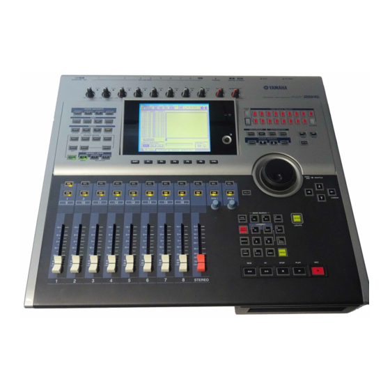
Chapter Parts and their functions This chapter explains the functions of each part of the AW2816’s top panel, rear panel, and front panel. The names of controllers (keys and knobs etc.) on the top panel are enclosed in square brackets [ ] in order to distinguish them from the software knobs and buttons that appear in the display. -
Page 23: Work Navigate Section
WORK NAVIGATE section [SONG] key This key accesses the SONG screen, where you can save or load songs, or shut down the AW2816. [FILE] key This key accesses the FILE screen, where you can backup and restore songs, and format or erase an internal/external drive. -
Page 24: Fader Mode Section
FADER MODE section This section selects the parameters that will be con- trolled by the top panel faders 1–8. The selected key will light. [HOME] key When this key is on, you can use faders 1–8 to control the input levels of the channels currently selected in the MIXING LAYER section. -
Page 25: Fader Section
Parts and their functions Fader section [SEL] keys (1–8/STEREO/RTN 1/RTN 2) These keys select the channel for operation. [ON] keys (1–8/STEREO/RTN 1/RTN 2) These keys turn each channel on/off. Faders (1–8/STEREO) According to the settings of the FADER MODE section and MIXING LAYER section, these moving faders adjust either the input level of each channel or the send level of each channel to AUX buses 1–... -
Page 26: Display Section
When the hard disk is being read or written, this indicator will light. Never turn off the power of the AW2816 when the access indicator is lit. Doing so will not only damage the data on the internal hard disk, but may also dam- age the hard disk itself. -
Page 27: Rec Track Select Section
Parts and their functions REC TRACK SELECT section [CUE] key This key allows the output of tracks 1–16 or the stereo track to be monitored directly from the MONITOR OUT jacks without passing through the monitor channel. Use the REC TRACK SELECT keys (3) to select a track. -
Page 28: Automation Section
AUTOMATION section [AUTOMIX] key This key accesses the AUTOMIX screen, where you can perform automix operations. By using automix, operations of mix parameters such as the faders and [ON] keys can be recorded in realtime. [SCENE] key This key accesses the SCENE screen, where you can perform scene memory operations. -
Page 29: Locate Section
Parts and their functions LOCATE section [NUM LOCATE] key This key is used to specify a location numerically. When this key is lit, you can use the numeric keys or the [DATA/JOG] dial to input a location, and press the [ENTER] key to execute the locate opera- tion. -
Page 30: Transport Section
Transport section REW [ ] (Rewind) key This key rewinds from the current location. Each time you press this key, you will switch between 8X speed and 16X speed rewinding. To stop rewinding, press the STOP [ ] key or PLAY [ key. -
Page 31: Rear Panel
Parts and their functions [PHANTOM +48V ON/OFF] switch This switch supplies +48 V phantom power to the INPUT (XLR) 1/2 jacks (2). Turn this switch ON when condenser mics that require an external power supply are connected to the INPUT 1/2 (XLR) jacks. - Page 32 Macintosh for use with MIDI application pro- grams. FOOT SW jack An optional foot switch (Yamaha FC5) can be con- nected to this jack. You can use the foot switch to perform transport operations such as playback/ stop, and to control manual punch-in/out.
-
Page 33: Front Panel
Parts and their functions CD-RW drive cover This covers the installation bay for the optional CD-RW drive. Tip! For details on installing a CD-RW drive, refer to page 4. Front panel Operation section... -
Page 34: Mixer Section
Chapter Welcome to the world of the AW2816 This chapter explains the features and signal flow of the AW2816, and covers basic operation. The AW2816 is an audio workstation that combines a digital mixer, hard disk recorder, and multi-effect unit. -
Page 35: Cd-Rw Drive (Option)
WAV files can be loaded from CD-ROM or MO disk, and audio from tracks recorded on the AW2816 can be converted and written as a WAV file. This allows audio files to be exchanged with waveform editing software running on your com- puter. -
Page 36: Input Patch
Signal flow within the AW2816 The following diagram shows the general signal flow within the AW2816. As you can see from this dia- gram, the AW2816 is divided into input patch, output patch, mixer, recorder, and CD-RW drive (option) sec- tions. - Page 37 Welcome to the world of the AW2816 MIC/LINE INPUT PHANTOM +48V PEAK INPUT LINE MIC PEAK INPUT LINE MIC Hi-z INPUT 8 ONLY OPTION I/O SLOT SLOT IN EFFECT1 EFFECT2 DIGITAL STEREO IN COAXIAL METRONOME Input channels 1–8 These are monaural input channels used mainly for inputting mics or line-level instruments.
- Page 38 Return channels 1/2 These are stereo input channels used mainly for input- ting the return signal from internal effects 1/2. How- ever, the input signal assignment can be changed in the input patch section, allowing these to be used as additional input channels.
-
Page 39: Digital Cascade Connection
AW2816. Cascade connection settings are made in the SETUP screen D.in Setup page. Oscillator The AW2816 contains an oscillator that allows you to select either sine wave (100 Hz, 1 kHz, 10 kHz) or white noise. The oscillator signal can be sent to buses 1–8, AUX buses 1–6, or the stereo bus. -
Page 40: Stereo Output Channel
METER METER LEVEL METER METER LEVEL Tip! With the AW2816’s default settings, the output of AUX buses 5/6 is sent to the output patch section, and also assigned to the input of internal effects 1/2. STEREO METER LEVEL METER CD PLAY mode BUS 1(...8) -
Page 41: Output Patch
AW2816. 1 When the AW2816 is in the default state The signal of the stereo output channel will be out- put directly to the MONITOR OUT jacks/PHONES jack. -
Page 42: Audio Tracks
These are the physical tracks on which recording and playback is performed, and are also referred to simply as “tracks.” When the AW2816 is in the default state, the outputs of buses 1–8 are patched to the inputs of tracks 1–8/9–16, and the outputs of tracks 1–16 are patched to monitor channels 1–16, allowing up to six-... -
Page 43: About The Display
2 to AUX bus 5). The knob will be high- lighted at the – dB, 0 dB, and +6 dB positions. Tip! When the AW2816 is in the default state, the name (scene name) of the selected scene and the current tempo/time signature information will be briefly dis- played in the 6 and 7 areas when you press the [ ] keys of the SCENE MEMORY section. -
Page 44: Buttons
Buttons Buttons in the display are used to switch a parameter on/off, or to select one of multiple choices. Currently- on buttons are highlighted as white text on a black background, and currently-off buttons are displayed as black text on a white background. Knobs/faders/numerical boxes Knobs/faders/numerical boxes in the display are used to edit the value of the corresponding parameter. -
Page 45: Accessing Screens And
Accessing screens and pages When you want to operate a mix parameter or edit an internal setting of the AW2816, you must first recall the desired screen in the display. if a screen is divided into multiple pages, select the desired page after recalling the screen. -
Page 46: Using The Additional Function Buttons
Using the additional function buttons When a symbol is shown in the lower left of the display, you can press and hold the [SHIFT] key to access new buttons in the bottom of the display, and use various additional functions. In a screen that displays a symbol in the lower left, press and hold the [SHIFT] key. -
Page 47: Selecting A Channel
Selecting a channel In order to operate the mix parameters of a channel on the AW2816, you must first select the channel that you want to operate. Here’s how to select a channel. Use the keys of the MIXING LAYER section to select the mixing layer that you want to operate. - Page 48 The following table shows how the parameters con- trolled by faders 1–8 will change depending on the fader mode. Fader mode MIXING LAYER : INPUT [1–8] HOME Input levels of input channels 1–8 Send levels from input channels 1–8 AUX 1 to AUX bus 1 Send levels from input channels 1–8 AUX 2...
-
Page 49: Connections And Setup
Let’s record on the AW2816 As a way to explain the basic operations of multi-track recording and mixdown on the AW2816, this chapter describes how you can suc- cessively record instruments such as rhythm machine (drums), bass, guitar, and keyboard to create a song. You will also learn more advanced techniques that you will find convenient. -
Page 50: Creating A New Song
AW2816 the AW2816 itself your monitor sys- tem. When you turn on the power of the AW2816, the song that was used most recently will be loaded automatically. If SCSI devices are connected to the AW2816, the... - Page 51 Use the Fs and Recbit buttons to select the sampling frequency and number of quanti- zation bits for the newly created song. • It is not possible to change the sampling frequency or quantization after creating the song. • The quantization you select here will affect the number of tracks that can be played back simulta- neously while multiple tracks are being recorded simultaneously.
-
Page 52: Word Clock Settings
If you are digitally connecting an external device such as a digital MTR or sampler to the AW2816, select the word clock master as described below. • Be aware that if your system contains an unsynchro- nized device, dropouts and click noise will occur. - Page 53 Fs (sampling frequency) field in the upper left of the display. Digital MTR • If you are using the internal clock of the AW2816 as the clock source, the sampling frequency selected when you created the current song will be the sam- pling frequency of the entire system.
-
Page 54: Setting The Input Level
INPUT jacks 1/2 to be recorded on tracks 1/2. The procedure described below assumes that the AW2816 is in the default state. If internal settings have already been modified, recall scene number 00 from scene memory to return the internal settings of the AW2816 to the default state ( P.129). -
Page 55: Pairing Two Channels
1/ When the AW2816 is in the default state, the input signals of the INPUT 1–8 jacks are assigned to input channels 1–8 respectively, as shown in the following diagram. -
Page 56: Patching Input Signals To Recorder Inputs
Track 2 Stereo bus Tip! When the AW2816 is in the default state, input chan- nels 1–8 are assigned to the stereo bus, and can be monitored from the MONITOR OUT jacks/PHONES jack. However in this example we want to send the... - Page 57 When the AW2816 is in the default state, the outputs of buses 1–8 (BUS 1–BUS 8) are assigned to recorder inputs 1–8/9–16 as shown in the dia- gram below. Recorder input patch Mixer section Recorder section Buses 1–8 Tracks 1–8 Tracks 9–16...
-
Page 58: Adjusting The Monitor Level
Let’s record on the AW2816 Adjusting the monitor level Now we will send the signal of the rhythm machine (drum recording mics) via monitor channels 1/2 to the stereo bus, and monitor it from the MONITOR OUT jacks or PHONES jack. - Page 59 Recording Now we will record the signal of the rhythm machine (drum recording mics) on tracks 1/2. Press the [METER] key [F2] key to display the METER screen Meter 2 page. The METER screen Meter 2 page will display the input/output levels of tracks 1–16 and the output level of the stereo output channel, as well as a counter in large numerals.
-
Page 60: Patching The Input Signal To The Recorder Input
When the AW2816 is in the default state, the input signal of INPUT jack 8 is patched to input channel 8. If the input channel 8 level meter reaches the “OVER”... - Page 61 Press the INPUT [1-8] key [SEL] key 8. On the AW2816, you specify the channel that you want to operate by first selecting the mixing layer in the MIXING LAYER section, and then using a [SEL] key to select the desired channel.
-
Page 62: Applying The Equalizer To The Input Signal
3 to a volume that is comfortable for monitoring. Applying the equalizer to the input signal The AW2816 provides 4-band full-parametric EQ on all channels. Here’s how to use the input channel EQ to process the signal before it is recorded on the track. [SEL] key... - Page 63 find convenient to use. Applying the dynamics proces- sor to the input signal All channels of the AW2816 (except for return chan- nels 1/2) provide a dynamics processor that can be used as a compressor, limiter, or gate. This section...
- Page 64 Let’s record on the AW2816 Move the cursor to the RECALL button at the left of the library list, and press the [ENTER] key. A CONFIRMATION popup window will appear, asking you whether you really want to recall the data.
-
Page 65: Recording
Recording Now we will record the bass sound on track 3. In the Locate section, press the [ The counter in the display will rewind to the zero location (00:00:00.000). To begin recording, hold down the REC [ ] key and press the PLAY [ The REC [ ] key and PLAY [ ] key will light,... -
Page 66: Mixing To The Stereo Track (Mixdown)
Let’s record on the AW2816 Mixing to the stereo track (Mixdown) This section explains how to mix the signals recorded on tracks 1–16 down to a stereo signal, use the inter- nal effect processors to add effects, and record the result on the stereo track. -
Page 67: Using The Internal Effects
field and turn the [DATA/ JOG] dial to change the setting. • With the default settings of an AW2816 song, the output of AUX buses 5/6 is patched to the input of internal effects 1/2, and the output of internal effects 1/2 is patched to the input of return channels 1/2. -
Page 68: Recording On The Stereo Track
1. [F3] key. Recording on the stereo track The AW2816 has a stereo track that is independent of audio tracks 1–16, and is used as a master track to create a final mix. When using a CD-RW drive to cre- ate an audio CD, this stereo track is what will be writ- ten to the CD. - Page 69 If you play back the song now, you can monitor the stereo track via monitor channels 1/2 However if you play back with the AW2816 in this state, the playback sound will be affected by the settings (pan, EQ, dynamics processor) of...
-
Page 70: Saving Your Song
• If you turn off the power of the AW2816 without saving the current song, any changes you made to the settings within the current song will be lost. • To turn off the power of the AW2816, you must use the Shutdown procedure ( P.12). Press the [SONG] key The SONG screen Song List page will appear. - Page 71 Locate the song to a point ahead of where you will punch-in. Tip! • If you want to use a foot switch (Yamaha FC-5) to perform manual punch-in/out, connect the foot switch to the rear panel FOOT SW jack before you continue.
- Page 72 Let’s record on the AW2816 Automatically re-recording only a specific area (Auto Punch-in/out) It is also possible to automatically punch-in/out when you come to a pre-specified point. This is called “auto punch-in/out.” This section explains the procedure for auto punch-in/out.
- Page 73 To rehearse auto punch-in/out, press the PLAY [ ] key. The PLAY [ ] key will light, and playback will begin from the pre-roll point. When you reach the auto punch-in point, the REC [ ] key will begin blinking, and the sig- nal being monitored for the track you selected in step 3 will switch from the track playback sound to the input signal (the...
-
Page 74: Switching Virtual Tracks
Let’s record on the AW2816 Switching virtual tracks On the AW2816, you can select and record or play- back one of eight virtual tracks 1–8 for each of the audio tracks 1–16. For example when you are recording a solo part on... - Page 75 Operating multiple faders together (Fader Groups) “Fader grouping” is a function that lets you operate the faders of multiple channels as a group. Channels that are registered in the same fader group can be controlled together by operating just one of the faders. Press the [EQ] key [F3] key.
- Page 76 Let’s record on the AW2816 Operating multiple [ON] keys together (Mute Groups) “Mute grouping” is a function that lets you operate the [ON] of multiple channels as a group. Channels that are registered in the same mute group can be turned on/off together by operating just one of the [ON] keys.
-
Page 77: Using The Solo Function
Using the Solo function The AW2816 contains a very flexible Solo function. By pressing the [SOLO] key on the top panel and then pressing the [ON] key for a desired channel, you can monitor that channel by itself. Press the [SETUP] key [F5] key. - Page 78 Let’s record on the AW2816 To enable the Solo function, press the [SOLO] key. The [SOLO] key and [ON] keys 1–8 will blink. Use the keys of the MIXING LAYER section to select the desired mixing layer, and use the [ON] keys to select the channel that you want to solo.
- Page 79 ASSIGN area of this page displays the signals that are assigned to input channels 1–8 and return channels 1/2 With the default settings of an AW2816 song, the input signals shown in the following diagram are assigned to input channels 1–8 and return channels 1/...
- Page 80 Input/output patching Move the cursor to the channel whose patching you want to change, and use the [DATA/JOG] dial to select the desired sig- nal. The following signals can be assigned to each channel. • Input channels 1–8 Display AD 1–AD 8 INPUT jacks 1–8 SLT-1–SLT-8 INPUT 1–8 of an I/O card...
- Page 81 The RECORDER CHANNEL INPUT ASSIGN area of this page displays the signals that are assigned to recorder inputs 1–16. With the default settings of an AW2816 song, the bus 1–8 signals are assigned to recorder inputs 1–16 as shown in the diagram below.
- Page 82 DIGITAL STEREO OUT jack STEREO OUT jacks Output channels 1–8 of an I/O card (OPTION I/O slot) With the default settings of the AW2816, the follow- ing signals are assigned to the various output jacks and output channels. Output Patch...
- Page 83 • DIGITAL STEREO OUT jack • STEREO OUT jacks Display Signal type ST L/R Stereo output channel (L/R) BUS 1/2–7/8 Buses 1/2–7/8 Direct output of input chan- DIR 1/2–DIR 7/8 nels 1/2–7/8 AUX 1/2–AUX 5/6 AUX buses 1/2–5/6 RDR 1/2–RDR15/ Direct output of tracks 1/2–15/ •...
-
Page 84: Using The Patch Library
Input/output patching Using the patch library Up to 20 different patching settings you make in the PATCH screen Patch IN page and Patch OUT page can be stored in an area of internal memory called the “patch library.” The contents of the patch library are saved on the internal hard disk as part of the song. -
Page 85: Recalling Patching Settings From The Library
Recalling patching settings from the library Here’s how to recall (load) patching settings that were saved to the library. Press [PATCH] key [F3] (Patch Lib.) key to display the PATCH screen Patch Lib page. Use the [DATA/JOG] dial to select the patching settings that you want to recall. -
Page 86: Effects
Input/output patching Inserting an external effect into a channel You can patch input/output jacks into an insert I/O point of a desired channel, and insert an external effect. For example this method can be used when you want to apply a studio chorus effect while record- ing a guitar, or when you want to apply an external compressor/limiter on the stereo bus signal during mixdown. - Page 87 Move the cursor to the RTN. area, and use the [DATA/JOG] dial to select the input jack or input channel that you want to assign as the insert return. The following types of jack can be selected. • If an input channel 1–8 or a monitor channel 1– 16 is selected Display Content...
- Page 88 Input/output patching Quickly assigning input signals to tracks Quick Rec is a function that lets you quickly switch the patching so that the desired input signal can be recorded on the desired track, while you view the routing in a special screen. By using this function, you can quickly record each instrument on its own track without changing the INPUT jack connections.
- Page 89 To abort the operation, move the cursor to the CANCEL button and press the [ENTER] key. When you execute Quick Rec, the internal set- tings of the AW2816 will change as follows. • Input patch and recorder input patch settings will change according to the selected input signals and patch cable connections.
-
Page 90: About The Internal Effects
This method is used when you want several channels to share an effect such as reverb or delay. With the default settings of the AW2816, the inputs of effects 1/2 are patched to AUX buses 5/6 respectively, and the output of effects 1/2 are patched to return channels 1/2. -
Page 91: Using Aux Send/Return To Apply An Effect
“EFF1 L/R.” Recalling an effect program from the library The internal effects of the AW2816 allow you to use 41 different effect types, such as REVERB HALL, GATE REVERB, and STEREO DELAY. With the factory set- tings, 41 effect programs using these effect types are preset in an area of internal memory called the “effect... - Page 92 Turn the [DATA/JOG] dial to select the pro- gram that you want to recall. The row enclosed by the dotted frame is the cur- rently selected effect program. When you select an effect program, the effect type used by that program will be displayed at the right of the list.
- Page 93 Using the internal effects Switching between pre-fader/ post-fader Here’s how to select the output position (pre-fader/ post-fader) from which the signal will be sent from each channel to AUX bus 5. Press the [AUX 5] key The AUX5/EFF1 screen Pre/Post page will appear. Here you can select either pre-fader or post-fader as the point from which the signal will be output from each channel to AUX bus 5 and sent to...
-
Page 94: Adjusting The Return Level
The current level is shown by the FADER in the lower part of the CH View page, and by the RTN 1 knob in the upper right. With the default set- tings of the AW2816, the level of return channels 1/2 is set to nominal level (0 dB). Tip! -
Page 95: Change The Patching
2 into monitor channel 1. Change the patching With the default settings of the AW2816, AUX bus 6 is patched to the input of effect 2, and the output of effect 2 is patched to return channel 2. In order to insert effect 2 into a specific channel, you must first... -
Page 96: Recalling An Effect Program
Move the cursor to the ASSIGN button of the EFFECT INSERT area, and press the [ENTER] key. The EFF.INSERT SETTING popup window will appear. In this popup window you can use the following four buttons to select the to insert effect. -
Page 97: Applying Effects While You Record
Using the internal effects Applying effects while you record If you have inserted an internal effect into an input channel, the input source processed by the effect can be recorded on a track. Here we will explain how to insert effect 1 into input channel 1, and record the processed sound directly onto track 3. -
Page 98: Start Recording
Move the cursor to the OK button and press the [ENTER] key. The CH View page EFFECT INSERT area will dis- play “ON [INT.EFF1],” indicating that effect 1 has been inserted into input channel 1. Turn off the ST button in the PAN/ROUT area. -
Page 99: Adjusting The Effect Parameters
Adjusting the effect parameters You can freely edit the parameters of the effect pro- grams built into the AW2816 to create the sound you want. You can also save an edited program in the effect library. As an example, here’s how to edit the effect program of effect 2. -
Page 100: Saving An Effect Program
Saving an effect program Up to 86 different effect programs that you edited can be stored (saved) in vacant locations of the effect library, and recalled later. Here’s how the effect pro- gram you edited for effect 2 can be stored in the library. -
Page 101: Transport Key Functions
Chapter Transport/Locate operations This chapter explains transport and locate operations on the AW2816. Transport operations for the recorder are performed using the five keys of the Transport section (the trans- port keys). The function of each transport key will Running mode /... - Page 102 Transport/Locate operations Searching for a point while you listen (the Nudge function) “Nudge” is a function that repeatedly plays back a short region before or after the current location. By using this function, you can listen as you move the current location in small steps to find a desired point.
- Page 103 Searching for a point while viewing The AW2816 lets you view the recorded contents of a track as a waveform while you search for a desired location or set marker or locate points. Use the Transport or Shuttle function to move to the approximate location that you want to find.
- Page 104 Transport/Locate operations Rewinding for a specific distance (Rollback) When the transport is stopped or playing, you can press the [ROLL BACK] key of the locate section to rewind for a specific distance. (This is called the Roll- back function.) This is convenient when you would like to record from a point slightly earlier than the cur- rent location, or when you want to hear a passage once again during playback.
- Page 105 Repeatedly playing a specified region “A-B Repeat” is a function that repeatedly plays back between the A point and B point you specify. For example this is convenient when you want to repeat- edly play back a certain region of the song while you adjust the mix.
- Page 106 Transport/Locate operations Locating to a specified point You can specify a locate point numerically, and locate to that point. With the transport stopped, press the [NUM LOCATE] key. The [NUM LOCATE] key will blink, and the cur- sor will move to the counter in the upper part of the display.
-
Page 107: Locating To The Zero Location Of The Counter
Locating to the zero location of the counter When the song is stopped or playing, you can press the [RTZ] key to locate to the zero location of the counter (in the case of measure display, this will be the beginning of the first measure). The point to which the [RTZ] key will locate will depend on the counter display unit (time, time code, measures) or display method (absolute time or relative... -
Page 108: Using Various Locate Points To Locate
Transport/Locate operations Using various locate points to locate The AW2816 lets you specify locate points at desired locations in a song, and press a key to locate (change the current time location) instantly to those points. You can set the following locate points. -
Page 109: Using Markers To Locate
Using markers to locate The AW2816 allows you to assign up to 99 markers at desired points in a song. You can use the [ keys to locate to these markers. Here’s how to assign and use markers. Setting a marker Move the song to the point where you want to set a marker. - Page 110 Transport/Locate operations Editing the location of a locate point The location of the Start point, End point, A/B points, In/Out points, or Markers can be edited if desired. Press the [TRACK] key The TRACK screen MARK Adj. page will appear. The LOCATOR POSITION area in the upper part of the screen shows the location of each cur- rently-set locate point.
-
Page 111: The Relation Between The Start Point And Time Code
Start point will be the first beat of the first measure. On the AW2816, you can change the time code that corresponds to the beginning of the song (Time Code Top). This is convenient when you need to align the beginning of the song to a specific location of the time... -
Page 112: Deleting A Locate Point/Marker
Transport/Locate operations Deleting a locate point/marker Locate points (other than the Start and End points) and markers can be deleted. A locate point or marker can be deleted either in the screen or by using key opera- tions. • It is not possible to delete the Start or End points. •... -
Page 113: Virtual Tracks
Editing tracks and virtual tracks Audio data recorded on the AW2816 can be edited in a variety of ways by copying between tracks, moving data to a different location within the same track, or by changing its pitch. -
Page 114: Tracks, Parts, And Regions
Editing tracks and virtual tracks Tracks, parts, and regions When editing audio data in the TR Edit page or the V.TR Edit page, you can select one of three units by which the data will be edited. Tracks The entire selected track (1–16) or virtual track (1–8) will be the object of editing. -
Page 115: Naming A Track Or Region
Naming a track or region When something is recorded on a track, a default name is assigned to that virtual track and region as fol- lows. • Default virtual track name ... V.Tr x-y (x= track number, y= virtual track number) •... -
Page 116: Editing A Region Name
Editing tracks and virtual tracks Use the character palette to input the new track name. A track name of up to sixteen characters can be input. For details on inputting characters, refer to page 37. Tip! The TRACK page displays the first eight characters of the track name. -
Page 117: Editing Entire Tracks
Editing the audio data of tracks 1–16 This section explains how to use the TR Edit page to edit the audio of tracks 1–16 in units of entire tracks, or in units of individual parts or regions. Editing entire Tracks Press the [EDIT] key [F1] (TR Edit) key. - Page 118 Editing tracks and virtual tracks Move the cursor to the desired editing command and press the [ENTER] key. According to the editing command that you selected, various buttons for setting the parame- ters of that command will appear. Also, the parameter setting area in the lower part of the display will show the settings of the parameter currently selected by the cursor.
-
Page 119: Editing By Part
Editing by Part Press the [EDIT] key [F1] (TR Edit) key. The EDIT screen TR Edit page will appear, where you can perform track editing operations. Move the cursor to the PART menu, and press the [ENTER] key. The editing commands of the PART menu will be listed. -
Page 120: Editing By Region
Editing tracks and virtual tracks If measures (MEASURE) are selected as the counter display method, “beats” will be the smallest unit by which an editing location can be specified. However even in this case, you can use the Wave Display window or markers and locate points to specify the editing location in more detail. - Page 121 Tip! If you want to select a different editing command, move the cursor to the highlighted edit command but- ton, and press the [ENTER] key. Move the cursor to the REGION parameter button, and press the [ENTER] key. The parameter setting area will show the name of the currently selected region, and the starting location (FROM) and ending located (TO) of that region.
- Page 122 Editing tracks and virtual tracks Editing the audio data of virtual tracks 1–8 This section explains how to use the V.TR Edit page to edit the audio of virtual tracks 1–8 in units of entire tracks, or in units of individual parts or regions. With the exception that a virtual track 1–8 within the specified track will be the object of operations, the contents of the menus, editing commands, and...
- Page 123 To execute the editing command, move the cursor to the OK button and press the [ENTER] key. The editing command you selected in step 4 will be executed. When processing is completed, you will return to the state of step 1. Tip! •...
-
Page 124: Commands And Parameters Of The Track Menu
None of the commands can be cancelled while processing is taking place. • Never turn off the power of the AW2816 while an editing command is being processed (in particular while the access indicator is blinking). Doing so can damage the internal hard disk, and cause all data to be lost forever. - Page 125 EXCHANGE Exchange the audio data of two tracks. • FR.TRACK (From track) • TO TRACK Select the two tracks that will be exchanged. An unrecorded track can be selected for the TO TRACK alone. • ALL V.TR (All virtual tracks) (*) Specify whether all virtual tracks of the two tracks will be exchanged (Yes) or only the cur- rently selected virtual track will be exchanged...
- Page 126 Editing tracks and virtual tracks PITCH Raise or lower the pitch of the entire specified track without affecting the length of the audio. • TRACK Select the track whose pitch you want to change. • PITCH Specify the amount of pitch change in semitone steps, over a range of ±12 semitones.
-
Page 127: Commands And Parameters Of The Part Menu
Commands and parameters of the PART menu The PART menu contains commands that edit the desired area (Part) of audio in the selected track. The following pages describe the commands and parame- ters that can be selected from the PART menu. Settings/parameters marked by an asterisk (*) cannot be selected in the V.TR Edit page. - Page 128 Editing tracks and virtual tracks • INTERVAL If the TIMES parameter is set to 2 or more, specify the spacing between the start locations of each copy. This cannot be set to a time that is shorter than the length of the specified part. •...
- Page 129 INSERT Insert silence into the specified part. Subsequent audio data will be moved backward according to the length of the silent data that was inserted. • TRACK Select the track into which silence will be inserted. If you select “AL” (*) for this setting, silence will be inserted into all virtual tracks cur- rently selected for tracks 1–16.
- Page 130 Editing tracks and virtual tracks APPEND Combine the multiple regions within the specified part into a single region. Gaps between regions will be converted to silent audio data. • TRACK Select the track containing the regions you want to combine. •...
-
Page 131: Commands And Parameters Of The Region Menu
Commands and parameters of the REGION menu The REGION menu contains commands that edit the desired region (continuous audio data that was recorded in one operation) of audio. The following pages describe the commands and parameters that can be selected from the REGION menu. Settings/parameters marked by an asterisk (*) cannot be selected in the V.TR Edit page. - Page 132 Editing tracks and virtual tracks TRIM IN Move the starting location of the selected region later in time (toward the end of the song), and trim (discard) the unwanted portion. • REGION Select the region that you want to trim. •...
-
Page 133: About Scene Memories
Chapter Scene memory operations This chapter explains scene memory functions and operation. On the AW2816, the mix parameters of each channel, the input patch and output patch settings, parameters for effects 1/2, and various other settings can be col- lectively assigned a name and stored in internal mem- ory as a “scene.”... -
Page 134: Storing A Scene
Scene memory operations You can assign a name to the current settings and store them in scene memory. A scene can be stored either by operations in the screen, or by operating the keys of the top panel. Storing a scene by operations in the screen Press the [SCENE] key The SCENE screen/Scene Mem page will appear,... -
Page 135: Recalling A Scene
Recalling a scene Here’s how you can recall a scene from scene mem- ory. The recall operation can be performed from the screen or by using the keys of the top panel. When you recall a scene, the current scene will be discarded. -
Page 136: Editing The Name Of A Scene
Scene memory operations Editing the name of a scene Here’s how you can edit just the scene name of a scene stored in memory. Press the [SCENE] key The SCENE screen/Scene Mem page will appear. Use the [DATA/JOG] dial to select the scene number whose scene name you want to edit. -
Page 137: Protecting A Scene
Protecting a scene For each scene number, you can set the Protect setting to prevent a stored scene from being accidentally erased. Scenes for which Protect is turned on can only be recalled. Press the [SCENE] key [F1] key. The SCENE screen/Scene Mem page will appear. Use the [DATA/JOG] dial to select the scene number that you want to protect. -
Page 138: Changing The Order Of Scenes
Scene memory operations Changing the order of scenes A scene saved in scene numbers 01–96 can be moved to another number. Press the [SCENE] key The SCENE screen/Sort page will appear, in which you can change the order of scenes. In the SOURCE area at the left, you will select the scene number that you want to move. -
Page 139: Chapter9 Using Automix
This chapter explains the functions and operation of Automix, which automates realtime mixing operations. What is automix? On the AW2816, operations of mixing parameters can be recorded in realtime, and then played back. This capability is called “automix.” Scene recall opera- tions, channel fader movements, and [ON] key opera- tions etc. -
Page 140: Creating A New Automix
Using automix Creating a new automix When you want to record automix for the first time, you must start by creating a new automix. While playing back the beginning of the song, make settings for the channel faders, pan, EQ, and effect send/return, and store them in a scene memory. -
Page 141: Recording And Playing An Automix
Recording and playing an automix This section explains how fader operations for moni- tor channels 1–8 can be recorded in the automix and played back. Recording fader operations in the automix Locate the song to a location slightly earlier than the point where you want to begin recording automix. - Page 142 Using automix Press the top panel PLAY [ back the song. When the song begins playing, the REC button in the display will switch to on (highlighted), and automix recording will begin. While automix is being recorded, the [AUTOMIX] key will light external device.
- Page 143 Recording additional fader oper- ations of other channels Here’s how the previously-recorded automix can be played back while you additionally record fader oper- ations of other channels. Locate the song to a point slightly earlier than where you began recording automix. In the AUTOMIX screen/Main page, make sure that the AUTOMIX button is set to “ENABLE,”...
-
Page 144: Recording Additional Mix Elements
Using automix Recording additional mix elements Other mixing elements of the same channel can be recorded (overwritten), adding them to the previously- recorded automix. For example after you have recorded the fader operations, you can overwrite pan and EQ operations for the same channels. As an example, this section how pan operations for channel 1 can be overwritten into the automix, adding them to the previously-recorded fader operations for the mon-... - Page 145 Re-recording only part of the automix If you make a mistake in your operations while recording automix, you can use the automix punch- in/out function to re-record just the incorrect part. As an example, here’s how to use punch-in/out to re- record the previously-recorded pan operations for monitor channel 1.
- Page 146 Using automix If you want to update the recorded con- tents, move the cursor to the OK button and press the [ENTER] key. If the AUTO REC button is on, automix record- ready mode will not be defeated even after the recorded contents have been updated.
-
Page 147: Re-Recording Fader Operations
Re-recording fader operations The AW2816’s AUTOMIX screen contains a Fader Edit page in which you can watch previously-recorded fader movements while you record new fader move- ments. This page is convenient when you want to make detailed changes afterward to the fader move- ments. - Page 148 Using automix Press the top panel PLAY [ back the song. Automix will be in record mode. However since a recording channel has not yet been selected, recording will not actually occur. Listen to the song, and at the desired punch-in location, press [SEL] key 1 (moni- tor channel 1), and start operating the fader.
-
Page 149: Editing Individual Automix Events
Editing individual automix events In the AUTOMIX screen/Event List page, individual events of previously-recorded automix data can be edited while automix is stopped. You can adjust the timing or values of individual events, or delete unwanted events. The following types of events can be edited in this way. - Page 150 Using automix Move the cursor to the SCENE/LIB button, and press the [ENTER] key. The SCENE/LIB button will turn on, and scene/ library recall operations recorded in the automix will be displayed in the list. The row enclosed by a dotted line in the list is the currently selected event.
-
Page 151: Storing An Automix
Storing an automix You can assign a name to the current automix, and store it in internal automix memory. Data for up to six- teen automixes can be stored in memory. Tip! The automix data you store is saved on the hard disk as part of the current song. -
Page 152: Recalling An Automix
Using automix Recalling an automix Here’s how to recall an automix that was stored in internal memory. Press the [AUTOMIX] key The AUTOMIX screen/Memory page will appear. Turn the [DATA/JOG] dial to select the automix number that you want to recall. Move the cursor to the RECALL button located at the left of the list, and press the [ENTER] key. -
Page 153: Chapter10 Managing Songs
Song structure The AW2816 can use a hard disk of up to 64 GB capacity. However, the capacity that can be used by an individual song is limited to 6.4 GB. Of this 6.4... -
Page 154: Saving The Current Song
Here’s how to save the current song (the song that you are currently operating) on the internal hard disk. Be aware that if you turn off the power of the AW2816 without saving the current song, any changes in the data of the current song will be lost. -
Page 155: Loading A Song
Here’s how a song saved in the internal hard disk can be loaded as the current song. Press the [SONG] key [F1] key. The SONG screen/Song List page will appear. Use the [DATA/JOG] dial to select the song that you want to load. In the list, the row enclosed by the dotted frame indicates the song that is selected for loading. -
Page 156: Editing The Song Name/Comment
Managing songs Editing the song name/comment Here’s how to edit the name (song name) or comment of the current song. Press the [SONG] key The SONG screen/Setting page will appear. The SONG NAME area at the top of the screen indi- cates the song name, and the COMMENT area displays the comment. -
Page 157: Protecting A Song
Protecting a song A song can be protected to preserve its contents. If a song is protected, you will not be able to edit or record tracks, set locate points, or delete the song, etc. We recommend that when you complete a song, you protect it so that it will not be accidentally modified or erased. -
Page 158: Duplicating A Song
Managing songs Here’s how to copy (duplicate) a song that is saved on the internal hard disk. This is convenient when you want to keep a duplicate of the original state of a song before performing various edits on the audio tracks. When you execute the Song Copy operation, the cur- rent song will be saved automatically. -
Page 159: Deleting An Unwanted Song
Deleting an unwanted song Here’s how an unwanted song (except for the current song) can be deleted from the internal hard disk. • A deleted song will be lost forever. Use great care when executing this operation. • When you delete a song, the current song will be saved automatically. - Page 160 Managing songs Deleting unused audio data from a song The AW2816 allows you to cancel the results of as many fifteen most recently performed recording or editing operations (Undo), and then to re-execute the cancelled operations (Redo). This is possible because...
-
Page 161: Importing Mixer Data From An Existing Song
Importing mixer data from an existing song On the AW2816, settings such as the scene or library data (referred to as “mixer data”) of an existing song can be imported (loaded) into the current song. For example this is convenient when an existing song contains an original effect library that you want to reuse in the current song. - Page 162 Managing songs Importing tracks from an existing song Desired tracks of audio data can be imported (loaded) from an existing song into the current song. This is convenient when you want audio materials recorded in another song to be reused in the current song. Load the import destination song as the current song.
- Page 163 Move the cursor to the EXECUTE button and press the [ENTER] key. A popup window will ask you for confirmation. To execute the Import operation, move the cursor to the OK button and press the [ENTER] key. To cancel without importing, move the cursor to the CANCEL button and press the [ENTER] key.
-
Page 164: Formatting The Internal Hard Disk
Chapter Using the internal hard disk/ external storage devices This chapter explains operations on the AW2816’s internal hard disk and on external storage devices (CD-RW drive, MO drive, external hard disk, etc.). Formatting the internal hard disk Here’s how to format the internal hard disk, returning it to the default condition. -
Page 165: Disk/External Storage Devices
(MS-DOS, Windows 95, 98, Me, etc.). Select this if you want to use this drive or media to exchange files with your computer. The AW2816 does not support the “FAT32” file sys- tem used by Windows 95 OSR2 and later. Tip! For details on exchanging files with your computer,... - Page 166 CD-RW media before using it on the AW2816. Tip! When AW2816 songs are backed up on CD-RW media, or when audio data is written to CD-RW media, the media is erased automatically as necessary. It is not necessary for you to perform the following procedure each time.
-
Page 167: Backing Up Songs
Using the internal hard disk/external storage devices Song data saved on the internal hard disk can be backed up to a storage device such as an MO drive or CD-RW drive. As a safeguard against accidental dam- age to the internal hard disk, you should always back up your important song data. - Page 168 If you are backing up on a CD-RW drive or MO drive, insert the media into the drive. If the backup destination is a CD-RW drive, press the [SHIFT] key + [F2] key to open the tray of the CD-RW drive, and insert the CD-R/RW media. Press the [SHIFT] key + [F1] key to close the tray of the CD-RW drive.
-
Page 169: Restoring Backup Data
Using the internal hard disk/external storage devices Restoring backup data Song data that was backed up on a storage device can be restored (loaded) back into the AW2816’s internal hard disk. Press the [FILE] key The FILE screen/Restore page will appear, where you can perform Restore operations. -
Page 170: Formatting The Internal Hard Disk
To execute the Restore operation, move the cursor to the OK button and press the [ENTER] key. To cancel without restoring, move the cursor to the CANCEL button and press the [ENTER] key. When you move the cursor to the OK button and press the [ENTER] key, the Restore operation will begin. - Page 171 • Execution of the Defrag operation will require approximately one hour per GB of data. The power of the AW2816 must not be turned off during this time. Doing so may irreparably damage the hard disk and/or data in a way that cannot be recovered.
- Page 172 AW2816. To write track data as a WAV file, use the “EXPORT” audio data editing command that was explained in chapter 7.
- Page 173 Using the internal hard disk/external storage devices Exporting tracks to WAV files Here’s how to use the TR Edit page to export (write) audio data from tracks 1–16 to WAV files. Press the [EDIT] key The EDIT screen/TR Edit page will appear. For details on the contents of the display, refer to page 111.
- Page 174 Move the cursor to the TO DRIVE parame- ter, and press the [ENTER] key. The following display will appear. 1 DRIVE Select the internal CD-RW drive or an external SCSI device. B FROM If you selected the TRACK or PART menu in step 4, the TR area will indicate the track number, the V area will indicate the virtual track number, and the NAME area will indicate the track name.
- Page 175 Using the internal hard disk/external storage devices Characters that can be used in a filename are limited to the following. • When writing to CD-R/RW media ... A–Z 0–9 _ • When writing to media other than CD-R/RW ... A–Z a–z 0–9 _ ! # & + - ( ) . •...
- Page 176 Exporting virtual tracks to WAV files Here’s how to use the V.TR Edit page to export (write) audio data from a virtual track 1–8 of the specified track to a WAV file. The basic procedure is essentially the same as in the TR Edit page. Press the [EDIT] key [F2] (V.TR Edit) key.
- Page 177 Here’s how a WAV file stored on CD-R/RW or MO media or on an external hard disk can be loaded and assigned to an audio track of the AW2816. For exam- ple this provides a convenient way for audio data that...
- Page 178 [ENTER] key to move to the appropriate direc- tory. The AW2816 will only recognize files that have the same sampling frequency as the current song, and whose filename ends in an extension of “.wav”. No other WAV files will be displayed in the file list.
- Page 179 Audio data (CD-DA) from a CD inserted into the CD- RW drive can be loaded and assigned to a track of the AW2816. This allows you to load materials from a commercially available sampling CD. The unauthorized copying or reuse of commercially...
- Page 180 Loading CD-DA data and assign- ing it to a track Load an existing song from the internal hard disk (or create a new song with a sampling frequency of 44.1 kHz). CD-DA data can only be assigned to a track of a song whose sampling frequency is 44.1 kHz.
- Page 181 Using the internal hard disk/external storage devices Move the cursor to the PASTE TO area, and turn the [DATA/JOG] dial to specify the track number (TR area) and virtual track number (V area) of the track into which the data will be loaded. Since CD-DA data is always loaded in stereo, the track number will be selected as an odd-num- bered/even-numbered pair.
- Page 182 Playing an audio CD (CD Play) An internal or external CD-RW drive can be used to play back a conventional audio CD or CD-R/RW media to which audio data has been written (CD Play function). It is not possible to play CD-R media that has not been finalized.
- Page 183 Using the internal hard disk/external storage devices To turn off the CD Play function, move the cursor to the button in the CD PLAY MODE area, and press the [ENTER] key. Operation section...
- Page 184 This chapter explains the Mastering function that lets you use a CD- RW drive to create an audio CD. The AW2816 can write audio data from the stereo track of a song to CD-R/RW media in CD-DA format. CD-R/RW media that has been written in this way can be played back on a CD-RW drive or on a conven- tional CD player in the same way as an audio CD.
- Page 185 Mastering Track At Once and Disc At Once Data can be written to CD-R/RW media in one of the following two ways. • Track At Once This method writes data in units of tracks (areas on the CD to which individual items of audio data are written), and can be used only for CD-R media.
- Page 186 Press the REC TRACK SELECT [ST] key to put the stereo track in record-ready mode. Setting the mastering mode The AW2816 allows you to perform a “writing test” before actually the mastering data is actually written, in order to check whether errors will occur during data transfer.
- Page 187 Mastering Here’s how to use the mastering function to write the stereo track data to CD-R/RW media. If you want to write the stereo track to CD immedi- ately after it was recorded, you must first save the current song. Press the [CD] key [F1] key.
- Page 188 Move the cursor to the stereo track infor- mation in the list, and use the [DATA/JOG] dial to select the stereo track that will be written to track 1. In this list, it is not possible to select stereo tracks that are part of a 48 kHz sampling frequency song, or the stereo track of a current song that has not been saved on the hard disk.
- Page 189 Mastering To execute the writing operation, move the cursor to the OK button and press the [ENTER] key. To cancel without executing, move the cursor to the CANCEL button and press the [ENTER] key. While the data is being written, a popup window will display the estimated remaining time and the progress of the operation.
- Page 190 Finalizing a disc If CD-R media was written using Track At Once, data from other stereo tracks can be added as long as the disc has not been finalized. However, media that has not yet been finalized cannot be played on a CD-RW drive or conventional CD player.
-
Page 191: What You Can Do Using Midi
Chapter MIDI This chapter explains how MIDI can be used on the AW2816. What you can do using MIDI On the AW2816 you can use MIDI to do the follow- ing things. Synchronize operation with external devices Synchronization signals such as MTC (MIDI Time... - Page 192 MIDI THRU connector. When used as a MIDI OUT connector, this transmits MIDI messages that were produced inside the AW2816, such as pro- gram changes, control changes, and MIDI clock. When used as a MIDI THRU connector, this re- transmits the MIDI messages that were received at the MIDI IN connector.
- Page 193 Tip! The AW2816’s MTC OUT connector is a special MIDI connector used to transmit MTC (MIDI Time Code) when you want the AW2816 and an external device to operate in synchronization. Enabling the MIDI IN connector and MIDI OUT/THRU connector Here’s how to change the internal settings so that the...
- Page 194 TO HOST connector AW2816 It is not possible to use the AW2816’s TO HOST con- nector to make connections to some Macintosh com- puters that do not have a modem/printer port. If you are using this type of computer, make connections using the MIDI connectors.
- Page 195 • If you are connecting a Macintosh, you must set the MIDI interface setting of your application to 1 MHz. • If you want to transmit MTC from the AW2816 to your computer, we recommend that you separately obtain a MIDI interface, and connect the AW2816’s MTC OUT connector to the MIDI IN of your MIDI interface.
- Page 196 MTC specifies the current time in units of hours: min- utes: seconds: frames by converting time code into MIDI messages. By transmitting MTC from the AW2816 to an external device such as a computer or MIDI sequencer, you can synchronize an external device with the AW2816 song.
- Page 197 MTC from an external device to the AW2816’s MIDI IN connector, and synchronize the AW2816 as the MTC slave (the device that receives MTC). However to stabilize the operation of the recorder, we recommend that you use the AW2816 as the MTC master whenever possible.
- Page 198 Using MIDI clock to synchronize the AW2816 and an external device The AW2816 and an external device can also be syn- chronized by using MIDI Clock as the synchroniza- tion data instead of MTC. Use this method if a MIDI...
- Page 199 • In order to use MIDI Clock to synchronize opera- tions with another device, you must first make tempo settings and time signature settings on the AW2816 so that the tempo and current location will be specified correctly. This is done in the SONG screen/Tempo Map page.
- Page 200 The device ID is a number used to distinguish between devices when a system contains more than one MMC-compatible device. The device ID of the AW2816 can be set in a range of 1–127 (default setting= 1). Set the external device to the same MMC device ID that you selected in step 5.
- Page 201 Synchronizing two AW2816 units If you are using two AW2816 units, you can use MMC and MTC to synchronize their operation. In this case, you can cascade the stereo bus of one unit into the stereo bus of the other unit, to mix the stereo buses of the two units and record the result on the stereo track of one unit.
- Page 202 Move the cursor to the MASTER button of the MMC MODE area, and press the [ENTER] key to turn it on. The MTC slave AW2816 will be set to function as the MMC master. — MTC slave unit — On the MTC slave AW2816, press the...
- Page 203 If you perform the stereo track record operation on the MTC slave/word clock slave AW2816, the stereo output channels of both the word clock master and slave units will be mixed, and recorded on the stereo track. When you perform recording operations on the stereo track of the MTC slave, press only the REC [ ] key.
- Page 204 MIDI Remotely switching AW2816 scenes By sending program change messages from an exter- nal device to the AW2816, you can switch the scene memories of the AW2816. Program change messages can also be transmitted to an external device when you switch scenes on the AW2816.
- Page 205 The AW2816 will recall the scene that corre- sponds to the program change that was received. If you recall a scene on the AW2816, the corre- sponding program change message will be trans- mitted. If you recall a scene number to which no program change number has been assigned, no program change will be transmitted.
-
Page 206: External Device
• Parameter changes (system exclusive) are MIDI mes- sages used only by the AW2816, and will not cause other devices to behave unexpectedly. However, they may be difficult to use since they occupy a larger amount of data. - Page 207 AW2816 and your MIDI sequencer. Recording/playing parameter operations on a MIDI sequencer Here’s how you can operate AW2816 parameters to transmit control changes, record these messages on a MIDI sequencer that is synchronized with the AW2816, and then play back the recorded messages.
- Page 208 Using system exclusive to oper- ate parameters On the AW2816 you can use a type of system exclu- sive messages called “parameter changes” to operate internal parameters, instead of using control changes. Here’s how to record/playback parameter changes on your MIDI sequencer.
- Page 209 The MIDI sequencer will also stop. Put the MIDI sequencer in playback-ready mode. On the AW2816, locate to a location earlier than where you recorded the parameter operation, and play back the song. The MIDI sequencer will play back in synchroni- zation with the AW2816.
-
Page 210: About The Midi Remote Function
1–8 and [ON] keys 1–8 to control an external device. About the MIDI Remote function The AW2816 lets you assign a desired MIDI message to each fader 1–8 and [ON] key 1–8, and transmit the assigned MIDI messages by operating the faders and [ON] keys. - Page 211 Using the default MIDI Remote settings When the AW2816 is in the default state, messages are already assigned to faders 1–8 and [ON] keys 1–8. Here’s how to use these default MIDI Remote settings. Connect the AW2816’s MIDI OUT/THRU connector to the MIDI IN connector of the external device.
- Page 212 MIDI IN connector can be assigned to Remote A fader 1, so that operating fader 1 will remotely con- trol Pan on an external tone generator. Connect the AW2816’s MIDI IN connector to the MIDI OUT connector of the external device, and the AW2816’s MIDI OUT/ THRU connector to the MIDI IN connector of the external device.
- Page 213 Transmit a control change #10 MIDI mes- sage from your external device. The captured control change data will be input in the MIDI message display area. If a control change is received, the byte corresponding to the changing value 0–127 (the third byte) will auto- matically be set to “FAD.”...
- Page 214 Hold Off (control change #64 with a value of 0) mes- sages to the Remote A [ON] key 1. Connect the AW2816’s MIDI IN connector to the MIDI OUT connector of a synthe- sizer to which a sustain pedal is connected, and connect the AW2816’s MIDI OUT/...
- Page 215 Make sure that the REMOTE A button is displayed as “ENABLE,” and operate [ON] key 1. As [ON] key 1 is turned on/off, a Hold On/Off MIDI message will be transmitted from the MIDI OUT connector. Tip! • If desired, your operations of [ON] key 1 can be recorded in the automix.
- Page 216 MIDI Sending the AW2816’s internal settings via The AW2816 is able to convert the settings of the MIDI screen and the contents of the various libraries into MIDI data (“Bulk Data”), and transmit this from its MIDI OUT connector/TO HOST connector (Bulk Dump).
- Page 217 • The value of the INTERVAL field specifies the length of the time interval that will be left between each block of bulk data transmitted from the AW2816. If an error occurs during the bulk dump, try increasing the INTERVAL value.
-
Page 218: Other Functions
AW2816, and how multiple functions can be used in conjunction with each other. Assigning a functions to the [CTRL] key + On the AW2816 you can press the [CTRL] key + [F1]– [F5] keys to execute various pre-specified functions. This lets you create your own shortcut keys. - Page 219 OSCILLATOR [ON/OFF] * Depending on the operating mode of the AW2816 (e.g., when the transport is running), it may not be possible to exe- cute the functions marked by an asterisk (*). In this case, an error message will appear at the bottom of the display.
- Page 220 fine adjustments to the playback pitch (Vari-pitch). For example, you can use this to match the playback pitch of the AW2816 to an acoustic instrument that would be difficult to tune. Press the [SETUP] key [F1] (D.In SETUP)
- Page 221 Other functions Saving channel settings (Channel Library) The mix parameter settings of a desired channel can be stored in a memory area called the Channel Library. The stored settings can be recalled at any time. The following mix parameters are stored in the channel library.
- Page 222 Recalling channel settings from a library Use the [SEL] key to select the channel for which you want to recall settings, and press the [VIEW] key [F2] (Library) key. The VIEW screen/Library page will appear. Use the [DATA/JOG] dial to select the library number that you want to recall.
- Page 223 Other functions Saving equalizer settings (EQ Library) Equalizer settings made for each channel can be stored in a memory area called the EQ Library. The stored settings can be recalled at any time. Storing EQ settings in a library Use the [SEL] keys to select the channel whose settings you want to store, and press the [EQ] key [F2] (Library) key.
- Page 224 Recalling EQ settings from a library Use the [SEL] keys to select the channel for which you want to recall settings, and press the [EQ] key [F2] (Library) key. The EQ/ATT/GRP screen/Library page will appear, with the recall destination channel selected.
-
Page 225: Dynamics Library
Other functions Storing dynamics processor settings Dynamics processor settings made for each channel can be stored in a memory area called the Dynamics Library. The stored settings can be recalled at any time. Storing dynamics processor set- tings in a library Use the [SEL] keys to select the channel whose settings you want to store, and press the [DYN] key... - Page 226 Recalling dynamics processor set- tings from a library Use the [SEL] keys to select the channel for which you want to recall settings, and press the [DYN] key [F2] (Library) key. The DYN/DLY screen/Library page will appear, with the corresponding channel selected. Use the [DATA/JOG] dial to select the library number whose settings you want to recall.
- Page 227 Other functions Copying attenuator settings to all channels Here’s how attenuator settings can be copied from one channel to all channels (except the stereo output channel). Use the [SEL] keys to select the copy source channel, and press the [EQ] key (EQ/ATT) key.
- Page 228 Copying delay time/phase settings to all Here’s how delay time and phase settings (normal/ reverse) can be copied from one channel to all chan- nels (except the stereo output channel). Press the [DYN] key [F3] (DLY/Ø 1-8) key or the [DYN] key [F4] (DLY/Ø...
- Page 229 Other functions Copying pan settings to all channels Here’s how pan settings can be copied from one channel to all channels. Press the [PAN] key the [PAN] key [F2] (Pan MONI) key. The pan settings of each channel will be dis- played.
- Page 230 In this section we will explain how dithering can be applied when the AW2816’s DIGITAL STEREO OUT jack is connected to the digital input jack of a DAT recorder, and you mix down a 24 bit to the 16 bit DAT recorder.
-
Page 231: Using The Test Tone Oscillator
Other functions Using the test tone oscillator The AW2816 contains a test tone oscillator that lets you choose between three types of sine wave and noise. The signal of this oscillator can be sent to buses 1–8/AUX buses 1–6/stereo bus, and used for checking levels or measuring the frequency response. -
Page 232: Using The Metronome
The button display will change to OFF, and the metronome will be silenced. Tip! With the default settings of the AW2816, the metro- nome will be output from the MONITOR OUTPUT jacks/PHONES jack mixed with the other signals. However by changing the Input Patch settings, you can assign the metronome output to the desired input channel ( P.71). - Page 233 Other functions Mixing and recording multiple channels Chapter 3 explained how an input channel could be recorded directly onto a track. However in some cases, you may want to mix multiple input channels and record them on one or two tracks. For example this is convenient if you have set up multiple mics for a drum set, and want to mix them to stereo and record the drums on two tracks.
- Page 234 Monitor the signal Make settings so that the input signal sent to recorder inputs 1/2 can be monitored via the stereo output channel from the MONITOR OUT jacks/PHONES jack. Press the REC TRACK SELECT [1]/[2] keys. REC TRACK SELECT [1]/[2] keys will blink, and tracks 1/2 will be in record-ready mode.
-
Page 235: Two Tracks
Other functions Pingpong-recording multiple tracks to one or On the AW2816, multiple previously-recorded tracks can be mixed, and recorded on one or two tracks. This operation is called “ping-pong recording” or “bounce recording.” After ping-pong recording, you can assign other virtual tracks to the original tracks and use them to record new parts. - Page 236 The settings of the Pan MONI page will be as fol- lows. Press the RECORDER [9-16] key to select monitor channels 9–16 as the mixing layer, and set faders 7/8 (monitor channels 15/ 16) and the STEREO fader to the 0 dB posi- tion.
-
Page 237: Reference Section
Reference section The Reference section explains all the screens and pages that appear in the display of the AW2816. You can use this sec- tion like a dictionary when you want to learn more about the functions in a display page, or to find out which display page contains the operation you want to use. -
Page 238: Home Screen
How to read the Reference section This page explains how to read the Reference section. HOME screen Monitor the input level of each channel Function This page displays the input level of input channels 1–8, return channels 1/2, and monitor channels 1–16. Key operations •... -
Page 239: Song Screen
SONG screen Save/load/create a song Function Load an existing song, save the current song, or create a new song. Key operation • [SONG] key [F1] (Song List) key • [SHIFT] key + [SONG] key (shortcut) • Repeatedly press the [SONG] key until the display shown at right appears. - Page 240 • 30 button ... 30 frames/second (30 non- • 30D button... 29.97 frames/second (30 Tip! If you are using MTC to synchronize the AW2816 and an external device, you must set the frame rate of both devices to match. Reference section...
- Page 241 This sets the time code location that corresponds to the beginning of the song (Time Code Top). Move the cursor to the TOP area, and use the [ ] keys and the [DATA/JOG] dial to adjust the hours/minutes/seconds/frames/subframes value. The range is “00:00:00:00.00”–“24:00:00:00.00” (it is not possible to specify a negative value).
- Page 242 SONG screen Delete/copy/optimize a song Function These operations let you edit songs saved on the internal hard disk by delet- ing, copying, or optimizing. Key operation • [SONG] key [F3] key (Song Edit) • Repeatedly press the [SONG] key until the screen shown at right appears.
- Page 243 Tip! When the AW2816 is in the default state, time signa- ture data of 4/4 is already input at measure 1. • It is not possible to move the time signature data of measure 1.
- Page 244 SONG screen DEL button This button deletes time signature data from the METER area. When you move the cursor to this button and press the [ENTER] key, the currently selected time signature (i.e., the step enclosed by the dotted line) will be deleted. It is not possible to delete the time signature data for step number 1.
- Page 245 [ENTER] key. • If you turn off the power of the AW2816 without per- forming the shutdown operation, data on the internal hard disk may be lost. You must always execute Shut- down before turning off the power.
- Page 246 FILE screen Back up a song Function In this page, song data on the internal hard disk can be backed up on an inter- nal/external CD-RW drive or SCSI device (e.g., MO drive). Key operation • [FILE] key [F1] (Backup) key •...
- Page 247 Tip! • When backing up to removable media such as an MO drive, you can select from two types of backup: “TYPE 1” in which the backup can extend across multiple volumes of media, and “TYPE 2” in which data can be backed up in units of individual songs on one volume of media.
- Page 248 Tip! • Song data backed up on the upper-level model AW4416 can be restored to the AW2816, but only the audio data of each track will be restored. • For details on the Restore procedure, refer to page 164.
- Page 249 Additional functions in the Restore page In the Restore page you can press the [SHIFT] key to assign the following functions to the [F1]–[F3] keys. • [F1] (CD LOAD) key Close the tray of the CD-RW drive and load the •...
- Page 250 • Defrag will require about one hour of processing time for 1 GB of data. During this time, you must not turn off the power of the AW2816. Doing so will cause fatal damage to the hard disk and the data, and may render it irrecoverable.
-
Page 251: Erasing Cd-Rw Media
Windows operating system. Select this if you will be using the drive to transfer WAV files between the AW2816 and a computer. Be sure that the appropriate file system is selected before you format an external hard disk or MO disk. It is not possible to switch the file system after format-... - Page 252 CD-R media to which audio data was recorded using the “track at once” method cannot be played on a con- ventional CD player or by the CD Player function of the AW2816 until the media has been finalized. TRACK AT ONCE button DISC AT ONCE button...
- Page 253 • SIZE... This indicates the data size of the stereo track. The total data size is shown in the TOTAL line (7). • COPY ... This indicates whether copy protection is enabled. Tracks for which you have pressed COPYRIGHT button (K) to prohibit digital copying will be indicated by a (i.e., copy protection...
- Page 254 CD screen Use a CD-RW drive to play an audio CD Function Use an internal/external CD-RW drive connected to the AW2816 to play an audio CD (CD Play function). Key operation • [CD] key [F2] (CD Play) key • Repeatedly press the [CD] key until the screen shown at right appears.
- Page 255 Additional functions in the CD Play page In the CD Play page you can press the [SHIFT] key to assign the following functions to the [F1]–[F2] keys. • [F1] (CD LOAD) key Close the tray of the CD-RW drive and load the •...
- Page 256 QUICK REC screen Visually patch input sources to tracks Function While viewing the patch status on the screen, you can assign eight input sources directly to tracks 1–16. Key operation • [QUICK REC] key Screen functions MIX. CH (Mixer Channels) This area displays the input sources assigned to input channels 1–8.
- Page 257 REC.TR (Recorder Tracks) This area displays the connection status of tracks 1–16. The (jack) symbol displayed at the left of this area indicates the recorder input of each track. If you move the cursor to the jack and press the [ENTER] key, the track of that row will be high- lighted, indicating that it is selected for operations.
- Page 258 Choose this setting when you are using the AW2816 by itself, or when you want to use the AW2816 as the word clock master to which a dig- ital MTR or other external device will synchronize.
- Page 259 In this state, the signal that is input from the DIGI- TAL STEREO IN connector will be sent directly to the stereo bus of the AW2816. At this time you can use the ATT. knob to adjust the level (attenuation) of the input signal.
- Page 260 flat response is called “de-emphasis.” Even if the AW2816 receives a signal to which emphasis has been applied, it will not perform de-emphasis. • Digital input signals from option I/O are displayed in pairs of adjacent odd-numbered input channels (channels 1/2, 3/4, ...)
- Page 261 Dither Out page Dithering and word length settings for digital output Function When digitally outputting a 24 bit song, you can turn dithering on/off and spec- ify the word length for dithering. Key operation • [SETUP] key [F3] (Dither Out) key •...
- Page 262 SETUP screen Dithering and word length settings for recording tracks Function When recording tracks 1–16 and the stereo track of a 24 bit song, you can turn dithering on/off and specify the word length for dithering. Key operation • [SETUP] key [F4] (Dither TRK) key •...
- Page 263 Solo Setup page Settings for the Solo function Function Here you can make various settings for the Solo function. Key operation • [SETUP] key [F5] (Solo Setup) key • Repeatedly press the [SETUP] key until the screen shown at the right appears.
- Page 264 SETUP screen LEVEL When the RECORDING SOLO button is turned on in the STATUS area (1), this adjusts the level of the signal that is sent to the SOLO bus. SOLO SAFE CHANNEL When the MIXDOWN SOLO button is turned on in the STATUS area (1), you can specify channels that will be excluded from the Solo function.
-
Page 265: Utility Screen
UTILITY screen Using the test tone oscillator Function Select the waveform of the test tone oscillator built into the AW2816, and send it to the desired bus. Key operation • [UTILITY] key [F1] (Oscillator) key • Repeatedly press the [UTILITY] key until the screen shown at the right appears. - Page 266 UTILITY screen Make overall settings for the AW2816 (1) Function Enable/disable warning messages, and specify the point from which direct out- put will be taken. Key operation • [UTILITY] key [F2] (Prefer.1) key • Repeatedly press the [UTILITY] key until the screen shown at the right appears.
- Page 267 DIGITAL ST IN SYNC CAUTION When this button is on, an error message will be displayed in the lower part of the screen if a signal not synchronized with the word clock source is being input to the DIGITAL STEREO IN connector. (Default setting = on) OPTION IN SYNC CAUTION When this button is on, an error message will be...
- Page 268 UTILITY screen Make overall settings for the AW2816 (2) Function Set the rollback time, pre-roll/post-roll time, and the nudge playback method etc. Key operation • [UTILITY] key [F3] (Prefer.2) key • Repeatedly press the [UTILITY] key until the screen shown at the right appears.
- Page 269 DIGITAL STEREO OUT connector, but it will not be possible to make second-genera- tion digital copies. • If DIGITAL OUT COPYRIGHT is set to ENABLE AW2816 DIGITAL OUT COPYRIGHT = ENABLE DAT or MD, etc. Reference section...
- Page 270 • When you save a song, date and time data according to this clock will be saved on the hard disk along with the song data. • When the AW2816 is shipped, its internal clock is set to Japan time. BATTERY This shows the state of the battery that powers the internal clock of the AW2816.
- Page 271 MASTERING MODE Select the operation of the Mastering function that creates audio CDs. • TEST button If this button is on, a “writing test” will be per- formed before mastering is executed, to check whether errors occur during writing (default= off). The writing test will require approximately as much time as the actual writing.
- Page 272 OSCILLATOR [ON/ OFF] * Depending on the operating state of the AW2816, functions marked with an asterisk may not be executed (such as when the transport is running). In such cases, an error message will appear at the bottom of the display.
- Page 273 ASSIGN button This button executes the function assignment. When you move the cursor to this button and press the [ENTER] key, a popup window will ask you for confirmation. Move the cursor to the OK button and press the [ENTER] key to execute the assignment.
- Page 274 • TX (transmission) ... Turns program change trans- mission on/off. When this button is on, recalling a scene on the AW2816 will cause the program change assigned to that scene num- ber to be transmitted.
- Page 275 MTC master or as an MTC slave. • MASTER button When this button is on, the AW2816 will be the MTC master, and MTC will be transmitted from the MTC OUT connector when the transport of the AW2816 is operated.
- Page 276 MMC commands received at the MIDI IN/TO HOST connector. Use this setting when you want to use the AW2816 as an MTC slave, so that an external MIDI device can remotely control the AW2816’s transport and select or defeat recording track selections.
- Page 277 MIDI IN connector will be re-trans- mitted without change) and “OUT” (MIDI messages generated within the AW2816 will be transmitted). If this is set to “THRU,” none of the MIDI messages generated within the AW2816 (MIDI Clock, MMC, program change, etc.) will be transmitted.
- Page 278 MIDI screen Assign AW2816 scene numbers to program change numbers Function Assign scene numbers 0–96 to program numbers 1–128. Key operation • [MIDI] key [F3] (PGM Asgn.) key • Repeatedly press the [MIDI] key until the screen shown at the right appears.
- Page 279 CTL Asgn. page Assign parameters to control change numbers Function Assign various internal parameters of the AW2816 to control change num- bers (0–95, 102–119). Key operation • [MIDI] key [F4] (CTL Asgn.) key • Repeatedly press the [MIDI] key until the screen shown at the right appears.
- Page 280 MIDI screen • List of parameters that can be assigned Parameter 1 Parameter 2 Parameter 3 NO ASSIGN Parameter 1 Parameter 2 Parameter 3 CHANNEL INPUT 1–8 MONI 1–16 RETURN 1/2 MASTER ST OUT FADER AUX 1–6 BUS 1–8 AUX 1 SEND AUX 6 SEND INPUT 1–8 MONI 1–16...
- Page 281 Parameter 1 Parameter 2 Parameter 3 ON/OFF Q LOW F LOW G LOW Q L-MID F L-MID G L-MID Q H-MID F H-MID G H-MID Q HIGH F HIGH G HIGH ATT. INPUT 1–8 MONI 1–16 RETURN 1/2 ST OUT Parameter 1 Parameter 2 Parameter 3 ON/OFF THRESHOLD...
- Page 282 MIDI screen • Default parameters for each control change number PARAMETER CHG. NO ASSIGN NO ASSIGN FADER AUX5 SEND FADER AUX5 SEND FADER AUX5 SEND FADER AUX5 SEND FADER AUX5 SEND FADER AUX5 SEND FADER AUX5 SEND FADER AUX5 SEND NO ASSIGN NO ASSIGN NO ASSIGN...
- Page 283 Bulk Dump page Transmit the AW2816’s internal settings via MIDI Function In this page, the contents of the AW2816’s various memories (scene memory, library, automix, etc.) as well as MIDI-related settings can be trans- mitted as bulk data from the MIDI OUT/TO HOST connectors.
- Page 284 This specifies the interval that will be left between data blocks when a bulk dump is transmitted from the AW2816. This setting can be made in 1 milli- second increments over a range of 0–300 millisec- onds. (Default setting= 0)
- Page 285 PATCH screen Patch signals to a channel/track Function Assign signals to the inputs of input channels 1–8, return channels 1/2, and recorder tracks 1–16. Key operation • [PATCH] key [F1] (Patch IN) key • Repeatedly press the [PATCH] key until the display shown at right appears.
- Page 286 PATCH screen Patch signals to output jacks/output channels Function Assign output signals to the OMNI OUT connectors, STEREO OUT con- nectors, DIGITAL STEREO OUT con- nector, and the output channels of I/O card. Key operation • [PATCH] key [F2] (Patch OUT) key •...
- Page 287 If you specify an output jack/output channel as an insert send connector for connecting an external effect to a certain channel, the displays in the Patch OUT page will change as follows. These displays indi- cate the insert send that has been patched to that out- put jack/output channel.
- Page 288 PATCH screen Store or recall patching settings Function Store the settings of the Patch IN/Patch OUT pages in the patch library, or recall previously-stored settings. Key operation • [PATCH] key [F3] (Patch Lib) key • Repeatedly press the [PATCH] key until the display shown at right appears.
- Page 289 STORE button This button stores the current patch data into the number selected in the library list. If patch data has already been stored in that number, it will be overwritten by the new patch data. Library number 0 is a recall-only preset. New patch data cannot be stored in it.
- Page 290 VIEW screen Displays all parameters of a channel Function This page displays all mix parameters of the channel selected by its [SEL] key. All parameters (except for EQ and dynam- ics processor) can also be edited in this page. Key operation •...
- Page 291 ASSIGN button This button patches the input/output of an internal effect, or the input/output channel of a desired input/output jack or I/O card, to the insert send/ return of this channel. Use this when you want to insert an internal effect or external effect into the signal route of this channel.
- Page 292 VIEW screen FADER The current location of the fader is shown graphi- cally and numerically. You can also edit the fader value in this page. ON/OFF This indicates the on/off status of the channel. The on/off status can also be switched in this page. This area shows the send level of the signals sent from this channel to AUX buses 1–6, both graphi- cally and numerically.
- Page 293 Store or recall channel settings Function Store the settings of the currently selected channel into the channel library, or recall stored settings. Key operation • [VIEW] key [F2] (Library) key • Repeatedly press the [VIEW] key until the screen shown at the right appears. Screen functions SEL CH (Select channel) This indicates the channel that is currently...
- Page 294 VIEW screen When the settings of return channel 2 are recalled to an input channel/monitor channel Behavior of recall Parameter destination channel L channel setting of the return channel will be applied. Dynamics proces- All parameters will be reset to the default values.
- Page 295 PAN/ROUTE screen Pan 1–8/Pan MONI page Set pan and routing for each channel Function Set pan and routing for the input chan- nels, return channels and monitor channels, and set the balance of the ste- reo output channel. Key operation •...
- Page 296 PAN/ROUTE screen Additional functions in the Pan 1–8/ Pan MONI page In the Pan 1–8/Pan MONI page, holding down the [SHIFT] key will assign the following additional func- tions to [F1]–[F5]. • [F1] (INDIVIDUAL) key The PAN knobs of two paired channels will oper- ate independently.
- Page 297 Set pairing of channels/buses Function Set/defeat pairing for input channels 1– 8, monitor channels 1–16, buses 1–8, and AUX buses 1–4. Key operation • [PAN] key [F3] (Pair) key • Repeatedly press the [PAN] key until the screen shown at the right appears. Screen functions Channel/Bus This area indicates the channel/bus for which pair-...
- Page 298 EQ/ATT/GRP screen EQ and attenuation settings Function Make four-band EQ and attenuation settings for the selected channel. Key operation • [EQ] key [F1] key (EQ/Att) key • Repeatedly press the [EQ] key until the screen shown at the right appears. Screen functions EQ ON button This button turns EQ on/off.
- Page 299 Additional functions in the EQ/Att page In the EQ/Att page you can press the [SHIFT] key to assign the following additional functions to the [F1], [F2] and [F5] keys. • [F1] (FLAT) key Reset all bands to a boost/cut amount of 0.0 dB (off if HPF/LPF is selected).
- Page 300 EQ/ATT/GRP screen Store/recall EQ settings Function Store EQ settings in the EQ library, or recall the stored settings. Key operation • [EQ] key [F2] (Library) key • Repeatedly press the [EQ] key until the screen shown at the right appears. Screen functions SEL CH (Select channel) This indicates the channel that is currently...
- Page 301 Additional functions in the Library page In the Library page you can press the [SHIFT] key to assign the following functions to the [F1]–[F3] keys. • [F1] (TITLE EDIT) key Edits the name (library title) of the stored EQ set- tings.
- Page 302 EQ/ATT/GRP screen Assign/cancel fader groups Function Assign input channels 1–8 and monitor channels 1–16 to fader groups A–D. When you operate the fader of a chan- nel that belongs to a fader group, all channels belonging to that fader group will be controlled together.
- Page 303 Assign/cancel mute groups Function Assign input channels 1–8 and monitor channels 1–16 to mute groups E-H. When you operate the [ON] key of a channel that belongs to a mute group, all channels belonging to that mute group will be switched on/off together. Key operation •...
- Page 304 DYN/DLY screen Dynamics processor settings Function Make dynamics processor settings for the selected channel Key operation • [DYN] key [F1] (Dyn. Edit) key • Repeatedly press the [DYN] key until the screen shown at the right appears. Screen functions KEY IN SOURCE Use the following buttons to select the signal (key- in) that will trigger the dynamics processor.
- Page 305 ON/OFF This button turns the dynamics processor on/off. Tip! Even when the cursor is in the PARAMETER area ( 9 ), you can press the [ENTER] key to turn this button on/ off. GR (Gain reduction) This displays the amount of gain reduction produced by the dynamics processor, in a range of –18 dB–...
- Page 306 DYN/DLY screen Storing and recalling dynamics processor settings Function Store dynamics processor settings in the library, or recall stored programs. Key operation • [DYN] key [F2] (Library) key • Repeatedly press the [DYN] key until the screen shown at the right appears. Screen functions SEL CH (Select channel) This indicates the channel that is currently...
- Page 307 CURVE/TYPE This displays the approximate response of the set- tings selected in the library list, and the type that is used. Since return channels 1/2 do not have dynamics pro- cessors, the items of this page will not be displayed if a return channel is selected.
- Page 308 DYN/DLY screen Dly/ø1–8/Dly/øMONI page Delay/phase settings Function Set the delay and phase of the input channels, return channels, and monitor channels. Key operation • [DYN] key [F3] (Dly/ø1–8) key, [F4] (Dly/øMONI) key • Repeatedly press the [DYN] key until the desired page appears. Screen functions Channel This area indicates the channel for which delay/...
- Page 309 AUX1–AUX4 screens Make on/off and pre/post settings for the AUX sends Function Make on/off and pre/post settings for the signal sent from the input channels, return channels, and monitor channels to AUX buses 1–4. Key operation • [AUX 1]–[AUX 4] keys Screen functions Channels This area displays the channels that can be edited.
- Page 310 AUX1–AUX4 screens Additional functions in the Pre/Pst pages In the Pre/Pst page, you can press the [SHIFT] key to assign the following functions to the [F1]–[F2] keys. • [F1] (GLOBAL PRE) key Sets all channels to pre-fader. This is the same function as the PRE button in the GBL area (6).
- Page 311 AUX5/EFF1, AUX6/EFF2 screens Edit the parameters of internal effects 1/2 Function Edit the parameters of the effect that is selected for internal effect 1 (AUX5/ EFF1 screen) or external effect 2 (AUX6/EFF2). Key operation • [AUX 5] key/[AUX 6] [F1] (Eff. Edit) •...
- Page 312 AUX5/EFF1, AUX6/EFF2 screens Additional functions in the Eff Edit page In the Eff Edit page you can press the [SHIFT] key to assign the following function to the [F1] key. • [F1] (BYPASS ON/OFF) key Switches effect bypass on/off. This is the same function as the button in the BYPASS area (2).
- Page 313 Store/recall effect settings Function Store effect settings in the effect library, or recall the stored settings. Key operation • [AUX 5]–[AUX 6] keys [F2] (Library) key • Repeatedly press an [AUX 5]–[AUX 6] key until the desired screen appears. Screen functions CURRENT EFFECT NAME This displays the name (library name) of the cur- rently-recalled effect settings.
- Page 314 AUX5/EFF1, AUX6/EFF2 screens EFFECT TYPE This indicates the effect type of the settings selected in the library list. Tip! In general, the effect libraries are common to both external effects 1 and 2. However, effect settings that use the “HQ.PITCH” effect type can be recalled only for internal effect 2.
- Page 315 Turn effect send on/off, and switch between pre/post Function In this page, the signal sent from the input channels, return channels, and monitor channels to internal effects 1/2 (AUX buses 5/6) can be switched on/off and between pre-fader/post-fader. Key operation •...
- Page 316 REMOTE screen Remote A–Remote D pages Remotely control external MIDI devices Function Operate faders 1–8 and [ON] keys 1–8 to transmit specified MIDI messages for controlling external MIDI devices. Key operation • [REMOTE] key [F1] (Remote A)– [F4] (Remote D) keys •...
- Page 317 MIDI IN/TO HOST connector will be input into the MIDI message area (1). This function is conve- nient since it allows MIDI messages received by the AW2816 to be assigned directly (or with mod- ifications) to an [ON] key or fader. Tip! •...
- Page 318 REMOTE screen Additional functions in the Remote A–Remote D pages In the Remote A–Remote D pages, holding down the [SHIFT] key will assign the following additional func- tions to the [F1]–[F5] keys. • [F1] (LATCH/UNLATCH) key Selects latch or unlatch as the operation when the [ON] key is pressed.
- Page 319 • Default parameters for Remote A–D Remote A [ON] key Channel Name No assignment No assignment No assignment No assignment No assignment No assignment No assignment No assignment Remote B [ON] key Channel Name No assignment No assignment No assignment No assignment No assignment No assignment...
- Page 320 HOME screen IN/Rtn/MONI page Monitor the input level of each channel Function This page displays the input level of input channels 1–8, return channels 1/ 2, and monitor channels 1–16. Key operation • [HOME] key [F1] (IN/Rtn/MONI) • Repeatedly press the [HOME] key until the screen shown at the right appears.
- Page 321 Monitor the output levels of buses Function Monitor the output level of buses 1–8 and AUX buses 1–6. In this page you can also adjust the master level of each bus. Key operation • [HOME] key [F2] (Bus) key • Repeatedly press the [HOME] key until the screen shown at the right appears.
-
Page 322: Stereo Output
HOME screen Monitor the output levels of the OMNI OUT jacks and stereo output Function Monitor the output levels of OMNI OUT jacks 1–4 and the stereo output channel. Key operation • [HOME] key [F3] (Omni/ST) key • Repeatedly press the [HOME] key until the screen shown at the right appears Screen functions... - Page 323 Monitor the output levels of the I/O card Function Display meters that indicate the output levels to an I/O card installed in the option I/O slot. Key operation • [HOME] key [F4] (Option) key • Repeatedly press the [HOME] key until the screen shown at the right appears Screen functions...
- Page 324 • The mute on/off setting of each track does not affect the [ON] keys of the monitor channels. • On the AW2816, the number of tracks that can be played back simultaneously may be limited by the number of tracks that are set to record-ready mode.
- Page 325 I (Input monitor) This column indicates the type of signal monitored by tracks 1–16. This will indicate “ ” when moni- toring the track playback, and “ ” when monitor- ing the signal sent to the input of the track (input source).
- Page 326 TRACK screen Select the virtual track for each track Function Switch the virtual track assigned to each track 1–16, and set/cancel pairing between tracks. Key operation • [TRACK] key [F2] (V. Track) key • Repeatedly press the [TRACK] key until the screen shown at the right appears.
- Page 327 Playing or erasing the stereo track Function Play back the stereo track, or erase the recorded contents of the stereo track. Key operation • [TRACK] key [F3] (Stereo) key • Repeatedly press the [TRACK] key until the screen shown at the right appears.
- Page 328 TRACK screen The stereo track can record only one region, with L/R as a pair. If after recording the stereo track, you record once again, the previously recorded content will auto- matically be erased. (However, you can use the [UNDO] key to bring back the previous recorded con- tent.) Additional functions in the Stereo page...
- Page 329 Mark Adj. page Adjust/delete locate points and markers Function Adjust the positions of markers and locate points (e.g., “in” or “out” points), or delete locate points and markers. Key operation • [TRACK] key [F4] (Mark Adj.) key • Repeatedly press the [TRACK] key until the screen shown at the right appears.
- Page 330 TRACK screen • A/B (A point/B point) These locate correspond to the [A] and [B] keys. They are also used to specify the area for A-B repeat playback. The A/B points can also be set individually by using the [SET] + [A] keys or [SET] + [B] keys.
- Page 331 EDIT screen Edit tracks Function Assign a name to each track, and edit audio data by tracks, parts, or regions. Key operation • [EDIT] key [F1] (TR Edit) key • Repeatedly press the [EDIT] key until the screen shown at the right appears. Screen functions TRACK menu Here you can select commands to edit tracks of...
- Page 332 EDIT screen Tip! • It is possible to move the cursor to the ( 4 ) area only if the three menus TRACK/PART/REGION are dis- played. • The pairing settings you make in this page are linked with the TRACK screen/V.Track page. T (Track) This column displays the track number 1–16.
- Page 333 Edit virtual tracks Function Edit the virtual tracks 1–8 included in the specified track. Key operation • [EDIT] key [F2] (V. TR Edit) key • Repeatedly press the [EDIT] key until the screen shown at the right appears. Screen functions TRACK menu PART menu REGION menu...
- Page 334 EDIT screen Additional functions in the V.TR Edit page In the V.TR Edit page, you can press the [SHIFT] key to assign the following additional functions to the [F1]– [F3] keys. • [F1] (REMAIN) key Displays the remaining recordable time (hours: minutes) in the counter located in the upper part of the display.
- Page 335 CD Import page Import an audio CD to the desired track Function Import CD-DA (CD audio) data from an audio CD inserted in the internal or external CD-RW drive, and assign it to the desired track. Key operation • [EDIT] key [F3] (CD Import) key •...
- Page 336 EDIT screen Tip! If you are using a CD-RW drive with a variable reading speed, the reading speed at which the CD-DA audio data will be imported can be changed in the FILE screen/Disk Util. page ( P.248). Additional functions in the CD Import page In the CD Import page you can press the [SHIFT] key to assign the following additional functions to the...
- Page 337 The number at the right indicates the quantization (bit number) of the WAV file. The AW2816 can recognize only WAV files that have the same sampling frequency as the current song, and have a filename extension of “.WAV” following their name.
- Page 338 EDIT screen Point setting Specify the location on the track at which the imported WAV file will be placed. Tip! The units by which this point is specified will depend on the counter display method (hours/time code/mea- sures) selected in the SONG screen/Setting page. If measure display is selected, you can specify the loca- tion in “beat”...
- Page 339 TR Import page Import a track from an existing song Function Import a track from a song on the inter- nal hard disk into the desired track of the current song. Key operation • [EDIT] key [F5] (TR Import) key •...
-
Page 340: Main Page
Main page Tip! Even when you are editing the faders, the AW2816 remembers the previously-recorded fader movements. If you leave the RET button turned on, the faders will return to the previously-recorded positions when you stop editing, which is convenient when you are editing just a portion of the fader events. - Page 341 FADER EDIT MODE = ABSOLUTE Previously-recorded Newly-recorded fader movement fader movement Start recording Stop recording RET = off RET = on END = END = FADER EDIT MODE = RELATIVE Previously-recorded Newly-recorded fader movement fader movement Start recording Stop recording RET = off RET = on END =...
- Page 342 AUTOMIX screen • PAN button If this button is on, pan/balance operations of each channel will be recorded. • EQ button If this button is on, EQ operations of each channel will be recorded. Tip! • In addition to the above parameters, automix can also record library recall operations and scene recall operations.
- Page 343 Store/recall an automix Function Store automix data into memory, or recall a stored automix. Key operation • [AUTOMIX] key [F2] (Memory) key • Repeatedly press the [AUTOMIX] key until the screen shown at the right appears. Screen functions TITLE EDIT button This button edits the name (memory title) of an automix that has been stored in memory.
- Page 344 AUTOMIX screen AUTOMIX EDIT OUT AUTOMIX TRANSPORT OVERWRITE UNDO button CLR BUF (Clear buffer) button These are the same functions as described in the Main page. Refer to the explanation on page 338 to 340. Additional functions in the Memory page In the Memory page you can press the [SHIFT] key to assign the following functions to the [F1]–[F3] keys.
- Page 345 Fader Edit page View fader movements as a bar graph Function Fader movements recorded in the auto- mix are displayed as a bar graph. This is convenient when you want to re-record fader operations while you watch previ- ously-recorded fader movements. Key operation •...
- Page 346 AUTOMIX screen Edit individual events of the recorded automix data Function Edit individual events recorded in the automix, such as scene/library recall events or operations of the channel [ON] keys, faders, or EQ. Key operation • [AUTOMIX] key [F4] (Event List) •...
- Page 347 CHANNEL This column shows the channel of each event. (This information is not displayed for scene num- ber events.) You can move the cursor to this area and turn the [DATA/JOG] dial to change the chan- nel. The displayed abbreviations and their mean- ings are as follows.
-
Page 348: Scene Screen
SCENE screen Recall or store a scene Function The current settings of the AW2816 can be stored into memory as a scene, and a stored scene can be recalled. Key operations • [SCENE] key [F1] (Scene Mem) key • Repeatedly press the [SCENE] key until the screen shown at the right appears. - Page 349 • Effect parameters - Parameter settings for effects 1/2 • Other - Scene name - Fader recall fade time - Input/output patch and insert settings It is not possible to store to scene number 0, or to a scene for which memory protect has been turned on. Library list This area lists the stored scenes.
- Page 350 SCENE screen Specify the fade time Function Specify the time over which the faders will reach their new locations when a scene is recalled. Key operation • [SCENE] key [F2] (Fade Time) key • Repeatedly press the [SCENE] key until the screen shown at the right appears.
- Page 351 Fader Recall Safe settings Function Exclude the faders of specific channels from recall operations when a scene is recalled. Key operation • [SCENE] key [F3] (RCL. Safe) key • Repeatedly press the [SCENE] key until the screen shown at the right appears.
- Page 352 SCENE screen Change the order of scenes Function Here you can change the order of the stored scenes. This is convenient when you want to arrange scenes in the order in which they will be recalled. Key operation • [SCENE] key [F4] (Sort) key •...
- Page 353 EXTERNAL) and sampling frequency (48k/44.1k) on which the AW2816 is currently operating. Immediately below this, the display will indicate “LOCK” if the AW2816 is locked to the word clock source, and “VARI” if vari-pitch (SETUP screen/D.in Setup page) is enabled.
- Page 354 [ENTER] key to switch muting on/off. Track mute on/off settings do not affect the [ON] keys of the monitor channels. • On the AW2816, the number of tracks that can play back simultaneously may be limited depending on the number of tracks that are set to record-ready mode.
- Page 355 Monitor the input/output levels of tracks 1–16 (2) Function As in the Meter 1 page, you can moni- tor the input/output levels of tracks 1– 16 and the output level of the stereo output channel. In this page you can also select the counter display units (time/time code/measures), and switch between absolute time display (ABS) or...
- Page 356 METER screen Level meters READY buttons INPUT buttons MUTE buttons INPUT MONITOR FINE button PEAK HOLD button These are the same functions as in the Meter 1 page. For details refer to page 351 to 352. Additional functions in the Meter 2 page In the Meter 2 page, holding down the [SHIFT] key will assign the following additional function to the...
- Page 357 Appendix Preset EQ Program Parameters ..356 Preset Effects Programs ....360 Effects Parameters ....362 Dynamics Processors .
-
Page 358: Preset Eq Program Parameters
Preset EQ Program Parameters Preset EQ Program Parameters Name PEAKING Bass Drum 1 99Hz +3.5dB PEAKING Bass Drum 2 79Hz +8.0dB PEAKING Snare Drum 1 132Hz –0.5dB L.SHELF Snare Drum 2 177Hz +1.5dB PEAKING Tom-tom 1 210Hz +2.0dB L.SHELF Cymbal 105Hz –2.0dB L.SHELF... - Page 359 Name PEAKING Syn.Bass 2 125Hz +2.5dB L.SHELF Piano 1 94Hz –6.0dB PEAKING Piano 2 223Hz +3.5dB PEAKING 0.18 E.G.Clean 265Hz +2.0dB PEAKING E.G.Crunch 1 140Hz +4.5dB PEAKING E.G.Crunch 2 125Hz +2.5dB L.SHELF E.G.Distortion 1 354Hz +5.0dB L.SHELF E.G.Distortion 2 315Hz +6.0dB PEAKING A.G.Stroke 1...
- Page 360 Preset EQ Program Parameters Name L.SHELF A.G.Arpeggio 2 177Hz 0.0dB PEAKING Brass Section 88Hz –2.0dB PEAKING 0.11 Male Vocal 1 187Hz –0.5dB PEAKING 0.11 Male Vocal 2 167Hz +2.0dB PEAKING 0.18 Female Vocal 1 118Hz –1.0dB L.SHELF Female Vocal 2 111Hz –7.0dB PEAKING...
- Page 361 Name L.SHELF Snare Drum 3 223Hz 0.0dB L.SHELF Tom-tom 2 88Hz –9.0dB PEAKING Piano 3 99Hz +4.5dB PEAKING Piano Low 187Hz –5.5dB PEAKING Piano High 187Hz –5.5dB L.SHELF Fine-EQ(Cass) 74Hz –1.5dB PEAKING Narrator 105Hz –4.0dB Note The EQ programs were programmed for recording acoustic musical instruments.
-
Page 362: Preset Effects Programs
Simulation of a rotary speaker. An effect that modifies the pitch by applying amplitude modulation to the frequency of the input. On the AW2816, even the modulation fre- quency can be controlled by modulation. An effect which uses an LFO to modulate the frequency of the filter. -
Page 363: Dynamic Effects
Distortion-type Effects Title Type Distortion DISTORTION Amp Simulate AMP SIMULATE Dynamic Effects Title Type Dyna.Filter DYNA.FILTER Dyna.Flange DYNA.FLANGE Dyna.Phaser DYNA.PHASER Combined Effects Title Type Rev+Chorus REV+CHORUS Rev->Chorus REV->CHORUS Rev+Flange REV+FLANGE Rev->Flange REV->FLANGE Rev+Sympho. REV+SYMPHO. Rev->Sympho. REV->SYMPHO. Rev->Pan REV->PAN Delay+ER. DELAY+ER. Delay->ER. -
Page 364: Effects Parameters
Effects Parameters Effects Parameters REVERB HALL, REVERB ROOM, REVERB STAGE, REVERB PLATE Hall, room, stage, and plate simulations, all with gates. Parameter Range REV TIME 0.3–99.0 s INI.DLY 0.0–500.0 ms HI.RATIO 0.1–1.0 LO.RATIO 0.1–2.4 DIFF. 0–10 DENSITY 0–100% E/R DLY 0.0–100.0 ms E/R BAL. -
Page 365: Mono Delay
GATE REVERB, REVERSE GATE Early reflections with gate, and early reflections with reverse gate. Parameter Range TYPE Type-A, Type-B ROOMSIZE 0.1–20.0 LIVENESS 0–10 INI.DLY 0.0–500.0 ms DIFF. 0–10 DENSITY 0–100% ER NUM. 1–19 FB.GAIN –99 to +99% HI.RATIO 0.1–1.0 Thru, 21.2 Hz–8.0 kHz 50 Hz–16.0 kHz, Thru MIX BAL. - Page 366 Effects Parameters MOD.DELAY Basic repeat delay with modulation. Parameter Range DELAY 0.0–2725.0 ms FB.GAIN –99 to +99% HI.RATIO 0.1–1.0 FREQ. 0.05–40.00 Hz DEPTH 0–100% WAVE Sine, Tri Thru, 21.2 Hz–8.0 kHz 50 Hz–16.0 kHz, Thru MIX BAL. 0–100 [%] DELAY LCR Three-tap delay (left, center, right).
- Page 367 CHORUS Chorus effect. Parameter Range FREQ. 0.05–40.00 Hz PM DEP. 0–100% AM DEP. 0–100% MOD.DLY 0.0–500.0 ms WAVE Sine, Tri LSH F 21.2–8.00 k [Hz] LSH G –12 to +12 [dB] EQ F 100–8.00 k [Hz] EQ G –12 to +12 [dB] EQ Q 10–0.10 HSH F...
- Page 368 Effects Parameters PHASER 16-stage phaser. Parameter Range FREQ. 0.05–40.00 Hz DEPTH 0–100% FB.GAIN –99 to +99% OFFSET 0–100 STAGE 2, 4, 6, 8, 10, 12, 14, 16 LSH F 21.2–8.00 k [Hz] LSH G –12 to +12 [dB] HSH F 50.0–16.0 k [Hz] HSH G –12 to +12 [dB]...
- Page 369 HQ.PITCH (Effect 2 only) High-quality pitch shifter. Parameter Range PITCH –12 to +12 semitones FINE –50 to +50 cents DELAY 0.0–1000.0 ms FB.GAIN –99 to +99% MODE 1–10 MIX BAL. 0–100 [%] DUAL PITCH Twin-voice pitch shifter. Parameter Range PITCH 1 –24 to +24 semitones FINE 1 –50 to +50 cents...
-
Page 370: Ring Mod
Effects Parameters RING MOD. Ring modulator. Parameter Range SOURCE OSC, SELF OSC FREQ 0.0–5000.0 Hz FM FREQ 0.05–40.00 Hz FM DEPTH 0–100% MIX BAL. 0–100 [%] MOD.FILTER LFO modulation-type filter. Parameter Range FREQ. 0.05–40.00 Hz DEPTH 0–100% TYPE LPF, HPF, BPF OFFSET 0–100 RESO. - Page 371 DYNA.FILTER Dynamically controlled filter. Parameter Range SOURCE INPUT, MIDI SENSE 0–100 TYPE LPF, HPF, BPF OFFSET 0–100 RESO. 0–20 DIR. UP, DOWN DECAY LEVEL 0–100 MIX BAL. 0–100 [%] *1. 6.0 ms–46.0 s (fs=44.1 kHz), 5.0 ms–42.3 s (fs=48 kHz) DYNA.FLANGE Dynamically controlled flanger.
- Page 372 Effects Parameters REV+CHORUS Reverb and chorus effects in parallel. Parameter Range REV TIME 0.3–99.9 s INI.DLY 0.0–500.0 ms HI.RATIO 0.1–1.0 DIFF. 0–10 DENSITY 0–100% Thru, 21.2 Hz–8.0 kHz 50 Hz–16.0 kHz, Thru FREQ. 0.05–40.00 Hz PM DEP. 0–100% AM DEP. 0–100% MOD.DLY 0.0–500.0 ms...
- Page 373 REV+FLANGE Reverb and flanger effects in parallel. Parameter Range REV TIME 0.3–99.9 s INI.DLY 0.0–500.0 ms HI.RATIO 0.1–1.0 DIFF. 0–10 DENSITY 0–100% Thru, 21.2 Hz–8.0 kHz 50 Hz–16.0 kHz, Thru FREQ. 0.05–40.00 Hz DEPTH 0–100% MOD.DLY 0.0–500.0 ms FB.GAIN –99 to +99% WAVE Sine, Tri REV/FLG...
- Page 374 Effects Parameters REV+SYMPHO. Reverb and symphonic effects in parallel. Parameter Range REV TIME 0.3–99.9 s INI.DLY 0.0–500.0 ms HI.RATIO 0.1–1.0 DIFF. 0–10 DENSITY 0–100% Thru, 21.2 Hz–8.0 kHz 50 Hz–16.0 kHz, Thru FREQ. 0.05–40.00 Hz DEPTH 0–100% MOD.DLY 0.0–500.0 ms WAVE Sine, Tri REV/SYM...
- Page 375 REV->PAN Reverb and auto-pan effects in parallel. Parameter Range REV TIME 0.3–99.9 s INI.DLY 0.0–500.0 ms HI.RATIO 0.1–1.0 DIFF. 0–10 DENSITY 0–100% Thru, 21.2 Hz–8.0 kHz 50 Hz–16.0 kHz, Thru FREQ. 0.05–40.00 Hz DEPTH 0–100% DIR. WAVE Sine, Tri, Square REV BAL.
- Page 376 Effects Parameters DELAY->ER. Delay and early reflections effects in series. Parameter Range DELAY L 0.0–1000.0 ms DELAY R 0.0–1000.0 ms FB.DLY 0.0–1000.0 ms FB.GAIN –99 to +99% HI.RATIO 0.1–1.0 S-Hall, L-Hall, Random, TYPE Revers, Plate, Spring ROOMSIZE 0.1–20.0 LIVENESS 0–10 INI.DLY 0.0–500.0 ms DIFF.
- Page 377 DELAY->REV Delay and reverb effects in series. Parameter Range DELAY L 0.0–1000.0 ms DELAY R 0.0–1000.0 ms FB.DLY 0.0–1000.0 ms FB.GAIN –99 to +99% DELAY HI 0.1–1.0 REV TIME 0.3–99.9 s INI.DLY 0.0–500.0 ms REV HI 0.1–1.0 DIFF. 0–10 DENSITY 0–100% Thru, 21.2 Hz–8.0 kHz 50 Hz–16.0 kHz, Thru...
- Page 378 Effects Parameters MULTI FILTER Three-band parallel filter (24 dB/octave) Parameter Range TYPE 1 HPF, LPF, BPF TYPE 2 HPF, LPF, BPF TYPE 3 HPF, LPF, BPF FREQ. 1 28 Hz–16.0 kHz FREQ. 2 28 Hz–16.0 kHz FREQ. 3 28 Hz–16.0 kHz LEVEL 1 0–100 LEVEL 2...
-
Page 379: Dynamics Processors
Dynamics processors are generally used to correct or control signal levels. However, you can also use them creatively to shape the volume envelope of a sound. The AW2816 features comprehensive dynamics processors for all the input channels, tape returns, and the bus and stereo outputs. These... - Page 380 Dynamics Processors Compressor A compressor provides a form of automatic level control. By attenuating high levels, thus effectively reducing the dynamic range, the compressor makes it much easier to control signals and set appropriate fader levels. Reducing the Compression ratio = 2:1 dynamic range also means that recording levels can be set higher, therefore improving the signal-to-noise performance.
- Page 381 Expander An expander is another form of automatic level control. By attenuating the sig- nal below the threshold, the expander reduces low-level noise and effectively increases the dynamic range of the recorded material. Expansion ratio = 2:1 Knee = hard Expander (EXP) parameters: Threshold = -10dB Threshold (dB)
- Page 382 Dynamics Processors Compander A compander is a compressor-expander—a combination of signal compression and expansion. The compander attenuates the input signal above the threshold as well as the level below the width. For very dynamic material, this program allows you to retain the dynamic range without having to be concerned with Width excessive output signal levels and clipping.
- Page 383 Gate and Ducking A gate, or noise gate is an audio switch used to mute signals below a set thresh- old level. It can be used to suppress background noise and hiss from valve (tube) amps, effects pedals, and microphones. Ducking is used to automatically reduce the levels of one signal when the level Threshold = -10dB of a source signal exceeds a specified threshold.
-
Page 384: Preset Dynamics Program Parameters
Preset Dynamics Program Parameters Preset Dynamics Program Parameters The “Release”, “Hold”, and “Decay” values shown in the following table are valid when the AW2816 is set at a sampling frequency of 44.1 kHz. Name A.Dr.BD "CMP Compressor A.Dr.BD "EXP Expander A.Dr.BD... - Page 385 Name Type A.Dr.SN "CPS CompanderS A.Dr.Tom "EXP Expander A.Dr.OverTop "CPS CompanderS E.B.finger "CMP Compressor E.B.slap "CMP Compressor Syn.Bass "CMP Compressor Piano1 "CMP Compressor Piano2 "CMP Compressor Parameter Value Threshold (dB) –8 Soft compander for the same purpose as program 005. Ratio ( :1) Attack (ms) Outgain (dB)
- Page 386 Preset Dynamics Program Parameters Name E.Guitar "CMP Compressor A.Guitar "CMP Compressor Strings1 "CMP Compressor Strings2 "CMP Compressor Strings3 "CMP Compressor BrassSection "CMP Compressor Syn.Pad "CMP Compressor SamplingPerc "CPS CompanderS Type Parameter Value Threshold (dB) –8 Ratio ( :1) Attack (ms) Outgain (dB) Knee Release (ms)
- Page 387 Name Type Sampling BD "CMP Compressor Sampling SN "CMP Compressor Hip Comp "CPS CompanderS Solo Vocal1 "CMP Compressor Solo Vocal2 "CMP Compressor Chorus "CMP Compressor Compander(H) "CPH CompanderH Compander(S) "CPS CompanderS Parameter Value Threshold (dB) –14 A variation on program 023, intended for sampled bass drum Ratio ( :1) sounds.
- Page 388 Preset Dynamics Program Parameters Name Click Erase "EXP Expander Announcer "CPH CompanderH Easy Gate "GAT Gate BGM Ducking "DUK Ducking Limiter1 "CMP CompanderS Limiter2 "CMP Compressor Total Comp1 "CMP Compressor Type Parameter Value Threshold (dB) –33 Ratio ( :1) Attack (ms) Outgain (dB) Knee Release (ms)
- Page 389 Name Type Total Comp2 "CMP Compressor Total Comp3 "CMP Compressor Parameter Value Threshold (dB) –18 A variation of program 038. It has a harder compression ratio. Ratio ( :1) Attack (ms) Outgain (dB) Knee hard Release (ms) Threshold (dB) –16 A variation of program 038.
-
Page 390: Troubleshooting
Troubleshooting If the AW2816 does not operate as you expect, or if you suspect a prob- lem, please refer to the following points and take the appropriate action. Power does not turn on • Is the power cable connected to an AC outlet of the correct voltage? •... - Page 391 Can’t reproduce a scene • One or more channels may be set to Recall Safe. Can’t recall a scene during recording • The AW2816 may be set to record the digital input signal. • Make sure that CD/DAT DIGITAL REC is set to ENABLE.
- Page 392 The ON key and SEL key select the wrong channel • Is the appropriate mixing layer selected? Noise is present in the recorded signal • Does the word clock setting match for the AW2816 and the external device(s)? • Is an unsynchronized signal being input? •...
- Page 393 • Is the internal clock set to the correct date and time? * * If the date and time of the internal clock has drifted, the internal battery may have run down. Please contact your Yamaha dealer. A device connected to the SCSI connector is not recognized •...
-
Page 394: Display Message List
It is not possible to specify a mark at an already-specified position. Undo (cancellation of an operation) is not possible. Since the AW2816 is in CD Play mode, this operation is not possible. MTC of a different frame type than the internal setting is being received. - Page 395 The Solo function is ready. Use the [SEL] keys to select the solo chan- nel. The Solo status cannot be changed when the AW2816 is functioning as a cascade slave. Press the Solo key on the master console. The maximum number of songs has been reached.
-
Page 396: Popup Messages
Invalid data may have been received at the TO HOST connector. Excessive amounts of data may have been received at the TO HOST connector. The AW2816 may be attempting to transmit excessive amounts of data from the TO HOST connector. Undo (cancellation of the previous operation) has been executed. -
Page 397: Messages At Power-On
A problem was found with the internal hard disk, and the AW2816 cannot start up correctly. If you want to format the internal hard disk for the AW2816, press the [ENTER] key. If you want to exchange the internal hard disk without formatting it for the AW2816, make sure that the access indicator is dark, and turn off the power. -
Page 398: Specifications
Specifications General Specifications Frequency Response Total harmonic distortion (Nominal input/Output level) 20 kHz LPF Dynamic range (Maximum level to Noise level) 103 dB min. 20 kHz LPF, IHF-A AD converter DA converter Internal processing Sampling frequency Audio input section MIC/LINE DIGITAL STEREO IN mini YGDAI card (option) Audio output section... -
Page 399: Mixer Section
Maximum input level STEREO OUT Output impedance Nominal load impedance Nominal output level Maximum output level 2.5" IDE hard disk drive AW2816 original format 16-bit, 24-bit 44.1 kHz/48 kHz 130 tracks (16 tracks 8 virtual tracks plus stereo track) Approx. 230 min (44.1 kHz, 16-bit, 16 tracks, 20 GB hard disk) - Page 400 Specifications MONITOR OUT Output impedance Nominal load impedance Nominal output level Maximum output level OMNI OUT Output impedance Nominal load impedance Nominal output level Maximum output level PHONES Nominal load impedance Maximum output level DIGITAL STEREO I/O Option card slot Digital I/O Analog input Analog output...
-
Page 401: Recorder Section
16 Bit: 8 Tracks, Recording & 16 Tracks, Playback 24 Bit: 16 Tracks, Recording + Playback 130 tracks (16 tracks 8 virtual tracks plus stereo track) AW2816 original format 2.5" IDE 64 GB/6.4 GB per 1 song Approx. 30,000 songs Name, Comment, Delete, Copy, Optimize, Protect,... -
Page 402: Controls
Specifications Controls Analog section Input (channel 1–8) Input (channel 1, 2) Output Mixer section WORK NAVIGATE buttons UNIT buttons MIXER buttons FADER MODE buttons MIXING LAYER buttons ON & SEL buttons, Faders ON & SEL buttons, Encoder SOLO buttons Function buttons Recorder section TRACK CUE button METER button... -
Page 403: Dimensions
Dimensions Unit: mm Specifications and external appearance subject to change without notice. For European Model Purchaser/User Information specified in EN55103-1 and EN55103-2. Inrush Current: 26A Conformed Environment: E1, E2, E3 and E4 Appendix... -
Page 404: Midi Data Format
AW2816. 1.10 MIDI Remote MIDI data created by the user can be transmitted from the AW2816 by operating its faders or ON keys. 2. AW2816 settings and operation 2.1 MIDI Setup 2.1.1 MIDI Channel 2.1.1.1 Transmit channel... - Page 405 2.1.4 MIDI/HOST Select whether the MIDI IN/OUT connectors of the TO HOST connector will be used for serial transmission. (MTC output data will always be transmitted from the MTC OUT connector.) 2.1.5 OUT/THRU Select whether the MIDI OUT/THRU connector will function as OUT or as THRU.
- Page 406 < Transmission > If [Program Change TX] is ON, performing a Recall oper- ation on the AW2816 will cause this message to be trans- mitted on the [Tx CH] according to the [Program Change Assign Table] settings. If the recalled memory number...
- Page 407 7F. < Reception > If the AW2816 is operating as an MMC Slave, the trans- port will stop when this message is received with a matching device number or a device number of 7F.
- Page 408 MIDI data format < Reception > This message is received if the AW2816 is operating as an MMC Slave and the device number matches or is 7F. MMC-related internal settings will be reset to the power- on state. STATUS 11110000 F0 System Exclusive Message ID No.
- Page 409 4.13.2.2 Scene Memory Bulk Dump Request For- STATUS 11110000 F0 System Exclusive Message ID No. 01000011 43 Manufacturer's ID No.(YAMAHA) SUB STATUS 0010nnnn 2n n=0-15(MIDI Channel No.1- FORMAT No. 01111110 7E Universal Bulk Dump 01001100 4C 01001101 4D 00100000 20...
- Page 410 4.13.2.8 Equalizer Library Bulk Dump Request Format STATUS 11110000 F0 System Exclusive Message ID No. 01000011 43 Manufacturer's ID No.(YAMAHA) SUB STATUS 0010nnnn 2n n=0-15(MIDI Channel No.1- FORMAT No. 01111110 7E Universal Bulk Dump 01001100 4C 01001101 4D 00100000 20...
- Page 411 4.13.2.14 Patch Library Bulk Dump Request For- STATUS 11110000 F0 System Exclusive Message ID No. 01000011 43 Manufacturer's ID No.(YAMAHA) SUB STATUS 0010nnnn 2n n=0-15(MIDI Channel No.1- FORMAT No. 01111110 7E Universal Bulk Dump 01001100 4C 01001101 4D 00100000 20...
- Page 412 4.13.2.19 Program Change Assign Table Bulk Dump Format STATUS 11110000 F0 System Exclusive Message ID No. 01000011 43 Manufacturer's ID No.(YAMAHA) SUB STATUS 0000nnnn 0n n=0-15(MIDI Channel No.1- FORMAT No. 01111110 7E Universal Bulk Dump BYTE COUNT (HIGH) 00000001 01...
- Page 413 Channel No.1-16) GROUOP ID 00111110 3e MODEL ID(digital mixer) MODEL ID 00000111 07 Device code (AW2816) PARAM TYPE 00000000 00 byte operation for edit buffer (type) DATA 0aaaaaaa dd1 address( H) high 7 bits of 14 bits address 0aaaaaaa dd2 address( L) low 7 bits of...
- Page 414 [Rx CH] matches the MIDI channel included in the Sub Status. This message will be echoed if [Parameter Change ECHO] is ON and this AW2816 unit did not receive the message. When this message is received, the value of the specified parameter will be transmitted as a Parameter Change Message.
- Page 415 SUB STATUS 0001nnnn 1n parameter change 15(MIDI Channel No.1-16) GROUOP ID 00111110 3e MODEL ID(digital mixer) MODEL ID 00000111 07 Device code (AW2816) PARAM TYPE 01000011 43 controller DATA 00000000 00 control no.(0:key remote) 0ddddddd dd No. 0-13(key 1-14) 0000dddd dd data(bit0-2:change bit no.0-7, bit3:0=reset...
-
Page 416: Midi Implementation Chart
YAMAHA [PROFESSIONAL AUDIO WORKSTATION] Model: AW2816 Function... Basic Default Channel Changed Default Mode Messages Altered Note Number :True Voice Note On Velocity Note Off After Key’s Touch Ch’s Pitch Bend Control 0-95,102-119 Change Prog Change :True# System Exclusive :Song Pos... -
Page 417: Backing Up Songs
Index Control change 202 Control change numbers Copy Attenuator 224 Delay time/phase 225 Fade time 226 A point 328 Pan 226 A/B points 99, 102 COPYRIGHT 251 A-B Repeat 99 Counter 34 Analog input/output sec- Current song 148 tion 13 Cursor 34 Apple Macintosh comput- CURSOR/JOG&SHUTTLE... -
Page 418: Tempo Map
Index MIDI IN connector 188 PERFECTLY 161 MIDI OUT/THRU connec- Phase 306 tor 188 Pingpong-recording 232 MIDI remote 206, 314 Play mode 96, 266 MIX SOLO 69, 261 Plug-in 287 Mixdown 58 Post-fader 307, 313 MIXDOWN SOLO 69, POSTROLL 266 Power Mixer data 155 Turning the power off... -
Page 419: Monitor
MIC/LINE INPUT PHANTOM SELECTED INSERT RETURNS +48V INPUT 1(...8) PEAK METER INPUT INSERT LINE MIC 4BAND EQ PEAK METER (EQ) INPUT Mono in X 8 LINE MIC Hi-z RETURN 1(...2) INPUT 8 ONLY METER INSERT OPTION I/O SLOT SLOT IN 4BAND EQ EFFECT1 METER... - Page 420 YAMAHA CORPORATION Pro Audio & Digital Musical Instrument Division V766750 R1 1 IP 430 P.O. Box 3, Hamamatsu, 430-8651, Japan 01 08 3500 AP Printed in Japan...
Need help?
Do you have a question about the AW2816 and is the answer not in the manual?
Questions and answers