Table of Contents
Advertisement
Quick Links
MPM-1000A Operator Manual
MPM-1000A RUGGEDIZED IP MODEM
3033 Science Park Road
San Diego, CA 92121
1-800-331-9401
29 April 2011
WARNING: This document contains technical data whose export is restricted by the Arms Export Control Act (Title 22, U.S.C.
Sec 2751, et seq.) or the Export Administration Act of 1979, as amended (Title 50, U.S.C., app. 2401 et seq.) Violators of
these export laws are subject to severe criminal penalties.
This information in document form (or any other medium), including any attachments and exhibits hereto, may not be
exported, released or disclosed to foreign persons whether here in the United States or abroad without first obtaining the
proper export authority. Recipient shall include this notice with any reproduced portion of this document.
OPERATOR MANUAL
1000-7075 Rev E
DOCUMENT
CONTROL
Advertisement
Table of Contents
Troubleshooting

Summary of Contents for L3 Communications MPM-1000A
- Page 1 MPM-1000A Operator Manual 1000-7075 Rev E MPM-1000A RUGGEDIZED IP MODEM OPERATOR MANUAL 3033 Science Park Road San Diego, CA 92121 1-800-331-9401 29 April 2011 WARNING: This document contains technical data whose export is restricted by the Arms Export Control Act (Title 22, U.S.C.
- Page 2 MPM-1000A Operator Manual 1000-7075 Rev E REVISION HISTORY DESCRIPTION DATE APPROVED INITIAL RELEASE 22 APR 2009 See cover Updated with finalized screen shots and WGS 22 MAR010 AP/DL/MB/KH/PR explanation. ECN 107183 Updated to match MIL-STD-for manuals. ECN 107553 03 AUG 2010...
-
Page 3: Table Of Contents
MPM-1000A Operator Manual 1000-7075 Rev E TABLE OF CONTENTS REVISION HISTORY ...................... II TABLE OF CONTENTS ....................III LIST OF ILLUSTRATIONS ................... VII LIST OF TABLES ......................XI SAFETY PRECAUTIONS .................... XIII HOW TO USE THIS MANUAL..................XVI TECHNICAL ASSISTANCE, REPORTING ERRORS AND RECOMMENDING IMPROVEMENTS ..................... - Page 4 MPM-1000A Operator Manual 1000-7075 Rev E 6.3.3 Beam Edit Dialog ..................6-6 6.3.4 Bandwidth Segments List ................6-7 6.3.5 Bandwidth Segment Edit Dialog ..............6-8 Multiple Modem Configuration ................. 6-11 6.4.1 Configuring Master Modem ................ 6-11 6.4.2 Set the Mode of the Modem ............... 6-12 6.4.3...
- Page 5 MPM-1000A Operator Manual 1000-7075 Rev E Setting the Terminal for NCW Mode as a Network Member ......9-1 NCW Network Member Tabs ................9-2 9.2.1 NCW Network Tab ..................9-2 9.2.2 NCW Message Tab ..................9-5 9.2.3 NCW Statistics Tab ..................9-7 9.2.4...
- Page 6 MPM-1000A Operator Manual 1000-7075 Rev E 15.2 Key Establishment ................... 15-2 15.3 Access Control ....................15-2 15.4 Distribution....................... 15-3 15.5 MSK Changeover .................... 15-3 15.6 Changeover TRANSEC Passphrase Distribution ..........15-4 15.7 Passphrase Format ..................15-5 15.8 Recovery ......................15-5 15.9...
-
Page 7: List Of Illustrations
MPM-1000A Operator Manual 1000-7075 Rev E LIST OF ILLUSTRATIONS Figure 3-1 Modem Panels .................... 3-1 Figure 4-1 LAN Connection to PC ................4-1 Figure 4-2 IP Scheme ....................4-3 Figure 4-3 Select Mode ....................4-4 Figure 4-4 Overall Status Screen ................. 4-4 Figure 4-5 Bottom Status Bar .................. - Page 8 MPM-1000A Operator Manual 1000-7075 Rev E Figure 6-8 Edit Bandwidth Segment Dialog using Transfer Gain ......... 6-8 Figure 6-9 Edit Bandwidth Segment Dialog using Saturated Flux Density ....6-9 Figure 6-10 Modem Stack ..................6-11 Figure 6-11 Configure File Menu ................6-12 Figure 6-12 Select Mode Screen ................
- Page 9 MPM-1000A Operator Manual 1000-7075 Rev E Figure 8-4 NCW Parameters Tab ................8-10 Figure 8-5 NCW Screen Network Tab ................ 8-11 Figure 8-6 NCW Message Tab ................... 8-13 Figure 8-7 NCW Statistics Tab ................... 8-15 Figure 8-8 NCW BW/EIRP Tab .................. 8-17 Figure 8-9 NCW Path Loss Tab .................
- Page 10 MPM-1000A Operator Manual 1000-7075 Rev E Figure 15-2 SSH Network Connection ............... 15-3...
-
Page 11: List Of Tables
MPM-1000A Operator Manual 1000-7075 Rev E LIST OF TABLES Table 2-1 Technical Specifications ................2-1 Table 3-1 Modem Panels ..................... 3-2 Table 4-1 Software Download and Rollover Screen ........... 4-12 Table 5-1 File Configuration ..................5-7 Table 5-2 Save Configuration ..................5-7 Table 5-3 Restore Configuration ................ - Page 12 MPM-1000A Operator Manual 1000-7075 Rev E Table 10-5 PIM Stateless Group ................10-8 Table 10-6 Group Status Tab ................... 10-10 Table 11-1 MIL-STD-188-165A Configure Parameters ..........11-3 Table 12-1 Operator Preventive Maintenance Checks and Services (PMCS) ... 12-3 Table 13-1 Events ...................... 13-9 Table 14-1 Rear Panel Connection Specifications Overview ........
-
Page 13: Safety Precautions
MPM-1000A Operator Manual 1000-7075 Rev E SAFETY PRECAUTIONS WARNINGS AND CAUTION STATEMENTS WARNING and CAUTION statements may be placed in the text to emphasize certain steps or procedures for the protection of personnel (WARNING) or equipment (CAUTION). WARNING CAUTION A WARNING or CAUTION applies each time the related step is repeated. Prior to... - Page 14 MPM-1000A Operator Manual 1000-7075 Rev E ELECTROSTATIC DISCHARGE (ESD) This equipment contains Electrostatic Discharge Sensitive (ESDS) components. Certain circuit cards and their components may be damaged by undetectable electrostatic discharges. Care must be exercised during handling and/or repair of these items.
- Page 15 MPM-1000A Operator Manual 1000-7075 Rev E CAUTION If the Control Display Unit (CDU) port address is changed and the Personal Computer (PC) can no longer talk to the CDU port, the Modem may be rendered inoperable. Contact your System Administrator to make any changes to this window.
-
Page 16: How To Use This Manual
MPM-1000A Operator Manual 1000-7075 Rev E HOW TO USE THIS MANUAL Sec # Title Description Cover The Cover describes the common name of the Ruggedized Internet Protocol (IP) Modem as well as information on the manufacturer and manual. Table of Contents Refer to the Table of Contents to find out where particular topics can be found. - Page 17 MPM-1000A Operator Manual 1000-7075 Rev E HOW TO ACCESS INFORMATION QUICKLY AND EASILY When viewed electronically, the Table of Contents contains links to corresponding pages, tables and figures in this manual. To access these links, hold down the [CTRL] key and click on the page number or title to jump to the desired page. Note that the cursor will change to a “hand”...
-
Page 18: Technical Assistance, Reporting Errors And Recommending Improvements
MPM-1000A Operator Manual 1000-7075 Rev E TECHNICAL ASSISTANCE, REPORTING ERRORS AND RECOMMENDING IMPROVEMENTS To reach technical support by phone, call the Linkabit Product Services Help Desk at 1- 800-331-9401. The call is toll-free within the United States. You can help improve this technical manual. If you find any mistakes, or if you know of a way to improve procedures, please let us know. -
Page 19: Introduction
1000-7075 Rev E 1 INTRODUCTION Overview The MPM-1000A Ruggedized IP Modem (hereafter called the Modem) is a software- defined, Internet Protocol (IP)-based Satellite Modem that implements the Network Centric Waveform (NCW) specified by MIL-STD-188-EEE. The Modem may also be configured to implement Single Channel Per Carrier (SCPC) Frequency Division Multiple Access (FDMA) specified by MIL-STD-188-165A. -
Page 20: Provided Equipment
MPM-1000A Operator Manual 1000-7075 Rev E NCW without Secure Voice Orderwire (SVOW): This is the most common mode of operation and places the Modem in the NCW operation mode. See Section 6 for more detailed information on how to enter terminal parameters. If the Modem is to be used as a Network Controller (NC), see Section 8 for procedures to configure the Network Parameters. -
Page 21: Software Version Information
MPM-1000A Operator Manual 1000-7075 Rev E Microsoft Windows® .NET Framework software component installed on the system (version 1.1 of the .Net Framework is included on the CD-ROM or version 1.1 can be downloaded from the Microsoft website) 100 BASE-T Ethernet port... -
Page 22: Technical Specifications
MPM-1000A Operator Manual 1000-7075 Rev E 2 TECHNICAL SPECIFICATIONS Table 2-1 Technical Specifications Item Description Digital Interfaces Monitor/Control: 10/100 Base-T Ethernet Burst Data Port: 100/1000 Base-T Ethernet SCPC Data Port: Baseband Interfaces/RS-422/RS-423 Voice Orderwire Port: RS-422/RS-423, Full Duplex,16 kbps Monitor/Control: 3 - RS-232 GPS Interface: RS-232/RS-422 Tx Output: 950 –... -
Page 23: Controls And Indicators
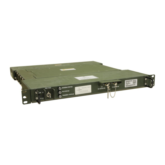
MPM-1000A Operator Manual 1000-7075 Rev E 3 CONTROLS AND INDICATORS This section covers the controls and indicators of the Modem. Verify the connections listed below prior to powering the Ruggedized Modem. Panel Indicators The front panel of the Ruggedized Modem contains one (1) power switch, three (3) Light Emitting Diode (LED) Modem status indicators and two (2) L-Band Monitor ports. -
Page 24: Table 3-1 Modem Panels
MPM-1000A Operator Manual 1000-7075 Rev E Table 3-1 Modem Panels Item Name Description Front Panel On/Off Switch Clear/White – Modem is initializing/running Built-in-Test Modem Status Light Emitting Diode (LED) (BIT). Green – No active faults, ready for operation. Red – Active fault is present. -
Page 25: Software Installation
MPM-1000A Operator Manual 1000-7075 Rev E 4 SOFTWARE INSTALLATION This section details procedures for installing the HCI software on the CDU PC and the Modem software on the and Modem. Procedures for uninstalling the software as well as installing software updates for the PC are addressed in Section 14.1. -
Page 26: Hci Software Installation Procedure
MPM-1000A Operator Manual 1000-7075 Rev E HCI Software Installation Procedure Prior to beginning software installation, ensure you have the following items available: CD-ROM with NetFramework1.1Runtime.exe and latest version of HCI software System configured as indicated in Section 4.1 with system administrator... -
Page 27: Human Computer Interface
MPM-1000A Operator Manual 1000-7075 Rev E NOTE The CDU port (J2) of the Modem has a default IP address of 192.0.1.2. The PC running the HCI must be on the same subnet (192.0.1.xxx) when connected to the CDU port. 2) In Subnet mask, type in <255.255.255.0>. -
Page 28: Human Computer Interface Familiarization
MPM-1000A Operator Manual 1000-7075 Rev E Figure 4-3 Select Mode Human Computer Interface Familiarization The Modem HCI is a Microsoft Windows GUI that enables the user to configure the Modem for operation in a Satellite Terminal system and visually monitor the status of the system during operation. -
Page 29: Software Version Screen
MPM-1000A Operator Manual 1000-7075 Rev E The HW, COMM, TRANSEC and Term Cal status boxes at the left-hand side of the screen show summary fault status of the Modem, communication channel status, calibration status and TRANSEC keying. The Alarm ACK button will acknowledge one (1) alarm at a time, starting with the oldest alarm. -
Page 30: Modem Cdu Port Ip Address
MPM-1000A Operator Manual 1000-7075 Rev E confirm your software version and ensure you have appropriate documentation and software drivers loaded for your system. Access the screen by clicking Software → Version. Figure 4-6 Software Menu The list displayed shows the versions of software resident in the Modem, the current version of the HCI, and the loaded configuration file (if any). -
Page 31: Figure 4-7 Configure Menu Tab
MPM-1000A Operator Manual 1000-7075 Rev E Figure 4-7 Configure Menu Tab b. Set the IP address for the Modem‟s CDU Port. (See Figure 4-8) c. Click Save. d. Cycle power to reboot the Modem. CAUTION If the CDU port address is changed and the PC can no longer talk to the CDU port, the Modem may be rendered inoperable. -
Page 32: Installation And Update Procedure - Modem
MPM-1000A Operator Manual 1000-7075 Rev E 4.10 Installation and Update Procedure – Modem Perform the following steps to install new software on the Modem. This procedure requires a HCI currently running on the PC and assumes the Terminal is disconnected from any network. -
Page 33: Figure 4-10 Select Mode Screen
MPM-1000A Operator Manual 1000-7075 Rev E 2) Select Maintenance and then click OK. (See Figure 4-10) Figure 4-10 Select Mode Screen 3) Wait until the Modem has completed initializing Maintenance Mode (a pop-up screen will say “Terminal Initializing…) Wait to proceed with step 4. -
Page 34: Figure 4-12 Software Download Showing Selected File
MPM-1000A Operator Manual 1000-7075 Rev E Figure 4-12 Software Download Showing Selected File Figure 4-13 Open Screen to Select Software to Download 6) Highlight the desired file and click Open. The pop-up window will close. (See Figure 4-13) 7) Click Start Download to launch the process. -
Page 35: Figure 4-14 Software Downloading Status
MPM-1000A Operator Manual 1000-7075 Rev E Figure 4-14 Software Downloading Status 8) When the status bar is filled and the data field indicates Verification OK, click the Software Rollover button. (Figure 4-15) Refer to Table 4-2 Software Download and Rollover for data descriptions for this window. -
Page 36: Figure 4-16 Software Rollover Start Screen
MPM-1000A Operator Manual 1000-7075 Rev E Figure 4-16 Software Rollover Start Screen 10) Click OK when the Software Rollover Result window appears stating Software Rollover Successful. (See Figure 4-17) Figure 4-17 Software Rollover Successful Screen 11) Once the Rollover has successfully completed and you select OK, the Terminal will automatically reboot. -
Page 37: Software Menu Overview
MPM-1000A Operator Manual 1000-7075 Rev E 5 SOFTWARE MENU OVERVIEW The following figures and tables describe the menus and functions available on the Modem HCI. This section will familiarize you with Modem capabilities and navigation. Launch Modem HCI After installing the Modem software, double-click the IPModemHCI icon located on the PC desktop. -
Page 38: Snmp Dialog
MPM-1000A Operator Manual 1000-7075 Rev E SNMP Dialog Figure 5-3 SNMP Mode Change shows the first screen to appear after selecting SNMP Configuration (Configure SNMP). Selecting No on this screen allows you to change SNMP parameters relevant to the current mode as shown in Figure 5-4 SNMP Configuration Dialog with the current mode set to V2. -
Page 39: Modes Of Operation
MPM-1000A Operator Manual 1000-7075 Rev E NOTE A Lost Connection Status Screen will appear; this error is because the Modem is rebooting. (See Figure 5-5) Figure 5-5 Connection Lost Status Screen Modes of Operation The primary interface for Monitor and Control of the Modem is an HCI GUI running on a PC that is attached via Ethernet to the Modem‟s CDU port. -
Page 40: Selecting Maintenance Mode
MPM-1000A Operator Manual 1000-7075 Rev E Figure 5-6 Select Mode Selecting Maintenance Mode a. Select Configure → Mode from the pull-down menu to launch the Select Mode screen. (See Figure 5-7) Figure 5-7 Configure Menu b. Select Maintenance. (See Figure 5-8) -
Page 41: System Shutdown
MPM-1000A Operator Manual 1000-7075 Rev E Figure 5-8 Select Mode Screen c. Select OK. Once the Modem has finished initializing the Maintenance Mode, the system will be in the Maintenance. System Shutdown NOTE Exiting the HCI does not terminate Modem operation. -
Page 42: File Pull-Down Menu
MPM-1000A Operator Manual 1000-7075 Rev E Figure 5-10 SCPC Main Screen To exit the HCI, select File Exit or click on the X at the upper right hand side of the window. You will be asked to confirm the operation. -
Page 43: Save/Save As Configuration
MPM-1000A Operator Manual 1000-7075 Rev E Table 5-1 File Configuration Item Functions Save Config Saves the active configuration using the same configuration description and file name. Save Config As Saves the active configuration using a new configuration description and file name. -
Page 44: Restore Configuration
MPM-1000A Operator Manual 1000-7075 Rev E Control/Indicator/Function Description Terminal Parameters Current Terminal parameters will be saved if selected. Satellite Parameters Current Satellite parameters will be saved if selected. NCW Parameters Current NCW parameters will be saved if selected. MIL-STD-188-165A Current 165A parameters will be saved if selected. -
Page 45: Figure 5-14 Open Configuration Dialog
MPM-1000A Operator Manual 1000-7075 Rev E Figure 5-14 Open Configuration Dialog c. Verify all settings to ensure that the correct configuration file has been selected. d. In the Modem Mode After Restore field, select which mode the Modem will operate in after the restore. -
Page 46: Figure 5-16 Confirm Restore Operation
MPM-1000A Operator Manual 1000-7075 Rev E f. Once the Restore button is selected, a Confirm Restore Operation widow will appear. (See Figure 5-15) g. Select Yes to restore the system. (See Figure 5-16) Figure 5-16 Confirm Restore Operation Once you click Yes, a status screen will appear to show the progress of the restore. -
Page 47: Configure Pull-Down Menu
MPM-1000A Operator Manual 1000-7075 Rev E Configure Pull-Down Menu Access this menu by clicking Configure. This menu links to pages and dialogs used to setup and operate the Modem. Some of the menu choices are on the Overall Status Screen as tabs. -
Page 48: Table 5-4 Configure Menu
MPM-1000A Operator Manual 1000-7075 Rev E Table 5-4 Configure Menu Description Control/Indicator/Function Network* This selection is mode dependent. When in the NCW mode, this item brings up the MIL-STD-188-EEE Page. It allows you to connect to the network, monitor network activity, and send or receive short messages. In the MIL-STD-188-165A mode, this item brings up the Modem Page. -
Page 49: Monitor Pull-Down Menu
MPM-1000A Operator Manual 1000-7075 Rev E 5.10 Monitor Pull-down Menu This menu provides links to the Alarms and Events screens. a. Select Monitor. (See Figure 5-18) b. Select appropriate item you wish to view. Figure 5-18 Monitor Menu 5-13... -
Page 50: System Configuration
MPM-1000A Operator Manual 1000-7075 Rev D 6 SYSTEM CONFIGURATION This section covers the configuration of the system. Configure System Screen This page controls Terminal specific parameters that are set on the initial installation. Once set, these parameters generally do not change. -
Page 51: Figure 6-2 System Configuration Screen
MPM-1000A Operator Manual 1000-7075 Rev D Figure 6-2 System Configuration Screen b. Edit Manual GPS Entry. 1) Enter in the Satellite dish‟s Latitude. 2) Enter Satellite dish‟s Longitude. 3) Enter Satellite dish‟s Altitude. 4) Select Apply. c. Edit Block Converter. -
Page 52: Configure Modem Screen
Block Converter Captures input of external block converter parameters, which must be entered when configuring an MPM-1000A. The Modem software uses the block converter frequencies and the satellite uplink and downlink frequencies to compute and set the Modem transmit and receive frequencies. -
Page 53: Satellite Setup
MPM-1000A Operator Manual 1000-7075 Rev D Table 6-2 Modem Screen Control/Indicator/Function Description Bandwidth Segment I/F Range Displays the computed range of I/F frequencies that the Modem will use based on the selected satellite bandwidth segment and the block up and down converters. -
Page 54: Beams List
MPM-1000A Operator Manual 1000-7075 Rev D Figure 6-4 Satellite List Screen Table 6-3 Satellite Database Description Control/Indicator/Function Satellite Entry/Update ** Name Satellite Name, ex – AMC-9 (ZeroTest is a keyword recognized by the software indicating that there is no satellite. Causes the software to set the round trip delay to 0 for testing). -
Page 55: Beam Edit Dialog
MPM-1000A Operator Manual 1000-7075 Rev D Figure 6-5 Beams List Screen Table 6-4 Beams List Control/Indicator/Function Description Allows the selected beam‟s parameters to be modified Edit button and brings up the Beam Edit dialog. Delete button Deletes the selected beam. -
Page 56: Bandwidth Segments List
MPM-1000A Operator Manual 1000-7075 Rev D Table 6-5 Edit Beam Dialog Control/Indicator/Function Description Six-character beam ID. (ex NCA6) Uplink and Downlink Receive and Transmit Polarity of the beam. Polarity Uplink and Downlink Band Frequency band of the uplink and the downlink. (Ka, Ku, C, or X) Uplink Center Frequency Center frequency of the uplink signal. -
Page 57: Bandwidth Segment Edit Dialog
MPM-1000A Operator Manual 1000-7075 Rev D Table 6-6 Bandwidth Segments Control/Indicator/Function Description Allows the selected bandwidth segment‟s parameters to be modified. Edit button (Select a line by clicking on the button to the left of the line). Delete button Deletes the selected bandwidth segment. -
Page 58: Figure 6-9 Edit Bandwidth Segment Dialog Using Saturated Flux Density
MPM-1000A Operator Manual 1000-7075 Rev D Refer to Table 6-7 Edit Bandwidth Segment for data descriptions for this window. Figure 6-9 Edit Bandwidth Segment Dialog using Saturated Flux Density... -
Page 59: Table 6-7 Edit Bandwidth Segment
MPM-1000A Operator Manual 1000-7075 Rev D Table 6-7 Edit Bandwidth Segment Control/Indicator/Function Description ID (1..63) of this bandwidth segment Uplink and Downlink Beam Beam ID of the beam containing this segments uplink frequency and beam containing this segments downlink. Beams selected from the Beams list. -
Page 60: Multiple Modem Configuration
MPM-1000A Operator Manual 1000-7075 Rev D Multiple Modem Configuration The multiple Modem configuration consists of a master Modem and up to five (5) slave modems (See Figure 6-10) linked together to increase the data throughput available at a node. This is also referred to as Modem Stacking or the Stack configuration. -
Page 61: Set The Mode Of The Modem
MPM-1000A Operator Manual 1000-7075 Rev D a. Connect PC and Master Modem to a network switch (not provided). b. Turn on the PC and the Modem. c. Once the Modem Status LED has turned green, open the HCI program. 6.4.2 Set the Mode of the Modem a. -
Page 62: Figure 6-13 Configure Drop Down Menu
MPM-1000A Operator Manual 1000-7075 Rev D a. Select Configure → IP Address Configuration. (See Figure 6-13) Figure 6-13 Configure Drop Down Menu b. Set the IP Address in CDU NEW to the desired network configurations. (See Figure 6-14) CAUTION Copy the CDU IP Address on a paper for future reference. If the CDU port address is changed and the PC can no longer talk to the CDU port, the Modem may be rendered inoperable. -
Page 63: Configure Slave Modem
MPM-1000A Operator Manual 1000-7075 Rev D Figure 6-14 IP Address Configuration Screen d. Click Save. e. A pop-up window will appear, select NO to keep the HCI at the default address. (See Figure 6-15) Figure 6-15 Change HCI to Modem Address f. -
Page 64: Figure 6-16 Configure Modem Screen
MPM-1000A Operator Manual 1000-7075 Rev D Figure 6-16 Configure Modem Screen f. Turn off Slave Modem. g. Repeat steps a through f for each additional slave. h. Turn on the Master Modem and wait for the Modem Status LED turns green. -
Page 65: Figure 6-17 Configure Drop Down Menu
MPM-1000A Operator Manual 1000-7075 Rev D Figure 6-17 Configure Drop Down Menu j. Click on the Master. Once the Master Modem has been highlighted, the Configure SLAVE Button will be active. (See Figure 6-18) Refer to Table 6-8 Multi-Modem Status Screen for data descriptions for this window. -
Page 66: Figure 6-19 Configure Slave Modem
MPM-1000A Operator Manual 1000-7075 Rev D Figure 6-19 Configure Slave Modem l. Set MPM Unit Id. Record the Unit Id and CDU IP address for use later in the procedure. m. Set the MASTER CDU Port IP. This is set to the Master Modem CDU IP address that the HCI connects to control the stack. -
Page 67: Figure 6-21 Configure Slave Modem
MPM-1000A Operator Manual 1000-7075 Rev D v. Select Add SLAVE. (See Figure 6-20) Add a Slave by matching the Unit ID and CDU IP Address you recorded earlier for each Slave (See Figure 6-21). All Slave statuses will remain red until the modems are changed from Maintenance Mode to NCW mode. -
Page 68: Figure 6-23 Wait For Secure Link Status
MPM-1000A Operator Manual 1000-7075 Rev D Figure 6-23 Wait for Secure Link Status Note Every Modem in the Multi-Modem configuration will show the Wait for Secure Link Status box. Once the MSK and Pass Phrase have been sent to each Modem, the status will turn green. -
Page 69: Table 6-8 Multi-Modem Status Screen
MPM-1000A Operator Manual 1000-7075 Rev D Table 6-8 Multi-Modem Status Screen Control/Indicator/ Description Function Name This field is used to identify the modems in a stacked Modem configuration. (i.e. D265, Nr1, ect.) CDU Port This field identifies the unique CDU Port IP Addresses associated with each Modem in a stacked Modem configuration. -
Page 70: Terminal Calibration
MPM-1000A Operator Manual 1000-7075 Rev D Terminal Calibration The Modem must be in either the NCW mode or Maintenance Mode in order to conduct the calibration. There are three methods to entering Terminal Calibration Data: File Entry Manual Entry Nominal Entry The File Entry method allows the user to enter data from a file. -
Page 71: Figure 6-26 Term Cal On Status Box
MPM-1000A Operator Manual 1000-7075 Rev D Figure 6-26 TERM CAL ON Status box c. On Gains Tab, select on File Entry under the PA Gain field of the Terminal Calibration. (See Figure 6-27) Figure 6-27 Terminal Calibration Screen d. Select the browse button (..) and a dialog window will open for you to select a file. -
Page 72: Figure 6-28 Calibration File Screen
MPM-1000A Operator Manual 1000-7075 Rev D Figure 6-28 Calibration File Screen e. Select the desired file to load. Files can contain data for all gain components of the system (BUC, PA, antenna) or a subset of these. In the event that the file only characterizes a subset of the gain components, only these sections of the Gain tab will be filled in. -
Page 73: Figure 6-30 Losses Screen
MPM-1000A Operator Manual 1000-7075 Rev D Figure 6-30 Losses Screen i. Select the browse button (..) and a dialog window will open for you to select a saved file. (See Figure 6-30) 6-24... -
Page 74: Manual Entry Method
MPM-1000A Operator Manual 1000-7075 Rev D Figure 6-31 Terminal Losses File Screen j. Select the desired “loss” file to load. (See Figure 6-31) k. Click Open and a File Validation Successful! Message pops up. (See Figure 6-32) Figure 6-32 File Validation Successful l. -
Page 75: Figure 6-34 Terminal Gains File Screen
MPM-1000A Operator Manual 1000-7075 Rev D Figure 6-34 Terminal Gains File Screen c. Select on New under the desired piece of equipment (PA Gain, BUC, Antenna Gain) of the Terminal Calibration. d. The Manual Entry screen will pop up. (See Figure 6-35) -
Page 76: Figure 6-35 Manual Entry Screen
MPM-1000A Operator Manual 1000-7075 Rev D Figure 6-35 Manual Entry Screen e. Enter in measured data in the particular field of the characterized piece of equipment (PA Gain, BUC Gain, Antenna Gain). f. Select Save when all desired data has been entered. -
Page 77: Figure 6-36 Losses Screen
MPM-1000A Operator Manual 1000-7075 Rev D Figure 6-36 Losses Screen j. Select OK and the Terminal Calibration window will close and all values will be pushed to the Modem‟s MIB. 6-28... -
Page 78: Nominal Value Method
MPM-1000A Operator Manual 1000-7075 Rev D 6.5.3 Nominal Value Method a. Select Configure → Terminal Calibration. (See Figure 6-37) Figure 6-37 Configure Menu b. Check the box Terminal Calibration State ON. (See Figure 6-38) c. Select on Nominal Entry Tab under the PA Gain and Antenna Gain field of the Terminal Calibration. -
Page 79: Figure 6-39 Losses Screen
MPM-1000A Operator Manual 1000-7075 Rev D e. Select Losses Tab. f. Select Use nominal values for losses. (See Figure 6-39) g. Enter in measured losses. Figure 6-39 Losses Screen h. Select OK and the Terminal Calibration window will close. 6-30... -
Page 80: Disable Terminal Calibration
MPM-1000A Operator Manual 1000-7075 Rev D Disable Terminal Calibration To disable the Terminal Calibration, uncheck Terminal Calibration State On selection Term Cal indicator on Main HCI will visually indicate Terminal Calibration status as OFF. (See Figure 6-41) Figure 6-40 Disable Terminal Calibration... -
Page 81: Transmission Security
MPM-1000A Operator Manual 1000-7075 Rev E 7 TRANSMISSION SECURITY This section covers the use of communications security (COMSEC) encryption for operational use of the system and is only available while in NCW mode. An External Encryption Device is required to operate in a secure network. The Modem does not have embedded encryption capability. -
Page 82: Figure 7-2 Transec Screen
MPM-1000A Operator Manual 1000-7075 Rev E Figure 7-2 TRANSEC Screen NOTE Zeroize not only wipes all loaded keys and key derived items, it also disables the Modem data port (J1). The Keys and Pass Phrases may be reloaded after a Zeroize, but to recover the data port, the Modem must have the power cycled. -
Page 83: Table 7-1 Transec Screen
MPM-1000A Operator Manual 1000-7075 Rev E Table 7-1 TRANSEC Screen Description Control/Indicator/Function Zeroize This button will Zeroize all keys and sensitive parameters in the local Terminal. Zeroize Remote* Allows you to Zeroize a remote Terminal from a list of logged-in Terminals. -
Page 84: Figure 7-3 Transec Screen
MPM-1000A Operator Manual 1000-7075 Rev E Figure 7-3 TRANSEC Screen c. Type in or paste in the hexadecimal key from a saved file that was provided by your Network Controller/Administrator into the New Current MSK pop-up box. (See Figure 7-4) Figure 7-4 New Current MSK Entry Screen d. -
Page 85: Figure 7-5 Msk Entry Status Screen
MPM-1000A Operator Manual 1000-7075 Rev E Figure 7-5 MSK Entry Status Screen f. Select Pass Phrase button. (See Figure 7-6) Figure 7-6 TRANSEC Pass Phrase Selection Screen g. A window will open; enter in pass phrase that was provided by your Network... -
Page 86: Figure 7-7 Pass Phrase Entry Screen
MPM-1000A Operator Manual 1000-7075 Rev E Figure 7-7 Pass Phrase Entry Screen h. Press the OK button. (See Figure 7-7) Wait up to 15 seconds for the Pass Phrase to be stored. Two (2) pop-ups will appear during the process. (See Figure... -
Page 87: Figure 7-9 Status Screen For Secure Link
MPM-1000A Operator Manual 1000-7075 Rev E Figure 7-9 Status Screen for Secure Link... -
Page 88: Network Control Operations
MPM-1000A Operator Manual 1000-7075 Rev E 8 NETWORK CONTROL OPERATIONS Network Overview The Modem is an IP-based Modem that implements the NCW specified by MIL-STD- 188-EEE. An NCW network is a full-mesh SATCOM network designed to support a group of terminals with varying antenna, power and overall transceiver characteristics –... -
Page 89: Network Controller Capable
MPM-1000A Operator Manual 1000-7075 Rev E control slots (FOW and ROW) interconnecting the NC and the NMs in the network. The NC manages, controls, and allocates the resources for the signaling and traffic communications within the network. It is anticipated that networks will be established around specific user communities having a common mission wherein resources will be allocated in accordance with mission requirements and data priority. -
Page 90: Ncw Signals
MPM-1000A Operator Manual 1000-7075 Rev E NCW Signals The NCW defines three (3) basic burst or slot types, each with specific functions of communication between NMs. Each burst type is further broken down into elements and fields that contain specific information: a. -
Page 91: Data Communications Burst (Dcom)
MPM-1000A Operator Manual 1000-7075 Rev E a. AROW: The assigned ROW slot is used by the NM to communicate back to the NC and request network resources. After login, each NM is assigned a time and frequency in which it must provide its AROW to the NC. This allocates an AROW slot in each frame and the NM is required to send this AROW each frame. -
Page 92: Network Initiation
MPM-1000A Operator Manual 1000-7075 Rev E Figure 8-2 shows how an NC will provide Orderwires and DCOM bursts to a NM. In the figure, time is shown along the bottom of the diagram, 0.40 seconds representing one frame, while assigned frequencies, called carriers (or channels), are shown in the depth (z-axis) of the diagram. - Page 93 MPM-1000A Operator Manual 1000-7075 Rev E Terminal usage and Satellite resources by using a large set of adaptive data-rates (in approximately 1.5 dB steps), code-rates, modulation types, spread factors, adaptive power-control (in 0.25 dBW increments) and the use of multiple simultaneous transmitters and receivers at each Terminal.
-
Page 94: Network Operation With Wideband Global Satellite
MPM-1000A Operator Manual 1000-7075 Rev E Accurate Terminal and Satellite parameters are required to compute accurate path losses and to predict an accurate total C/No value for a link. Accurate Terminal parameters and settings are required so that a Terminal commanded to transmit at a given power level implements exactly that power level. - Page 95 MPM-1000A Operator Manual 1000-7075 Rev E different beams, then the fully fanned-out group of bandwidth segments from their respective beams must also be fanned-in such that on the downlink they arrive in a common bandwidth segment within each beam. This fully fanned-...
-
Page 96: Setting The Terminal For Ncw Mode As Network Controller
MPM-1000A Operator Manual 1000-7075 Rev E NCW resource scheduler initially attempts to place the burst within bandwidth segments that provide the required spatial connectivity and whose uplink EIRP range encompasses the EIRP of the source terminal and downlink G/T range encompasses the G/T of the destination terminal. -
Page 97: Figure 8-4 Ncw Parameters Tab
MPM-1000A Operator Manual 1000-7075 Rev E Figure 8-4 NCW Parameters Tab 2) In the Terminal Type, select Network Controller Capable. 3) Select Apply button to save current settings. b. Select the TRANSEC Tab on the Overall Status Screen. Refer to Section 7 Transmission Security. -
Page 98: Ncw Network
MPM-1000A Operator Manual 1000-7075 Rev E NCW Network Page Tabs The tabs displayed on the Network page provide you access to network statistics that can be used to help troubleshoot network communication problems. You can access the Network page by selecting Configure → Network, or the Network button. -
Page 99: Table 8-1 Ncw Network Tab
MPM-1000A Operator Manual 1000-7075 Rev E Table 8-1 NCW Network Tab Description Control/Indicator/Function Node Name Displays the Node name assigned to the Terminal. Node name can be changed from the NCW Setup page. Status Displays the connect status of the Terminal. -
Page 100: Ncw Message Tab
MPM-1000A Operator Manual 1000-7075 Rev E 8.7.2 NCW Message Tab This page repeats the Terminal list from the Network page and shows the log of messages sent and received. Right-click on an entry in the Network Terminal List to bring up the Send Message dialog. Each message allows a maximum of 255 characters. -
Page 101: Table 8-2 Ncw Message Tab
MPM-1000A Operator Manual 1000-7075 Rev E Table 8-2 NCW Message Tab Description Control/Indicator/Function Node Name Displays the Node name of this Terminal. Status Displays the connect status of this Terminal. Role Indicates the current role of the Terminal NM NCC. -
Page 102: Ncw Statistics Tab
MPM-1000A Operator Manual 1000-7075 Rev E 8.7.3 NCW Statistics Tab This page provides statistics of network operation. Only Terminals that are NCC will display AROW statistics. For NM Only Terminals there will be a blank space. For each type of burst, the Modem provides information on acquisition performance and error (bad Cyclic Redundancy Code (CRC)) performance. -
Page 103: Table 8-3 Ncw Statistics Tab
MPM-1000A Operator Manual 1000-7075 Rev E Table 8-3 NCW Statistics Tab Control/Indicator/Function Description Reference FOW The statistics shown represent the number of failed burst acquisition attempts versus the number of bursts assigned, as well as the number of bursts with CRC failures versus number of bursts successfully acquired. -
Page 104: Ncw Bw/Eirp Tab
MPM-1000A Operator Manual 1000-7075 Rev E 8.7.4 NCW BW/EIRP Tab This NC only page provides Satellite BW and EIRP statistics for the network. This shows you the average amount of the Satellite resources being used and the peak usage since the last reset. -
Page 105: Table 8-4 Ncw Bw/Eirp Tab
MPM-1000A Operator Manual 1000-7075 Rev E Table 8-4 NCW BW/EIRP Tab Control/Indicator/Function Description Satellite Bandwidth and EIRP Utilization Bandwidth Segment ID This is the ID (1...63) of the BW segment. See the Satellite entry for a description of BW segments. -
Page 106: Ncw Path Loss Tab
MPM-1000A Operator Manual 1000-7075 Rev E 8.7.5 NCW Path Loss Tab This NC only page provides Path Loss statistics for the network. The NC automatically applies adaptive data-rate and power control to accommodate changing link quality conditions. This page allows you to monitor the fade conditions in the network. -
Page 107: Table 8-5 Ncw Path Loss Tab
MPM-1000A Operator Manual 1000-7075 Rev E Table 8-5 NCW Path Loss Tab Control/Indicator/Function Description Path Loss Terminal Node Name Node Name of the Terminal in the network. This page only shows logged in Terminals. Clear Sky Uplink This is the predicted clear sky uplink loss based on uplink and downlink frequencies, the Satellite location and the Terminal location. -
Page 108: Ncw Rx Burst Tab
MPM-1000A Operator Manual 1000-7075 Rev E 8.7.6 NCW RX Burst Tab This page provides receive burst statistics for the network. It details the performance from each logged-in Terminal (including the NC) in the network. In order to identify particular NCW links that are having communication problems, each network Terminal records burst statistics for all received messages that have been successfully decoded at the Terminal. -
Page 109: Table 8-6 Ncw Rx Burst Tab
MPM-1000A Operator Manual 1000-7075 Rev E Table 8-6 NCW RX Burst Tab Control/Indicator/Function Description Reference FOW Source Name Name of the NC Terminal transmitting these bursts. FOW Acquisition (ACQ)s This is a count (since the last reset) of the number of missed FOW bursts along with the number of expected FOW bursts. -
Page 110: Ncw Rx Comm Tab
MPM-1000A Operator Manual 1000-7075 Rev E 8.7.7 NCW RX Comm Tab This page provides receive DCOM statistics for the network Terminals. Note that a Terminal does not receive its own DCOM bursts, so the Terminal making this report will not appear in the list of Sources. - Page 111 MPM-1000A Operator Manual 1000-7075 Rev E Hint on Hub Assist Statistics: The hub-assist statistics work as follows: Terminals A, B, and H are present on the network. Terminal A is transmitting data to Terminal B; hub-assisted is through Terminal H. A review of the specific terminals displays the following: At Terminal A‟s TX Comm statistics, the HCI populates the values for...
-
Page 112: Ncw Tx Comm Tab
MPM-1000A Operator Manual 1000-7075 Rev E 8.7.8 NCW TX Comm Tab This page provides transmit communications statistics for the network Terminals. Note that Terminals do not transmit to themselves, but do transmit to the Broadcast address. Refer to Table 8-8 NCW TX Comm Tab for data descriptions for this window. -
Page 113: Ncw Tx Queue Tab
MPM-1000A Operator Manual 1000-7075 Rev E 8.7.9 NCW TX Queue Tab This page provides transmit queue depth statistics by network Terminal and by DiffServ Code Point. The HCI displays the queue depths in bytes and it refreshes the display once per second (unless Paused). -
Page 114: Ncw Link Budget Tab
MPM-1000A Operator Manual 1000-7075 Rev E 8.7.10 NCW Link Budget Tab This NC only page provides a link budget calculator that can be used to estimate the burst information rate that can be achieved directly (peer-to-peer) between a particular source and destination Terminal. -
Page 115: Ncw Setup Tabs
MPM-1000A Operator Manual 1000-7075 Rev E NCW Setup Tabs The tabs displayed in the Network Centric Waveform Setup screen allow you to view settings. Generally, these fields are set to defaults and should not be changed unless directed by the Network Administrator. To view this page (Configure → Network Centric Waveform Setup →... -
Page 116: Table 8-11 Ncw Setup Parameters Tab
MPM-1000A Operator Manual 1000-7075 Rev E Table 8-11 NCW Setup Parameters Tab Control/Indicator/Function Description Modem Node Name Node name for this Satellite Terminal in the network. The name must be unique and consist of less than 13 alphanumeric characters. Transmit gain of the Terminal from the Modem‟s TX IF output through the Transmit Chain Gain Factor antenna. -
Page 117: Ncw Advanced Tab
MPM-1000A Operator Manual 1000-7075 Rev E 8.8.2 NCW Advanced Tab This page allows fine-tuning on how the network scheduler reacts to changes in the network. Refer to Table 8-12 NCW Setup Advanced Tab for data descriptions for this window. Figure 8-16 NCW Setup Advanced Tab... - Page 118 MPM-1000A Operator Manual 1000-7075 Rev E Table 8-12 NCW Setup Advanced Tab (Cont’d) Control/Indicator/Function Description Non Delay-Sensitive Hub The data rate at which hub-assisted communication is invoked for non Assist Data Rate delay-sensitive traffic. If the peer-to-peer link data rate does not meet this specified rate, then hub-assistance (two-hop) communication is invoked for non delay-sensitive traffic.
-
Page 119: Ncw Qos Tab
MPM-1000A Operator Manual 1000-7075 Rev E 8.8.3 NCW QOS Tab This screen allows customizing the mapping between the type of service (TOS) field on IP packets, and the priority they will have on the NCW controlled Satellite network. Refer to Table 8-13 NCW QOS Tab for data descriptions for this window. -
Page 120: Figure 8-18 Edit Qos Entry Dialog (Qos Tab)
MPM-1000A Operator Manual 1000-7075 Rev E Figure 8-18 Edit QOS Entry Dialog (QOS Tab) This screen appears after selecting the Add or Edit button on the QoS tab. See Table 8-13 for a description of the input/edit fields. 8-33... -
Page 121: Ncw Psd Tab
MPM-1000A Operator Manual 1000-7075 Rev E 8.8.4 NCW PSD Tab You use this screen to Add, Delete or Edit data entries within the Antenna Beamwidth versus Power Spectral Density (PSD) table in degrees of Antenna Beamwidth and associated PSD in dBW/Hz. To enable/disable Spread Spectrum Operations refer to the Satellite Beam Entry Section (6.3.4). -
Page 122: Figure 8-20 Antenna Beamwidth Vs. Power Spectral Density
MPM-1000A Operator Manual 1000-7075 Rev E Table 8-14 NCW PSD Tab Control/Indicator/Function Description Antenna Beamwidth Power Spectral Density Settings Beamwidth (deg) Antenna Beamwidth in degrees. Values between 0.00 and 10.00 can be entered. PSD (dBW/Hz) Power Spectral Density entry in dBW/Hz. Values between -50.00 and 0.00 can be entered. -
Page 123: Network Member Operations
MPM-1000A Operator Manual 1000-7075 Rev E 9 NETWORK MEMBER OPERATIONS This section covers the setup of the Modem to operate as a NM. Setting the Terminal for NCW Mode as a Network Member a. Select Configure → Network Centric Waveform Setup. (See Figure 9-1) -
Page 124: Ncw Network Member Tabs
MPM-1000A Operator Manual 1000-7075 Rev E Figure 9-2 NCW Parameters Tab 2) In the Terminal Type, select Net Member Only. (See Figure 9-2) 3) Select Apply button to save current settings. (See Figure 9-2) b. Select the TRANSEC Tab on the Overall Status Screen. Refer to Section 7 Transmission Security. -
Page 125: Figure 9-3 Ncw Network Tab
MPM-1000A Operator Manual 1000-7075 Rev E Figure 9-3 NCW Network Tab Table 9-1 NCW Network Tab Control/Indicator/Function Description Node Name Displays the Node name assigned to the Terminal. Node name can be changed from the NCW Setup page. Status Displays the connect status of the Terminal. - Page 126 MPM-1000A Operator Manual 1000-7075 Rev E Table 9-1 NCW Network Tab (Cont’d) Control/Indicator/Function Description Protocol Status Displays network operation status messages. Right click mouse within Protocol Status list, selecting “Clear” from menu Clear Status List* will clear the log from the displayed list.
-
Page 127: Ncw Message Tab
MPM-1000A Operator Manual 1000-7075 Rev E 9.2.2 NCW Message Tab This page repeats the Terminal list from the Network page and shows the log of messages sent and received. Right-click on an entry in the Network Terminal List to bring up the Send Message dialog. Each message allows a maximum of 255 characters. -
Page 128: Table 9-2 Ncw Message Tab
MPM-1000A Operator Manual 1000-7075 Rev E Table 9-2 NCW Message Tab Description Control/Indicator/Function Node Name Displays the Node name of this Terminal. Status Displays the connect status of this Terminal. Role Indicates the current role of the Terminal NM NCC. -
Page 129: Ncw Statistics Tab
MPM-1000A Operator Manual 1000-7075 Rev E 9.2.3 NCW Statistics Tab This page provides statistics of network operation. MIL-STD-188-EEE defines three (3) types of bursts. For more information, refer to Section 8.2. For each type of burst, the Modem provides information on acquisition performance and error (bad CRC) performance. -
Page 130: Table 9-3 Ncw Statistics Tab
MPM-1000A Operator Manual 1000-7075 Rev E Table 9-3 NCW Statistics Tab Control/Indicator/Function Description Reference FOW The statistics shown represent the number of failed burst acquisition attempts versus the number of bursts assigned, as well as the number of bursts with CRC failures versus number of bursts successfully acquired. -
Page 131: Ncw Rx Burst Tab
MPM-1000A Operator Manual 1000-7075 Rev E 9.2.4 NCW RX Burst Tab This page provides receive burst statistics for the network. It details the performance from each logged-in Terminal (including the NC) in the network. In order to identify particular NCW links that are having communication problems, each network Terminal records burst statistics for all received messages that have been successfully decoded at the Terminal. -
Page 132: Table 9-4 Ncw Rx Burst Tab
MPM-1000A Operator Manual 1000-7075 Rev E Table 9-4 NCW RX Burst Tab Control/Indicator/Function Description Reference FOW Source Name Name of the Network Control Terminal transmitting these bursts. FOW ACQs This is a count (since the last reset) of the number of missed FOW bursts along with the number of expected FOW bursts. -
Page 133: Ncw Rx Comm Tab
MPM-1000A Operator Manual 1000-7075 Rev E 9.2.5 NCW RX Comm Tab This page provides received DCOM statistics for the network Terminals. Note that a Terminal does not receive its own DCOM bursts, so the Terminal making this report will not appear in the list of Sources. - Page 134 MPM-1000A Operator Manual 1000-7075 Rev E Hint on Hub Assist Statistics: The hub-assist statistics work as follows: Terminals A, B, and H are present on the network. Terminal A is transmitting data to Terminal B; hub-assisted through Terminal H. A review of the specific terminals displays the following: At Terminal A‟s TX Comm statistics, the HCI populates the values for...
-
Page 135: Ncw Tx Comm Tab
MPM-1000A Operator Manual 1000-7075 Rev E 9.2.6 NCW TX Comm Tab This page provides transmit communications statistics for the network Terminals. Note that Terminals do not transmit to themselves, but do transmit to the Broadcast address. Refer to Table 9-6 NCW TX Comm Tab for data descriptions for this window. -
Page 136: Ncw Tx Queue Tab
MPM-1000A Operator Manual 1000-7075 Rev E 9.2.7 NCW TX Queue Tab This page provides transmit queue depth statistics by network Terminal and by DiffServ code point. The HCI displays the queue depths in bytes and it refreshes the display once per second (unless Paused). -
Page 137: Ncw Setup Tabs
MPM-1000A Operator Manual 1000-7075 Rev E NCW Setup Tabs The tab displayed in the NCW Setup screen allows you to view settings. Generally, these fields are set to defaults and should not be changed. To view this page (Configure → NCW → Parameters). -
Page 138: Table 9-8 Ncw Parameters Tab
MPM-1000A Operator Manual 1000-7075 Rev E Table 9-8 NCW Parameters Tab Control/Indicator/Function Description Modem Node Name Node name for this Satellite Terminal in the network. The name must be unique and consist of less than 13 alphanumeric characters. Transmit gain of the Terminal from the Modem‟s TX IF output through the Transmit Chain Gain Factor antenna. -
Page 139: Ncw Advanced Tab
MPM-1000A Operator Manual 1000-7075 Rev E 9.3.2 NCW Advanced Tab This page sets parameter for the local terminal operations.. Refer to Table 9-9 NCW Advanced Tab for data descriptions for this window. Figure 9-11 NCW Advanced Tab Table 9-9 NCW Advanced Tab... -
Page 140: Ncw Qos Tab
MPM-1000A Operator Manual 1000-7075 Rev E 9.3.3 NCW QOS Tab This screen allows customizing the mapping between the type of service (TOS) field on IP packets and the priority they will have on the NCW controlled satellite network. Refer to Table 9-10 NCW QOS Tab for data descriptions for this window. -
Page 141: R2Cp Network Operations
MPM-1000A Operator Manual 1000-7075 Rev E 10 R2CP NETWORK OPERATIONS The Radio-Router Control Protocol (R2CP) feature allows a local Modem to provide information to its local data router (“local router”) about each of the radio links to remote Modems for both Unicast and Multicast DCOM traffic. -
Page 142: Table 10-1 R2Cp Config Tab
MPM-1000A Operator Manual 1000-7075 Rev E Table 10-1 R2CP Config Tab Control/Indicator/ Description Function Update This box indicates that the R2CP sessions have changed. To update the R2CP session, see section 10.2. R2CP Error This indicates an Error has been written to a trap File. See section 1. - Page 143 MPM-1000A Operator Manual 1000-7075 Rev E Table 10-1 R2CP Config Tab (Cont’d) Control/Indicator/ Description Function Smooth Factor The weighting factor employed in the weighted recursive exponential filter, used to smooth the maximum data rate on a per-destination basis. Default is 10.
-
Page 144: R2Cp Session Tab
MPM-1000A Operator Manual 1000-7075 Rev E 10.2 R2CP Session Tab The session display shows multiple rows. Each row represents a possible destination for data flow from this NCW node. A destination can be a single node (Unicast), multiple nodes (Multicast) or all nodes (broadcast). -
Page 145: R2Cp Operational State
MPM-1000A Operator Manual 1000-7075 Rev E Table 10-2 R2CP Sessions Tab (Cont’d) Control/Indicator/ Description Function RLQ [%] Ratio of Mean Out Bit Rate to Mean In Bit Rate. Update Button You should right-click on the update button refresh the session display with data from the Modem. -
Page 146: Pim Snooping And Multicast
MPM-1000A Operator Manual 1000-7075 Rev E 10.4 PIM Snooping and Multicast The Modem is able to snoop Protocol Independent Multicast (PIM) version 2 (PIMv2) packets and automatically establish NCW corresponding multicast groups. “Snooping” is the process of a protocol layer observing the contents of an upper layer protocol, and taking action. -
Page 147: Table 10-4 Multicast Config Tab
MPM-1000A Operator Manual 1000-7075 Rev E Table 10-4 Multicast Config Tab Control/Indicator/ Description Function PIM Snoop Enable Controls whether PIM snooping is enabled or disabled. When PIM snooping is enabled, the NC dynamically establishes NCW multicast groups based on snooped PIM packets. The default value is disabled. -
Page 148: Adding To The Pim Stateless Group List
MPM-1000A Operator Manual 1000-7075 Rev E 10.6 Adding to the PIM Stateless Group List The PIM Stateless Group list allows you to specific Ethernet multicast MAC addresses that are disallowed from establishing NCW multicast group addresses. Enter an Ethernet MAC address in the following format: six 2-digit hexadecimal numbers separated by „-„. -
Page 149: Group Status
MPM-1000A Operator Manual 1000-7075 Rev E 10.7 Group Status The Group Status window displays the status of all dynamically established multicast groups. It includes a mapping of Ethernet multicast MAC addresses to NCW multicast group addresses and, for each NCW group, a list of group members identified by node mnemonic. -
Page 150: Table 10-6 Group Status Tab
MPM-1000A Operator Manual 1000-7075 Rev E Table 10-6 Group Status Tab Control/Indicator/ Description Function Group Directory The current NCW Group Directory. Each entry in the table maps an Ethernet Table multicast MAC address (as identified by PIM snooping) to a NCW multicast group address. -
Page 151: Scpc Network Operations
MPM-1000A Operator Manual 1000-7075 Rev E 11 SCPC NETWORK OPERATIONS This is the Network screen when in the SCPC mode of operation. The controls in the TX Power box are immediate action controls. The HCI highlights all other controls that you can change. -
Page 152: Figure 11-3 Mil-Std-188-165A Configure Screen
MPM-1000A Operator Manual 1000-7075 Rev E Refer to Table 11-1 MIL-STD-188-165A Configure Parameters for data descriptions for this window. Figure 11-3 MIL-STD-188-165A Configure Screen 11-2... -
Page 153: Table 11-1 Mil-Std-188-165A Configure Parameters
MPM-1000A Operator Manual 1000-7075 Rev E Table 11-1 MIL-STD-188-165A Configure Parameters Item Description Satellite In Use Select Satellite to use. BW Seg In Use BW Segment of the Satellite to use. Modulator (TX): Modulation Select waveform modulation. Data Rate Specify data rate (bps). -
Page 154: Preventive Maintenance Checks And Services (Pmcs)
MPM-1000A Operator Manual 1000-7075 Rev E 12 PREVENTIVE MAINTENANCE CHECKS AND SERVICES (PMCS) 12.1 Introduction PMCS are the checks, services and maintenance performed to maintain the Modem in optimal safe and operational condition. Performing a PMCS check every time the equipment is used will contribute to high level of serviceability and operational availability. -
Page 155: Cleaning
MPM-1000A Operator Manual 1000-7075 Rev E bolt and screw heads and nuts. Wire brush, sand or otherwise neutralize corrosion and retouch paint. c. Welds: The cases of the chassis are welded. To check these welds, look for chipped paint, rust, corrosion or gaps. If these conditions are found, document and notify your supervisor. -
Page 156: Table 12-1 Operator Preventive Maintenance Checks And Services (Pmcs)
MPM-1000A Operator Manual 1000-7075 Rev E NOTE Perform monthly PMCS once a month: If the system has not been operated in a month, perform daily PMCS at the same time. Perform both daily and monthly PMCS: If operating the system for the first time. -
Page 157: Troubleshooting
MPM-1000A Operator Manual 1000-7075 Rev E 13 TROUBLESHOOTING This section covers the basic troubleshooting of the system and briefly reviews setting audible alerts for alarms. 13.1 Introduction Troubleshooting procedures described in this manual emphasize the concept of performance monitoring and signal path testing through Built in Test (BIT) and logical flow. -
Page 158: Troubleshooting Tables
MPM-1000A Operator Manual 1000-7075 Rev E Table 13-1 BIT Status Troubleshooting Indicator Location Status Description Clear – Modem is off or measuring internal functions. Status LED Front panel, top Green – Internal modules/functions working normally; communications with PC established. Red – Modem has failed boot process parameters or there is an active alarm. - Page 159 MPM-1000A Operator Manual 1000-7075 Rev E Table 13-2 General Troubleshooting Symptom Description Probable Cause Corrective Action No front panel No Power or Loss of input Check power cord, check electrical outlet. lights. Status power. indications. Replace Modem. Modem Power Supply bad.
- Page 160 MPM-1000A Operator Manual 1000-7075 Rev E Table 13-2 General Troubleshooting (Cont’d) Symptom Description Probable Cause Corrective Action RFOW not Check to make sure you have the correct RFOW Spread RFOW Spread Factor (Configure found. Factor does not Network Centric Waveform Setup) match the NC.
- Page 161 MPM-1000A Operator Manual 1000-7075 Rev E Table 13-2 General Troubleshooting (Cont’d) Symptom Description Probable Cause Corrective Action Open System Configuration page and Unable to Transmit recheck system parameters. and Receive. Check to see if the Modem has been logged off the satellite network, if logged off re-enter the active network.
- Page 162 MPM-1000A Operator Manual 1000-7075 Rev E Table 13-2 General Troubleshooting (Cont’d) Symptom Description Probable Cause Corrective Action Unable to gain Insufficient BW to Increase the satellite BW segment BW or Reference FOW RFOW value. decrease the RFOW spread factor. schedule RFOW.
-
Page 163: Alarms/Events
MPM-1000A Operator Manual 1000-7075 Rev E 13.5 Alarms/Events Alarms and events are used to monitor and assist with troubleshooting the system. These should be set at the direction of a system administrator. Only a brief overview of the Modem capabilities is provided here for reference. -
Page 164: Events Screen
MPM-1000A Operator Manual 1000-7075 Rev E Figure 13-2 Alarm Sound Audible Setting Screen 13.5.2 Events Screen This screen displays a list of alarm events. When it reaches 1000 entries, these entries are automatically deleted beginning with the oldest event. For maintenance purposes, it is recommended this list be archived regularly. -
Page 165: Active Alarms
MPM-1000A Operator Manual 1000-7075 Rev E Refer to Events for data descriptions for this window. Figure 13-3 Events Screen Table 13-1 Events Events Functions Check All Selects all events. Select individual events by clicking the check box in the Sequence column. -
Page 166: Assistance
MPM-1000A Operator Manual 1000-7075 Rev E Figure 13-4 Antenna Active Alarm Screen 13.6 Assistance For further assistance, or if factory service appears necessary, contact L-3 Communications-Linkabit Group customer service using the contact information at the front of this manual. 13-10... -
Page 167: Maintenance
MPM-1000A Operator Manual 1000-7075 Rev E 14 MAINTENANCE This section covers the basic authorized maintenance of the system. If a software update is recommended or necessary, contact L-3 Communications-Linkabit Group customer service using the contact information at the front of this manual. The Product Manager will authorize access to a secure website where software updates and accompanying documentation may be downloaded. -
Page 168: Modem Stacking Installation
MPM-1000A Operator Manual 1000-7075 Rev E 14.2 Modem Stacking Installation The design of the Modem allows multiple Modems to be tied together as a single virtual Modem. The minimum number of Modems is two (2) and the maximum number of modems is six (6). -
Page 169: Figure 14-2 Modem Stacking Interconnect Diagram
MPM-1000A Operator Manual 1000-7075 Rev E External Router Reference Data Ref In Tx IF RM #1 (Master) Rx IF FrameStrobe Ref Out J6 (30,31) Terminal Tx IF Data Ref In Tx IF Combiner RM #2 (Slave) Rx IF FrameStrobe Ref Out... -
Page 170: Maintenance Specifications
MPM-1000A Operator Manual 1000-7075 Rev E 14.3 Maintenance Specifications The following specifications are provided for maintenance or alternative configuration purposes. This information is only provided for reference. For questions on the specifications or alternative configuration setup, contact the L-3 Communications Linkabit Product Manager. -
Page 171: Table 14-1 Rear Panel Connection Specifications Overview
MPM-1000A Operator Manual 1000-7075 Rev E Table 14-1 Rear Panel Connection Specifications Overview Item Name Description RX MON OUT RX IF Frequency Range: 950 MHz to 2150 MHz (L-Band) Output ImpedanceA:50Ω nominal with VSWR <1.5:1 TX MON OUT TX IF Frequency Range: 950 MHz to 2150 MHz (L-Band) TX IF Output. -
Page 172: External Signal Pin Assignments
MPM-1000A Operator Manual 1000-7075 Rev E 14.3.2 External Signal Pin Assignments Panel Connector – External Interfaces 14.3.2.1 The Modem will accept and synchronize to a 5-MHz or 10-MHz sinusoidal reference signal source. The Modem is capable of operating without an external reference frequency. -
Page 173: Table 14-4 Tx Intermediate Frequecy Output Interface
MPM-1000A Operator Manual 1000-7075 Rev E Table 14-4 TX Intermediate Frequecy Output Interface CONN Signal Name Input/Output Signal Description TX IF Output TX IF Frequency Range: 950 MHz to 2150 MHz COAX with 10 MHz (L-Band) TX IF Output. -40 dBm to 0 dBm (L-Band across 50Ω... -
Page 174: Table 14-6 Modem Rx Intermediate Frequency Input Interface
MPM-1000A Operator Manual 1000-7075 Rev E Table 14-6 Modem RX Intermediate Frequency Input Interface CONN Signal Name Input/Output Signal Description RX IF Input/Output RX IF Frequency Range: 950 MHz to 2150 MHz COAX (L-Band) RX IF Output Signal Level: -77 dBm to -15 dBm individual carries across 50Ω;... -
Page 175: Table 14-8 Control, Monitor And Alarm Ethernet Interface
MPM-1000A Operator Manual 1000-7075 Rev E The particular MIB file corresponding to an MPM-1000 software version can be found with the released software. Table 14-8 Control, Monitor and Alarm ETHERNET Interface CONN Signal Name Input/Output Signal Description Output 10/100/1000BASE-T Tx+ Ethernet port... -
Page 176: Table 14-10 Scpc Baseband Interface
MPM-1000A Operator Manual 1000-7075 Rev E This interface is located on the rear panel J5 connector. Table 14-10 SCPC Baseband Interface CONN Signal Name Input/Output Signal Description SHIELD Input SHIELD TX DATA A Input Balanced, RS-422 Tx Data signal terminated with... -
Page 177: Table 14-11 Secure Voice Baseband Interface
MPM-1000A Operator Manual 1000-7075 Rev E 14.3.2.10 Secure Voice Baseband Interface For Network Centric operation, the Modem provides an interface for externally encrypted secure voice baseband with the electrical interfaces defined in Table 14-11. The interface is interoperable with MIL-STD-188-114 balanced and unbalanced standard. -
Page 178: Table 14-12 Terminal Devices Interface
MPM-1000A Operator Manual 1000-7075 Rev E The configuration options of the Terminal Control and Monitoring Interface are as follows: Unbalanced signaling mode* Balanced half-duplex (HD) RS-485, and Balanced full-duplex (FD) RS-422/RS-485 *Note: Unbalanced signaling mode output voltage swing is 0 to +5V. The input signal voltage range is -7V to +12V. - Page 179 MPM-1000A Operator Manual 1000-7075 Rev E Table 14-12 Terminal Devices Interface (cont’d) CONN Signal Name Input/Output Signal Description CNTRL TX Output Not used in unbalanced mode; Positive node of DATA 2A HD RS-485; TXD+ of FD RS-422/RS-485 CNTRL TX Output TXD in unbalanced mode;...
-
Page 180: Table 14-13 Power Input Interface
MPM-1000A Operator Manual 1000-7075 Rev E 14.3.2.14 Power Input Interface The Modem operates with input voltage ranges of 90-132 VAC (110 VAC nominal) and 180-264 VAC (220 VAC nominal) and input frequency from 47 Hz to 63 Hz. The Modem supports AC input auto ranging. -
Page 181: Table 14-15 Rs-485 Scpc Control Interface
MPM-1000A Operator Manual 1000-7075 Rev E Table 14-15 RS-485 SCPC Control Interface CONN Signal Name Input/Output Signal Description MODEM Input Balanced RS-485 CNTRL RX A1 MODEM Input Balanced RS-485 CNTRL RX B1 MODEM Output Balanced RS-485 CNTRL TX A1 MODEM... -
Page 182: Appendix A - Network Transmission Security
MPM-1000A Operator Manual 1000-7075 Rev E 15 APPENDIX A – NETWORK TRANSMISSION SECURITY 15.1 Keying Scheme Figure 15-1 Overall Keying Scheme depicts the keying scheme used by the Modem in a NCW network. A “split-knowledge” keying concept is employed, wherein two (2) independent, externally supplied, keying parameters are required to produce the operational message encryption key material (MEKs). -
Page 183: Key Establishment
MPM-1000A Operator Manual 1000-7075 Rev E 15.2 Key Establishment Modem NCW seed keys are provided by the Army Key Management System (AKMS), or other authorized Government key generation facility. At the seed key generating location (AKMS workstation), a random Message Seed Key (MSK) is generated using a cryptographically strong randomizer. -
Page 184: Distribution
MPM-1000A Operator Manual 1000-7075 Rev E Figure 15-2 SSH Network Connection 15.4 Distribution Each Modem Terminal must manually load a current MSK and current TRANSEC Passphrase to initially join or establish a network. Both parameters are sensitive but unclassified and must not be disclosed to parties other than personnel responsible for generating the keys, and authorized system managers and operators. -
Page 185: Changeover Transec Passphrase Distribution
MPM-1000A Operator Manual 1000-7075 Rev E the MSK changeover, the MSK crypto period may be extended up to a total of 32 weeks. The NCW protocol allows the MSK changeover process to be initiated when the operator of any Modem Terminal within the network enters an MSK Notification command at his or her local Terminal. -
Page 186: Passphrase Format
MPM-1000A Operator Manual 1000-7075 Rev E The Future Passphrase, if stored, will perish along with the Current Passphrase and all MEKs when the Terminal is powered down. Upon the subsequent Terminal start up, the Terminal will repost the persistent display if a Future MSK and changeover date/time is stored in non-volatile memory. -
Page 187: Recovery Protocol Actions At The Initiating Terminal
MPM-1000A Operator Manual 1000-7075 Rev E 15.10 Recovery Protocol Actions at the Initiating Terminal The initiating NM Terminal transmits a Zeroize message addressed to the compromised node. The initiating NM transmits a Zeroize message in each successive assigned ROW slot until acknowledged by the NC. If the node being zeroized is not itself, the NC will perform the actions identified in 15.11. -
Page 188: Alternate Recovery Procedures
MPM-1000A Operator Manual 1000-7075 Rev E 15.12 Alternate Recovery Procedures The compromise recovery procedure outlined above produces a fairly rapid transition to a new base of network keying material without the loss of network connectivity. System managers take advantage split-knowledge... -
Page 189: Network Initiation
MPM-1000A Operator Manual 1000-7075 Rev E 15.14 Network Initiation Any Terminal designated “NC capable” within the NCW network may operate as the NC. The first NC capable Terminal to begin operation under the Satellite becomes the NC. Terminals joining the network after that assume the role of member Terminal. -
Page 190: Appendix B - Rx Attenuator Description
MPM-1000A Operator Manual 1000-7075 Rev E 16 APPENDIX B – RX ATTENUATOR DESCRIPTION The Modem‟s transmit IF power level and receiver gain are controlled based on the following operator-configured parameters: L-Band Transmit IF Power Level: IF Power Level = NC Commanded EIRP – Operator Specified Transmit Chain Gain Factor (i.e. -
Page 191: Glossary Of Abbreviations And Acronyms
MPM-1000A Operator Manual 1000-7075 Rev E 17 GLOSSARY OF ABBREVIATIONS AND ACRONYMS Acknowledge Digital Signature Standard Alternate Network Controller DSSS Direct Spread Spectrum Antenna Control Unit Sequence Acquisition Data Terminal Ready Advanced Encryption EIRP Effective Isotropic Radiated Standard Power AKMS... - Page 192 MPM-1000A Operator Manual 1000-7075 Rev E IESS INTELSAT Earth Satellite Protocol Independent Standards Multicast In-line Network Encryption PMCS Preventive Maintenance IOBO Input/Output Back Off Checks and Services Internet Protocol Pseudo Random Noise IPoS Internet Protocol over Power Spectral Density Satellite...
- Page 193 MPM-1000A Operator Manual 1000-7075 Rev E Universal Serial Bus Wideband Global Satellite Universal Time, Coordinated µsec microsecond Volts Alternating Current Volts Direct Current VoIP Voice over Internet Protocol Voice Orderwire 17-3...
-
Page 194: Index
MPM-1000A Operator Manual 1000-7075 Rev E 18 INDEX 10 MHz Reference Output 3-2, 14-5 Network Centric Waveform 5-8, 5-10, 5-12, 8-9, 8-11, 8-12, 8-13, 8-14, 8-15, 8-16, 8-17, 8-18, 8-19, 8-21, 8-22, 8-23, 8-25, 8-26, 8-27, 8-28, 8-30, 8-32, 8-34, 8-35, 9-1, 9-2, 9-3, 9-5, 9-6,...
Need help?
Do you have a question about the MPM-1000A and is the answer not in the manual?
Questions and answers