Sign In
Upload
Manuals
Brands
L3 Communications Manuals
Modem
MPM-1000A
L3 Communications MPM-1000A Manuals
Manuals and User Guides for L3 Communications MPM-1000A. We have
1
L3 Communications MPM-1000A manual available for free PDF download: Operator's Manual
L3 Communications MPM-1000A Operator's Manual (194 pages)
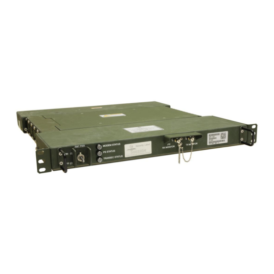
RUGGEDIZED IP MODEM
Brand:
L3 Communications
| Category:
Modem
| Size: 4 MB
Table of Contents
Table of Contents
3
List of Illustrations
7
List of Tables
11
Safety Precautions
13
How to Use this Manual
16
Technical Assistance, Reporting Errors and Recommending Improvements
18
Introduction
19
Overview
19
Provided Equipment
20
System Requirements
20
Software Version Information
21
Technical Specifications
22
Table 2-1 Technical Specifications
22
Controls and Indicators
23
Panel Indicators
23
Figure 3-1 Modem Panels
23
Table 3-1 Modem Panels
24
Software Installation
25
System Setup for Software Installation
25
Prepare PC for Software Installation
25
Figure 4-1 LAN Connection to PC
25
HCI Software Installation Procedure
26
Configure PC IP Address
26
Figure 4-2 IP Scheme
26
Human Computer Interface
27
Human Computer Interface Familiarization
28
Overall Status Screen
28
Figure 4-3 Select Mode
28
Figure 4-4 Overall Status Screen
28
Software Version Screen
29
Figure 4-5 Bottom Status Bar
29
Modem CDU Port IP Address
30
Figure 4-6 Software Menu
30
Figure 4-7 Configure Menu Tab
31
Figure 4-8 HCI to Modem Address Screen
31
Installation and Update Procedure - Modem
32
Figure 4-9 Configure Drop down Menu
32
Figure 4-10 Select Mode Screen
33
Figure 4-11 Software Menu
33
Figure 4-12 Software Download Showing Selected File
34
Figure 4-13 Open Screen to Select Software to Download
34
Figure 4-14 Software Downloading Status
35
Figure 4-15 Software Download Verification Screen
35
Figure 4-16 Software Rollover Start Screen
36
Figure 4-17 Software Rollover Successful Screen
36
Figure 4-18 Connection Lost Status Screen
36
Table 4-1 Software Download and Rollover Screen
36
Software Menu Overview
37
Launch Modem HCI
37
Figure 5-1 HCI Desktop Icon
37
Figure 5-2 Network Screen at Startup
37
SNMP Dialog
38
Figure 5-3 SNMP Mode Change
38
Figure 5-4 SNMP Configuration Dialog
38
Modes of Operation
39
Figure 5-5 Connection Lost Status Screen
39
Selecting Maintenance Mode
40
Figure 5-6 Select Mode
40
Figure 5-7 Configure Menu
40
System Shutdown
41
Figure 5-8 Select Mode Screen
41
Figure 5-9 Network Main Screen
41
File Pull-Down Menu
42
Figure 5-10 SCPC Main Screen
42
Figure 5-11 File Menu in Maintenance Mode
42
Save/Save as Configuration
43
Figure 5-12 Save Configuration
43
Table 5-1 File Configuration
43
Table 5-2 Save Configuration
43
Restore Configuration
44
Figure 5-13 Save as Dialog
44
Figure 5-14 Open Configuration Dialog
45
Figure 5-15 Restore Configuration
45
Figure 5-16 Confirm Restore Operation
46
Table 5-3 Restore Configuration
46
Configure Pull-Down Menu
47
Figure 5-17 Configure Menu
47
Table 5-4 Configure Menu
48
Monitor Pull-Down Menu
49
Figure 5-18 Monitor Menu
49
System Configuration
50
Configure System Screen
50
Figure 6-1 Configure Menu
50
Figure 6-2 System Configuration Screen
51
Configure Modem Screen
52
Figure 6-3 Modem Screen
52
Table 6-1 Configure System Configuration Screen
52
Satellite Setup
53
Satellite List Screen
53
Table 6-2 Modem Screen
53
Beams List
54
Figure 6-4 Satellite List Screen
54
Table 6-3 Satellite Database
54
Beam Edit Dialog
55
Figure 6-5 Beams List Screen
55
Figure 6-6 Edit Beam Dialog
55
Table 6-4 Beams List
55
Bandwidth Segments List
56
Figure 6-7 Bandwidth Segments
56
Table 6-5 Edit Beam Dialog
56
Bandwidth Segment Edit Dialog
57
Figure 6-8 Edit Bandwidth Segment Dialog Using Transfer Gain
57
Table 6-6 Bandwidth Segments
57
Figure 6-9 Edit Bandwidth Segment Dialog Using Saturated Flux Density
58
Table 6-7 Edit Bandwidth Segment
59
Multiple Modem Configuration
60
Configuring Master Modem
60
Figure 6-10 Modem Stack
60
Set the Mode of the Modem
61
Set the CDU and Data Ports
61
Figure 6-11 Configure File Menu
61
Figure 6-12 Select Mode Screen
61
Figure 6-13 Configure Drop down Menu
62
Configure Slave Modem
63
Figure 6-14 IP Address Configuration Screen
63
Figure 6-15 Change HCI to Modem Address
63
Figure 6-16 Configure Modem Screen
64
Figure 6-17 Configure Drop down Menu
65
Figure 6-18 Multi-Modem Configuration Screen
65
Figure 6-19 Configure Slave Modem
66
Figure 6-20 Multi-Modem Configuration
66
Figure 6-21 Configure Slave Modem
67
Figure 6-22 Slave Status after Changing Mode
67
Figure 6-23 Wait for Secure Link Status
68
Figure 6-24 Multi-Modem Status Screen
68
Table 6-8 Multi-Modem Status Screen
69
Terminal Calibration
70
File Entry Method
70
Figure 6-25 Figure Configure Menu
70
Figure 6-26 TERM CAL on Status Box
71
Figure 6-27 Terminal Calibration Screen
71
Figure 6-28 Calibration File Screen
72
Figure 6-29 File Validation Success
72
Figure 6-30 Losses Screen
73
Manual Entry Method
74
Figure 6-31 Terminal Losses File Screen
74
Figure 6-32 File Validation Successful
74
Figure 6-33 Configure Menu
74
Figure 6-34 Terminal Gains File Screen
75
Figure 6-35 Manual Entry Screen
76
Figure 6-36 Losses Screen
77
Nominal Value Method
78
Figure 6-37 Configure Menu
78
Figure 6-38 Nominal Entry
78
Figure 6-39 Losses Screen
79
Disable Terminal Calibration
80
Figure 6-40 Disable Terminal Calibration
80
Figure 6-41 Terminal Calibration off
80
Transmission Security
81
TRANSEC and MSK Initialization
81
Figure 7-1 Typical System Setup
81
Figure 7-2 TRANSEC Screen
82
Table 7-1 TRANSEC Screen
83
Figure 7-3 TRANSEC Screen
84
Figure 7-4 New Current MSK Entry Screen
84
Figure 7-5 MSK Entry Status Screen
85
Figure 7-6 TRANSEC Pass Phrase Selection Screen
85
Figure 7-7 Pass Phrase Entry Screen
86
Figure 7-8 Putty Security Alert Window
86
Figure 7-9 Status Screen for Secure Link
87
Network Control Operations
88
Network Overview
88
Network Controller and Network Members
88
Figure 8-1 Basic Network Architecture
88
Network Controller Capable
89
NCW Signals
90
Reference Forward Orderwire (RFOW)
90
Return Orderwire (ROW)
90
Data Communications Burst (DCOM)
91
NCW Traffic Example
91
Figure 8-2 MF-TDMA Structure
91
Network Initiation
92
Network Operation
92
Network Operation with Wideband Global Satellite
94
Setting the Terminal for NCW Mode as Network Controller
96
Figure 8-3 Configure Menu Tab
96
Figure 8-4 NCW Parameters Tab
97
NCW Network
98
NCW Network Tab
98
Figure 8-5 NCW Screen Network Tab
98
Table 8-1 NCW Network Tab
99
NCW Message Tab
100
Figure 8-6 NCW Message Tab
100
Table 8-2 NCW Message Tab
101
NCW Statistics Tab
102
Figure 8-7 NCW Statistics Tab
102
Table 8-3 NCW Statistics Tab
103
NCW BW/EIRP Tab
104
Figure 8-8 NCW BW/EIRP Tab
104
Table 8-4 NCW BW/EIRP Tab
105
NCW Path Loss Tab
106
Figure 8-9 NCW Path Loss Tab
106
Table 8-5 NCW Path Loss Tab
107
NCW RX Burst Tab
108
Figure 8-10 NCW RX Burst Tab
108
Table 8-6 NCW RX Burst Tab
109
NCW RX Comm Tab
110
Figure 8-11 NCW RX Comm Tab
110
Table 8-7 NCW RX Comm Tab
110
NCW TX Comm Tab
112
Figure 8-12 NCW TX Comm Tab
112
Table 8-8 NCW TX Comm Tab
112
NCW TX Queue Tab
113
Figure 8-13 NCW TX Queue Tab
113
Table 8-9 NCW TX Queue Tab
113
NCW Link Budget Tab
114
Figure 8-14 NCW Link Budget Tab
114
Table 8-10 NCW Link Budget Tab
114
NCW Setup Tabs
115
NCW Parameters Tab
115
Figure 8-15 NCW Setup Parameters Tab
115
Table 8-11 NCW Setup Parameters Tab
116
NCW Advanced Tab
117
Figure 8-16 NCW Setup Advanced Tab
117
Table 8-12 NCW Setup Advanced Tab
117
NCW QOS Tab
119
Figure 8-17 NCW QOS Tab
119
Table 8-13 NCW QOS Tab
119
Figure 8-18 Edit QOS Entry Dialog (QOS Tab)
120
NCW PSD Tab
121
Figure 8-19 NCW PSD Tab
121
Figure 8-20 Antenna Beamwidth Vs. Power Spectral Density
122
Table 8-14 NCW PSD Tab
122
Network Member Operations
123
Setting the Terminal for NCW Mode as a Network Member
123
Figure 9-1 Configure Menu Tab
123
NCW Network Member Tabs
124
NCW Network Tab
124
Figure 9-2 NCW Parameters Tab
124
Figure 9-3 NCW Network Tab
125
Table 9-1 NCW Network Tab
125
NCW Message Tab
127
Figure 9-4 NCW Message Tab
127
Table 9-2 NCW Message Tab
128
NCW Statistics Tab
129
Figure 9-5 NCW Statistics Tab
129
Table 9-3 NCW Statistics Tab
130
NCW RX Burst Tab
131
Figure 9-6 NCW RX Burst Tab
131
Table 9-4 NCW RX Burst Tab
132
NCW RX Comm Tab
133
Figure 9-7 NCW RX Comm Tab
133
Table 9-5 NCW RX Comm Tab
133
NCW TX Comm Tab
135
Figure 9-8 NCW TX Comm Tab
135
Table 9-6 NCW TX Comm Tab
135
NCW TX Queue Tab
136
Figure 9-9 NCW TX Queue Tab
136
Table 9-7 NCW TX Queue Tab
136
NCW Setup Tabs
137
NCW Parameters Tab
137
Figure 9-10 NCW Parameters Tab
137
Table 9-8 NCW Parameters Tab
138
NCW Advanced Tab
139
Figure 9-11 NCW Advanced Tab
139
Table 9-9 NCW Advanced Tab
139
NCW QOS Tab
140
Figure 9-12 NCW QOS Tab
140
Table 9-10 NCW QOS Tab
140
R2Cp Network Operations
141
R2CP Network Operations Tab
141
Figure 10-1 R2CP Config Tab
141
Table 10-1 R2CP Config Tab
142
R2CP Session Tab
144
Figure 10-2 R2CP Sessions Tab
144
Table 10-2 R2CP Sessions Tab
144
R2CP Operational State
145
Figure 10-3 R2CP Sessions Tab Operational State
145
Table 10-3 R2CP Sessions Tab Operational State
145
PIM Snooping and Multicast
146
Multicast Configurations
146
Figure 10-4 Multicast Config Tab
146
Table 10-4 Multicast Config Tab
147
Adding to the PIM Stateless Group List
148
Figure 10-5 Add to Multicast Group Dialog Box
148
Table 10-5 PIM Stateless Group
148
Group Status
149
Figure 10-6 Group Status Tab
149
Table 10-6 Group Status Tab
150
Scpc Network Operations
151
Selecting MIL-STD-188-165A (SCPC) Mode
151
Figure 11-1 Configure Menu
151
Figure 11-2 Select Mode Screen
151
Figure 11-3 MIL-STD-188-165A Configure Screen
152
Table 11-1 MIL-STD-188-165A Configure Parameters
153
Preventive Maintenance Checks and Services (Pmcs)
154
Introduction
154
Inspection
154
Cleaning
155
Description of PMCS Table Columns
155
Table 12-1 Operator Preventive Maintenance Checks and Services (PMCS)
156
Troubleshooting
157
Introduction
157
General Troubleshooting Guidelines
157
Modem BIT and Status Troubleshooting
157
Troubleshooting Tables
158
Alarms/Events
163
Setting Audible Alert for Alarms
163
Figure 13-1 Configure File Menu
163
Events Screen
164
Figure 13-2 Alarm Sound Audible Setting Screen
164
Active Alarms
165
Figure 13-3 Events Screen
165
Table 13-1 Events
165
Assistance
166
Figure 13-4 Antenna Active Alarm Screen
166
Maintenance
167
HCI Software Update
167
Figure 14-1 Remove Ipmodemhci
167
Modem Stacking Installation
168
Figure 14-2 Modem Stacking Interconnect Diagram
169
Maintenance Specifications
170
Panel Connector - Specifications
170
Figure 14-3 Panel Connections
170
Table 14-1 Rear Panel Connection Specifications Overview
171
External Signal Pin Assignments
172
Table 14-2 5 / 10 Mhz Frequency Standard Input Interface
172
Table 14-3 10 MHZ Frequency Standard Output Interace
172
Table 14-4 TX Intermediate Frequecy Output Interface
173
Table 14-5 TX Intermediate Frequecy Monitor Interface
173
Table 14-6 Modem RX Intermediate Frequency Input Interface
174
Table 14-7 RX Intermaediate Frequency Monitor Interface
174
Table 14-8 Control, Monitor and Alarm ETHERNET Interface
175
Table 14-9 Data ETHERNET Interface
175
Table 14-10 SCPC Baseband Interface
176
Table 14-11 Secure Voice Baseband Interface
177
Table 14-12 Terminal Devices Interface
178
Table 14-13 Power Input Interface
180
Table 14-14 Antenna Power Interface
180
Table 14-15 RS-485 SCPC Control Interface
181
Table 14-16 Maintenance Interface
181
Appendix A - Network Transmission Security
182
Keying Scheme
182
Figure 15-1 Overall Keying Scheme
182
Key Establishment
183
Access Control
183
Distribution
184
MSK Changeover
184
Changeover TRANSEC Passphrase Distribution
185
Passphrase Format
186
Recovery
186
Over-The-Air-Zeroize (OTAZ)
186
Recovery Protocol Actions at the Initiating Terminal
187
Recovery Protocol Actions at the Network Controller
187
Alternate Recovery Procedures
188
Key Usage
188
Network Initiation
189
TRANSEC Key Rollover
189
Appendix B - Rx Attenuator Description
190
Glossary of Abbreviations and Acronyms
191
Index
194
Advertisement
Advertisement
Related Products
L3 Communications MX-15i
L3 Communications Categories
Voice Recorder
Recording Equipment
Marine Radio
Modem
GPS
More L3 Communications Manuals
Login
Sign In
OR
Sign in with Facebook
Sign in with Google
Upload manual
Upload from disk
Upload from URL