Canon imageRUNNER ADVANCE C3330 Series Service Manual
Hide thumbs
Also See for imageRUNNER ADVANCE C3330 Series:
- Troubleshooting manual (200 pages) ,
- Service manual (952 pages) ,
- Service information (6 pages)
Table of Contents
Advertisement
Quick Links
Advertisement
Table of Contents
Troubleshooting

Related Manuals for Canon imageRUNNER ADVANCE C3330 Series


Summary of Contents for Canon imageRUNNER ADVANCE C3330 Series
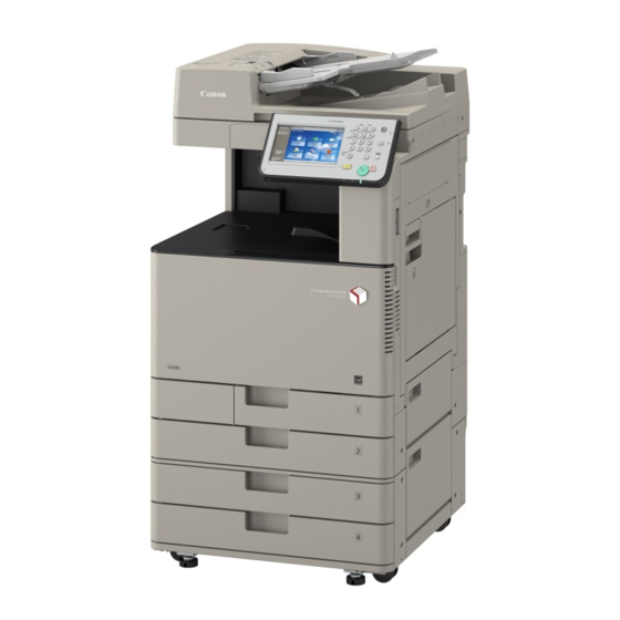
- Page 1 Revision 7.0 imageRUNNER ADVANCE C3330/C3325/C3320 Series Service Manual...
- Page 2 When changes occur in applicable products or in the contents of this manual, Canon will release technical information as the need arises. In the event of major changes in the contents of this manual over a long or short period, Canon will issue a new edition of this manual.
- Page 3 Introduction Symbols Explanation Symbols Explanation Disconnect the connector. Connect the power cable. Connect the connector. Disconnect the power cable. Remove the cable/wire from the Turn on the power. cable guide or wire saddle. Install the cable/wire to the cable Turn off the power. guide or wire saddle.
-
Page 4: Table Of Contents
Contents Contents Safety Precautions....................1 Laser Safety............................2 Handling of Laser System........................2 Turn power switch ON.........................2 Power Supply............................3 Toner Safety............................3 About Toner............................3 Handling Adhered Toner........................3 Notes When Handling a Lithium Battery..................... 3 Notes Before it Works Serving......................4 Points to Note at Cleaning........................4 Notes on Assembly/Disassembly...................... - Page 5 Contents Security Function (Encryption Key, Certificate and Protection of Password)..........43 HDD Encryption Kit (option)......................... 50 Laser Exposure System........................53 Overview............................53 Specification............................54 1-Polygon 4-Laser Method........................54 Controls..............................55 Image Formation System........................62 Overview............................62 Controls..............................64 Fixing System............................97 Overview............................97 Controls..............................99 Pickup / Feed System........................
- Page 6 Contents 4. Parts Replacement and Cleaning............... 246 Preface............................247 Outline..............................247 Points to Note when Tightening a Screw..................... 247 Parts Replacement / Cleaning Procedure List................248 List of Parts............................. 250 External Cover..........................250 Motor..............................254 Fan..............................255 Clutch...............................255 Solenoid............................256 Heater.............................. 256 Sensor..............................257 Switch..............................
- Page 7 Contents Removing the Primary Transfer Roller (Y/M/C/BK)................333 Removing the Patch Sensor Unit......................334 Removing the Waste Toner Drive Unit....................335 Removing the Registration Drive Unit / Duplex Merging Motor / Registration Motor........336 Removing the Main Drive Unit......................338 Removing the Drum Cleaning Pre-exposure LED Unit................. 341 Remove the Bottle Drive Unit (YM)/(CBk)....................343 Removing the Waste Toner Gear Holder.....................349 Removing the Waste Toner Feed Unit....................
- Page 8 Contents 6. Troubleshooting...................400 Initial Check.............................401 Initial check items list.........................401 Test Print............................402 Overview............................402 Steps to select the test print TYPE..................... 402 How to use the test print........................403 Troubleshooting Items........................407 Inaccurate Right Angle at the Paper Trailing Edge................407 Troubleshooting by Forcible Stop of Paper Feed................. 411 The ITB Unit Cannot Be Removed Due to a Disengagement Error of the Primary Transfer Roller...
- Page 9 Contents DADF-AQ1............................620 Inner Finisher-G1..........................621 Booklet Finisher-U1/Staple Finisher-U1/Buffer Pass Unit..............622 Alarm Code............................. 624 Alarm Code Details........................... 624 8. Service Mode....................644 Overview............................645 Entering Service Mode........................645 Service Mode Menu...........................645 Service mode item explanations......................645 I/O information enhancement......................646 Display of Error Code/Alarm Code description..................647 COPIER>...
- Page 10 Contents Checking the Contents........................1040 Check Items when Turning OFF the Main Power................1040 Installation Outline Drawing......................1040 Installation Procedure........................1041 Inner 2way Tray-J1........................1044 Points to Note at Installation......................1044 Checking the contents........................1044 Check Items when Turning OFF the Main Power................1044 Installation Outline Drawing......................1044 Installation procedure........................
- Page 11 Contents Installation Procedure ........................1094 Operation Check ..........................1106 Voice Guidance Kit-F2 / Voice Guidance Connection Kit for iR-ADV C3300 series..... 1111 Points to Note when Installing......................1111 Check Items when Turning OFF the Main Power................1111 Installation Outline Drawing......................1111 Checking the Contents........................1112 Installation Procedure........................
- Page 12 Contents Points to Note at Installation......................1167 Points to Note when Unpacking HDD Data Encryption & Mirroring Kit..........1167 Checking the Contents........................1168 Setting Before Turning OFF the Power..................... 1169 Check Items when Turning OFF the Main Power................1169 Installation Outline Drawing......................1170 Installation Procedure........................
-
Page 13: Safety Precautions
Safety Precautions Laser Safety.......... 2 Handling of Laser System..... 2 Turn power switch ON......2 Power Supply........3 Toner Safety..........3 Notes When Handling a Lithium Battery..........3 Notes Before it Works Serving....4 Points to Note at Cleaning....4 Notes on Assembly/Disassembly..4... -
Page 14: Laser Safety
Safety Precautions Laser Safety Since radiation emitted inside this machine is completely confined with protective housings, external covers and interlock switches, the laser beam cannot escape from the machine during any phase of normal use by users. Therefore, this machine is classified as a Class 1 laser product under the international standard IEC60825-1 that is regarded as safe during normal use. -
Page 15: Power Supply
Safety Precautions CAUTION: Do not turn off the main power switch while the progress bar is indicated, during which access is made to the HDD. If deprived of power, the HDD can suffer a fault (E602). Power Supply • As a general rule, do not use extension cords. If an extension cord must be used, however, use one for local rated voltage and over, untie the cord binding, and insert the power plug completely into the extension cord outlet to ensure a firm connection between the power cord and the extension cord. -
Page 16: Notes Before It Works Serving
Safety Precautions CAUTION: Risk of explosion if battery is replaced by an incorrect type. The following warnings are given to comply with Safety Principles (EN60950-1). CAUTION: Wenn mit dem falschen Typ ausgewechselt, besteht Explosionsgefahr. Gebrauchte Batterien gemäß der Anleitung beseitigen. Notes Before it Works Serving •... -
Page 17: Points To Note When Tightening A Screw
Safety Precautions CAUTION: Double pole/neutral fusing ACHTUNG Zweipolige bzw. Neutralleiter-Sicherung Points to Note when Tightening a Screw For reduction in weight, thin plates are used in some parts of this machine. In the case of a screw hole with a triangle mark near it as shown in the figure below, strongly tightening the screw may damage or deform the screw hole. -
Page 18: Product Overview
Product Overview Product Lineup........7 Features..........11 Specifications........17 Parts Name......... 26... -
Page 19: Product Lineup
1. Product Overview Product Lineup Positioning Color Lineup B/W Linup iR-ADV 6200 Series iR-ADV C7200 Series iR-ADV C5200 Series iR-ADV C2200 Series New Light iR-ADV 4200 Series iR-ADV 500/400 Series iR-ADV C350 Series Host machine < Product name > imageRUNNER ADVANCE C3330 / C3325 / C3320 Underlined (2-digit) numeric figures indicate print speed (ppm: print per minute). - Page 20 1. Product Overview Option ■ Pickup / Delivery / Image Reading System Options [17] [13] [12] [14] [10] [16] [11] [18] [15] Product name Condition [1][2] imageRUNNER ADVANCE C3330/C3325/C3320 DADF-AQ1 Cannot be installed with Platen Cover Type U. Platen Cover Type U Cannot be installed with DADF-AQ1.
- Page 21 1. Product Overview Product name Condition [19] Media Adjustment kit-A1 * For India region only ■ Function expansion system options [11] [14] [12] [13] [10] [15] Product name Condition Utility Tray-A2 Cannot be installed with Voice Operation Kit-C2. Copy Card Reader-F1 Copy Card Reader Attachment-B4 is required.
- Page 22 1. Product Overview Product name Condition Voice Guidance Connection Kit for iR-ADV C3300 series Voice Operation Kit-C2 Cannot be installed with Utility Tray-A2. HDD Data Encryption Kit-C9 [10] Document Scan Lock Kit-B1 [11] USB Device Port-E4 [12] Serial Interface Kit-K2 Cannot be installed with Copy Card Reader-F1.
-
Page 23: Features
1. Product Overview Features Product Features Improved usability Improved serviceability Improved serviceability ADF Pickup/ Separation Main Controller Toner Container Roller - Reduction in toner soiling - SITUATION MODE achieved by the new toner - Easier replacement deployed to office machines supply system Accessory Eco Staple... - Page 24 1. Product Overview ■ Improved Replaceability of Consumables ADF Pickup/ Drum Unit Separation Roller No tool required No tool required (no screws) (no screws) Waste Toner container Fixing Unit No tool required (no screws) Increased capacity Many of this machine's consumable parts can be replaced without tools. Furthermore, the following parts can be replaced by the user.
- Page 25 1. Product Overview ■ Item Numbers of Consumables Specified on Host Machine (reinforcement of the association between the host machine and the consumables) Control Panel UI Item numbers are assigned to user replaceable consumable parts separately from part numbers, and can be viewed in Status Monitor/Cancel >...
- Page 26 1. Product Overview Package Describing the same item number also on the part's package enhances the association between the part and the host machine at the user site. GENUINE ■ Maintenance Video for Consumables Replacement Videos are adopted to guide users with an easy-to-understand navigation of the replacement so that they can replace parts correctly without performing any wrong operation.
- Page 27 1. Product Overview *2: Can be set in COPIER > OPTION > FNC-SW > D-DLV-CL/BK ■ Setup Guide Setup Guide is designed to improve the workability during the installation by enabling to implement the series of necessary setting items at installation of a device in the format of a navigation. The items that can be set are as follows: Display Setting screen...
- Page 28 1. Product Overview Mode name Content Troubleshooting Items related to troubleshooting Parts Replacement Items performed at parts replacement Major Adjustment Major items of adjustment ■ Limiting of Color Printing Even if an error attributed to the Developing Unit or drum of any of the Y/M/C colors has occurred, B&W printing and copying remain possible without entering the limited printer function mode where the entire printing function stops.
-
Page 29: Specifications
1. Product Overview Specifications Specifications Item Specification/Function Copyboard Original fixed reading Machine installation Desktop method Light source White LED Photosensitive medi- Image reading sensor CMOS Exposure method Laser exposure Charging method DC Roller charging Developing method Dry, 2-component development + ACR method (ACR: Auto Carrier Refresh) Transfer method Intermediate Belt transfer Separation method... -
Page 30: Weight And Size
1. Product Overview Item Specification/Function Paper type Cassette : Thin (52 to 63 g/m ), Plain 1 (64 to 75 g/m ), Plain 2 (76 to 90 g/m ), Plain 3 (91 to 105 g/m ), Recycled 1 (64 to 75 g/m ), Recycled 2 (76 to 90 g/m ), Recycled 3 (91 to 105 g/m ), Color, Pre-Punched, Bond, Heavy 1... -
Page 31: Productivity
1. Product Overview Productivity Product name Productivity imageRUNNER ADVANCE C3330 Series 15 sheets / minute 15 sheets/minute 30 sheets/minute 30 sheets/minute 12" x 18" 7 sheets/minute 11" x 17" 15 sheets/minute 15 sheets/minute 30 sheets/minute EXEC 20 sheets/minute imageRUNNER ADVANCE C3325 Series... -
Page 32: Pickup
1. Product Overview Type Feeding direction (mm) Width direction (mm) Custom paper size 6-1 210 to 215.9 279.4 to 297 Custom paper size 6-2 216 to 279.3 Custom paper size 6-3 279.4 to 431.8 Custom paper size 7-2 139.7 to 147.9 297.1 to 320 Custom paper size 7-3 148 to 181.9... - Page 33 1. Product Overview Paper Type Size Feeding di- Width di- Pickup position rection rection Multi CST1 CST2 CST3 CST4 (mm) (mm) Thin paper (52 to 63 g/m Custom paper size 0-2, 0-3, 0-4, 1-1, 1-2, 1-3, Plain paper 1 (64 to 75 g/m 2-1, 2-2, 2-3, 2-4, 7-2, Plain paper 2 (76 to 90 g/m 7-3, 7-6, 8-1, 9...
- Page 34 1. Product Overview Paper Type Size Feeding di- Width di- Pickup position rection rection Multi CST1 CST2 CST3 CST4 (mm) (mm) Heavy paper 1 (106 to 128 g/ Custom paper size 3-2, 3-3, 5-3, 5-4, 5-6, 6-2, Heavy paper 2 (129 to 163 g/ 6-3, 7-4, 7-5 Heavy paper 3 (164 to 220 g/ Heavy paper 4 (221 to 256 g/...
- Page 35 1. Product Overview Paper Type Size Feeding di- Width di- Pickup position rection rection Multi CST1 CST2 CST3 CST4 (mm) (mm) 1-Side Coated Paper 1 (106 Custom paper size 0-2, to 128 g/m 0-3, 0-4, 1-1, 1-2, 1-3, 1-Side Coated Paper 2 (129 2-1, 2-2, 2-3, 2-4, 3-1, 3-2, 3-3, 5-1, 5-2, 5-3, to 163 g/m...
- Page 36 1. Product Overview Paper Type Size Feeding di- Width di- Pickup position rection rection Multi CST1 CST2 CST3 CST4 (mm) (mm) Labels (118 to 185 g/m SRA3 12x18 457.2 304.8 EXEC 184.1 266.7 Free Size 139.7 to 630 98.4 to 320 Custom paper size 0-2, 0-3, 0-4, 1-1, 1-2, 1-3, 2-1, 2-2, 2-3, 2-4, 3-1,...
- Page 37 1. Product Overview Paper Type Size Feeding di- Width di- Pickup position rection rection Multi CST1 CST2 CST3 CST4 (mm) (mm) Pre-Punched paper (64 to 75 I-LGL Free Size 139.7 to 630 98.4 to 320 Custom paper size 0-2, 0-3, 0-4, 1-1, 1-2, 1-3, 2-1, 2-2, 2-3, 2-4, 7-2, 7-3, 7-6, 8-1 Custom paper size 3-1,...
-
Page 38: Parts Name
1. Product Overview Parts Name Cross Sectional View Fixing Assembly Toner Container Secondary transfer ITB Unit outer Roller Drum Unit Laser Scanner Multi-purpose Tray Unit Waste Toner Container Cassette 1 Cassette 2 Cassette 3 Cassette 4 Control Panel Touch Panel Display Energy Saver key Numeric key Brightness... -
Page 39: Technology
Technology Basic Configuration......28 Document Exposure......29 Main Controller........38 Laser Exposure System...... 53 Image Formation System....62 Fixing System........97 Pickup / Feed System....... 111 External Auxiliary System....134 MEAP..........143 Embedded RDS........ 185 Updater..........198 DCM..........216... -
Page 40: Basic Configuration
2. Technology Basic Configuration Functional Configuration This machine consists of 6 major blocks: Original Exposure and Feed System, Controller System, Laser Exposure System, Image Formation System, Fixing System, and Pickup Feed System. Original Exposure and Feed System Reader Delivery Fixing Fixing System Controller System... -
Page 41: Document Exposure
2. Technology Document Exposure Overview ■ Characteristics This machine has achieved low energy consumption by adopting a new Scanner Unit. ■ Specifications Item Specification/function Remarks Exposure system High-brightness white LED + reflection plate Original scan In BOOK mode Scan by movement of scanner unit In DADF mode Scan by original stream reading with scanner unit fixed Scanning resolution... - Page 42 2. Technology ■ External View [10] [11] Name Reader Left Cover Reader Left Retaining Cover Reader Hinge Lower Cover (Left) Reader PCB Cover Reader Glass Support Cover Reader Rear Cover Reader Hinge Lower Cover (Right) Glass Cleaning Sheet Storage Box Reader Front Cover (Small) Reader Right Retaining Cover Reader Front Cover...
- Page 43 2. Technology ■ Major Electrical Parts STM1 HTR01 PS_N2 PS_N1 PS_R2 PS_A1 PS_R1 Component part Symbol Function/specification Scanner motor STM1 2 phase pulse motor: pulse control Scanner unit HP sensor PS_A1 Scanner unit HP detection DADF open/closed sensor (Front) PS_N1 DADF open detection (DADF is detected at 5 degree) DADF open/closed sensor (Rear) PS_N2...
-
Page 44: Controls
2. Technology Lens LED (light source) Reflection Mirror Mirror No.4 Mirror No.3 Mirror No.2 Mirror No.1 Mirror No.5 Lens Line Sensor [Red (R) line] [Greeen (G) line] [Blue (B) line] [Black & white (B/W) line] LED lamp unit On LED lamp unit, the light is generated from the 1 LED lamp PCBs (LED chip: 40 pieces per PCB). Generated light is exposed to the original through the reflection plate. - Page 45 2. Technology Mode Resolution Reading Speed Book mode 300dpi 260 mm/s 600dpi 150 mm/s ADF mode 300dpi 300 mm/s 600dpi 150 mm/s ■ Image Processing ● Overview The functions of the PCB related to image processing are shown below: Main Controller PCB •...
- Page 46 2. Technology Related Error Codes • E302-0001 : White Shading error • E302-0002 : Black Shading error Related Alarm Codes • 02-0025 : Insufficient Scanner Unit LED light intensity alarm ● Dust detection / correction control Overview Dust detection / correction control executes the following processing in association with the shading correction to correct image density variation (white streaks) in areas of dust.
- Page 47 2. Technology 0.5 mm 0.5 mm Stream Read Glass Related Service Mode • DADF mode dust dtct level adj: ppr intvl (Lv1) COPIER > OPTION > IMG-RDR > DFDST-L1 • DADF mode dust dtct level adj: after job (Lv1) COPIER > OPTION > IMG-RDR > DFDST-L2 ●...
- Page 48 2. Technology Color displacement correction processing is performed based on the color displacement correction values stored in service mode when a job is started. Related service mode • Reader scan correction value COPIER > ADJUST > CCD > 100-RG COPIER > ADJUST > CCD > 100-GB ■...
- Page 49 2. Technology AB type Inch type Original size sensor (AB/AK) Original size sensor (INCH) Original detection STMTR position 1 Original detection position 1 Original detection position 2 Original detection Original detection position 3 position 2 LTRR STMT Original detection position 4 Original detection 279.4×431.8mm Original detection position 5...
-
Page 50: Main Controller
2. Technology Main Controller Overview ■ Configuration / Function Main Controller PCB USB I/F TPM PCB Flash PCB Item Function Main Controller PCB System Control/Memory Control/Printer Output Image Processing Control, Reader Image Input Processing, Card Reader Connection I/F, Fax Image Processing, USB Extension HUB Connection I/F Temporarily storage of image data: Capacity of 1 GB (for controller control) + 1 GB (for image processing) USB port... - Page 51 2. Technology ■ Main controller PCB HDD ADF Reader Voice Internal I/F J38 J36 External I/F DEVICE PORT Memory Image Data Analyzer PCB FLASH Laser USB(D) USB(H) J25 J20 Main power Low voltage CC-VI CARD DC Controller supply power supply Functions and specifications Functions and specifications USB I/F (Device)
-
Page 52: Startup Sequence
2. Technology Startup Sequence Power Supply Switch ON [ ] : Program storage location - Initializing process of hardware - Starting BIOS [Main Controller PCB] - Starting IPL (boot program) and OS system software [Flash PCB] - Starting application [Hard disk] Standby screen display NOTE: To achieve faster startup, the progress bar and the active PCB are not synchronized. -
Page 53: Controls
2. Technology Controls ■ Image Data Flow ● Copy To DC Controller Reader Print the Image Image Processing Processing Resolution Conversion Image rotation Extension Processing JPEG Conversion/Extension HDD Writing/ Reading Image Data Buffer (Memory) Main Controller PCB ● Print To DC Controller Network Print the Image Rendering... -
Page 54: Security
2. Technology ● Network(Advanced Box / Space Client) Network To DC Controller Print the Image Processing JPEG Decode Extension Processing Controller HDD Writing/ Reading Image Data Buffer (Memory) Main Controller PCB ● Fax SEND Reader Image Processing Resolution Conversion JBIG MMR/MH Image rotation Conversion Image Level Cell... -
Page 55: Security Function (Encryption Key, Certificate And Protection Of Password)
2. Technology ● Complete Deletion of Hard Disk Data When copying, sending, receiving and printing, the machine separates the job data to save in the management information area and the actual data area. When a job is completed, the management information is automatically deleted, but the actual data remains on the hard disk. - Page 56 2. Technology TPM Chip TPM Chip Root Key Since the TPM key is safely stored using the root key in TPM Key the TPM chip, high security is maintained. Memory area Memory area Password Password Data Storing Key Data Storing Key Public Key Pair for Public Key Pair for User Certificate...
- Page 57 2. Technology When the TPM settings are disabled, the security information consists of a shared key and the information of multiple passwords stored in the Flash memory. Unlike when the TPM settings are enabled, stored password information is initialized upon failure/ replacement of the Flash memory.
- Page 58 2. Technology 2. Restart the machine after clicking "Yes". This function is enabled after restart. ● Backup of TPM key Only a USB flash drive (supported file system: FAT32) can be used as a device to save the backup file of the TPM key. The data size of this file is several MB.
- Page 59 2. Technology 3. After clicking [Password], enter the password (4 to 12 digits). Then, re-enter the verification password. 4. Click [OK]. Backup of TPM key starts.
- Page 60 2. Technology 5. When the screen indicating the completion of backup is displayed, click [OK], and remove the USB flash drive. CAUTION: Causes of backup failure In the following cases, a message indicating that the backup has failed and its cause are displayed. Take appropriate measures.
- Page 61 2. Technology 5. When the screen indicating the completion of restoration is displayed, click [OK], remove the USB flash drive, and then turn OFF and then ON the Main Power Supply Switch. CAUTION: Causes of restoration failure In the following cases, a message indicating that the restoration has failed and its cause are displayed. Take appropriate measures.
-
Page 62: Hdd Encryption Kit (Option)
2. Technology 2. Executes "Initialize All Data/Settings" to configure the TPM Setting to "Off". 3. Restore or import the data backed up or exported in step 1. Related error code • E746-0031: TPM error • E746-0032: TPM error • E746-0033: TPM error •... - Page 63 2. Technology CAUTION: The system does not need to be reinstalled when installing the HDD Encryption Kit. Because the system is stored in the Flash PCB, it does not need to be deleted. ■ Hard Disk Encryption Function Temporary image data such as scanned images and PDL data is written to the hard disk of the host machine as needed. Information of images and user files remains as-is on the hard disk after printing or file deletion because only management information is deleted in the course of normal operations.
- Page 64 2. Technology Service task User Data Recovery Countermeasure Clearing of the Main Controller Deleted After MN-CON clear process is done As the authentication information is not (COPIER > FUNCTION > MN- cleared by the clearing of MN-CON, there is CON) no work to be done specific to the HDD En- cryption Kit.
-
Page 65: Laser Exposure System
2. Technology Laser Exposure System Overview The laser exposure system forms a static latent image on the Photosensitive Drum by laser exposure. The Laser Scanner Unit consists of the Laser Assembly and the Scanner Motor, and is controlled by the signal from the DC Controller. -
Page 66: Specification
2. Technology UN08 UN09 Name Imaging Lens Reflection Mirror Polygon Mirror BD signal light-receiving section UN08 C/Bk Laser Driver PCB UN09 Y/M Laser Driver PCB Scanner Motor Specification Item Description Wave length 780 to 800 nm Laser type Infrared (invisible) laser Laser output 10 mW Number of Laser Scanner Units... -
Page 67: Controls
2. Technology UN08 UN09 Name Reflection Mirror Imaging Lens Photosensitive Drum UN08 C/Bk Laser Driver PCB UN09 Y/M Laser Driver PCB Scanner Motor Controls ■ Overview Item Operation description Laser ON/OFF control Turns the laser beam ON and OFF according to the combina- “Laser ON/OFF control”... - Page 68 2. Technology Item Operation description APC(Auto Power Control) control Ensures constant laser beam light intensity for each line. “APC(Auto Power Control) control” on page 59 BD correction control Corrects displacement of BD timing for the displacement of the “BD correction control” on Polygon Mirror angle.
- Page 69 2. Technology Print Image formation instruction ready timing Printer PSTBY PINTR PRINT LSTR PSTBY status At 1st line (APC) LaserA Mode Standby Forcible Standby APC mode APC mode / Print mode name mode OFF mode mode ■ Horizontal scanning synchronous control Purpose Aligns the write start position in the horizontal scanning direction.
- Page 70 2. Technology Execution timing At each print Control description 1. When the DC Controller receives a print order, it detects an internal reference signal. Based on this signal, a vertical scanning synchronous signal (ITOP) is generated and sent to the Main Controller. 2.
- Page 71 2. Technology Control description Scanner Motor rotation speed is controlled by the Y/M Laser Driver PCB. 1. The Y/M Laser Driver PCB outputs Scanner Motor control signals (acceleration signal: ACC, deceleration signal: DEC) to the Scanner Motor to rotate the Polygon Mirror. 2.
- Page 72 2. Technology 2. The APC mode is set for the Y/M and C/Bk Laser Driver PCB ICs, and the laser diode of each color is forcibly emitted. The photo diode (PD) monitors the laser diode (LD), and each Laser Driver IC adjusts the output of laser diode until the laser light intensity reaches a specified level.
- Page 73 2. Technology • E110-0001: Scanner Motor error • E110-0002: Scanner Motor error • E110-0003: Scanner Motor error • E110-0004: Scanner Motor error...
-
Page 74: Image Formation System
2. Technology Image Formation System Overview ■ Specifications Item Function/Method Photosensitive Drum Material : OPC Drum diameter : 30 mm in diameter Cleaning : Cleaning Blade Process speed 1/1 speed: 119.4 mm/s 1/2 speed: 59.7 mm/s Drum Heater : None Developing Unit Developing Cylinder : 1 cylinder (single-developing method) Developing method : Dry, 2-component development + ACR method (ACR: Auto Carrier Refresh) - Page 75 2. Technology Name Toner Bottle Drum Unit Laser Scanner Unit ■ Print Process Delivery Flow of print paper Rotating direction of ITB, Fixing block photosensitive drum 7.Fixing ITB cleaning block Transfer block 6.Separation 8.ITB cleaning 5.Secondary transfer 4.Primary 4.Primary 4.Primary 4.Primary transfer transfer...
-
Page 76: Controls
2. Technology Bias name Bias Application location Control PCB types Secondary Transfer High Voltage PCB (UN03) Developing bias (DC) Developing Cylinder Developing bias (AC) Primary transfer bias Primary Transfer Roller Primary Transfer High Voltage PCB (UN02) Secondary transfer bias Secondary Transfer Outer Roller Secondary Transfer High Voltage PCB (UN03) The abovementioned biases are generated by the 2 High Voltage PCBs and are also supplied to the loads used in printing process. - Page 77 2. Technology Transfer/Separation “Transfer/Separation” on page 71 Separation “Separation” on page 77 Waste Toner Feed Unit “Waste Toner Feed Unit” on page 92 Parts / Drive Configuration “Parts / Drive Configuration” on page 92 Waste Toner Container Full Level Detection “Waste Toner Container Full Level Detection”...
- Page 78 2. Technology Parts name Role CL01 Developing Cylinder Clutch (Y) Switching of the drive path to the Developing Unit (Y) CL02 Developing Cylinder Clutch (M) Switching of the drive path to the Developing Unit (M) CL03 Developing Cylinder Clutch (C) Switching of the drive path to the Developing Unit (C) CL04 Developing Cylinder Clutch (Bk)
- Page 79 2. Technology • Setting of the activation conditions of the Cleaning Pre-exposure LED: COPIER > OPTION > FNC-SW > PREXP-SW • Adjustment of the Cleaning Pre-exposure LED (Y) light intensity (1/1 speed): COPIER > ADJUST > EXP-LED > PR-EXP-Y • Adjustment of the Cleaning Pre-exposure LED (M) light intensity (1/1 speed): COPIER >...
- Page 80 2. Technology Operation of the host machine When the Drum Unit is detected as absent, the message "Cannot recognize the drum." is displayed on the LUI status line. NOTE: Detection of presence/absence of a Drum Unit may not be executed at times such as at recovery from sleep mode (of less than 8 hours).
- Page 81 2. Technology 2. The value calculated in step 1) is added to the Drum count value that has been stored in the IC tag of the Drum Unit. DC Controller PCB (UN04) Life Information Drum Unit Memory PCB (UN35〜38) Drum Unit Memory NOTE: The life (displayed in %) can be checked by the following service mode: COPIER >...
- Page 82 2. Technology ● Primary Charging Primary charging bias control Purpose To apply voltage to the Primary Charging Roller in order to charge the Photosensitive Drum Surface to a negative potential Charging method Roller charging (DC charging (no AC charging)) The primary charging bias (DC negative), which has been generated by the Secondary Transfer High Voltage PCB (UN03), is applied to the Primary Charging Roller.
- Page 83 2. Technology Developing bias control Purpose To apply voltage to the Developing Cylinder in order to generate a potential difference from the Photosensitive Drum Control description The developing bias (AC, DC negative), which has been generated on the Secondary Charging PCB (UN03), is applied to the Developing Cylinder.
- Page 84 2. Technology Related error code E010: Bk Drum_ITB Motor error • E010-0001: BK Drum Motor startup error • E010-0002: BK Drum Motor speed error • E010-0003: BK Drum Motor lock detection ● Primary Transfer Control Primary Transfer ATVC Purpose The transfer voltage required to obtain the target transfer current value is set in order to prevent transfer failure due to environmental changes.
- Page 85 2. Technology NOTE: The ATVC control secures transfer performance that is not affected by change in resistance caused by the environment as well as deterioration of the Primary Transfer Roller and is executed respectively to the primary transfer bias of each color. ●...
- Page 86 2. Technology Color Primary transfer disengagement initialization operation Initialization is performed so that the coupling is securely engaged at power-on and when the door is closed because the state of the primary transfer disengagement is not determined. Operation description The Primary Transfer Disengagement Cam [1] is rotated so that the mode shifts in the following order: Bk mode, Color mode, and Full disengagement mode.
- Page 87 2. Technology Mode Status Operation status Full disengage- ment mode *1: When image formation is executed *2: Disengagement is not performed during the operation for entering the deep sleep mode. ● ITB Displacement Correction Purpose To prevent problems caused by ITB displacement. Control description With this machine, belt displacement is prevented by ITB displacement correction using a rib guide mechanism.
- Page 88 2. Technology Parts name Role ITB Cleaning Screw Residual toner in the ITB Cleaning Unit is fed. ITB Cleaning Blade Residual toner on the ITB is collected. Waste Toner Ejection Mouth Ejection Mouth for toner collected on the ITB Bk Drum _ ITB Motor The ITB Cleaning Screw is driven.
- Page 89 2. Technology Control timing Adjustment timing Condition At startup When turning ON the main 8 hours or more have elapsed in high-speed startup mode power At normal startup At recovery from sleep mode 8 hours or more have elapsed in sleep mode Automatic adjustment by replace- When replacing the Drum When a new Drum Unit is inserted...
- Page 90 2. Technology Related Alarm Code • 10-0006 : Patch Sensor error 1 • 10-0007 : Patch Sensor error 2 ● Control Timing List Execution items for image stabilization control differ according to the environment and condition of image formation parts. Following shows the control items at each sequence.
- Page 91 2. Technology Control Conditions for exe- Type of control timing cution Laser power D-half con- ARCDAT Color dis- Patch Sen- PASCAL correction trol control placement sor adjust- control control correction ment control At job com- At last rotation for each pletion accumulated 1000 im- ages...
- Page 92 2. Technology 3. The DC Controller PCB measures the patch pattern using the Registration Patch Sensor Unit (Rear/Front) (UN25/26) and the result is returned to the Main Controller PCB. 4. The Main Controller PCB compares this measured data with the reference data for ARCDAT control that has been backed up.
- Page 93 2. Technology Correction description Type of control Correction description Correction in horizontal scanning direc- Write start correction Write-start timing in horizontal scanning tion direction is changed. Overall magnification ratio correction Pixels in horizontal scanning direction is increased/reduced (at the both edges of the image) Correction in vertical scanning direction Write start correction Write-start timing in vertical scanning di-...
- Page 94 2. Technology Patch Sensor Light-receiving element Light-emitting element Patch image P-wave : S-wave : Light intensity adjustment The light intensity of the Patch Sensor is changed sequentially and adjusted such that the P wave output is 2.5 V. Sampling of the ITB background To prevent uneven reflection in the inner circumference of the ITB, the background of the whole circumference of the ITB is sampled by the Patch Sensor without forming patches.
- Page 95 2. Technology 4. The Main Controller PCB creates an image gradation density correction table from the gradation density data of patch pattern scanned by the Reader. Reader Patch image data Printer PASCAL control Related service mode • Setting of auto gradation adjustment target selection screen: COPIER >...
- Page 96 2. Technology ● Opening/Closing of Toner Container Shutter Purpose The Toner Container Shutter is opened/closed to prevent toner from scattering. Toner Head Assembly Toner Container Claw Lever Shutter ● Bottle State Detection Purpose Check whether there is a problem with the inserted Toner Container. Detection timing •...
- Page 97 2. Technology Screen Display A message shown below is displayed according to the condition detected from the memory. Message State Cartridge with wrong item no. may be in- A Toner Container with a wrong item number is inserted. serted. Toner cartridge may be malfunctioning. A Toner Container that may be malfunctioning is inserted.
- Page 98 2. Technology ● ATR (Auto Toner Replenishment) Control Purpose To supply toner to the Developing Unit to achieve an ideal ratio of the developer (toner + carrier) in the Developing Unit. Execution timing Control timing Adjustment timing Condition Automatic adjustment by the accu- At job completion For each accumulated video count value of mulation of video count values...
- Page 99 2. Technology • E020-04C8: Error in take-up of Sealing Member (Bk) ● Toner Supply Control Purpose Toner is supplied from the Toner Container to the Developing Unit. Control description This machine uses a Toner Container that has an accordion mechanism at the end. The drive of the Bottle Motor rotates the Toner Bottle and operates the accordion section.
- Page 100 2. Technology 2. The driving force is transmitted to the gears, and the Toner Bottle rotates. REAR VIEW 3. When the motor rotates in the reverse direction, the Idler Gear moves to the opposite direction. 4. The driving force is transmitted only to the gears on the side toward which the gear moved, and the Toner Bottle rotates and toner is supplied.
- Page 101 2. Technology to drop to the cut-off part of the Toner Bottle as shown in the figure below, which in turn switches OFF the sensor. After that, when the flag of the Toner Supply Sensor moves out of the cut-off part, the sensor is turned ON. When the Toner Supply Sensor is OFF, 1 block's worth of toner is supplied to the Developing Unit.
- Page 102 2. Technology Prior delivery alarm Empty toner Display Remaining Toner error Detected to (location) Toner Density Sensor Toner supply count Message None Toner is low. Replacement not yet nee- Replace the toner cartridge. (Operation of the host ded. (Host machine is stopped.) machine) (Continuous printing is enabled.) Alarm Code...
- Page 103 2. Technology NOTE: The toner container premature replacement detection function utilizes the Bottle New/Old Sensor, and does not work for unidentified Toner Containers. Control description Display a message when the Toner Container Suspend operation when the Toner Contain- Complete is removed er is prematurely replaced the toner re- placement...
- Page 104 2. Technology • ON/OFF of display of the message at removal of the Toner Container (Lv. 2) COPIER > OPTION > USER > TNRBEXGR Related alarm codes 10-0100-0071: Number of installations of new Toner Containers (Bk) 10-0100-0072: Number of installations of new Toner Containers (Y) 10-0100-0073: Number of installations of new Toner Containers (M) 10-0100-0074: Number of installations of new Toner Containers (C) 10-0100-0181: Number of installations of unidentified Toner Bottles (Bk)
- Page 105 2. Technology Parts name Role SW01 Waste Toner Container Detection Waste Toner Container detection Switch ● Waste Toner Container Full Level Detection Purpose Toner level accumulated in the Waste Toner Container is detected. Registration Motor UN30 Waste Toner Sensor [ Waste Toner Container [ Toner low : SensorON ] preparation warning : Sensor OFF ]...
- Page 106 2. Technology The parts counter is automatically cleared, but it is not cleared if the Waste Toner Container is replaced while "preparation warning" or "full" is not detected or while the power is off. The parts counter can be manually cleared by executing the following service mode. COPIER >...
- Page 107 2. Technology • Setting of the image ratio for executing the C-color toner ejection (Lv.2): COPIER > OPTION > IMG-DEV > DELV-THC • Setting of the image ratio for executing the Bk-color toner ejection (Lv.2): COPIER > OPTION > IMG-DEV > DELV-THK •...
- Page 108 2. Technology ● Behavior when color printing is limited or there is no color toner Purpose To enable B&W printing and copying without stopping the entire printing function when an error attributed to the Y/M/C Developing Unit or when there is no Y/M/C toner. When color printing is limited or there is no color toner, the following Settings/Registration menu cannot be executed: •...
-
Page 109: Fixing System
2. Technology Fixing System Overview In the fixing system, toner that has been transferred to the paper by process in the image formation system is fixed. This machine uses the on-demand fixing method for fixing. PS10 Name Fixing Pressure Roller Fixing Film Sensor Flag Fixing Heater... - Page 110 2. Technology ■ Major Components UN31 PS10 TH01_01 TH01_02 TP01 TH01_03 Parts name Function/Method Fixing Pressure Roller A toner image on paper is fixed by applying heat and pressure. Fixing Film Unit Fixing heater For heating the center/edges of the Fixing Film (Ceramic Heater) TH01_02 Main Thermistor This is engaged with Heater.
-
Page 111: Controls
2. Technology Controls ■ Overview of Fixing Temperature Control Fixing temperature STBY INTR PRNT Startup Sheet-t During-print (warm-up o-sheet Flying start control rotation) control control temperature control temperature temperature temperature Time Command for Command for flying start print start ● Standby Temperature Control This is a control to pre-heat the Fixing Assembly to reduce time to start printing. - Page 112 2. Technology ● Flying Start Purpose To reduce time to print the first sheet (FCOT). Startup conditions • When Control Panel Numeric Keypad/Touch Panel is pressed • When the Main Power Switch is turned ON* • When recovering from sleep mode to standby mode* •...
- Page 113 2. Technology Paper type Resolution Fixing speed Target temperature (deg C) Paper weight (g/m (dpi) (mm/s) Color 119.4 Recycled paper 1 64 to 75 169 to 207 169 to 207 Recycled paper 2 76 to 90 175 to 209 169 to 203 Recycled paper 3 91 to 105 195 to 230...
- Page 114 2. Technology Paper type Paper weight Paper Width (mm) Resolution Fixing speed Target temperature (deg C) (dpi) (mm/s) (g/m Color 1-Sided Coated 3 164 to 220 600 / 1200 59.7 305.1 + 184 to 212 2-Sided Coated 3 Label paper Heavy paper 4 221 to 256 300.1 +...
- Page 115 2. Technology • Paper width 300.1 mm to 320 mm: Plain paper, Recycled paper, Thin paper, Color paper, Tracing paper, Pre-punched paper, Bond paper : COPIER > OPTION > IMG-FIX > TMP-TB20 • Paper width 300.1mm to 305 mm: Heavy paper, Coated paper, Label paper : COPIER >...
- Page 116 2. Technology Paper type Paper weight Resolution Fixing speed Target temperature (deg C) Print speed (dpi) (mm/s) (ppm) (g/m Color 119.4 15 to 4 Tracing paper 64 to 99 180 to 214 173 to 209 Pre-punched paper 64 to 75 Thin paper 52 to 63 1200...
- Page 117 2. Technology Paper type Paper weight Paper Resolution Fixing speed Target temperature (deg C) Print speed Width (dpi) (mm/s) (ppm) (g/m Color (mm) 600 / 1200 59.7 8 to 2 Heavy paper 4 221 to 256 300.1 + 183 to 213 305.1 + 192 to 220 Related Service Mode...
- Page 118 2. Technology Engaged state Disengaged state PS13 PS13 Sensor flag is ON Sensor flag is OFF Name Pressure Release Gear Cam Gear Fixing Film Fixing Pressure Roller PS13 Fixing Pressure Release Sensor Execution condition/timing Engagement operation • At power-on(*) • At recovery from sleep mode(*) •...
- Page 119 2. Technology To prevent these symptoms, one Arch Sensor (PS11) located at the inlet of the Fixing Unit detects the slack of paper and adjusts the the rotation speed of the Fixing Motor. This keeps an appropriate level of paper slack. The Arch Sensor (PS11) detects a paper arch between the transfer nip and fixing nip, and changes the drive speed of the Fixing Motor as follows: 1.
- Page 120 2. Technology ■ Fixing Unit Life Detection Purpose To detect the life of the Fixing Unit in order to prevent fixing errors due to the Fixing Unit having reached the end of life This machine has a counter in the DC Controller to determine the life of the Fixing Unit. The life of the Fixing Unit is determined by the following 3 conditions: 1.
- Page 121 2. Technology Fixing Assembly UN04 Fuse detection signal Fuse cut signal UN31 Related Error Code • E811-0000: Fuse in the Fixing Fuse PCB blowout error ■ Protection function This machine has the following error codes to protect the Fixing Unit. Error Codes Detail Code Description...
- Page 122 2. Technology Error Error Detection First time Second and later times E002 Displayed as 0CF1 JAM Displayed as E002 error E003 Displayed as E003 error In either case, the error does not need to be cleared in service mode as replacing the Fixing Unit with a new one blows the fuse of the Fixing Fuse PCB and at the same time clears the error.
-
Page 123: Pickup / Feed System
2. Technology Pickup / Feed System Overview ■ Characteristics Support for envelopes Envelope can be fed from the cassette of the machine. Improved Multi-purpose Tray usability The usability has been improved by automatic paper size recognition for Multi-purpose Tray pickup. ■... - Page 124 2. Technology ■ Parts Configuration ● Layout Drawing of Rollers [21] [10] [12] [11] [22] [13] [14] [15] [20] [16] [17] [19] [18] Name Name Second Delivery/Reverse Roller Multi-purpose Tray Feed Roller Third Delivery Roller Cassette 1 Vertical Path Roller Reverse Vertical Path Roller 1 Cassette 1 Feed Roller Duplex Roller 1...
- Page 125 2. Technology ● Layout Drawing of Sensors [PS53] [PS52] [PS51] [PS12] [PS14] [PS10] [PS22] [PS08] [PS24] Name Name PS08 Cassette 1 Vertical Path Sensor PS24 Cassette 2 Vertical Path Sensor PS10 Fixing Outlet Sensor PS51 Second delivery / Reverse sensor PS12 Reverse Sensor PS52...
- Page 126 2. Technology ● Diagram of load drives When the 3-Way Unit is connected SL06 Name Name Cassette 1,2 Pickup Motor Cassette 1,2 Feed / Multi-purpose Pickup Motor Fixing Motor Duplex Merging Motor Duplex Reverse Motor Reverce Motor Registration Motor Second Delivery Motor SL06 Duplex Reverse Solenoid...
- Page 127 2. Technology Without 3-Way Unit SL06 Name Name Cassette 1,2 Pickup Motor SL06 Duplex Reverse Solenoid Fixing Motor Duplex Reverse Motor Registration Motor Cassette 1,2 Feed / Multi-purpose Pickup Motor Duplex Merging Motor...
- Page 128 2. Technology ■ Paper Path When the 3 Way Unit-D1 is connected Acceleration section Reverse Mouth Third Delivery Second Delivery Reverse Mouth First Delivery Multi-purpose Tray Pickup Cassette 1 Pickup Cassette 2 Pickup...
- Page 129 2. Technology When the 3 Way Unit-D1 is not connected Acceleration section Reverse Mouth First Delivery Multi-purpose Tray Pickup Cassette 1 Pickup Cassette 2 Pickup...
-
Page 130: Controls
2. Technology Controls ■ Overview Reverse /Duplex Assembly Fixing/ Registration Assembly Multi-purpose Tray Pickup Assembly Cassette 1 Cassette 2 Area Detection, Control Cassette Pickup Assembly “Cassette Pickup Assembly” on “Lifter control” on page 120 • Cassette 1 page 119 “Cassette Pickup Control” on page 120 •... - Page 131 2. Technology ■ Cassette Pickup Assembly ● Parts Configuration PS04 PS08 PS05 PS18 PS17 SW13 PS06 PS20 PS07 PS24 PS19 SW16 SW15 Name Cassette 1 Vertical Path Roller Cassette 1 Feed Roller Cassette 1 Separation Roller Cassette 1 Pickup Roller Cassette 2 Separation Roller Cassette 2 Feed Roller Cassette 2 Pickup Roller...
- Page 132 2. Technology ● Drive Configuration Name Cassette 1 Pickup Roller Cassette 1 Vertical Path Roller Cassette 1 Feed Roller Cassette 1 Separation Roller Cassette 2 Vertical Path Roller Cassette 2 Feed Roller Cassette 2 Separation Roller Cassette 2 Pickup Roller Lifting Plate Cassette 1,2 Lifter Motor Cassette 1,2 Pickup Motor...
- Page 133 2. Technology • 04-0014: Cassette 4 Pickup Retry Error ● Cassette Paper Size Detection/Cassette Detection Result of automatic Paper Size Group for Auto Recognition in Drawer*1 size detection All sizes A/B size Inch size A/K Size No corresponding size No corresponding size No corresponding size No corresponding size No corresponding size...
- Page 134 2. Technology SW13 Name Trailing Edge Guide Plate Side Guide Plate SW13 Cassette 1 Size Switch Cassette 2 The paper size in the cassette is automatically detected by the Cassette 2 Size Switch A/B after the position of the Guide Plate is adjusted.
- Page 135 2. Technology SW15 SW16 Name Trailing Edge Guide Plate Link Arm Side Guide Plate Size Detection Plate SW15 Cassette 2 Size Switch A SW16 Cassette 2 Size Switch B Related Setting/Registration • Selection between A5-R and STMT-R in a cassette [Settings/Registration] >...
- Page 136 2. Technology • Cassette Lifter Sensor The paper level is displayed in four levels in the Control Panel. Level display Level display Level Paper Level Sen- Paper Level Sen- Paper Sensor Cassette Lifter sor A sor B Sensor 100 to 50% 50 to 10% 10 to 0% PS05...
- Page 137 2. Technology Cassette 1 PS04 PS05 PS18 PS17 Name Lifter Gear Paper Detection Lever Middle Plate PS04 Cassette 1 Lifter Sensor PS05 Cassette 1 Paper Sensor PS17 Cassette 1 Paper Level Sensor A PS18 Cassette 1 Paper Level Sensor B Cassette 2 PS06 PS07...
- Page 138 2. Technology Name PS20 Cassette 2 Paper Level Sensor B ■ Multi-purpose Tray Pickup Assembly ● Parts / Drive Configuration PS31 PS30 UN29 PS32 PS03 Name Multi-purpose Tray Pickup Roller Multi-purpose Tray Feed Roller Multi-purpose Tray Separation Roller PS03 Multi-purpose Tray Paper Sensor PS30 Multi-purpose Tray Paper Length Sensor 1 PS31...
- Page 139 2. Technology ● Multi-purpose Tray paper detection Presence/absence of paper on the Multi-purpose Tray is detected by the Multi-purpose Tray Paper Sensor (PS03). ● Multi-purpose Tray Automatic Size Detection The paper size shown below to which automatic size detection is performed is determined according to the setting of "Settings/ Registration >...
- Page 140 2. Technology 2. Configure the long original mode in the following mode after changing the service mode setting. Copy > Other Functions > Long Original When setting Long Original, paper cannot be delivered to the Third Delivery Outlet. ■ Fixing/Registration Assembly ●...
- Page 141 2. Technology PS22 PS22 Name Paper Registration Roller Slack Duplex Merging Roller PS22 Pre-Registration Sensor Registration Motor Duplex Merging Motor The feed control to align the leading edge of paper with the leading edge of image uses the Pre-Registration Sensor as the reference for detecting the leading edge, and "non-stop registration control"...
- Page 142 2. Technology ■ Reverse / Delivery Assembly ● Parts / Drive Configuration When the 3 Way Unit-D1 is connected SL06 Name Name Second Delivery/Reverse Roller Fixing Motor Reverse Vertical Path Roller 1 Duplex Reverse Motor Reverse Vertical Path Roller 2 Reverse Motor First Delivery Roller Second Delivery Motor...
- Page 143 2. Technology ● The Number of Circulating Sheets, Feed Path and Reverse/Standby Control at 1- sided/2-sided Feeding With this machine, the number of circulating sheets, feed route, reverse position and standby position (1- and 2-sided) differ according to the set length of fixed size paper and delivery outlet. Standby timing at standby position (1- and 2-sided) •...
- Page 144 2. Technology When the 3 Way Unit-D1 is installed Standard size Paper length Delivery Number of Feed path Reverse po- Standby position circulating sition sheets STMT, A5 92 to 181.9 mm First deliv- Duplex not supported Second de- livery Third deliv- B5 to LTR or smaller 182 to 216 mm First deliv-...
- Page 145 2. Technology Code* Symbol Sensor name Jam Type (xx)* IO > DCON 1 = Paper present xx08 PS51 Second Delivery / Reverse Sensor P006 > bit 2 > 1: Paper present xx09 PS52 Third Delivery Sensor P006 > bit 1 > 1: Paper present xx0A PS12...
-
Page 146: External Auxiliary System
2. Technology External Auxiliary System Controls ■ Software Counter Control This machine has software counters which count the number of prints/copies according to the job type. Various counters are displayed by pressing the Check Counter key on the Control Panel. The default counters for each country (model) are listed below. - Page 147 2. Technology Target Number displayed for each counter (in service mode)/Item Target country Counter 1 Counter 2 Counter 3 Counter 4 Counter 5 Counter 6 Counter 7 / code type2 GER model Total (Black/ Total (Black/ Total Total Scan (Total Print (Total 1) type1 Large)
- Page 148 2. Technology • Print mode (1-sided print/2nd side of 2-sided print, 1st side of 2-sided print) • Delivery position (Finisher) Count-up timing list Delivery position Print mode 1-sided print/2nd side of 2-sided print 1st side of 2-sided print Host First Delivery When detected by the First Delivery Sensor (PS14) When detected by the Reverse Sensor Tray...
- Page 149 2. Technology Controlled by DCON MCON Fan Name Front Fan ( FM01 ) Motor Fan ( FM02 ) Power Supply Controller Fan Cooling Fan ( FM04 ) ( FM03 ) At printing 2-sided Full speed Half speed Full speed Full speed Reader operation Half speed /Stopped*2 Half speed /Stopped*2...
- Page 150 2. Technology ■ Power supply ● Internal power supply Main Power SW Low Voltage Power Supply PCB Main Controller PCB 3.3V 3.3V All-night All-night Power Supply Circuit AC/DC RCON Non-all-night Power Supply Power Supply Circuit AC/DC AC/DC Non-all-night Power Supply Circuit DC/DC 24V 5V...
- Page 151 2. Technology * The time specified in Settings/Registration> Preferences> Timer/Energy Settings> Auto Sleep Time Standby Mode The mode in which the machine is running or can start operation immediately and all power is supplied. When turning OFF the Control Panel Power Switch or the specified period of time has passed, the mode is shifted to Sleep mode. When turning ON the Control Panel Power Switch while in Sleep Standby mode, the mode is shifted to this mode.
- Page 152 2. Technology • During export/import by Remote UI • MEAP application is being executed (depending on the MEAP application) • During backup of Mail Box documents • A file is being opened (read/written) in Settings/Registration > Access Stored Files > Network. (*Common with WebDAV and SMB) •...
- Page 153 2. Technology The following label is used at the place where attention is required. Quick Start Plug Off In addition, quick startup is not performed under the following conditions. Conditions for not executing quick startup This machine does not execute quick startup if the following conditions are met at first startup after the power plug is connected to the outlet.
- Page 154 2. Technology When entering and exiting Deep Sleep, this machine is electrically disconnected from the network. Therefore, when connected to a hub with the spanning tree feature, communication with the network is disabled for up to about one minute after exiting from Deep Sleep.
-
Page 155: Meap
2. Technology MEAP Function Overview ■ Overview of System MEAP (Multifunctional Embedded Application Platform) is an application platform (execution platform) that allows the user to execute an application written in the Java language on a Java virtual machine installed on the device. In this chapter, a device with MEAP is called a device supporting MEAP, and an application which runs on MEAP is called a MEAP application. - Page 156 User Attribute: memberOf Not Available Available Character String: Canon Peripheral Admins Available Available The settings of the administrator can be changed on the following screen: remote UI > Settings/Registration > Management Settings > Authentication Management > Preferences (http://device's IP address:8000/userauth/Preference)
- Page 157 SSO provided the automated function conventionally on Security Agent (hereinafter "SA") to authenticate System Manager by allocating IDs set on SA to domain authentication managers (users belonging to Canon Peripheral Admins group). However, User authentication does not support this function.
- Page 158 2. Technology Dmain A Domain B Trusting Trusting Domain controller Domain controller relationship relationship Active Directory Active Directory Available Device Domain A user n A user Domain B user The protocol used is as follows. • Kerberos:LLS/RLS/ILS • NTLMV2:WLS(Web Service Login Service) User information acquisition is done by LDAP, so the Active Directory LDAP port needs to be made accessible.
- Page 159 2. Technology • LDAP server (to obtain attributes of the user that is logged in) • DNS server (to search for the KDC and LDAP servers) <Supported environment> • Microsoft Windows Server 2003 SP2 (64-bit version is not supported.) • Microsoft Windows Server 2003 R2 SP2 (64-bit version is not supported.) •...
-
Page 160: About Sms
2. Technology [Local Device Authentication + Server Authentication] Diagram Server authentication Local user Local device authentication Remote user Remote user ■ Default Authentication overview This login service is selected when the department ID management is enabled or no authentication function is set. Set the department ID management to [ON] on [Settings / Registration] of this device and register 7-digit ID and PIN by department. - Page 161 • In the case of Server Authentication, users belonging to the group set to "Administrator" in the [Role Association] setting on the [Settings/Registration] > [Management Settings] > [User Management] > [Authentication Management] > [Preferences] screen of the Remote UI (Canon Peripheral Admins by default). ■ Password authentication Enter the password on the SMS login screen for authentication.
- Page 162 2. Technology 2. Enter the password in the password entry field, and click the [Log In]. The default password is "MeapSmsLogin." (The password is case-sensitive.) NOTE: If you want to change the display language, select the language from the drop-down list of [Language] at the upper right of the login screen, and click the update button.
- Page 163 2. Technology ● PC and Browser Settings The PC and browser used to access SMS need to satisfy the following conditions. • The supported browser language should be the same with the language of the OS. • Java Script should be enabled. •...
- Page 164 2. Technology Device Specification ID shows information such as the original functions of MFP (including print, scan, and copy), and one that differs by model such as maximum copy number, thus each model has a different ID. (It is easy to determine the IDs for this reason.) MEAP application declares 1 or more Device Specification ID required for its execution.
- Page 165 Application Name: C-Cabinet Gateway for MEAP Application ID/System Application Name: 03a46668-63e4-4636-9cbb-492b6cef05d5 Application Version: 1.0.0 Status: Resolved Installed on: Tue Oct 21 14:00:11 GMT+09:00 2003 Vendor : Canon Inc. License Status : Installed Maximum Memory Usage : 1024 Registered Service : item...
- Page 166 2. Technology MEAP Application Configuration Service This service manages the MEAP application setting information. It has functions such as saving setting information to the MEAP area. Ver 57 of MEAP Specifications supports this service. MEAP Application Log Service This service is used to collect MEAP application logs (debug logs and authentication logs). Ver 58 of MEAP Specifications supports this service.
-
Page 167: Settign Procedure
2. Technology As for devices and MEAP application that support the service, information can be managed all together. ■ Integrated Authentication Function ● Sharing the Authentication Information Separately managing the authentication information at login and the authentication information for MEAP applications creates inconveniences such as that the authentication process is executed many times. - Page 168 2. Technology 2. Press [OK] to return to Main Menu screen. 3. Restart this device. CAUTION: • The setting [Use HTTP] is not actually enabled/disabled until you have restarted the device. • You cannot make a connection through a proxy server. If a proxy server is in use, enter the IP address of the MEAP device in the Exceptions field for the browser.
- Page 169 2. Technology 1. Set the port numbers in the following service mode. To set the HTTP server port • (Level2) COPIER > Option > NETWORK > MEAP-PN To set the HTTPS (SSL) server port • (Level2) COPIER > Option > NETWORK > MEAP-SSL NOTE: A port number can be any integer from 0 to 65535.
- Page 170 2. Technology 2. On the same page, select either [Install and Start] or [Only Install] in [Operation to Perform]. NOTE: Application File: identified by the extension "jar". License File: identified by the extension "lic". CAUTION: • You cannot install only the license. •...
- Page 171 2. Technology 3. Check the contents of the Confirm page; then, click [OK]. 4. Some applications show a screen to indicate the terms of agreement. Read the terms, and click [OK]. 5. When installation is complete, the MEAP application management page is displayed. NOTE: Since the status of applications installed with [Only Install] selected in [Operation to Perform:] is set to [Installed, it is necessary to click [Start] to change their status to [Started].
- Page 172 2. Technology 2. Click [Start] or [Stop] shown for the MEAP application to be started or stopped. 3. Check to see that the status of the MEAP application in question is either [Started] or [Stopped]. ■ Procedure Adding a License File 1.
- Page 173 2. Technology 3. Click [License Management]. 4. Click [Browse], and select the license file you want to install. 5. Click [Install]. 6. Check the content of the confirmation page, and click [OK]. ■ Procedure Disabling a License File (suspending a license) CAUTION: •...
- Page 174 2. Technology 2. Stop the application you want to uninstall, and click the name of the application. 3. On Application/ License Information page, click [License Management]. 4. License Management page appears. Click [Disable]. 5. Click [Yes].
- Page 175 2. Technology ■ Procedure Downloading/ Removing an Invalidated License File NOTE: The downloaded license file can be used for reinstallation only in the same device (with the same device serial number). 1. Login to SMS, and click the name of the application you want. 2.
- Page 176 2. Technology 5. To delete, click [Delete]. 6. When the dialog to confirm deletion is shown, click [Yes]. CAUTION: Without the license file, an application cannot be reinstalled even to the MEAP device that the application had been installed last time. Download and save the license file before deleting the application. ■...
- Page 177 2. Technology 3. Specify the application to be forwarded. 4. On Application / License Information page, click [License Management]. 5. Click [Disable] on the [Disable License File]. 6. The window to confirm whether to create a transfer licence will be displayed. Click [Yes]. 7.
- Page 178 2. Technology 9. After downloading the license file for forwarding, click [Delete] to display the confirmation screen and click [Yes] to delete the file (in consideration of breakage of license for forwarding, deleting disabled license can be executed after all steps have been completed). 10.
- Page 179 2. Technology ■ Login Service Installation Procedure 1. Log on to SMS, and click the [Browse], and specify the enhanced system application file and license file. 2. Select [Install and Start] or [Only Install] in [Operation to Perform], and click [Install]. ■...
- Page 180 2. Technology 2. Click the [Uninstall] of the login service you want to uninstall. ■ Setting the User Authentication Method In the case of User Authentication, it is possible to use a combination of multiple authentication methods. The combination can be changed from the User Authentication setting screen.
- Page 181 2. Technology 1. Log on to SMS, click [Start] or [Stop] shown in Status field of SMS Installer Service to check if the status is changed. Example screen when logged in with RLS Example screen when logged in with password authentication 2.
- Page 182 2. Technology ● Remote UI Access [Authentication Management] screen to disable integrated authentication from the Remote UI. 1. Access the following menu and click the [Edit...] button. • Remote UI > Settings/Registration > Management Settings > User Management > Authentication Management > Preferences 2.
- Page 183 In doing so, he/she needs to register the license access number of the application and the serial number of the device. http://www.canon.com/lms/license/ ● System Information 1. Log in to SMS, and select [System Info] on System Management menu.
- Page 184 2. Technology 3. System information of each application (including system applications) is shown in an additional window. Copy and paste all the information in a file to attach to AR reports as text information. This function is useful to check status information of each application.
-
Page 185: Maintenance
2. Technology ● MEAP Application Information 1. Log in to SMS, select [MEAP Application Information]. 2. The MEAP application information screen appears. Scroll the screen and check the information of the target application. ● License File 1. Log in to SMS, select [Check License]. 2. - Page 186 2. Technology CAUTION: • You must not perform any other work (including checking operation) until the HDD has been backed up. This arrangement is to prevent a mismatch of MEAP counter readings and the HDD contents, and any fault in operation arising as the result of failure to observe this will not be covered by the guarantee of operation.
- Page 187 MEAP application installed. In the support departments of regional headquarters of Canon, all license files of the applications that have been issued are filed according to device serial numbers, enabling you to obtain a series of license files through a single screen as long as you can identify the serial number of the device in question.
- Page 188 2. Technology 5. Importing user information As necessary, make login service selections and import user information. NOTE: When you replace the HDD without uninstalling MEAP applications, make sure to reinstall the previously installed applications. Unless reinstalling them, MEAP counter will not be released and the message "The number of applications that can be installed has exceeded the limit.
- Page 189 2. Technology NOTE: The [Use USB Host] menu is hidden at the time of shipment. To display the menu, set "1" in the following service mode. • (Level 2) COPIER > Option > USER > USBH-DSP Operating mode settings Conventional USB keyboard Software keyboard applica- System driver supported [Use MEAP driver as USB in-...
- Page 190 2. Technology Availability for MEAP applications of USB devices B and C (either HID keyboard or Mass Storage) plugged to device Registration Setting to use USB de- Native appli- MEAP application status of USB MEAP driver (Addi- vice cation System driver System driver not Application with device B...
- Page 191 2. Technology Steps to output the USB Device report print 1. Execute the following service mode. • COPIER > Function > MISC-P > USBH-PRT 2. When [OK] is shown on the status field, the status print is output. Check the contents of the print. Example of output result ******************************** *** USB Device report print ***...
-
Page 192: Troubleshooting
2. Technology Right or wrong of report output Connecting device Report printing Storage USB Device Port IrDA Multimedia Card Reader IC Card Reader Image Data Analyzer Board-A1 Internal Hub* External Hub * USB Device Port-B1 Hub for device ports installed at the introduction NOTE: Some connecting devices such as the Image Data Analyzer Board and USB Device Port are not installed depending on the model. - Page 193 2. Technology 2. With nothing entered, click the [Log in] to display the area for specifying a switch license file for password initialization. 3. Click the [Browse] and specify the switch license file. 4. Click the [Initialize] to display an initialization confirmation page, and click the [OK]. NOTE: •...
- Page 194 2. Technology 2. If it appears, perform the procedure “Key pair and server certificate settings” on page 156 in this chapter. NOTE: In the case of SMS, by setting the key to be used, encrypted SSL communication is always executed regardless of the following setting: [Settings/Registration] >...
- Page 195 2. Technology Problem:The task is executed when the total time excluding the standby for quick startup has reached 24 hours. => The task may be executed at a timing other than the time the user expects it to be executed. 31/Dec 1/Jan 2/Jan...
- Page 196 2. Technology 2. Check that the notation "MPS" has appeared in the upper left corner of the screen; then, restart the device. ● How to cancel MEAP SAFE mode 1. Set "1" in the following service mode. • (Level 2) COPIER > Option > USER > MEAPSAFE. 2.
-
Page 197: Embedded Rds
2. Technology Embedded RDS Product Overview ■ Overview Embedded RDS (hereinafter referred to as E-RDS) is a monitoring program that runs on the host machine. When the monitoring option is enabled by making the setting on this machine, information such as the status change of the machine, counter information, and failure information are collected. -
Page 198: Limitations
2. Technology Transmission timing Transmitting data Error retry 0x100006 - 0016, 0x100022 - 0099, COPIER Display DENS 0x100101 - 9900, // Development FIXING 0x300001 - 0x309999 // High voltage SENSOR MISC HT-C HV-TR P-PASCAL When the following service call error is detected. COPIER Display ANALOG... -
Page 199: Service Cautions
2. Technology 3. Transmission of the data of changes made in service mode menu settings is not performed instantly, but performed when a specified period of 60 minutes elapse after the change of service mode menu settings is detected or when a communication test is performed at the time of power-on. - Page 200 2. Technology • Manual setting : IP address, subnet mask and gateway address to be set Information item 2 Is there a DNS server in use? If there is a DNS server in use, find out the following. • Primary DNS server address •...
- Page 201 2. Technology 3. Enable E-RDS function and execute communication test. (a) Select COPIER > Function > INSTALL > E-RDS. (b) Press the numeric key [1] on the control panel (the setting value is changed to 1) and touch the [OK] button. (The data is reflected to the setting value field.) CAUTION: The following settings i.e.
-
Page 202: Faq
2. Technology 4. When the above-shown setting values are enabled, [Service Browser] is displayed in the Service Mode screen. NOTE: Generally, once service browsing is enabled, to stop the service browsing, execute BRWS-ACT again, turn OFF and then ON the main power of this machine. - Page 203 2. Technology No.3 Q: Will data which failed to be sent due to an error in communication with UGW be resent? A: Data shown below will be resent. • Jam log • Service call log • Alarm log • Service mode menu The newest data is resent only when the settings are changed in service mode.
-
Page 204: Troubleshooting
2. Technology Transmission timing Detailed procedure Transmission information Error occurs When the service browser is en- 1. Specify the service browser Service browser mode: [Regis- Retransmission is not per- abled from the disabled state setting in the service mode ter] formed. - Page 205 2. Technology 3. Confirmation from another PC connected to same network. Request the user to ping this machine from a PC connected to same network. Does this machine respond? YES: Proceed to Step 4). NO: Confirm the details of this machine’s IP address and subnet mask settings. 4.
- Page 206 2. Technology 3. When each line is selected, the communication error log detailed screen is displayed as shown in the figure below. (Example: No. 04) NOTE: • A detailed description of the error appears below 'Information'. (Max 128 characters) • Touch the [OK] button to return to the communication error log list screen. 4.
-
Page 207: Error Code And Strings
2. Technology No.8 Symptom: Initializing the CA certificate (CA-KEY) results in NG! Cause: Initialization process of the CA certificate has completed abnormally. Remedy: Initialize the HDD. No.9 Symptom: When a communication test (COM-TEST) is repeatedly executed, an error occurs. Cause: During communication conducted after execution of a COM-TEST, another COM-TEST was executed again. Remedy: When repeatedly executing COM-TEST, execute COM-TEST at intervals of 5 minutes or more. - Page 208 2. Technology Code Character strings Cause Remedy 8xxx 0201 Server schedule is invalid During the communication test, there When the error occurs, report the de- 8xxx 0202 has been some kind of error in the tails to the support section. 8xxx 0203 schedule values passed from UGW.
- Page 209 2. Technology Code Character strings Cause Remedy 8xxx 2028 Server certificate error • No route certificate installed in de- • Install the latest device system vice. software. (Upgrade) • Certificate other than that initially • Correctly set the date and time of registered in the user's operating the device.
-
Page 210: Updater
/ Partner UGW Operator 2) Notify distribution Notify di e-RDS information to CDS. inform ormati ation 4) Download firmware Canon Inc. Firmware Upload Updater Firmware 5) Writing process is 5) Writin automatically started upon ted upon imageRUNNER imageRUNNER download completed. - Page 211 / Partner schedule and the command to e-ROS. command for download UGW Operator 2) Notify distribution information to CDS. 4) Download firmware Canon Inc. Firmware Upload Firmware Service Service 5) Writing process is started by Technician Technician manually executing Updater.
- Page 212 2. Technology Category Function Service Mode [Settings/ Remote UI UGW-linked Registration] MEAP application/ Inquiring license for MEAP application/ system option system option Installing MEAP application / system option System Manage- Settings ment Testing communications Displaying update logs Displaying system logs Internal system er- Notifying internal system error occurrence ror notification...
-
Page 213: Limitations And Cautions
2. Technology : Operator of each company : User operation Application Market Release License Access Number Acquisition (packaged with the product) Device Serial No. Acquisition (from the device) License Key License File Acquisition Acquisition (from LMS) (from LMS) Install distributed System Option System Option MEAP Application... -
Page 214: Preparation
2. Technology Job/Function type Receiving Printing Queued print jobs Sending Queued send jobs I-FAX Receipt Cancel processing to Wait for EOJ Wait for EOJ Wait for EOJ Wait for EOJ trigger update * Report Print Wait for EOJ Wait for EOJ SEND Cancel processing to Cancel processing to... - Page 215 2. Technology NOTE: The list below shows the setting of Sales Company’s HQ for CDS-CTS by market. Check and adhere to the appropriate setting for your market. <List of Sales Company’s HQ and the settings for CDS-CTL> Japan = JP China = CN USA = US Hong Kong = HK...
- Page 216 2. Technology 3. Press [Settings] button. 4. Ensure to enter “https://device.c-cdsknn.net/cds_soap/updaterif” in the field beside the [Delivery Server URL] button. If the URL is not entered or a wrong URL is entered in the field, click [Delivery Server URL] button to show the virtual keypad. Check the URL and enter the correct one.
- Page 217 2. Technology 2. Press [Software Management Settings] button. 3. Press [Test Communication] button. 4. Press [Yes] button. Obtain the download file information for communication test from the distribution server (to execute the communication test to the distribution server). Using the download file information for communication test, the contents for test are downloaded from the file server (for the communication test to the file server).
- Page 218 2. Technology ■ Enabling UGW Link To execute [UGW-linked Download and Update] or [UGW-linked Download] when installing the firmware, the service technician must specify the following settings to link with UGW in advance. Set "1" in the following service mode. •...
-
Page 219: System Management Operations
2. Technology • [Settings/Registration] screen of Updater when the setting is enabled (CDS-MEAP(1)): ■ Enabling [Manual Update] Button of Remote UI To allow users to install firmware from Updater using the file on Local PCs, the setting of firmware installation should be set to ON for users in advance. - Page 220 2. Technology 2. Press [Software Management Settings] button. 3. Press [Settings] button. 4. Select a log level from [Log Level] dropdown list. [Log Level]: Select one of 5 levels ranging from [0] to [4]. See the table below for logs output in each level. Log Level Log Output Trace...
- Page 221 2. Technology NOTE: This list shows the contents of the Log Output. Log Output Description Trace Detailed logs for debug Information Logs related to operations done on the system Important Message Update logs output by firmware type Installation logs by MEAP application Logs related to enabled functions by system option Ordinary Error Logs for ordinary errors...
- Page 222 2. Technology 5. System Option/MEAP Application Installation Logs and Firmware Update Logs are shown. Press [OK] button to exit this operation. ● System Logs 1. Press [Updater] in the service mode menu. 2. Press [Software Management Settings] button. 3. Press [Select Log Display] button. 4.
- Page 223 2. Technology 5. Updater internal logs are displayed. Press [OK] button to exit this operation NOTE: See the section of “Debug Logs” on page 477 under “Version Upgrade via CDS”, “Version Upgrade” of Chapter 6 “Troubleshooting” for more detailed information. ■...
-
Page 224: Maintenance
2. Technology 4. Press [Yes] button. Obtain the download file information for communication test from the distribution server (to execute the communication test to the distribution server). Using the download file information for communication test, the contents for test are downloaded from the file server (for the communication test to the file server). -
Page 225: Faq
2. Technology ■ How to Replace Controller Boards • Main Controller Board PCB Since the network and service mode settings return to their default values, it is necessary to specify them again. See the section of “Preparation” on page 202 for more detailed information. - Page 226 2. Technology No.6 Q: How is an individual response edition of firmware distributed? A: Any individual response edition of firmware can be installed in all the methods provided by service technicians. Before installing the individual response edition, ensure to obtain the ID and password separately. No.7 Q: If this device is down during firmware update, can the device be started using the older firmware version? A: No, it is impossible to start the device using older versions.
- Page 227 2. Technology ■ FAQ on General Matters of Updater No.1 Q: What preparation is needed in each installation method? A: See the table below for preparation required in each installation method. • For updating firmware Installation Method Setting Sales Com- Network Set- Enabling UGW Enabling [Update...
-
Page 228: Dcm
2. Technology ■ Overview DCM (Device Configuration Management) is a function to migrate the device settings infomation (e.g.: Settings/Registration Basic Information and Service Mode Settings). In terms of the description in the User’s Guide, it is synonymous with "Import/Export All". Service mode setting values can be exported from the screen of service mode. -
Page 229: Limitations About Import/Export By "Settings/ Registration
2. Technology NOTE: If "User Setting Information" exported from an existing device is imported to this device, it is imported as Personal Setting Information". Also, if "User Access Control for the Advanced Space" exported from an existing device is imported to this device, it is imported as "Authentication User Management". -
Page 230: Import/Export By Service Mode (External)
2. Technology ■ Overall flow 1. Complete the device setting as a reference machine. 2. Set "1" in the following service mode to display "Service Mode Settings". • Copier > Option > USER > SMD-EXPT [0]: Hide the "Service Mode Settings" (Def.) [1]: Display the "Service Mode Settings"... - Page 231 2. Technology 3. Select [LIST], and enter "1" and press [OK]. 4. The names of DCM files saved in USB device are displayed. Press [->]. 5. Select [PASSWD], enter a password. NOTE: Limitations regarding the password • Character string of software keyboard: 0 to 32 characters •...
- Page 232 2. Technology 6. Select [BACKUP]. Press [OK] to execute export. 7. "OK!" is displayed in the status column when the processing is successfully completed. Press [<-]. 8. Select [LIST], enter "0" and press [OK]. NOTE: The specification of the name of the exported file is shown below. iR-ADV CXXXX_ZZZ99999_V0170_0001_YYYY_MMDD_HHMMSS.dcm Model name Serial Number Export YYYY_MMDD_HHMMSS...
- Page 233 2. Technology 1. Connect the USB device. 2. Log in to service mode and press [RESTORE]. 3. Select [LIST], enter "1" and press [OK]. 4. The DCM file saved on the USB device is displayed. Select [SELECT], enter the number displayed on the left side of the file name to select, and press [OK]. NOTE: Up to 8 DCM files are displayed in one screen.
- Page 234 2. Technology 6. Select [PASSWD], enter the password, and press [OK]. NOTE: "<-" is displayed on the right side of the file to indicate that the selection of the file has been confirmed. "***" is displayed after the password is entered. NOTE: You can select [REPLACE] to import a file exported from another machine as a file exported from this machine.
-
Page 235: Import/Export By Service Mode (Internal)
2. Technology 9. Select [LIST], enter "0" and press [OK]. NOTE: Make sure to restart the device after importing a file. Import/Export by Service Mode (Internal) Import/export by service mode allows the selection between USB device and internal HDD for the save destination of DCM files. The procedure of import/export when internal HDD is selected is shown below. - Page 236 2. Technology 3. The names of DCM files saved in internal HDD are displayed. Press [->]. 4. Select [PASSWD], enter a password from the software keyboard, and then press [OK]. NOTE: Limitations regarding the password • Character string of software keyboard: 0 to 32 characters •...
- Page 237 2. Technology 6. When [OK!] is displayed in the status column upon completion, press [<-]. NOTE: The specification of the name of the exported file is shown below. iR-ADV CXXXX_ZZZ99999_V0170_0001_YYYY_MMDD_HHMMSS.dcm Model name Serial Number Export YYYY_MMDD_HHMMSS DCM file format Main Controler firm ware version DCM Job management number ■...
- Page 238 2. Technology 3. When the settings are reflected, the DCM file saved on the hard disk of the device is displayed. Select [SELECT], enter the number displayed on the left side of the file name to select, and press [OK]. 4.
-
Page 239: List Of Items Which Can Be Imported
2. Technology 7. "OK!" is displayed in the status column when the processing is successfully completed. NOTE: Make sure to restart the device after importing a file. List of items which can be imported The following shows the items to be imported for this model. Note that the setting values are not imported in cases such as below: •... - Page 240 2. Technology Initial screen Large Middle Small Case A Case B Case C COPIER ADJUST 100-GB COPIER ADJUST DFTAR-R COPIER ADJUST DFTAR-G COPIER ADJUST DFTAR-B COPIER ADJUST COLOR ADJ-Y COPIER ADJUST COLOR ADJ-M COPIER ADJUST COLOR ADJ-C COPIER ADJUST COLOR ADJ-K COPIER ADJUST...
- Page 241 2. Technology Initial screen Large Middle Small Case A Case B Case C COPIER ADJUST DENS T-SPLY-K COPIER ADJUST DENS DMAX-Y COPIER ADJUST DENS DMAX-M COPIER ADJUST DENS DMAX-C COPIER ADJUST DENS P-TG-Y COPIER ADJUST DENS P-TG-M COPIER ADJUST DENS P-TG-C COPIER ADJUST...
- Page 242 2. Technology Initial screen Large Middle Small Case A Case B Case C COPIER ADJUST FEED-ADJ REG-SPD COPIER ADJUST FEED-ADJ EXT-SPD COPIER ADJUST FEED-ADJ LP-FEED3 COPIER ADJUST FEED-ADJ LP-DUP3 COPIER ADJUST FEED-ADJ LP-MULT3 COPIER ADJUST HV-TR TR-PPR1 COPIER ADJUST HV-TR TR-PPR2 COPIER ADJUST...
- Page 243 2. Technology Initial screen Large Middle Small Case A Case B Case C COPIER ADJUST HV-TR TR-ENV15 COPIER ADJUST HV-TR TR-ENV16 COPIER ADJUST HV-TR TR-DUP9 COPIER ADJUST HV-TR TR-DUP10 COPIER ADJUST HV-TR TR-DUP11 COPIER ADJUST HV-TR TR-DUP12 COPIER ADJUST HV-TR TR-DUP13 COPIER ADJUST...
- Page 244 2. Technology Initial screen Large Middle Small Case A Case B Case C COPIER ADJUST IMG-REG LS-V-ML COPIER ADJUST IMG-REG LS-V-MC COPIER ADJUST IMG-REG LS-V-MR COPIER ADJUST IMG-REG LS-V-KL COPIER ADJUST IMG-REG LS-V-KC COPIER ADJUST IMG-REG LS-V-KR COPIER ADJUST IMG-REG SLOP-Y COPIER ADJUST...
- Page 245 2. Technology Initial screen Large Middle Small Case A Case B Case C COPIER OPTION IMG-DEV DRM-IDL COPIER OPTION FNC-SW SENS-CNF COPIER OPTION FNC-SW CONFIG COPIER OPTION NETWORK RAW-DATA COPIER OPTION NETWORK IFAX-LIM COPIER OPTION CUSTOM TEMP-TBL COPIER OPTION FNC-SW W/SCNR COPIER OPTION...
- Page 246 2. Technology Initial screen Large Middle Small Case A Case B Case C COPIER OPTION IMG-SPD FX-D-TMP COPIER OPTION IMG-SPD FIX-ROT COPIER OPTION IMG-FIX FX-S-TMP COPIER OPTION FNC-SW KSIZE-SW COPIER OPTION NETWORK LPD-PORT COPIER OPTION FNC-SW ORG-A4R COPIER OPTION FNC-SW PDF-RDCT COPIER OPTION...
- Page 247 2. Technology Initial screen Large Middle Small Case A Case B Case C COPIER OPTION NETWORK 802XTOUT COPIER OPTION NETWORK IKERETRY COPIER OPTION NETWORK NCONF-SW COPIER OPTION CUSTOM ABK-TOOL COPIER OPTION IMG-DEV DMX-OF-Y COPIER OPTION IMG-DEV DMX-OF-M COPIER OPTION IMG-DEV DMX-OF-C COPIER OPTION...
- Page 248 2. Technology Initial screen Large Middle Small Case A Case B Case C COPIER OPTION DSPLY-SW ITB-DSP COPIER OPTION DSPLY-SW UI-CUSTM COPIER OPTION FNC-SW SDLMTWRN COPIER OPTION FNC-SW AUTO-OUT COPIER OPTION IMG-FIX PRE-FXRL COPIER OPTION FNC-SW JLK-PWSC COPIER OPTION NETWORK IPMTU COPIER OPTION...
- Page 249 2. Technology Initial screen Large Middle Small Case A Case B Case C COPIER OPTION FNC-SW VER-CHNG COPIER OPTION NETWORK FTPMODE COPIER OPTION IMG-FIX TMP-TB17 COPIER OPTION NETWORK SSLMODE COPIER OPTION NETWORK SSLSTRNG COPIER OPTION FNC-SW CST-MDL COPIER OPTION DSPLY-SW COM10-DL COPIER OPTION...
- Page 250 2. Technology Initial screen Large Middle Small Case A Case B Case C COPIER OPTION USER CNT-DISP COPIER OPTION USER COPY-JOB COPIER OPTION USER OP-SZ-DT COPIER OPTION USER P-CRG-LF COPIER OPTION USER CPRT-DSP COPIER OPTION USER PCL-COPY COPIER OPTION USER CNT-SW COPIER OPTION...
- Page 251 2. Technology Initial screen Large Middle Small Case A Case B Case C COPIER OPTION USER JA-PDLB COPIER OPTION USER JA-JOBK COPIER OPTION USER JA-JDF COPIER OPTION USER JA-RUI COPIER OPTION USER JA-WEB COPIER OPTION USER EXP-CRYP COPIER OPTION USER SNDSTREN COPIER OPTION...
- Page 252 2. Technology Initial screen Large Middle Small Case A Case B Case C SORTER ADJUST CENT-ALG SORTER OPTION MD-SPRTN SORTER OPTION STCR-DWN SORTER OPTION PRCS-SP3 SORTER OPTION NSRT-STC SORTER OPTION THN-TRSW SORTER OPTION SWGUP-SW SORTER OPTION MSTP-TMG SORTER OPTION DWCL-BND SORTER OPTION FR-ST-PO...
-
Page 253: Periodical Service
Periodical Service List of periodically replacement parts, consumable parts and locations for cleaning......... 242 Cleaning Parts........244... -
Page 254: List Of Periodically Replacement Parts, Consumable Parts And Locations For Cleaning
3. Periodical Service List of periodically replacement parts, consumable parts and locations for cleaning Type Item Parts Q'ty Estimated Service Parts counter Alarm Refer- num- life *2 Task (Service Mode) code marks ence ber *1 when Inter- Small coun- mediate Item ters are item... - Page 255 3. Periodical Service Type Item Parts Q'ty Estimated Service Parts counter Alarm Refer- num- life *2 Task (Service Mode) code marks ence ber *1 when Inter- Small coun- mediate Item ters are item cleared Main Fixing Unit FM1- 180,000 pa- Replace DRBL-1 FX-UNIT 35-0076 “Remov-...
-
Page 256: Cleaning Parts
3. Periodical Service Cleaning Parts [19] [18] [20] [15] [14] [10] [12] [13] [16] [17] [11] [1] [2] [23] [21] [22] Name Cleaning Method Timing Patch Sensor Clean with a blower. As needed Clean with a tightly-wrung cotton swab when soiling or When ITB Unit re- foreign matter cannot be removed. - Page 257 3. Periodical Service Name Cleaning Method Timing When there is soiling or foreign matter, clean with lint-free As needed Pre-transfer Guide paper moistened with alcohol. Secondary Transfer Roller Guide Assembly Registration Roller Registration Assembly Vertical Path Roller Duplex Merging Roller Reverse Vertical Path Roller 2 [10] Reverse Vertical Path Roller 1...
-
Page 258: Parts Replacement And Cleaning
Parts Replacement and Cleaning Preface..........247 Parts Replacement / Cleaning Procedure List....... 248 List of Parts........250 List of Connectors......261 External Cover/Interior System..277 Original Exposure System....295 Controller System......303 Laser Exposure System....315 Image Formation System....318 Fixing System........358 Pickup/Feed System......365... -
Page 259: Preface
4. Parts Replacement and Cleaning Preface Outline This chapter describes disassembly and reassembly procedures of the printer. The service technician is to identify the cause of printer failures according to follow the disassembly procedures of each part to replace the defective parts or the consumable parts. Note the following precautions when working on the printer. -
Page 260: Parts Replacement / Cleaning Procedure List
4. Parts Replacement and Cleaning Parts Replacement / Cleaning Procedure List Category Item name Parts List “List of Parts” on page 250 “External Cover” on page 250 “External Cover/Interior System” on page 277 “Original Exposure System” on page 295 “Controller System” on page 303 “Laser Exposure System”... - Page 261 4. Parts Replacement and Cleaning Category Item name Fixing System “Fixing System” on page “Removing the Fixing Film Unit” on page 358 “Removing the Fixing Pressure Roller / Fixing Pressure Roller Shaft Support” on page 362 “Removing the Fixing Drive Unit” on page 364 Pickup/Feed System “Pickup/Feed System”...
-
Page 262: List Of Parts
4. Parts Replacement and Cleaning List of Parts External Cover ■ Host Machine (Front view, Left side) [10] [11] [12] [23] [13] [22] [14] [18] [15] [21] [16] [20] [17] [19] [18] Parts Name Parts Name Reader Left Cover Reader Left Retaining Cover Reader Hinge Lower Cover (Left) Reader PCB Cover Reader Glass Support Cover... - Page 263 4. Parts Replacement and Cleaning ■ Host Machine (Inside the machine) [10] [11] [12] [13] [14] [15] [16] [17] [18] Parts Name Parts Name Push-out Stopper Tray Guide First Delivery Tray Inner Connector Cover Second Delivery Tray Support Plate Inner Delivery Cover Inner Cover (Right Upper) Reverse Trailing Edge Guide Reverse Guide Cover...
- Page 264 4. Parts Replacement and Cleaning ■ Host Machine (Control Panel) Parts Name Parts Name Control Panel Upper Cover Control Panel Cover (Lower) Control Panel Cover (Rear) Control Panel Hinge Inner Cover Control Panel Hinge Cover (Right) Control Panel Lower Cover Control Panel Cover Base (Upper) Control Panel Lower Cover (Small)
- Page 265 4. Parts Replacement and Cleaning ■ Host Machine (Rear view, Right side) [21] [20] [19] [18] [17] [10] [16] [15] [14] [13] [10] [12] [11] Parts Name Parts Name HDD Cover Right Cover (Rear Upper) Blind Cover (Rear) Cover (Rear Upper) Right Cover Assembly (Rear Lower) Cover (Rear Lower) Power Supply Cord Cover...
-
Page 266: Motor
4. Parts Replacement and Cleaning Motor Parts Name Main Unit Reference Laser Scanner Motor Laser Scanner Unit Bk Drum _ ITB Motor Main Drive Unit CL Drum Motor Main Drive Unit Bottle Motor (YM) Bottle Drive Unit (YM) Bottle Motor (CK) Bottle Drive Unit (CBk) Cassette 1,2 Lifter Motor Lifter Drive Unit... -
Page 267: Fan
4. Parts Replacement and Cleaning FM04 FM01 FM03 FM02 Parts Name Main Unit Reference FM01 Front Fan Front Fan Unit “Removing the Front Fan” on page 278 FM02 Power Supply Cooling Fan Power Supply Fan Unit “Removing the Power Supply Cooling Fan”... -
Page 268: Solenoid
4. Parts Replacement and Cleaning Solenoid SL06 SL02 Parts Name Main Unit Reference SL02 Registration Shutter Solenoid Registration Patch Sensor Unit SL06 Duplex Reverse Solenoid First Delivery Heater TH01_01 TH01_02 TP01 TH01_03 Parts Name Main Unit Reference Fixing heater Fixing Unit Cassette Heater Cassette Heater Unit... -
Page 269: Sensor
4. Parts Replacement and Cleaning Parts Name Main Unit Reference Inside Heater Inside Heater TH01_02 Main Thermistors 1 Fixing Unit TH01_03 Sub Thermistors 2 Fixing Unit TH01_01 Sub Thermistors 1 Fixing Unit TP01 Fixing Temperature fuse Fixing Unit Sensor UN42 UN41 UN40 PS31... - Page 270 4. Parts Replacement and Cleaning PS53 PS51 PS52 PS14 PS12 PS13 PS11 PS33 PS10 UN25 UN27 PS08 PS04 PS18 PS05 PS17 UN26 PS20 PS22 PS06 PS19 PS07 PS24 Parts Name Main Unit Reference PS04 Cassette 1 Lifter Sensor Cassette 1 Pickup Unit PS05 Cassette 1 Paper Sensor Cassette 1 Pickup Unit...
-
Page 271: Switch
4. Parts Replacement and Cleaning Switch SW27 SW04 SW26 SW11 SW03 SW01 SW02 SW12 SW16 SW13 SW15 SW10 Parts Name Main Unit Reference SW01 Waste toner container detection switch SW02 Interlock Switch 1 Front Fan Unit SW03 Interlock Switch 2 Front Fan Unit SW04 Main Power Supply Switch... - Page 272 4. Parts Replacement and Cleaning Parts Name Main Unit Reference UN01 Low Voltage Power Supply PCB “Removing the Low Voltage Pow- er Supply Unit” on page 284 UN02 Primary Transfer High Voltage PCB “Removing the Primary Transfer High Voltage PCB” on page UN03 Secondary Transfer High Voltage PCB “Removing the Secondary Trans-...
-
Page 273: List Of Connectors
4. Parts Replacement and Cleaning List of Connectors J1006 J1007 J1121 J110 J313 J321... - Page 274 4. Parts Replacement and Cleaning J1008 J1007 J1002 J1003 J1004 J1001 J314 J304 J403...
- Page 275 4. Parts Replacement and Cleaning J121 J134 J182 J199 J1001 J115 J302 J100 J1008 J190 J1342 J322 J1002 J315 J1115 J301 J323 J1195 J1336 J721 J1189D J305 J302 J301 J306 /J1336 J1338M J1114...
- Page 276 4. Parts Replacement and Cleaning J1260 J1251 J1261 J1033 J1199 J1026 J1340 J1027 J1028 J1063 J132 J124 J1045 J136 J1339 J1029 J1030 J1222 J1031 J1221 J1220...
- Page 277 4. Parts Replacement and Cleaning J401 J1120 J1119 J502 J501 J1122 J1180 J113 J125 J203 J801 J202 J204 J114 J111 J112 J201 J1025 J206...
- Page 278 4. Parts Replacement and Cleaning J120 J128 J1066 J1146 J1335 J1022 J130 J1333 J1053 J130 J1052 J1051 J1050...
- Page 279 4. Parts Replacement and Cleaning J1334 J133 J1213 J135 J1062 J127 J1011 J1107 J1061 J1059 J1060 J1058 J1057 J1260L J1177...
- Page 280 4. Parts Replacement and Cleaning J1046 J123 J122 J1113 J1111 J1112 J702 J1341 J1110 J701 J1168 J1017 J1019 J1012 J1079 J1250...
- Page 281 4. Parts Replacement and Cleaning J1423 J1424 J1425 J1426 J139 J138 J137 J126 J1167 J1337 J129 J131 J1338L J1169 J1201 J1054 J1189 J1190 J1103 J1205 J1204 J1203 J1202...
- Page 282 4. Parts Replacement and Cleaning J5010 J5015 /J5013 J5007 J5006 J305 J5011 /J5014 J5001 J5003 J5009 J2101...
- Page 283 4. Parts Replacement and Cleaning J1124 J1127 J1125 J1128 J1123 J1136 J1126 J303 J1137 J1108 J1139 J126 J1138 J1181 J606 J1129 J1263 J1196 J606 J601 J603 J1135 J1134 J1262 J605 J1252 J610 J602 J604 J No. Sym- Name Relay connec- J No.
- Page 284 4. Parts Replacement and Cleaning J No. Sym- Name Relay connec- J No. Symbol Name Remarks J323 UN01 Low Voltage Power Supply PCB J1008 J1008 FM02 Power Supply Cooling J314 UN01 Low Voltage Power Supply PCB J1118 UN20 Control Panel J314 UN01 Low Voltage Power Supply PCB...
- Page 285 4. Parts Replacement and Cleaning J No. Sym- Name Relay connec- J No. Symbol Name Remarks J126 UN04 DC Controller PCB J1337 Duplex Merging Motor J127 UN04 DC Controller PCB J1058 J1058 Bottle Motor (YM) J127 UN04 DC Controller PCB J1057 J1057 Bottle Motor (CK)
- Page 286 4. Parts Replacement and Cleaning J No. Sym- Name Relay connec- J No. Symbol Name Remarks J136 UN04 DC Controller PCB J1039 J1260 PS18 Cassette 1 Paper Level Sensor B J136 UN04 DC Controller PCB J1039 J1261 PS20 Cassette 2 Paper Level Sensor B J135 UN04...
- Page 287 4. Parts Replacement and Cleaning J No. Sym- Name Relay connec- J No. Symbol Name Remarks J603 UN11 Cassette Pedistal Driver PCB J1133 J1139 SW104 Cassette 4 size switch A Cassette Feeding Unit J602 UN11 Cassette Pedistal Driver PCB J1187 J1123 PS101 Cassette 3 Vertical Path...
- Page 288 4. Parts Replacement and Cleaning J No. Sym- Name Relay connec- J No. Symbol Name Remarks J1007 UN64 Control Panel CPU PCB UN65 Control Panel Numeric Control Panel Keypad PCB UN05 Main Controller PCB UN66 Fax PCB (1line) UN05 Main Controller PCB UN66 Fax PCB (1line) UN05...
-
Page 289: External Cover/Interior System
4. Parts Replacement and Cleaning External Cover/Interior System Fully open the Right Door 1. Open the Right Door. 2. Lift up the Right Door [1], slide the Right Door Guide (Left) [2] and Right Door Guide (Right) [3] in the direction in the figure below to fully open it. -
Page 290: Removing The Front Fan
4. Parts Replacement and Cleaning 2. Remove the Front Door [1] while lifting it up slightly and pushing the claw [2]. • 1 Claw [2] • 2 Bosses [3] Removing the Front Fan ■ Preparation 1. Open the Front Door.“Removing the Front Door” on page 277 2. - Page 291 4. Parts Replacement and Cleaning 2. Remove the Inner Right Cover [1]. • 1 Screw [2] 3. Pull out the cassette [1] and open the Right Cover (Front Upper) [2]. • 2 Screws [3] 4. Remove the connector [1] of the Front Fan.
-
Page 292: Removing The Power Supply Cooling Fan
4. Parts Replacement and Cleaning 5. Open the Front Fan [1] and remove the connector [2]. • 2 Screws [3] • 1 Claws [4] 6. Remove the Front Fan. Removing the Power Supply Cooling Fan ■ Preparation 1. Remove the Cover (Rear Upper). 2. -
Page 293: Removing The Primary Transfer High Voltage Pcb
4. Parts Replacement and Cleaning ■ Procedure 1. Remove the screw [1] and disconnect the connector [2]. • 1 Screw [1] • 2 Connectors [2] 2. Release the 2 hooks [2] while pushing down the boss [1] with a screwdriver, and remove the Power Supply Cooling Fan [3]. - Page 294 4. Parts Replacement and Cleaning ■ Preparation 1. Remove the Cover (Rear Upper). ■ Procedure 1. Remove the grounding [1]. • 1 Screw [2] • 1 Harness Guide [3] 2. Remove the Primary Transfer High Voltage PCB [1] from the guide. •...
-
Page 295: Removing The Motor Fan
4. Parts Replacement and Cleaning CAUTION: Since there is a connector connected to the back side of the Primary Transfer High Voltage PCB, do not remove it abruptly. 3. Remove the Primary Transfer High Voltage PCB [1]. • 1 Connector [2] NOTE: When installing the PCB, be sure to fit it with the 4 claws on the bottom side. -
Page 296: Removing The Low Voltage Power Supply Unit
4. Parts Replacement and Cleaning ■ Procedure 1. Release the 2 claws [1], and pull the tab [2] to remove the Motor Fan [3]. • 1 Connector [4] • 3 Claws [1] Removing the Low Voltage Power Supply Unit ■ Preparation 1. -
Page 297: Removing The Secondary Transfer High Voltage Pcb
4. Parts Replacement and Cleaning 2. Disconnect the connectors [1], Clamp [2]. • 12 Connectors [1] • 1 Clamp [2] 3. Free the harness [1] from the hole [2] in the Low Voltage Power Supply Unit. 4. Remove the Low Voltage Power Supply Unit [1]. •... - Page 298 4. Parts Replacement and Cleaning 4. Remove the Low Voltage Power Supply Unit.“Removing the Low Voltage Power Supply Unit” on page 284 ■ Procedure 1. Remove the 2 Support Plates [1] and the grounding [2]. • 3 Screws [3] • 1 Wire Saddle [4] 2.
- Page 299 4. Parts Replacement and Cleaning New Type • 7 Claws [2] • 6 Bosses [3] • 3 Screws [4] CAUTION: Since the old type part and the new type part are compatible, caution is required. Target parts: • Charging High-Voltage Wire Spring Guide M •...
- Page 300 4. Parts Replacement and Cleaning CAUTION: Distinguishing Between the New/Old Types 3. Disconnect the 2 connectors [2], and remove the Secondary Transfer High Voltage PCB [1]. • 2 Connectors [2]...
-
Page 301: Removing The Control Panel
4. Parts Replacement and Cleaning NOTE: Be sure that the Contact Spring is in the correct position. Removing the Control Panel ■ Preparation 1. Fully open the Right Door.“Fully open the Right Door” on page 277 ■ Procedure 1. Remove the Control Panel Lower Cover [1]. •... - Page 302 4. Parts Replacement and Cleaning 2. Remove the Delivery Outlet Side Cover [1]. • 1 Screw [2] 3. Remove the Control Panel Hinge Cover (Right) [1]. • 1 Claw [2] • 1 Boss [3] • 2 Protrusions [4] 4. Remove the Control Panel Lower Cover (Small) [1]. •...
- Page 303 4. Parts Replacement and Cleaning 5. Remove the Control Panel Cover (Rear) [1]. • 1 Screw [2] • 2 Bosses [3] 6. Remove the Control Panel Hinge Inner Cover [1]. • 5 Protrusions [2] CAUTION: Points to Note at Installation: When installing the Control Panel Hinge Inner Cover, be sure to follow the order shown below.
- Page 304 4. Parts Replacement and Cleaning 7. Disconnect the Control Panel Cable [1] and the Power Supply Cable [2]. 8. Remove the Control Panel [1]. • 5 Screws [2] • 1 Hinge Shaft [3] • 1 Boss [4] CAUTION: Points to Note at Installation: When installing the Hinge Shaft, be sure to align the shape of the shaft hole with that of the shaft's leading edge.
-
Page 305: Removing The Control Panel Cpu Pcb
4. Parts Replacement and Cleaning Removing the Control Panel CPU PCB ■ Preparation 1. Open the Front Door. 2. Fully open the Right Door. 3. Remove the Control Panel. ■ Procedure 1. Pull out the Control Panel Pen [1], and remove the Control Panel Lower Cover [2]. •... -
Page 306: Removing The Touch Panel/Lcd Unit And The Control Panel Key Switch Pcb
4. Parts Replacement and Cleaning Removing the Touch Panel/LCD Unit and the Control Panel Key Switch PCB ■ Preparation 1. Open the Front Door. 2. Fully open the Right Door. 3. Remove the Control Panel. 4. Remove the Control Panel CPU PCB. ■... -
Page 307: Original Exposure System
4. Parts Replacement and Cleaning Original Exposure System Removing the Reader Scanner Unit ■ Procedure 1. Open the ADF Unit. 2. Remove the Glass Retainer (Right) [1] and then remove the Copy Board Glass [2]. • 2 Screws [3] CAUTION: Grease is applied on the 2 Rail Shafts [1] of the Reader Scanner Unit. - Page 308 4. Parts Replacement and Cleaning 4. Put a sheet of half folded A4 paper[1] under the Reader Scanner Unit. 5. Loosen the 1 Screw [1]. Remove the Belt [3] from the pulley while releasing the Tensioner [2]. 6. Pick up the Reader Scanner Unit [1] and remove the Belt [2]. CAUTION: Do not pull the Reader Scanner Unit or the Flat Cable [1] may be damaged.
- Page 309 4. Parts Replacement and Cleaning 7. Put the Reader Scanner Unit [2] on the sheet of half folded A4 paper [1]. 8. Remove the Flat Cable [2] and the Protection Sheet [3] from the Reader Scanner Unit. • 1 Connector [1] •...
- Page 310 4. Parts Replacement and Cleaning CAUTION: Insert the 4 Edges [1] of the protection sheet to the Guide Part [A]. ■ After Replacing the Scanner Unit The following procedure can also be performed in [Service Mode > SITUATION > Parts Replacement > Adjustment during Scanner unit replacement ].
-
Page 311: Cleaning The Reader Scanner Unit Scanner Mirror
4. Parts Replacement and Cleaning 6. Write down the values in the service label (on the back of the Reader Front Cover). COPIER > ADJUST > CCD > DFTAR-R DFTAR-G DFTAR-B 100-RG 100-GB Cleaning the Reader Scanner Unit Scanner Mirror ■... - Page 312 4. Parts Replacement and Cleaning 3. Pull the Belt [1] to move the Reader Scanner Unit [2] to the cut-off part [3] of the Reader Scanner Unit. 4. Put a sheet of half folded A4 paper [1] under the Reader Scanner Unit. 5.
- Page 313 4. Parts Replacement and Cleaning 6. Pick up the Reader Scanner Unit [1] and remove the Belt[2]. CAUTION: Do not pull the Reader Scanner Unit or the Flat Cable [1] may be damaged. 7. Put the Reader Scanner Unit [2] on the sheet of half folded A4 paper [1].
- Page 314 4. Parts Replacement and Cleaning 8. Remove the LED Unit [1]. • 2 Screws [2] • 1 Connector [3] • 3 Hooks [4] 9. Clean 4 mirrors [1] with silbon paper soaked with alcohol. Clean the mirrors from one end to the another in one direction.
-
Page 315: Controller System
4. Parts Replacement and Cleaning Controller System Removing the Controller Cover ■ Preparation 1. Remove the Cover (Rear Upper). 2. Remove the Right Cover (Rear Upper). ■ Procedure 1. Remove the Controller Cover [1]. • Loosen the screw [2]. • 10 Claws [3] Removing the HDD ■... - Page 316 4. Parts Replacement and Cleaning <Backup List> Backup target data Backup Method User Service Power OFF (excluding DCM) Address List Yes*1 Yes*9 Forwarding Settings Yes*1 Yes*9 Settings / Registration Preferences (Except for Paper Type Management Settings) Yes*9 Yes*10 Adjustment/Maintenance(*) Yes*9 Yes*10 Function Settings (Except for Printer Custom Settings, For- Yes*9...
- Page 317 4. Parts Replacement and Cleaning Backup target data Backup Method User Service Power OFF (excluding DCM) Key and settings information to be used for encryption when Yes*7 TPM is ON Service Mode Service Mode setting values (MN-CON) Yes*9 Yes*10 *1: Remote UI > Settings/Registration > Management Settings > Data Management > Import or Export *2: Remote UI >...
-
Page 318: Removing The Main Controller Pcb
4. Parts Replacement and Cleaning 5. When the user generates and adds the encryption key, certificate and/or CA certificate, ask the user to regenerate them again. Removing the Main Controller PCB ■ Preparation 1. Remove the Cover (Rear Upper). 2. Remove the Right Cover (Rear Upper). 3. - Page 319 4. Parts Replacement and Cleaning 2. Remove the 2 Wire Saddles [1] (When a fax is installed). 3. Free the harness [1] (3 when a fax is installed) from the hole [2], and free the Flexible Cable [3] from the guide [4]. 4.
-
Page 320: Removing The Dc Controller Pcb
4. Parts Replacement and Cleaning 5. Remove the Main Controller PCB [1]. • 1 Screws [2] • 2 Screws [3] to loosen 6. Replace parts from an old PCB to a new PCB. • Memorey PCB • FLASH PCB • TPM PCB Removing the DC Controller PCB ■... -
Page 321: Removing The Fax Unit
4. Parts Replacement and Cleaning ■ Actions after Replacement 1. Restore of the Service Mode data. (Lv.2) COPIER> FUNCTION> SYSTEM> DSRAMRES "ACTIVE" is displayed at execution and then "OK!" is displayed about 2 minutes later. Restoration is complete. 2. If uploading of backup data fails before replacement due to the damage to the DC Controller PCB, enter the values of service mode items recorded on the service label or P-PRINT. -
Page 322: Removing The Controller Fan
4. Parts Replacement and Cleaning 3. Disconnect the 2 connectors [1]. 4. Remove the Fax Unit. • 2 Hooks [1] • 2 Bosses [2] • 2 Screws Removing the Controller Fan ■ Preparation 1. Remove the Cover (Rear Upper). - Page 323 4. Parts Replacement and Cleaning ■ Procedure 1. Loosen the screw [1] and slide the Controller Cover [2] to the right to remove it. 2. Remove the 4 pins [1] from the fan. The pins are protruding into the edge of the fan. Hooking your finger onto the protrusion part [a] will help to remove them easily.
- Page 324 4. Parts Replacement and Cleaning 4. Push the 4 Fixation Pins [1] from the back side of the fan to remove them. NOTE: The 4 Fixation Pins [1] and the pins [2] removed in step 2 will be reused later, so do not dispose of them. ●...
- Page 325 4. Parts Replacement and Cleaning 3. Align the fan with the Fixation Pins inserted with the hole of the heat sink. 4. After pushing in the Fixation Pins, insert the Locking Pin.
- Page 326 4. Parts Replacement and Cleaning CAUTION: Check that the color of the seal at the center is black.
-
Page 327: Laser Exposure System
4. Parts Replacement and Cleaning Laser Exposure System Removing the Laser Scanner Unit ■ Preparation 1. Pull out the Cassette 1. 2. Open the Waste Toner Assembly Cover. 3. Remove the Left Cover (Upper). ■ Procedure 1. Grasp and lift up the handle [1] to release the protrusion [2], and pull out the Laser Scanner Unit [3] to the position in the following figure. -
Page 328: Cleaning The Dustproof Glass
4. Parts Replacement and Cleaning 4. Remove the Laser Scanner Unit [1]. CAUTION: Points to Note at Installation: When installing, be sure to fit the protrusion [1] of the Laser Scanner Unit with a hole [2] in the plate. CAUTION: Do not disassemble the Laser Scanner Unit because it requires adjustment. - Page 329 4. Parts Replacement and Cleaning 2. Remove the Dustproof Glass Cleaning Tool [1]. 3. Insert the Dustproof Glass Cleaning Tool [1] into the hole [2], and clean the glass by moving it back and forth 2 to 3 times in the [A] part. CAUTION: Points to Note at Installation: Do not insert the Dustproof Glass Cleaning Tool upside down.
-
Page 330: Image Formation System
4. Parts Replacement and Cleaning Image Formation System Removing the Drum Unit CAUTION: • If you perform work while in Deep sleep mode or when the power is turned OFF while in Deep sleep mode, the Primary Transfer Roller isl not be disengaged. •... -
Page 331: Removing The Developing Unit
4. Parts Replacement and Cleaning Removing the Developing Unit ■ Preparation CAUTION: If you perform work while in Deep sleep mode or when the power was turned OFF while in Deep sleep mode, the Primary Transfer Roller will not be disengaged. When removing the Drum Unit (Bk), be sure to do so after returning the machine to a standby state. -
Page 332: Installing The Developing Unit
4. Parts Replacement and Cleaning 3. Remove the Developing Unit [1] while lifting it up. Installing the Developing Unit 1. Unpack the new Developing Unit. * Do not yet remove the seal from the supply mouth. 2. Before installing the Developing Unit, orient the Front Cover [1] upwards, and shake the unit strongly up and down approx. - Page 333 4. Parts Replacement and Cleaning 3. Remove the seal [1] from the supply mouth. 4. Check that the connector is hooked on the groove in the cover. If it is not hooked, the connector may get stuck when inserting the Developing Unit. 5.
- Page 334 4. Parts Replacement and Cleaning 7. Slowly insert the Developing Unit up to the position where it is to be secured with a screw. CAUTION: If you insert it abruptly, toner may scatter on the rear side inside the machine when the shutter opens. Old Type : New Type :...
-
Page 335: Removing The Waste Toner Container
4. Parts Replacement and Cleaning 8. Secure the Developing Unit with the screw while holding it down. • 1 Screw [1] 9. Install the Drum Unit. ■ Actions after Replacement The following procedure can also be performed in [Service Mode > SITUATION > Parts Replacement > Adjustment during Developing Unit replacement ]. -
Page 336: Removing The Secondary Transfer Outer Roller
4. Parts Replacement and Cleaning 2. Open the Waste Toner Cover. 3. Remove the Waste Toner Container. CAUTION: Points to Note at Replacement: Replacing the Waste Toner Container after the preparation warning has been displayed clears the parts counter automatically. Parts Counter : COPIER >... -
Page 337: Removing The Itb Unit
4. Parts Replacement and Cleaning 2. Remove the Secondary Transfer Outer Roller [1]. CAUTION: Points to Note at Installation: Remove the Protection Sheet [1] from the new Secondary Transfer Outer Roller after installation. Pull the tape [2] on the Protection Sheet [1] in the direction of the arrow to remove the sheet. NOTE: •... - Page 338 4. Parts Replacement and Cleaning 1. Fully open the Right Door.“Fully open the Right Door” on page 277 ■ Procedure 1. Pull the lever [1] to unlock it, grasp the handle [A] on the left and right, and pull the ITB Unit [2] to the position in the figure below while shifting it to the left side.
- Page 339 4. Parts Replacement and Cleaning Left Side 3. Align the triangle mark in the guide on the left with that in the ITB Unit, place the shaft [A] of the ITB Unit [1] on the rail [B] of the guide, and install the unit while shifting it to the left. NOTE: •...
-
Page 340: Removing The Itb Cleaning Blade
4. Parts Replacement and Cleaning 3. Clean the leading edge [4] of the Pre-transfer Cover Sheet with lint-free paper. CAUTION: • Do not use alcohol because it causes melting and clouding of the sensor window. • Do not dry wipe the sensor window because it is charged to attract toner. ●... -
Page 341: Removing The Itb
4. Parts Replacement and Cleaning ■ Procedure 1. Remove the ITB Cleaning Blade Retainer [1]. • 2 Screws [2] • 2 Gears [3] • 1 Clasp [4] (Used when removing the ITB) 2. Remove the Cleaning Blade [1]. • 2 Bosses [2] NOTE: •... - Page 342 4. Parts Replacement and Cleaning ■ Procedure 1. Push the Tension Guide [1] to loosen the tension of the ITB, and secure the guide using the clasp [2]. • 3 Hooks [3] 2. Stand the ITB Unit, and secure it by using the ITB Cleaning Blade [1] as a base. •...
- Page 343 4. Parts Replacement and Cleaning 3. Remove the screw [1], and remove the Left Handle [3] by rotating it while lifting up the boss [2]. • 1 Screw [1] • 1 Boss [2] CAUTION: When installing/ removing the Left Handle, align the holes [1] and [2] in a straight line. Be careful not to lose the Parallel Pin [1].
- Page 344 4. Parts Replacement and Cleaning 4. Remove the Tension Roller Retainer [1]. • 2 Hooks [2] NOTE: When installing the Tension Roller Retainer, do so in the order of (1) spring, (2) rib and (3) Shaft Hole. 5. Remove the ITB Tension Roller [1].
-
Page 345: Removing The Primary Transfer Roller (Y/M/C/Bk)
4. Parts Replacement and Cleaning 6. Remove the ITB [1]. CAUTION: Points to Note at Installation: Install the ITB by inserting paper between the belt and the frame as shown in the figure below. • A new ITB comes with dedicated paper. Be sure that the rib of the ITB is not placed on the Tension Roller. -
Page 346: Removing The Patch Sensor Unit
4. Parts Replacement and Cleaning ■ Procedure 1. Remove the ITB Cleaning Blade [1], and lay down the ITB Unit such that the Primary Transfer Roller is visible. 2. Remove the Primary Transfer Roller Retainer Member [1]. 3. Remove the Primary Transfer Roller [1]. NOTE: •... -
Page 347: Removing The Waste Toner Drive Unit
4. Parts Replacement and Cleaning ■ Preparation 1. Remove the Registration Guide Unit.“Removing the Registration Guide Unit” on page 384 2. Remove the ITB Unit.“Removing the ITB Unit” on page 325 ■ Procedure 1. Remove the Harness Guide [1]. • 1 Connector [2] •... -
Page 348: Removing The Registration Drive Unit / Duplex Merging Motor / Registration Motor
4. Parts Replacement and Cleaning 2. Remove the Low Voltage Power Supply Unit.“Removing the Low Voltage Power Supply Unit” on page 284 3. Remove the Secondary Transfer High Voltage PCB.“Removing the Secondary Transfer High Voltage PCB” on page 4. Remove the Waste Toner Container.“Removing the Waste Toner Container”... - Page 349 4. Parts Replacement and Cleaning ■ Procedure 1. Remove the white member [1] using a flat-blade screwdriver. • 1 Claw [2] 2. Remove the Duplex Merging Motor [1] and the Registration Motor [2]. • 2 Connectors [3] • 4 Screws [4] 3.
-
Page 350: Removing The Main Drive Unit
4. Parts Replacement and Cleaning NOTE: • Parts Counter : COPIER > COUNTER > DRBL-1 > REG-DR-U Removing the Main Drive Unit ■ Preparation 1. Open the Front Cover. 2. Pull out the Drum Unit by approx. 30 mm. 3. Pull out the Developing Unit by approx. 30 mm. 30mm 4. - Page 351 4. Parts Replacement and Cleaning ■ Procedure 1. Remove the DC Controller PCB together with the Support Plate. • 3 Screws [1] • 27 Connectors [2] • 10 Wire Saddles [3] 2. Free the harness [1] of the Low-voltage Power Supply Assembly and disconnect the connector [2] of the Power Supply Cooling Fan.
- Page 352 4. Parts Replacement and Cleaning 3. Remove the Main Drive Unit. • 9 Screws [1] CAUTION: Procedure for Removing the Main Drive Unit and Points to Note Rear Plate Controller Box Hook Main Drive Unit Low Voltage Power Suppy Unit 1.
-
Page 353: Removing The Drum Cleaning Pre-Exposure Led Unit
4. Parts Replacement and Cleaning 3. Remove it from the lower direction so as not to hit the Low Voltage Power Supply Unit. CAUTION: Use caution to pull out the Main Drive Unitfully and horizontally; otherwise, the coupling may be caught on the Rear Plate and be damaged. - Page 354 4. Parts Replacement and Cleaning ■ Procedure 1. Free the harness [1] from the Harness Guide [2]. 2 Wire Saddles [3] 2. Remove the 4 Pre-exposure LEDs [1]. 1 Claw [2] 3. Remove the guide [1] of the Pre-exposure LED. ■...
-
Page 355: Remove The Bottle Drive Unit (Ym)/(Cbk)
4. Parts Replacement and Cleaning 1. Light up the Cleaning Pre-exposure LED and check that the LED lights up. COPIER>FUNCTION>MISC-P>PRE-EXP 2. Enter the value shown on the label included in the package. COPIER>ADJUST>EXP-LED>INTEXP-Y/M/C/K 3. Put the label included in the package on the corresponding item on the service label on the Front Door. Remove the Bottle Drive Unit (YM)/(CBk) ■... - Page 356 4. Parts Replacement and Cleaning ■ Procedure 1. Free the harness [1] of the Toner Bottle Mount (Y and C only). • 1 Connector [2] • 2 Wire Saddles [3] 2. Depending on the model, perform one of the following operation. •...
- Page 357 4. Parts Replacement and Cleaning • Remove the Toner Bottle Mount (Upper) [1] (BK). • 2 Hooks [2] • 1 Boss [3] 3. Remove the Toner Bottle Mount (Lower) [1]. • 2 Claws [2] • 2 Hooks [3]...
- Page 358 4. Parts Replacement and Cleaning 4. Depending on the model, perform one of the following operation. • Free the harness of the Bottle Drive Unit (YM). • 5 Connectors [1] • 1 Wire Saddles [2] • Free the harness of the Bottle Drive Unit (CK). •...
- Page 359 4. Parts Replacement and Cleaning 6. Remove the Bottle Drive Unit [1]. • 2 Bosses [2] • 5 Hooks [3]...
- Page 360 4. Parts Replacement and Cleaning CAUTION: Points to Note at Installation: When installing a new Bottle Drive Unit, be sure to pay attention to the following points. 1. Be sure to remove the Anti-vibration Sheet before installing the unit. 2. Be sure to pull out the slider [1] forward. (1) Push the Lock Lever inside.
-
Page 361: Removing The Waste Toner Gear Holder
4. Parts Replacement and Cleaning Removing the Waste Toner Gear Holder ■ Preparation NOTE: If waste toner has overflowed onto the Intermediate Guide, this waste toner can be fed into the Waste Toner Container by operating the Waste Toner Feed Motor (M17) (COPIER > FUNCTION > PART-CHK > MTR = 14). 1. - Page 362 4. Parts Replacement and Cleaning ■ Procedure 1. Remove the Waste Toner Gear Holder [1]. • 1 Claw [2] • 2 Hooks [3] • 3 Bosses [4]...
- Page 363 4. Parts Replacement and Cleaning CAUTION: Points to Note at Installation: Hang the hook [A] on the upper side of the Waste Toner Gear Holder onto the edge [B] of the plate to secure it. Be sure to check that boss [a] and [C] (three places in total) have not come off. Be sure to check that there is no gap between the Waste Toner Gear Holder and the mounting parts.
-
Page 364: Removing The Waste Toner Feed Unit
4. Parts Replacement and Cleaning Removing the Waste Toner Feed Unit ■ Preparation 1. Fully open the Right Door of the host machine. 2. Remove the ITB Unit. 3. Pull out the Cassette 1. 4. Remove the Waste Toner Container. 5. - Page 365 4. Parts Replacement and Cleaning ■ Procedure 1. Remove the Drum Unit Retaining Cover [1]. • 1 Claw [2] for each 2. Remove the First Delivery Tray [1]. • 2 Protrusions [2] for each...
- Page 366 4. Parts Replacement and Cleaning 3. Remove the Drum Rail Units [1] and free the harness [2] from the guide only for Bk. • 1 Screw [3] for each • 1 Screw [4] for each 4. Remove the Developing Stay Units [1].
-
Page 367: Removing The Intermediate Guide
4. Parts Replacement and Cleaning 5. Remove the Waste Toner Feed Unit [1]. • 2 Hooks [2] CAUTION: When removing the Waste Toner Feed Unit, be careful not to turn it over. Removing the Intermediate Guide ■ Preparation NOTE: If waste toner has overflowed onto the Intermediate Guide, this waste toner can be fed into the Waste Toner Container by operating the Waste Toner Feed Motor (M17) (COPIER >... - Page 368 4. Parts Replacement and Cleaning ■ Procedure 1. Remove the Control Panel Lower Cover [1]. • 2 Screws [2] • 2 Claws [3] 2. Release the 2 links [1] of the Bottle Motor. CAUTION: Points to Note at Installation: When installing the links of the Bottle Motor, be sure to pinch the Lock Arm [1].
- Page 369 4. Parts Replacement and Cleaning 3. Remove the Front Inner Upper Cover [1]. • 2 Screws [2] • 1 Connector [3] • 3 Wire Saddles [4] 4. Remove the Front Inner Lower Cover [1]. • 4 Screws [2] 5. Remove the Intermediate Guide [1]. •...
-
Page 370: Fixing System
4. Parts Replacement and Cleaning Fixing System Removing the Fixing Unit 1. Open the Right Door. 2. Grasp the light-blue handle [1], and remove the Fixing Unit [2]. NOTE: • Parts Counter : COPIER > COUNTER > DRBL-1 > FX-UNIT •... - Page 371 4. Parts Replacement and Cleaning 2. Remove the Fixing Left Cover [1]. • 2 Claws [2] NOTE: If the claw of the Fixing Left Cover is damaged, [1] can be secured by tightening the screws. 3. Rotate the Fixing Unit 180 degrees.
- Page 372 4. Parts Replacement and Cleaning 4. Remove the Fixing Right Cover [1]. • 2 Claws [2] CAUTION: Since there are connectors connected inside, do not remove them abruptly. 5. Disconnect the 3 connectors [1]. • 3 Connectors [1] 6. Rotate the Fixing Unit 90 degrees.
- Page 373 4. Parts Replacement and Cleaning 7. Open the left and right Fixing Pressure Levers [1]. 8. Remove the 2 springs [1] from the left and right Fixing Pressure Levers. 9. Return the Fixing Pressure Lever [1]. 10. Open the Fixing Lower Cover [1].
-
Page 374: Removing The Fixing Pressure Roller / Fixing Pressure Roller Shaft Support
4. Parts Replacement and Cleaning 11. Free the harness [1] from the Harness Guide [2], and remove the Fixing Film Unit [3]. CAUTION: Points to Note at Installation: When installing the Fixing Film Unit [1], be sure to align the grooves on the right and left with the rail [3]. NOTE: •... - Page 375 4. Parts Replacement and Cleaning ■ Procedure 1. Open the guide [1]. 2. Remove the Fixing Pressure Roller [1]. 3. Remove the Fixing Pressure Roller Shaft Support [1].
-
Page 376: Removing The Fixing Drive Unit
4. Parts Replacement and Cleaning NOTE: • Parts Counter : COPIER > COUNTER > DRBL-1 > FX-LW-RL • Parts Counter : COPIER > COUNTER > DRBL-1 > FX-LW-BS • It is also cleared at the same time when FX-UNIT is cleared. Removing the Fixing Drive Unit ■... -
Page 377: Pickup/Feed System
4. Parts Replacement and Cleaning Pickup/Feed System Removing the Pickup/Feed/Separation Roller (Cassette 1/2,Cassette 3/4(Option)) ■ Preparation 1. Open the Right Door (Lower) or the Cassette Right Door Assembly . • Cassette 1/2: Right Door (Lower) • Cassette 3/4: Cassette Right Door Assembly 2. - Page 378 4. Parts Replacement and Cleaning 2. Remove the Multi-purpose Tray Pickup Roller Cover [1]. • 1 Claw [2] • 2 Bosses [3] 3. Remove the Multi-purpose Tray Pickup Roller [1] and the Feed Roller [2]. 4. Remove the Multi-purpose Tray Separation Roller Guide [1]. •...
- Page 379 4. Parts Replacement and Cleaning 5. Raise the Multi-purpose Tray Separation Roller [1] with the shaft as the center, and pull it out from the shaft. NOTE: If you have accidentally removed the shaft together with the roller, install it from the front side. NOTE: Parts Counter : COPIER >...
-
Page 380: Removing The Right Door Unit
4. Parts Replacement and Cleaning Removing the Right Door Unit ■ Preparation 1. Pull out the Cassette 1/2. 2. Open the Right Door/Right Door (Lower)/Cassette Right Door Assembly. 3. Remove the Right Cover (Rear Upper). 4. Remove the screw on the left side of the Cover (Rear Lower). 5. - Page 381 4. Parts Replacement and Cleaning 2. Free the wire [2] from the Wire Fixation Member [1], and pass it through the hole [A] in the Right Door. 3. Close the Multi-purpose Tray Pickup Tray. 4. Free the harness [1] from the Harness Guide [2]. •...
- Page 382 4. Parts Replacement and Cleaning 7. Pull the Right Door Link (Left) [1] and Right Door Link (Right) [2] towards the outside to remove them while bending the [A] part at the position in the following figure. 1. Remove the link by pulling the Lever Assembly (Front) [1] toward the outside at the position [A] of the Stopper Rail and opening the door.
-
Page 383: Removing The First Delivery Unit
4. Parts Replacement and Cleaning Removing the First Delivery Unit ■ Preparation 1. Open the Right Door. 2. Remove the Right Cover (Rear Upper). 3. Remove the Fixing Unit.“Removing the Fixing Unit” on page 358 4. Remove the Second Delivery Unit.“Removing the Second Delivery Unit”... -
Page 384: Removing The Second Delivery Unit
4. Parts Replacement and Cleaning 2. Remove the First Delivery Unit [1]. • 1 Screw [2] • 2 Bosses [3] CAUTION: Points to Note at Removing: If you pull the right side of the First Delivery Unit out too far, the 2 bosses may be damaged. Removing the Second Delivery Unit ■... - Page 385 4. Parts Replacement and Cleaning ■ Procedure 1. Pull out the Second Delivery Unit slightly. • 4 Screws • 1 Wire Saddle 2. Pull out the Second Delivery Unit slightly and disconnect the connector. • 1 Connector [1]...
-
Page 386: Removing The Third Delivery Unit
4. Parts Replacement and Cleaning 3. Remove the Second Delivery Unit. CAUTION: Points to Note at Removing: If you pull the right side of the Second Delivery Unit out too far, the 2 bosses may be damaged. Removing the Third Delivery Unit 1. - Page 387 4. Parts Replacement and Cleaning ■ Procedure 1. Remove the Right Door Link (Left) [1] and Right Door Link (Right) [2]. 2. Remove the Connector Cover [1]. • 1 Claw [2] • 1 Hook [3] 3. Free the harness [1] from the Harness Guide [2]. •...
-
Page 388: Removing The Cassette 2 Pickup Unit
4. Parts Replacement and Cleaning 4. Remove the Cassette 1 Pickup Unit [1]. • 4 Screws [2] NOTE: Note at Removal/Installation: Remove the Cassette 1 Pickup Unit [2] while pulling it out along the [A] part of the Right Door Shaft Support Block [1] on the left side. -
Page 389: Removing The Cassette 3/4 Pickup Unit (Option)
4. Parts Replacement and Cleaning 6. Remove the Right Cover (Front Lower) and Right Door (Lower) ■ Procedure 1. Remove the Cassette 2 Pickup Unit [1]. • 1 Connector [2] • 4 Screws [3] Removing the Cassette 3/4 Pickup Unit (Option) ■... - Page 390 4. Parts Replacement and Cleaning 8. Remove the Cassette Cover (Right Rear) and remove the Cassette Right Door. 9. Remove the Cassette Right Cover (Lower). ■ Procedure 1. Release the connector [1] of the Harness Guide. • 2 Connectors [1]...
-
Page 391: Removing The Cassette 1 Vertical Path Roller
4. Parts Replacement and Cleaning 2. Remove the Cassette Right Door Open/Close Detection Switch [1]. • 1 Screw [2] • 2 Hooks [3] 3. Remove the Pickup Unit [1]. • 4 Screws [2] Removing the Cassette 1 Vertical Path Roller ■... - Page 392 4. Parts Replacement and Cleaning 2. Orient the tabs of the 2 bushings [1] upward. 3. Lift up the left bushing [1], and remove the Shaft Spacer [2]. CAUTION: Use caution as the Shaft Spacer drops easily at this time. CAUTION: Points to Note at Installation: Be sure to push the Shaft Spacer from above all the way down.
- Page 393 4. Parts Replacement and Cleaning 4. Remove the Vertical Path Roller [1]. CAUTION: Take care not to drop the 2 bushings [2]. 5. Remove the 2 bushings [1]. CAUTION: Points to Note at Installation: Be sure to install the roller so that the side with the marking in the following figure is on the right. NOTE: •...
-
Page 394: Removing The Registration Roller
4. Parts Replacement and Cleaning Removing the Registration Roller ■ Preparation 1. Fully open the Right Door.“Fully open the Right Door” on page 277 ■ Procedure 1. Remove the Secondary Transfer Guide Retainer [1]. • 1 Screw [2] 2. Release the protrusion by bending the hook [1] on the Secondary Transfer Guide. 3. - Page 395 4. Parts Replacement and Cleaning 4. Remove the gear [1]. • 1 Claw [2] 5. Remove the E-ring [1]. 6. Remove the Registration Roller [1]. 7. Remove the Spacer (Right) [1] and Spacer (Left) [2].
-
Page 396: Removing The Registration Guide Unit
4. Parts Replacement and Cleaning NOTE: Points to Note at Installation: 1. Align the 4 ribs [1] of the Secondary Transfer Guide Unit with the Registration Roller [2]. 2. Fit the 2 protrusions [3] of the Secondary Transfer Guide Unit to the springs [4]. 3. - Page 397 4. Parts Replacement and Cleaning ■ Preparation 1. Fully open the Right Door.“Fully open the Right Door” on page 277 2. Remove the Front Cover.“Removing the Front Door” on page 277 ■ Procedure 1. Remove the right side of the Registration Guide Unit [1]. •...
- Page 398 4. Parts Replacement and Cleaning 4. Disconnect the connector [1]. • 1 Connector [1] • 1 Wire Saddle [2] Old Type New Type...
-
Page 399: Adjustment
Adjustment Pickup Feed System......388 Document Exposure System.....391 Actions after Replacement....393... -
Page 400: Pickup Feed System
5. Adjustment Pickup Feed System Image Position Adjustment CAUTION: Adjusting the 1st side also changes the margin on the 2nd side. If the difference between the 1st and the 2nd sides is within +/- 0.5 mm, do not adjust the 2nd side. Reference: Standard Value Leading edge: 4.0+1.5/-1.0mm (front side, back side) Left edge: 2.5+/-1.5mm (front side) / 2.5+/-2.0mm (back side) - Page 401 5. Adjustment 3. Loosen the fixation screw. 4. Move the Adjustment Plate left or right according to the scale value checked in step 2 (as the Adjustment Plate is moved toward the left on the machine by 1 tooth, the left edge margin is increased by 0.5mm). Scale Teeth 5.
- Page 402 5. Adjustment 6. Pull out the next upper cassette, and check that the Adjustment Plate is correctly pushed against the frame. CAUTION: • If the Adjustment Plate is not correctly pushed against the frame, image cannot be correctly adjusted. • When checking with the Cassette 3, the cassette front cover must be removed. 7.
-
Page 403: Document Exposure System
5. Adjustment Document Exposure System Service Mode Backup • The machine is adjusted one by one at the factory shipment and the adjustment values are written on the service label. • The service label is affixed to the back of the Reader Front Cover. •... - Page 404 5. Adjustment When backup is not performed normally 4. Enter the values written on the service label (on the back of the Reader Front Cover) in the following service modes. • COPIER > ADJUST > ADJ-XY > ADJ-X • COPIER > ADJUST > ADJ-XY > ADJ-Y •...
-
Page 405: Actions After Replacement
5. Adjustment Actions after Replacement Hard Disk When replacing the hard disk, perform the following works. Before Replacement 1. Back up the necessary data based on the table shown below. 2. Print the setting data in case of backup failure. (Lv.1) COPIER >... - Page 406 5. Adjustment Backup target data Backup method User Service Power OFF (excluding DCM) Restriction on the use of Quick Menu Yes*3 Yes*8 Yes*9 Main menu setting items Main menu button settings Yes*9 Settings of buttons at the top of the screen Yes*9 Main menu wallpaper settings Yes*9...
-
Page 407: Main Controller Pcb
5. Adjustment When a HDD is replaced with a new one, the setting values are automatically inherited from the Flash PCB at the time of HDD formatting. Main controller PCB Operation at Replacement Replace parts from an old PCB to a new PCB. •... -
Page 408: Control Panel Cpu Pcb/Lcd Panel/Touch Sheet
5. Adjustment Control Panel CPU PCB/LCD Panel/Touch Sheet Parts replacement Replace the parts by referring to the “Removing the Touch Panel/LCD Unit and the Control Panel Key Switch PCB” on page 294. After Replacement Execute the following service mode to adjust the Touch Panel only when replacing a single part. COPIER >... -
Page 409: Laser Scanner Unit
5. Adjustment 2. Enter the service mode values written on the label included in the package. • COPIER > ADJUST > EXP-LED > INTEXP-Y • COPIER > ADJUST > EXP-LED > INTEXP-M • COPIER > ADJUST > EXP-LED > INTEXP-C •... -
Page 410: After Replacing The Copyboard Glass Unit
5. Adjustment 3. Check the chart and enter the value in the least part of the color displacement between -4 to 4. 9 settings of LS-V-xx LS-V-xx After Replacing the Copyboard Glass Unit 1. Enter the Standard White Plate white level data (barcode value at the upper right of the Copyboard Glass) in the following service modes. -
Page 411: After Replacing The Scanner Unit
5. Adjustment 3. Write the values of the following service modes on the service label (on the back of the Reader Front Cover). COPIER > ADJUST > CCD > DFTAR-R COPIER > ADJUST > CCD > DFTAR-G COPIER > ADJUST > CCD > DFTAR-B After Replacing the Scanner Unit 1. -
Page 412: Troubleshooting
Troubleshooting Initial Check........401 Test Print...........402 Troubleshooting Items.......407 Operation Check of the Main Controller LEDs..........415 Startup System Failure Diagnosis..417 Controller Self Diagnosis....425 Debug Log.........431 Version Upgrade....... 448 Backup/Restore.........495... -
Page 413: Initial Check
6. Troubleshooting Initial Check Initial check items list Item Detail Check Site Environment The voltage of the power supply is as rated (±10%). The site is not a high temperature / humidity environment (near a water faucet, water boiler, humidifi er), and it is not in a cold place. The machine is not near a source of fi re or dust. -
Page 414: Test Print
6. Troubleshooting Test Print Overview This machine have the following test print TYPE and you can judge the image failure that is checked as “Yes” in the following image check items with each test print. If the image failure occurred on normal output does not reappear on the test print, it may be caused by the PDL input or reader side. -
Page 415: How To Use The Test Print
6. Troubleshooting 7. Press start key. How to use the test print ■ 16 gradations (TYPE=4) This test print is for mainly checking the gradation, fogging, white line and uneven density at front & rear. Check item Check method Assumed cause Gradation Check that 16 density gradation is properly reproduced. - Page 416 6. Troubleshooting NOTE: Various settings can be configured in the following service mode. • The print by developing color COPIER > TEST > PG > COLOR-Y COPIER > TEST > PG > COLOR-M COPIER > TEST > PG > COLOR-C COPIER >...
- Page 417 6. Troubleshooting ■ MCYBk horizontal stripe (TYPE=10) This test print is for mainly checking the dark area density of each color, each color balance and white line on development. Check items Check method Assumed cause Uneven density Check that uneven density does not appear on solid area of each Failure of Laser Scanner Unit color Failure of developer in Drum Unit...
- Page 418 6. Troubleshooting ■ Full color 16-gradations (TYPE=14) Light areas White White This test print is for mainly checking the gray balance, gradations of YMCBk singe color and fogging. Check item Check method Assumed cause Gradation Check that 64 gradations density is properly reproduced in each color. Failure of Drum Unit Failure of Laser Scanner Unit Fogging Check that fogging appears on white image area only.
-
Page 419: Troubleshooting Items
6. Troubleshooting Troubleshooting Items Inaccurate Right Angle at the Paper Trailing Edge Symptom Inaccurate right angle may occur at the paper trailing edge [a]/[b]. [c] indicates the feed direction. REAR FRONT REAR FRONT Cause If there is a difference in height at the front and at the rear of the Fixing Unit, paper proceeds unevenly when it passes through the fixing nip and the symptom occurs. - Page 420 6. Troubleshooting 2. Grasp the light-blue handle [1], and remove the Fixing Unit [2]. 3. Open and slightly lift up the Front Door [1], and remove it while pushing the claw [2]. • 1 Claw [2] • 2 Bosses [3] 4.
- Page 421 6. Troubleshooting 6. Remove the Delivery Outlet Side Cover [1]. • 1 Screw [2] 7. Pull out the Cassette 1 [1], and open the Cassette Side Cover [2]. • 2 Screws [3] 8. Disconnect the connector [1] of the Front Fan.
- Page 422 6. Troubleshooting 9. Open the Front Fan [1], and disconnect the connector [2]. • 2 Screws [3] • 1 Claw [4] 10. Remove the Front Fan [1].
-
Page 423: Troubleshooting By Forcible Stop Of Paper Feed
6. Troubleshooting 11. Remove the screws [3] of the Adjustment Plate A [1] and the Adjustment Plate B [2], and change the installation holes [4] to execute fixing alignment adjustment. • If the image on the front side has shrunk [a], move the Adjustment Plate A and the Adjustment Plate B upward for the same divisions of the scale. - Page 424 6. Troubleshooting [70] [71] [40,41] [32,33] [30,31,99] [20,21] [72] Use case • When bent paper, skew, or wrinkles occur • When jams occur frequently • When you want to check the image on the ITB Caution • Remove the stopped paper by the normal jam removal procedure. After the paper is removed, the job will be automatically recovered.
-
Page 425: The Itb Unit Cannot Be Removed Due To A Disengagement Error Of The Primary Transfer Roller
6. Troubleshooting [Stop positions and check items] Items that can be checked differ depending on the position where paper stops. Check for fold/skew/crease/operation check/jam/checking of image on ITB with reference to the table below. Stop position Bend Skew Wrinkle Operation Checking of the check/Jam image on the... - Page 426 6. Troubleshooting 1. Open the Front Cover. 2. Open the Right Cover Unit. 3. Insert a flat-blade screwdriver into the hole [A]. 4. Turn the flat-blade screwdriver until the pressure of the ITB is released. 5. Remove the Drum Unit. 6.
-
Page 427: Operation Check Of The Main Controller Leds
6. Troubleshooting Operation Check of the Main Controller LEDs Overview You may be able to determine the remedies against Main Controller-related troubles by checking the lighting status of LEDs on the PCB. ■ Location of LEDs Main Controller PCB LED7 SATA_FLASH LED1 LED14... - Page 428 6. Troubleshooting ■ Check the lighting of the LED on the Main Controller Lighting check of the LED on the Main Controller PCB Checking the Non-all-night Power Supply (12V) 1. Error in the connector on the Main Controller PCB LED14 lights up. 2.
-
Page 429: Startup System Failure Diagnosis
6. Troubleshooting Startup System Failure Diagnosis The viewpoint of this Startup System Failure Diagnosis The goal of the startup system failure diagnosis is to be able to solve troubles associated with a Control Panel display failure by performing the following steps. It is assumed that the users have already learned the following items: •... -
Page 430: Flow A: Identifying The Cause Between The Power Supply Or The Main Controller
6. Troubleshooting Power-On Flow A: Identifying the Cause Between Not lit the Power Supply or the Main Controller Solid black Only the bar is displayed The logo is displayed Display of E-code EXXX-XXXX Flow C: "NG" is displayed Execution Flow of Refer to the error code as a result in the startup system Startup System... - Page 431 6. Troubleshooting Check Flow 1. Turn OFF the Main Power Supply Switch. 2. Disconnect and then connect the power plug of the host machine from/to the outlet. 3. Turn ON the Main Power Supply Switch. Does the host machine start warm-up rotation? Is the Control Panel 3.3V LED ON? Whether 3.3V can be...
- Page 432 6. Troubleshooting Item Check item Location TYPE1 : FB601 3.31v TYPE1 : RJ90 3.31v Main Controller 3.3V CP226 3.31v Main Controller 12V LED is ON...
- Page 433 6. Troubleshooting Item Check item Location Is 12 V detected at the connector J313 of the Low Voltage Power Supply PCB? 11.95v Is 12 V detected at the connector J20 of the Main Controller PCB? 11.95v...
-
Page 434: Flow B: Control Panel Check Flow
6. Troubleshooting Flow B: Control Panel Check Flow ■ Control Panel Check Flow Press the Volume key several times to start work with the operation sound heard. Is the operation sound heard when hard keys are pressed? Is the operation sound heard when the Touch Panel is pressed? Is the operation... -
Page 435: Flow C: Execution Flow Of Startup System Failure Diagnosis
6. Troubleshooting Item Check item Location Low-voltage Power Supply PCB J314: 12V 11.95v Control Panel CPU End the flow if the display is recovered after replacing the Control Panel CPU PCB. If it is not recovered, the cause is a failure on the Main Controller side. Return the Control Panel CPU PCB to its original position, and replace the Main Controller Unit. -
Page 436: Flow D: Flow For Identifying The Cause Of Failure In The Main Controller Pcb And Flash Pcb
6. Troubleshooting ■ Remedy after the check 1. Perform the following checks if the failure diagnosis does not start. If it starts, proceed to the next step. • Install the system software (Download by 2+8 startup) • Replace the SATA Flash. •... -
Page 437: Controller Self Diagnosis
6. Troubleshooting Controller Self Diagnosis Introduction Operation of the error diagnosis tools added to the main body and remedy for errors are described. These tools can reduce time to determine cause of errors occurred in field and improve the accuracy of specifying error locations. This manual can be applied when the main body is placed in the following conditions. - Page 438 6. Troubleshooting ■ Layout Drawing ● Layout Drawing of PCBs Subject to Diagnosis Main Controller PCB USB I/F TPM PCB Flash PCB ■ Basic Flowchart Check all of the items shown below. Turn ON the main power switch. Does the Power supply LED Execute basic check.
- Page 439 6. Troubleshooting NOTE: BCT stands for Box Checker Test. When BCT is installed on the main body, version of the installed module can be checked using service mode (COPIER > DISPLAY > VERSION > BCT). ■ Controller System Error Diagnosis ●...
- Page 440 6. Troubleshooting [no] means that optional PCBs are not mounted. When [no] is displayed although an optional PCB is mounted, it means that an error has been occurring. [NG] means that an error occurred to PCBs mounted as standard. NOTE: Once the tool is activated, this machine reboots after approx.
- Page 441 6. Troubleshooting Test Name Description Assumed error Remedy Error location Code SN-10 • HDD • If the result(S.M.A.R.T Check) S.M.A.R.T in- is not [0], recommend the back- formation col- up of user data. lection and • If "Performance" is [20 MB/s] or performance less, recommend to replace the check (Refer...
- Page 442 6. Troubleshooting ■ Restrictions ● Controller System Error Diagnosis Regarding the diagnosis for the test names (SN-1, 2, 5, 12), if an error occurs in the diagnosis under the test names, this diagnosis tool will not boot. When no PCBs are installed on the Main Controller PCB, the following judgment results are displayed. •...
-
Page 443: Debug Log
6. Troubleshooting Debug Log Function Overview As for debug log, following logs are available: continuous log that saves the operation log, automatic log that is saved when an event occurs, manual log which is collected and saved each time at log saving, packet log, and key operation log. Host machine Host machine Main Controller... - Page 444 • When the failure occurs only at the customer's site and cannot be reproduced by the department in charge of quality management or Canon Inc. ■ Sublogs Sublog is the general term for the unified logs for analyzing problem in which operation histories of software modules are compiled as debug logs.
- Page 445 6. Troubleshooting NOTE: To register a license, it is necessary to request the Support Dept. of the sales company to issue a license. CAUTION: When collecting network packet logs using this function, be sure to obtain user's permission in advance by explaining about CAUTION: In the case of a heavy-load network environment, some of the packets may be left uncollected.
- Page 446 6. Troubleshooting ■ Flow of Determining the Procedure for Collecting Logs Check the following flow to determine the procedure for collecting logs according to the type of problem. Service call for trouble Does the problem repeat restart? Key operation logs need to be collected Does the problem cause the Control Panel to be locked?
-
Page 447: Saving And Collecting Debug Logs
6. Troubleshooting Procedure for Collecting Logs Log Collection Procedure List Problem Details of Problem DEBUG SRAM Procedure for Obtaining Logs Case PCB ASS'Y Board Case A Problem that repeats re- Necessary 1. Refer to “Preparation” on page 437 and make the preparations such start as installing the DEBUG SRAM PCB ASS'Y Board or change the set- tings. - Page 448 6. Troubleshooting Exporting to a PC • PC with SST installed • Network connection cable When exporting debug logs to a PC, a PC with SST installed and a network connection cable are required. Common (When Exporting to a USB Device, or When Exporting to a PC) •...
- Page 449 6. Troubleshooting 6. Remove the board installed in step 1 and return the settings back to the original values. ■ Preparation Follow the procedure shown below to make preparations for collecting debug logs. 1. Refer to “Flow of Determining the Procedure for Collecting Logs” on page 434 and when it is judged that DEBUG SRAM PCB ASS'Y Board is required, install the board.
- Page 450 6. Troubleshooting ● Automatic Log Settings Automatic log is collected triggered by "occurrence of an unexpected error", "occurrence of an error code" or "restart of the machine". If you want to change the triggers, change the setting in the following service mode. COPIER >...
- Page 451 6. Troubleshooting 1. To enable this function, set "1" in the following service mode (Lv.2). Service mode > COPIER > TEST > NET-CAP > OVERWRIT NOTE: When this setting is enabled, old logs will be overwritten. If the symptom cannot be reproduced, disable this setting (setting value: 0) and secure logs (save them using SST or USB).
- Page 452 6. Troubleshooting Setting the filter function 1. To enable this function, set "1" in the following service mode (Lv.2). COPIER > TEST > NET-CAP > SIMPFILT • 0: All data is collected without being filtered (factory default setting). • 1: Data is filtered. If this function is enabled, only packet data that includes the machine's MAC address in the packet header is captured.
- Page 453 6. Troubleshooting CAUTION: • While logs are being saved, other operations cannot be performed. • If "Storing System Information..." is not displayed, press the Reset button and then try again. NOTE: When network packet logs have been collected and necessary network packets have been captured, stop the capture from the following menu.
- Page 454 6. Troubleshooting ■ Collection of Log Save the Sublogs stored in the host machine to a USB device or a PC with SST installed. The procedure for storing Sublogs to a USB device differs from that for storing Sublogs to a PC ●...
- Page 455 6. Troubleshooting [68/102]20170405̲0949-57-ZZZ00000-2512-clog.bin [69/102]20170405̲0908-19-ZZZ00000-2512-clog.bin [70/102]20170404̲1822-52-ZZZ00000-2512-clog.bin [71/102]20170404̲1702-57-ZZZ00000-2512-clog.bin [97/102]20170322̲1324-37-ZZZ00000-2512-clog.bin [98/102]20170322̲1204-56-ZZZ00000-2512-clog.bin [99/102]20170322̲1102-52-ZZZ00000-2512-clog.bin [100/102]20170322̲0954-48-ZZZ00000-2512-clog.bin [101/102]20170322̲0848-16-ZZZ00000-2512-clog.bin [102/102]20170322̲0803-33-ZZZ00000-2512-clog.bin Sub log full Download OK. ---Please press any keys--- Do not turn OFF the power without..● Saving to a PC with SST installed Follow the procedure shown below to save (collect) Sublogs to a PC using SST. If a USB device is used to save (collect) Sublogs, this work is not necessary. 1.
- Page 456 6. Troubleshooting 4. Check that continuous logs are stored in the device. When connection with the device is completed, the screen shown below will appear. Select [Upload Data]. The set of data stored in the device is shown on the right. Click "+" at "Log" to expand the tree, and check that there are continuous logs (date_model number_clog.bin).
- Page 457 6. Troubleshooting ● Checking the Saved Files Sublog files See the folder shown below to check that the collected Sublogs are correctly stored. In case of a USB device Root folder of the USB device In case of SST PC's C:\ServData\<model name>\serial number folder Image file name Type Example of the file name...
- Page 458 6. Troubleshooting Type Example of the file name Automatic logs 20161012_14-48_ZZZ99999_V1406_Fatal00-exception Event occurring date Serial Number Firmware Version Cause of occurrence (YYYYMMDD_HH-MM) 20161012_14-48_ZZZ99999_V1406_ServiceCall-E719-0031 Event occurring date Cause of occurrence Serial Number Firmware Version (YYYYMMDD_HH-MM) Manual logs 20161013_10-10_ZZZ99999_V 1308_Debuglog@Cnt123 YYYYMMDD_HH-MM Serial Number Firmware Version Identification indicating that a key operation was performed...
-
Page 459: Service Mode Relating To Debug Logs
6. Troubleshooting Service Mode Relating to Debug Logs Although the procedure for collecting debug logs of this equipment is as indicated above, there are other service modes related to debug logs. Use the following service modes (Lv.2) as needed. COPIER > Function > DBG-LOG > HIT-STS COPIER >... -
Page 460: Version Upgrade
6. Troubleshooting Version Upgrade Overview ■ Overview of Version Upgrade The following two methods exist for backing up the system of the device. • Obtaining the system software and manually upgrading using Service Support Tool (hereinafter referred to as "SST") or a USB device •... - Page 461 6. Troubleshooting NOTE: With the previous models, the error code of E753-0001 occurs when downloading the system software for the option that is not installed. With this machine, however, no error occurs even if downloading the system software for the option that is not installed. ■...
-
Page 462: Version Upgrade Via Sst
6. Troubleshooting 1. The following service mode needs to be set. • COPIER > Option > FNC-SW > VER-CHNG 2: Perform both an upgrade and a downgrade 1: Perform an upgrade only 0: Disable the automatic update function CAUTION: If "1" is set when a mismatch occurs in multiple modules, the update processing is not performed if any of the modules is downgraded (a notification screen is also not displayed). - Page 463 6. Troubleshooting Operation Mode Features and Purpose Assist mode • Automatically identities the connecting model • Automatically searches the new version of the system software for the connecting model • Automatically downloads the system software in the combination of the versions, which the operation has been checked.
- Page 464 6. Troubleshooting 5. A list of system software in the folder is displayed. Deselect the checkbox of unnecessary folder(s) and/or system software and click the “Register” button. 6. Click the [OK] button after the message telling completion of system software registration is displayed. ■...
- Page 465 6. Troubleshooting 4. Check the IP address of the PC. Go to Start menu to select the following: Program > Accessory > Command Prompt. Type IPCONFIG and press the [Enter] key to see the network settings of the PC. If any discrepancies from the description in the figure below are found, change the network settings of the PC. CAUTION: The network settings cannot be shown with IPCONFIG if the PC is disconnected from the network.
- Page 466 6. Troubleshooting 4. Click the [Start] button. Writing process is started when download is completed. The machine is restarted twice during the writing process. Upon completion of the writing process, the main menu is displayed. NOTE: Download is confirmed in any of the following 2 modes: •...
- Page 467 6. Troubleshooting 3. Start SST. Select the model to be connected and “Single”, check the network settings. Click the “Start” button. NOTE: The following device information is shown at the right top of SST screen. • IP address • Model name •...
-
Page 468: Version Upgrade Using Usb Memory Storage Device
6. Troubleshooting NOTE: Checking execution status for download Once download is started, the process up to the writing process is automatically executed. You cannot interrupt or add the process in the middle of the operation. The following confirmation message is displayed when downloading is executed. 5. - Page 469 6. Troubleshooting 6. This machine is automatically restarted after the writing process is completed. Upgrading with a USB device operates with the following three modes. • Update (Auto) Compares the versions of the system software in the machine and the USB device, and downloads only system software that is a new version.
- Page 470 6. Troubleshooting 3. Select the drive (removable disk) where the USB memory storage device is inserted. 4. Select the [Series]. 5. Select the version to register. After selecting the version, click [Confirm] button. NOTE: Only one version can be registered at once. In addition, a single system software can be registered.
- Page 471 6. Troubleshooting 6. When the firmware to be written is displayed, click [Start]. NOTE: In the case of using USB1.1, it takes approx. up to 10 minutes for writing. In the case of using USB2.0, it takes approx. up to 3minutes so it is recommended to use USB memory supporting USB2.0.
- Page 472 6. Troubleshooting 3. The following screen is displayed. Safe Version : 02.00 [ [ [ [ [ [ Wait for USB/SST Connect Menu ] ] ] ] ] ] - - - - - - - - - - - - - - - - - - - - - - - - - - - - - - - - - - - - [Reset] : Start shutdown sequence - - - - - - - - - - - - - - - - - - - - - - - - - - - - - - - - - - - - Waiting SST connection...
- Page 473 6. Troubleshooting 3. Connect the USB memory storage device to the USB port. 4. Press [1] and select the version of system software to be used on the screen for selecting version. [ [ [ [ [ [ [ [ Select Version (USB) ] ] ] ] ] ] ] ] ------------------------------------------------------- [1] : SYSTEM_0126-JEGSFI-DCON_0110-FIN_CON_0102-TSP_0142 [C] : Return to Root Menu...
- Page 474 6. Troubleshooting 2. Turn ON the machine power and execute the following service mode to enter download mode. • COPIER > FUNCTION > SYSTEM > DOWNLOAD 3. Connect the USB memory storage device to the USB port. 4. Press [1] and select the version of system software to be used on the screen for selecting version. 5.
- Page 475 6. Troubleshooting 3. Select [3]: Update (Overwrite all) to start downloading. [3] - [0]: Execute download/ any key other than [0]: Return to the menu screen During the download process, download status is displayed on the control panel. [ [ [ [ Normal Update Main Menu (USB) ] ] ] ] ------------------------------------------------------------ Ver.
-
Page 476: Version Upgrade Via Cds
6. Troubleshooting 6. The following screen will appear. Select the version upgrade method to perform, and press [0]. [ Backupless mode ] has been selected. Please press Update mode. [1] : Update (Auto) [2] : Update (w Confirmation) [3] : Update (Overrite all) [C] : Return to Main Menu --------------------------------------------------------------- /[1] has been selected. - Page 477 6. Troubleshooting : Operator of each company : User operation Firmware Market Release UGW setting for distribution Firmware acquisition (UGW-linked)*1 Distribution setting & Distribution setting & Distribution setting & Download Download Download Automatic download Download via SST Via Service mode Via User mode Via User mode (Local UI)
- Page 478 6. Troubleshooting STEP 1 Scheduling via UGW ● Scheduling via UGW The firmware distribution schedule to the certain device should be set on UGW. See “UGW-linked Download and Update” of Operation Manual of Content Delivery System for Firmware Distribution for details. The device checks the schedule concerned every 12 hours on UGW.
- Page 479 6. Troubleshooting 2. Press [Update Firmware] button. 3. Press [Apply Firmware] button. 4. Confirm the downloaded firmware and press [Yes] button. 5. The firmware is applied to the device. The device is automatically restarted when the firmware is successfully applied. 6.
- Page 480 6. Troubleshooting STEP 1 STEP 2 Download using Update using Updater Updater ● Download using Updater 1. Press [Updater] in the service mode menu. 2. Press [Update Firmware] button. 3. Confirm the firmware to be updated in either of the following 2 ways. •...
- Page 481 6. Troubleshooting 4. [Special Firmware] screen is shown as below. Enter the fields and press [OK] button. Item Content Retrieval ID Enter numeric up to 8 characters. Password Enter numeric up to 8 characters. 5. [New Firmware] screen is shown as below. Check the contents and press [Next] button. Item Content Version...
- Page 482 6. Troubleshooting 6. [Delivery Settings] screen is shown as below. Enter the fields and press [OK] button. Item Contents Remarks Delivery Time Press either [Now] or [Set Time] button. The firmware is downloaded immediately after distribution schedule is set. Set Time Be sure to specify the date (within 7 days) and time.
- Page 483 6. Troubleshooting 8. One of the screens below is shown according to the setting. • When Distribution Time and Timing to Apply of Distribution Setting are set to [Now] and [Auto], respectively: Firmware is downloaded and updated automatically to the device. The device is automatically restarted upon update completed.
- Page 484 6. Troubleshooting 1. Press [Updater] in the service mode menu. 2. Press [Update Firmware] button. 3. Press [Apply Firmware] button. 4. Confirm the downloaded firmware and press [Yes] button. 5. The firmware is applied to the device. The device is automatically restarted when the firmware is successfully applied.
- Page 485 6. Troubleshooting ■ Updating Downloaded Firmware (Applying Firmware) This section describes how to update the downloaded firmware. 1. Press [Updater] in the service mode menu. 2. Press [Update Firmware] button. 3. Press [Apply Firmware] button. 4. Confirm the downloaded firmware and press [Yes] button. 5.
- Page 486 6. Troubleshooting 2. Press [Update Firmware] button. 3. Press [Delete Scheduled Delivery] button. 4. Confirm the contents of the distribution schedule and press [Yes] button. 5. Confirm the result of deletion shown on the screen and press [OK] button. ■ Deleting Downloaded Firmware This section describes how to delete the downloaded firmware using Updater.
- Page 487 6. Troubleshooting 2. Press [Update Firmware] button. 3. Press [Delete Firmware] button. 4. Confirm the downloaded firmware to be deleted and press [Yes] button. 5. Confirm the result of deletion and press [OK] button. Now the downloaded firmware is successfully deleted. ■...
- Page 488 6. Troubleshooting Cause: The version currently in use is not available for update. Action: Download the release note from CDS separately to upgrade to the version available for update. Cause: You try to download firmware from [ Settings/ Registration ] menu.You can download only the latest version of firmware from [ Settings/ Registration ] menu.
- Page 489 6. Troubleshooting ■ Debug Logs ● Obtaining Log Files Updater log files can be obtained by copy & paste from remote UI. This procedure is shown below. 1. Set "1" in the following service mode, and restart the device. • COPIER > OPTION > FNC-SW > CDS-MEAP •...
- Page 490 6. Troubleshooting Messages Timing of dis- Cause Remedy play Delivery server is stopped. In communicating Delivery server stop- Check the delivery server stop information. After Wait a while and then try to per- with the delivery ped. the delivery server starts, perform the operation form the operation again.
- Page 491 6. Troubleshooting Messages Timing of dis- Cause Remedy play Delivery Server : Connect Failed Communication The access to the net- Set the user environment to make the access to File Server : Retrieve Failed test, etc. (commu- work is limited. the following domain available.
- Page 492 6. Troubleshooting Messages Timing of dis- Cause Remedy play An error occurred. Notice of version Failed to acquire ver- Re-execute the job. Error Code: [xxx] information (main sion information of de- If it recurs, obtain the log etc. (Refer to “Debug screen) vice due to no CDS...
- Page 493 6. Troubleshooting Messages Timing of dis- Cause Remedy play On-site (error dia- An internal error occur- Re-execute the job. logue) red at the time of send- If it recurs, obtain the log etc. (Refer to “Debug ing approval informa- Logs” on page 477 under “Version Upgrade via tion.
- Page 494 6. Troubleshooting Messages Timing of dis- Cause Remedy play An error occurred. Check the Up- UGW linkage (main Delivery server stop- Contact the sales company's Support Depart- date Firmware screen screen) ped. ment. After confirming restoration of the delivery server, re-execute the job.
- Page 495 6. Troubleshooting Messages Timing of dis- Cause Remedy play An error occurred. Check the Up- Manual update After the update, an in- If it recurs, obtain the log etc. (Refer to “Debug date Firmware screen (main screen) ternal error occurred. Logs”...
- Page 496 6. Troubleshooting Messages Timing of dis- Cause Remedy play Restart failed. Automatic update An error occurred at After turning OFF and then ON the main power of Turn the main power OFF and (error dialogue) the time of the device the device, re-execute the job.
- Page 497 6. Troubleshooting Local UI Error Message dialogue Code Value Contents 8 4 0 1 4 2 0 6 The first digit Error Error field The second digit Not defined. Operator CDS server Updater Service person IT administrator (User) Scheduled Update The 3rd - 4th digits Method Method category...
-
Page 498: Error Code List
(firmGroupVersion) includes characters other than device.) numeric values. (Canon Inc. Only) In the case of an er- • The number of digits of E-mail Address (mailAd- ror in Firm Type, Firmware Version, or dress) is larger than 128. - Page 499 Company. (Attach information on the time of oc- currence and the serial number of the device.) (Canon Inc. Only) Check registration of LMS. 81--1009 The retrieval type in the data entry items is special and Enter correct ID and the password.
- Page 500 6. Troubleshooting Error Description Remedy Cause of error Code CDS serv- UP DAT- 81--100B No approval information exists about EULA or the export Contact the support department of the criteria when the delivery is determined sales company. (Attach information on the time of oc- currence and the serial number of the device.) 81--100C...
- Page 501 6. Troubleshooting Error Description Remedy Cause of error Code CDS serv- UP DAT- Contact the support department of the 81--1019 When the status of the scheduled update information is sales company. "Set", "Finished", or "Failed". (Attach information on the time of oc- currence and the serial number of the device.) 81--1020...
- Page 502 6. Troubleshooting Error Code Description Remedy Cause of error CDS server UP DATER Network 1306 Connection server information mismatch Check the connection server set- error tings. 21XX An internal error about file operation Contact the support department of the sales company. 22XX An internal error about XML file operation (Attach the Sublog and update log...
- Page 503 6. Troubleshooting Error Code Description Remedy Cause of error CDS server UP DATER Network 4302 <In the case of scheduled update> <In the case of scheduled update> In response to a download start notifica- Specify the distribution settings tion sent from the device, the distribution again, making sure that the distri- server returned an error and stopped the bution server maintenance time...
- Page 504 6. Troubleshooting Error Code Description Remedy Cause of error CDS server UP DATER Network 5305 An error about reserving the file data for Check that no problem is found in receipt the HDD. When this error occurs again, con- tact Support Group of sales com- panies.
- Page 505 6. Troubleshooting Error Code Description Remedy Cause of error CDS server UP DATER Network 7502 The scheduled distribution had not been Scheduled deliveries not execu- executed even after a certain period of ted within the defined period of time due to the power of the device being time are abandoned, so register a OFF at the scheduled time or other rea- scheduled delivery again.
- Page 506 6. Troubleshooting Error Code Description Remedy 8--X0304 An error occurred in control of synchronization or Wait for a while, and perform a communication test again. interruption processing between processes being handled in parallel. 8--X0706 Communication with Updater failed. Restart the device, and perform the operation again after checking that Updater has been started.
-
Page 507: Backup/Restore
6. Troubleshooting Backup/Restore Overview ■ Backup/Restore Overview It may sometimes become necessary to back up and restore the data in the machine during maintenance. Examples of when it is necessary to back up and restore data are indicated below. • Replacing the hard disk •... -
Page 508: Backup/Restoration Using Sst
6. Troubleshooting Backup/Restoration using SST ■ Overview Connect the PC in which SST is installed to the machine which has been started in download mode via a network cable, and back up/restore the data in the machine. iR Device iR Device Main Controller PCB PC for service PC for service... - Page 509 6. Troubleshooting ■ Backup Procedure 1. Use the cross cable to connect the machine to the PC with SST installed. 2. Turn ON the machine power and execute the following service mode to enter download mode. • COPIER > FUNCTION > SYSTEM > DOWNLOAD 3.
- Page 510 6. Troubleshooting CAUTION: If the PC has the connection to the network, the settings changed to the above-mentioned may cause network failures due to redundant IP addresses, etc. Ensure that the PC is disconnected from the network when you change the PC network settings.
- Page 511 6. Troubleshooting 3. Start SST. 4. Select the model of the machine from [Model List] and select [Single]. Check the network settings and click “Start”. 5. Click [Download Data[ button. 6. Select the data to be downloaded and click [Start] button. 7.
-
Page 512: Backup/Restoration Using A Usb Device
6. Troubleshooting Backup/Restoration Using a USB Device ■ Overview Connect a USB device the machine which has been started in download mode, and back up/restore the data in the machine. The data in SRAMFLASH (Sraming), MEAP applications and their data (Meapback) can be backed up/restored. iR Device iR Device Main Controller PCB... - Page 513 6. Troubleshooting 4. When the machine recognizes the USB memory storage device, the following menu is displayed on the control panel. [ [ [ [ [ [ [ [ [ [ Root Menu (USB) ] ] ] ] ] ] ] ] ] [1] : Select Version [4] : Clear/Format [5] : Backup/Restore...
-
Page 514: Formatting The Hard Disk With Sst
6. Troubleshooting 6. The following screen is displayed when the processing is complete. Press any key. Example screen of SRAM backup Starting SRAM Backup SRAM Backing OK. ---Please press any keys --- Do not turn OFF power without executing the shutdown sequence. NOTE: If there is no advance data backup, restoration is not available. - Page 515 6. Troubleshooting 3. Start SST, select the model of the machine from [Model List] and then select [Single]. Check the network settings and click “Start”. NOTE: The hard disk cannot be formatted in assist mode. 4. Click“Format hard disk”button 5. Click "Execute Format" button. Hard disk is formatted at next startup.
-
Page 516: Formatting Flash Pcb Or Hard Disk By Download Mode
6. Troubleshooting Formatting FLASH PCB or Hard Disk by Download Mode ■ Format Overview The following 3 types of formatting/initialization methods are available with this machine. [ [ [ [ [ [ [ [ [ [ [ [ Clear/Format Menu ] ] ] ] ] ] ] ] ] ] ] ] -------------------------------------------------------------------- [1] : Disk Format [2] : flash Format... - Page 517 6. Troubleshooting 4. When [Root Menu (USB)] is displayed, press the numeric key 4. [ [ [ [ [ [ [ [ [ [ Root Menu (USB) ] ] ] ] ] ] ] ] ] [1] : Select Version [4] : Clear/Format [5] : Backup/Restore [8] : Download File...
-
Page 518: Error/Jam/Alarm
Error/Jam/Alarm Overview........... 507 Error Code.........511 Jam Code..........617 Alarm Code........624... -
Page 519: Overview
7. Error/Jam/Alarm Overview Outline ■ Outline This chapter describes various codes which are displayed when a failure occurs on the product. These are classified into 3 codes as follows. Code type Explanation Error code This code is displayed when an error occurs on the machine. Jam code This code is displayed when a jam occurs inside the machine. - Page 520 7. Error/Jam/Alarm Pickup position Pickup position code At Finisher jam/At error avoidance jam/At ADF jam without pickup operation (at SEND, Inbox, etc.) Cassette 1 Cassette 2 Cassette 3 Cassette 4 Multi-purpose Tray Duplex ■ Pickup size When a jam occurs, a paper size is displayed. (The row displaying "SIZE" on the jam screen refers to the paper size.)
- Page 521 7. Error/Jam/Alarm Due to the limitation of displayable number of characters, some paper size names are omitted. The following is the list of displayed row of texts and corresponding paper sizes. * The following is based on the display specification and not all paper sizes can actually be used. Display Paper Size Display...
- Page 522 7. Error/Jam/Alarm ■ Points to Note When Clearing MN-CON • Execution of clearing MN-COM deletes all data in Address Book, Forwarding Settings, Settings/Registration (Adjustment/ Maintenance, Function Settings, Set Destination, Management Settings, TPM Settings), etc. Before execution of this operation, ask user to back up the data and get approval for this operation. •...
-
Page 523: Error Code
7. Error/Jam/Alarm Error Code Error Code Details 001-0001-05 Fixing Main Thermistor high temperature detection error Detection Description The Fixing Main Thermistor in the Fixing Unit detected 284 deg C or higher for 0.2 sec or longer. Remedy [Related parts] - Harnesses from the DC Controller PCB to the Fixing Thermistor 1. - Page 524 7. Error/Jam/Alarm 001-0003-05 Fixing Sub Thermistor (Rear) high temperature detection error Detection Description The Fixing Sub Thermistor (Rear) in the Fixing Unit detected 295 deg C or higher for 0.2 sec or longer. Remedy [Related parts] - Harnesses from the DC Controller PCB to the Fixing Thermistor 1.
- Page 525 7. Error/Jam/Alarm 001-0005-05 Fixing Sub Thermistor (Front) high temperature detection error Detection Description The Fixing Sub Thermistor (Front) in the Fixing Unit detected 297 deg C or higher for 0.2 sec or longer. Remedy [Related parts] - Harnesses from the DC Controller PCB to the Fixing Thermistor 1.
- Page 526 7. Error/Jam/Alarm 002-0001-05 Fixing Main Thermistor temperature increase detection error Detection Description The Fixing Main Thermistor did not detect temperature increase for 5 sec or longer when the Fixing Heater was turned ON until start of PI control. Remedy [Related parts] - Harnesses from the DC Controller PCB to the Fixing Thermistor 1.
- Page 527 7. Error/Jam/Alarm 002-0003-05 Fixing Sub Thermistor (Front) open circuit detection error Detection Description The Fixing Sub Thermistor (Front) detected a temperature of 40 deg C or lower for 3 sec or longer from when the Fixing Heater was turned ON until start of PI control. Remedy [Related parts] - Harnesses from the DC Controller PCB to the Fixing Thermistor...
- Page 528 7. Error/Jam/Alarm 003-0004-05 Fixing Main Thermistor low temperature detection error Detection Description The Fixing Main Thermistor detected a temperature of 80 deg C or lower for 1 sec or longer from start of PI control until completion of the last rotation (the Fixing Heater was turned OFF). Remedy [Related parts] - Harnesses from the DC Controller PCB to the Fixing Thermistor...
- Page 529 7. Error/Jam/Alarm 003-0006-05 Fixing Sub Thermistor (Rear) low temperature detection error Detection Description The Fixing Sub Thermistor (Rear) detected a temperature of 80 deg C or lower for 1 sec or longer from start of PI control until completion of the last rotation (the Fixing Heater was turned OFF). Remedy [Related parts] - Harnesses from the DC Controller PCB to the Fixing Thermistor...
- Page 530 7. Error/Jam/Alarm 004-0002-05 Current detection circuit error Detection Description Current outside the specified range flowed to the Fixing Heater when the heater was turned ON. Or, failure of fixing current detection circuit was detected. Remedy [Related parts] - Harnesses from the Low Voltage Power Supply PCB to the Fixing Heater 1.
- Page 531 7. Error/Jam/Alarm 009-0001-05 Fixing disengagement timeout error Detection Description The Fixing Pressure Release Sensor did not detect OFF status within 10 sec after the start of fixing disengagement operation. Remedy [Related parts] - Harnesses from the DC Controller PCB to the Fixing Pressure Release Sensor 1.
- Page 532 7. Error/Jam/Alarm 010-0002-05 Bk Drum_ITB Motor error Detection Description The specified speed could not be maintained for 0.5 consecutive sec although it became the specified speed at least once from the startup of the Bk Drum_ITB Motor in the Main Drive Unit. Remedy [Related parts] - Harness between the Bk Drum_ITB Motor (M02/J1054) and the DC Controller PCB (UN04/J129)
- Page 533 7. Error/Jam/Alarm 012-0001-05 CL Drum Motor error Detection Description It did not become the specified speed for 0.5 consecutive sec although 0.8 sec have passed from the startup of the CL Drum Motor in the Main Drive Unit. Remedy [Related parts] - Harness between the CL Drum Motor (M03/J1103) and the DC Controller PCB (UN04/J129) (Unit of replacement: CABLE, MAIN DRIVE) - Main Drive Unit (Unit of replacement: MAIN DRIVE ASSEMBLY)
- Page 534 7. Error/Jam/Alarm 012-0003-05 CL Drum Motor error Detection Description There was no FG signal input for 0.3 sec from the startup of the CL Drum Motor in the Main Drive Unit. Remedy [Related parts] - Harness between the CL Drum Motor (M03/J1103) and the DC Controller PCB (UN04/J129) (Unit of replacement: CABLE, MAIN DRIVE) - Main Drive Unit (Unit of replacement: MAIN DRIVE ASSEMBLY) - CL Drum Motor (M03)
- Page 535 7. Error/Jam/Alarm 014-0001-05 Fixing Motor error Detection Description It did not become the specified speed for 0.5 consecutive sec although 0.7 sec have passed from the startup of the Fixing Motor. Remedy [Related parts] - Harnesses from the DC Controller PCB to the Fixing Motor 1.
- Page 536 7. Error/Jam/Alarm 014-0002-05 Fixing Motor error Detection Description The specified speed could not be maintained for 0.5 consecutive sec although it became the specified speed at least once from the startup of the Fixing Motor. Remedy [Related parts] - Harnesses from the DC Controller PCB to the Fixing Motor 1.
- Page 537 7. Error/Jam/Alarm 014-0003-05 Fixing Motor error Detection Description There was no FG signal input for 0.3 sec from the startup of the Fixing Motor. Remedy [Related parts] - Harnesses from the DC Controller PCB to the Fixing Motor 1. DC Controller PCB (UN04/J122) to Relay Connector (8P) (Unit of replacement: CABLE, FEED) 2.
- Page 538 7. Error/Jam/Alarm 020-01B8-05 Toner Density Sensor (Y) output error Detection Description The output value did not exceed 120 although the control voltage of the Toner Density Sensor (Y) in the Developing Unit (Y) was increased to 192 or higher, or it did not fall below 120 although the voltage was decreased to 42 at initialization.
- Page 539 7. Error/Jam/Alarm 020-02B8-05 Toner Density Sensor (M) output error Detection Description The output value did not exceed 120 although the control voltage of the Toner Density Sensor (M) in the Developing Unit (M) was increased to 192 or higher, or it did not fall below 120 although the voltage was decreased to 42 at initialization.
- Page 540 7. Error/Jam/Alarm 020-03B8-05 Toner Density Sensor (C) output error Detection Description The output value did not exceed 120 although the control voltage of the Toner Density Sensor (C) in the Developing Unit (C) was increased to 192 or higher, or it did not fall below 120 although the voltage was decreased to 42 at initialization.
- Page 541 7. Error/Jam/Alarm 020-04B8-05 Toner Density Sensor (Bk) output error Detection Description The output value did not exceed 120 although the control voltage of the Toner Density Sensor (Bk) in the Developing Unit (Bk) was increased to 192 or higher, or it did not fall below 120 although the voltage was decreased to 42 at initialization.
- Page 542 7. Error/Jam/Alarm 021-0001-05 Developing Motor error Detection Description It did not become the specified speed for 0.5 consecutive sec although 0.8 sec have passed from the startup of the Developing Motor. Remedy [Related parts] - Harness between the Developing Motor (M10/J1190) and the DC Controller PCB (UN04/J129) (Unit of replacement: CABLE, MAIN DRIVE) - Main Drive Unit (Unit of replacement: MAIN DRIVE ASSEMBLY) - Fuse in the Low Voltage Power Supply PCB (UN01) (Unit of replacement: POWER SUPPLY...
- Page 543 7. Error/Jam/Alarm 021-0120-05 Developing Screw rotation detection error (Y) Detection Description The difference between the maximum and the minimum of sampling values detected by the Toner Density Sensor (Y) in the Developing Unit (Y) was 12 V or less during rotation of the Developing Screw.
- Page 544 7. Error/Jam/Alarm 021-0420-05 Developing Screw rotation detection error (Bk) Detection Description The difference between the maximum and the minimum of sampling values detected by the Toner Density Sensor (Bk) in the Developing Unit (Bk) was 12 V or less during rotation of the Developing Screw.
- Page 545 7. Error/Jam/Alarm 025-0168-05 No toner detection error (Y) Detection Description - The state without toner was detected although the recovery sequence was performed for 5 times after replacement of the Toner Container (Y). - The recovery sequence was repeated with no toner in the container. Remedy [Related parts] - Toner Container (Y)
- Page 546 7. Error/Jam/Alarm 025-0268-05 No toner detection error (M) Detection Description - The state without toner was detected although the recovery sequence was performed for 5 times after replacement of the Toner Container (M). - The recovery sequence was repeated with no toner in the container. Remedy [Related parts] - Toner Container (M)
- Page 547 7. Error/Jam/Alarm 025-0368-05 No toner detection error (C) Detection Description - The state without toner was detected although the recovery sequence was performed for 5 times after replacement of the Toner Container (C). - The recovery sequence was repeated with no toner in the container. Remedy [Related parts] - Toner Container (C)
- Page 548 7. Error/Jam/Alarm 025-0468-05 No toner detection error (Bk) Detection Description - The state without toner was detected although the recovery sequence was performed for 5 times after replacement of the Toner Container (Bk). - The recovery sequence was repeated with no toner in the container. Remedy [Related parts] - Toner Container (Bk)
- Page 549 7. Error/Jam/Alarm 073-0001-05 Interlock error Detection Description The Interlock (24 V) was not detected although all the doors of the host machine were closed. Remedy [Related parts] - Harnesses from the Interlock Switch 1 and 2 to the DC Controller PCB 1.
- Page 550 7. Error/Jam/Alarm 074-0002-05 ITB HP time out error Detection Description There was no change after the HP Sensor in the Main Drive Unit detected home position. Remedy [Related parts] - Harnesses from the DC Controller PCB to the Primary Transfer Roller Disengagement HP Sensor 1.
- Page 551 7. Error/Jam/Alarm 110-0001-05 Scanner Motor error Detection Description The speed was not locked by FG control within 5.5 sec after startup of the Scanner Motor. Remedy [Related parts] - Flat Cable between the Y/M Laser Driver PC (UN08/J203) and the C/Bk Laser Driver PCB (UN09/ J801) (Unit of replacement: CABLE, FLAT) - Flat Cable between the Main Controller PCB (UN05/J19) and the Y/M Laser Driver PCB (UN08/ J201) (Unit of replacement: FLEXIBLE FLAT CABLE ASSEMBLY)
- Page 552 7. Error/Jam/Alarm 110-0003-05 Scanner Motor error Detection Description The phase was not locked by BD control within 5.5 sec after startup of the Scanner Motor. Remedy [Related parts] - Flat Cable between the Y/M Laser Driver PC (UN08/J203) and the C/Bk Laser Driver PCB (UN09/ J801) (Unit of replacement: CABLE, FLAT) - Flat Cable between the Main Controller PCB (UN05/J19) and the Y/M Laser Driver PCB (UN08/ J201) (Unit of replacement: FLEXIBLE FLAT CABLE ASSEMBLY)
- Page 553 7. Error/Jam/Alarm 196-0000-05 Communication error Detection Description The NACK (a negative reply sent by the reception side to the sending side) was received 3 times at DCON EEPROM communication. Remedy [Remedy] Check/replace the DC Controller PCB (UN04). (Unit of replacement: DC CONTROLLER PCB ASSEMBLY) [Reference] Before replacing the DC Controller PCB, back up the service mode data (approx.
- Page 554 7. Error/Jam/Alarm 196-010F-05 Communication error Detection Description The number of read/write job data to the SCNR EEPROM exceeded 100. Remedy [Remedy] Turn OFF and then ON the main power. [Reference] Data (device information) is reset by turning OFF and then ON the main power. 196-0800-05 Communication error Detection Description...
- Page 555 7. Error/Jam/Alarm 197-0B20-05 Serial communication error Detection Description A communication error of ASIC in the DC Controller PCB was detected. Remedy [Remedy] Replace the DC Controller PCB (UN04). (Unit of replacement: DC CONTROLLER PCB ASSEMBLY) [Reference] Before replacing the DC Controller PCB, back up the service mode data (approx. 2 min) and restore the backup data after the replacement so the data may be able to be protected.
- Page 556 7. Error/Jam/Alarm 197-1081-05 Serial communication error Detection Description A communication error between the CPU of the DC Controller PCB and KONA1 (ASIC) in the DC Controller PCB was detected. (An error caused by software) Remedy [Remedy] Turn OFF and then ON the main power. [Reference] Data (device information) is reset by turning OFF and then ON the main power.
- Page 557 7. Error/Jam/Alarm 199-0103-05 Error in high voltage sequence (C) Detection Description Error for collecting log. Remedy [Remedy] Collect debug log and contact to the sales company. [Reference] By setting "COPIER (LEVEL2)> OPTION> FNC-SW> SELF-CHK" to "1", it is handled as an error. 199-0104-05 Error in high voltage sequence (K) Detection Description...
- Page 558 7. Error/Jam/Alarm 202-0003-04 Scanner HP error Detection Description An error in the Scanner Unit (Paper Front) position was detected when reading of a job was started. Remedy [Related parts] - Harness between the Scanner Motor (M1/J5015) and the Main Controller PCB (UN05/J36) (Unit of replacement: CABLE, MOTOR) - Harness between the Scanner Unit HP Sensor (PS2/J5009) and the Main Controller PCB (UN05/ J37) (Unit of replacement: CABLE, SENSOR)
- Page 559 7. Error/Jam/Alarm 227-0101-04 Power supply (24 V) error Detection Description The ADF Driver PCB did not detect 24 V after the start of a job. Remedy [Related parts] - Harnesses from the Main Controller PCB to the ADF Driver PCB 1.
- Page 560 7. Error/Jam/Alarm 246-0003-00 System error Detection Description System error Remedy Contact to the sales company. 246-0005-00 System error Detection Description System error Remedy Contact to the sales company. 247-0001-00 System error Detection Description System error Remedy Contact to the sales company. 247-0002-00 System error Detection Description...
- Page 561 7. Error/Jam/Alarm 260-0002-05 Power supply error Detection Description Open circuit was detected at power-on. Remedy [Related parts] - Harness between the DC Controller PCB (UN04/J100 and J115) and the Low Voltage Power Supply PCB (UN01/J315 and J322) (Unit of replacement: POWER SUPPLY ASSEMBLY) - Low Voltage Power Supply PCB (UN01) (Unit of replacement: POWER SUPPLY ASSEMBLY) - DC Controller PCB (UN04) (Unit of replacement: DC CONTROLLER PCB ASSEMBLY) [Remedy] Check/replace the related harness/cable, connector and parts.
- Page 562 7. Error/Jam/Alarm 280-0004-04 Scanner Unit communication error Detection Description A communication error was detected in the Scanner Unit. Remedy [Related parts] - Flat Cable between the Main Controller PCB (UN05/J33) and the Scanner Unit (Unit of replacement: CABLE, FLAT) - Scanner Unit (Unit of replacement: LASER SCANNER ASSEMBLY) - Main Controller PCB (UN05) (Unit of replacement: MAIN CONTROLLER PCB ASS'Y) [Remedy] Check/replace the related harness/cable, connector and parts.
- Page 563 7. Error/Jam/Alarm 315-000E-00 Image processing device error Detection Description An error was detected at software decoding. Remedy [Related parts] - Main Controller PCB (UN05) (Unit of replacement: MAIN CONTROLLER PCB ASSEMBLY) - HDD (Unit of replacement: HARD DISK DRIVE) [Remedy] Perform the following in the order while checking whether the error is cleared. 1.
- Page 564 7. Error/Jam/Alarm 315-0511-00 Image processing device error Detection Description An abnormal signal from the Main Controller PCB to the Reader was detected. Remedy [Remedy] Replace the Main Controller PCB (UN05). (Unit of replacement: MAIN CONTROLLER PCB ASSEMBLY) 315-0520-00 Device timeout error Detection Description An image synchronous signal from the Main Controller PCB to the Reader could not be detected for 30 sec or longer.
- Page 565 7. Error/Jam/Alarm 350-0002-00 System error Detection Description System error Remedy Contact to the sales company. 350-0003-00 System error Detection Description System error Remedy Contact to the sales company. 350-3000-00 System error Detection Description System error Remedy Contact to the sales company. 351-0000-00 System error Detection Description...
- Page 566 7. Error/Jam/Alarm 500-0000-02 Communication error Detection Description A communication error between the host machine and the Finisher was detected. Remedy [Related parts] - Harnesses and connectors from the DC Controller PCB to the Finisher Controller PCB - Finisher Controller PCB (PCB1) - DC Controller PCB [Remedy] Perform the following in the order while checking whether the error is cleared.
- Page 567 7. Error/Jam/Alarm 505-0004-02 Error in CPU of the Buffer Pass Detection Description An error was detected in the check sum value of data read from CPU on the Buffer Pass Controller PCB. Remedy STAPLE FIN-U1/BOOKLET FIN-U1 [Related parts] Buffer Pass Controller PCB (PCB201) [Remedy] Check/replace the Buffer Pass Controller PCB (PCB201).
- Page 568 7. Error/Jam/Alarm 514-8002-02 Rear End Assist Guide HP error Detection Description The Rear End Assist Guide HP Sensor does not detect the rear end assist guide although the Rear End Assist Guide Motor has been driven for 3 seconds. Remedy STAPLE FIN-U1/BOOKLET FIN-U1 [Related parts] - Harnesses and connectors from the Finisher Controller PCB to the Rear End Assist Guide HP...
- Page 569 7. Error/Jam/Alarm 530-8001-02 a. Rear Alignment Motor error b. Front Aligning Plate HP error Detection Description a. The Rear Alignment Plate HP Sensor was not turned OFF although 1 second had passed after the Rear Alignment Motor operation started. b. The front aligning plate does not come off the Front Aligning Plate HP Sensor although the Front Aligning Plate Motor has been driven for 4 seconds.
- Page 570 7. Error/Jam/Alarm 531-8001-02 a. Stapler Motor error b. Staple HP error Detection Description a. The Staple HP Sensor was not turned OFF although 0.4 seconds had passed after the Stapler Motor operation started. b. The staple does not come off the Staple HP Sensor although the Staple Motor has been driven for 0.4 seconds.
- Page 571 7. Error/Jam/Alarm 532-8002-02 a. Stapler Shift Motor error b. Stapler Shift HP error Detection Description a. The Stapler Shift HP Sensor was not turned ON although 10 seconds had passed after the Stapler Shift Motor operation started. b. The Stapler Shift HP Sensor does not detect the stapler unit although the Stapler Shift Motor has been driven for 20 seconds.
- Page 572 7. Error/Jam/Alarm 535-8001-02 Swing Guide HP error Detection Description The swing guide does not come off the Swing Guide HP Sensor although the Swing Guide Motor has been driven for 3 seconds. Remedy STAPLE FIN-U1/BOOKLET FIN-U1 [Related parts] - Harnesses and connectors from the Finisher Controller PCB to the Swing Guide HP Sensor - Harnesses and connectors from the Finisher Controller PCB to the Swing Guide Motor - Swing guide drive mechanism - Swing Guide HP Sensor (PI105)
- Page 573 7. Error/Jam/Alarm 537-8002-02 a. Front Alignment Motor error b. Rear Aligning Plate HP error Detection Description a. The Front Alignment Plate HP Sensor was not turned ON although 5 seconds had passed after the Front Alignment Motor operation started. b. The Rear Aligning Plate HP Sensor does not detect the rear aligning plate although the Rear Aligning Plate Motor has been driven for 4 seconds.
- Page 574 7. Error/Jam/Alarm 540-8002-02 a. Tray Shift Motor error b. Tray 1 shift area error Detection Description a. The Front Alignment Plate HP Sensor was not turned OFF or the Stack Tray Lower Limit Sensor was not turned ON although 3.5 seconds had passed after the Front Alignment Motor operation started in the tray down operation.
- Page 575 7. Error/Jam/Alarm 542-8001-02 Tray 2 timeout error Detection Description - The tray does not return to its home position although the Tray 2 Shift Motor has been driven for 25 seconds. - The tray does not move to the other areas although the Tray 2 Shift Motor has been driven for 5 seconds.
- Page 576 7. Error/Jam/Alarm 551-0002-02 Buffer Pass Power Supply Cooling Fan error Detection Description The fan lock signal is released when the fan stops. Remedy STAPLE FIN-U1/BOOKLET FIN-U1 [Related parts] - Harnesses and connectors from the Buffer Pass Controller PCB to the Buffer Pass Power Supply Cooling Fan - Buffer Pass Power Supply Cooling Fan (FM201) - Buffer Pass Controller PCB (PCB201)
- Page 577 7. Error/Jam/Alarm 584-0002-02 Shutter HP error Detection Description The Shutter HP Sensor does not detect the shutter although the Stack Ejection Motor has been driven for 3 seconds. Remedy STAPLE FIN-U1/BOOKLET FIN-U1 [Related parts] - Harnesses and connectors from the Finisher Controller PCB to the Shutter HP Sensor - Harnesses and connectors from the Finisher Controller PCB to the Stack Ejection Motor - Harnesses and connectors from the Finisher Controller PCB to the Stack Ejection Lower Roller Clutch...
- Page 578 7. Error/Jam/Alarm 5F0-8002-02 Paper positioning Plate HP error Detection Description The paper positioning plate does not come off the Saddle Paper Positioning Plate HP Sensor although the Saddle Paper Positioning Plate Motor has been driven for 300 pulses. Remedy STAPLE FIN-U1/BOOKLET FIN-U1 [Related parts] - Harnesses and connectors from the Saddle Stitcher Controller PCB to the Saddle Paper Positioning Plate HP Sensor...
- Page 579 7. Error/Jam/Alarm 5F2-8001-02 Saddle Guide HP error Detection Description The Saddle Guide HP Sensor does not detect the guide plate although the Saddle Guide Motor has been driven for 700 pulses. Remedy STAPLE FIN-U1/BOOKLET FIN-U1 [Related parts] - Harnesses and connectors from the Saddle Stitcher Controller PCB to the Saddle Guide HP Sensor - Harnesses and connectors from the Saddle Stitcher Controller PCB to the Saddle Guide Motor - Guide plate drive mechanism...
- Page 580 7. Error/Jam/Alarm 5F4-8001-02 Stitcher (Rear) HP error Detection Description The Stitcher HP Switch (Rear) does not detect the stitcher (rear) although the Stitcher Motor (Rear) has been driven for 0.48 seconds. Remedy STAPLE FIN-U1/BOOKLET FIN-U1 [Related parts] - Harnesses and connectors from the Saddle Stitcher Controller PCB to the Stitcher Unit (Rear) - Stitcher Unit (Rear) (including the Stitcher Motor (Rear) (M6) and the Stitcher HP Switch (Rear) (SW5)) - Saddle Stitcher Controller PCB (PCB2)
- Page 581 7. Error/Jam/Alarm 5F6-8002-02 Paper Pushing Plate HP error Detection Description The paper pushing plate does not come off the Saddle Paper Pushing Plate HP Sensor although the Saddle Paper Pushing Plate Motor has been driven for 0.15 seconds. Remedy STAPLE FIN-U1/BOOKLET FIN-U1 [Related parts] - Harnesses and connectors from the Saddle Stitcher Controller PCB to the Saddle Paper Pushing Plate HP Sensor...
- Page 582 7. Error/Jam/Alarm 602-0001-00 HDD error Detection Description HDD failed to be Ready, or HDD was not formatted. When this error occurs, the system has not been started normally. Therefore, it may not be recorded in the error log. Remedy [Related parts] - Cable between the Main Controller PCB (UN05) and the HDD (Unit of replacement: CABLE, SATA POWER, CABLE, SATA SIGNAL) - Encryption Board (if it is installed)
- Page 583 7. Error/Jam/Alarm 602-0201-00 HDD error Detection Description An error was detected in the storage area of image data after startup. (Initialization failed at startup or I/O error at startup) When this error occurs, the system has not been started normally. Therefore, it may not be recorded in the error log.
- Page 584 7. Error/Jam/Alarm 602-0301-00 HDD error Detection Description An error was detected in the MEAP-related area. (Initialization failed at startup or I/O error at startup) When this error occurs, the system has not been started normally. Therefore, it may not be recorded in the error log.
- Page 585 7. Error/Jam/Alarm 602-0401-00 HDD error Detection Description Logical partition error was detected. (Initialization failed at startup or I/O error at startup) When this error occurs, the system has not been started normally. Therefore, it may not be recorded in the error log. Remedy [Related parts] - Cable between the Main Controller PCB (UN05) and the HDD (Unit of replacement: CABLE,...
- Page 586 7. Error/Jam/Alarm 602-0501-00 HDD error Detection Description An error was detected in the storage area of image data after startup. (Initialization failed at startup or I/O error at startup) When this error occurs, the system has not been started normally. Therefore, it may not be recorded in the error log.
- Page 587 7. Error/Jam/Alarm 602-0601-00 HDD error Detection Description An error was detected in the storage area of image data after startup. (Initialization failed at startup or I/O error at startup) When this error occurs, the system has not been started normally. Therefore, it may not be recorded in the error log.
- Page 588 7. Error/Jam/Alarm 602-0701-00 HDD error Detection Description An error was detected in general application temporary area (temporary file). (Initialization failed at startup or I/O error at startup) When this error occurs, the system has not been started normally. Therefore, it may not be recorded in the error log.
- Page 589 7. Error/Jam/Alarm 602-0801-00 HDD error Detection Description An error was detected in the general application-related area. (Initialization failed at startup or I/O error at startup) When this error occurs, the system has not been started normally. Therefore, it may not be recorded in the error log.
- Page 590 7. Error/Jam/Alarm 602-0901-00 HDD error Detection Description An error was detected in PDL spool data (temporary file). (Initialization failed at startup or I/O error at startup) When this error occurs, the system has not been started normally. Therefore, it may not be recorded in the error log.
- Page 591 7. Error/Jam/Alarm 602-1001-00 HDD error Detection Description An error was detected in the SEND-related area. (Initialization failed at startup or I/O error at startup) When this error occurs, the system has not been started normally. Therefore, it may not be recorded in the error log.
- Page 592 7. Error/Jam/Alarm 602-1101-00 HDD error Detection Description An error was detected in the update-related area. (Initialization failed at startup or I/O error at startup) When this error occurs, the system has not been started normally. Therefore, it may not be recorded in the error log.
- Page 593 7. Error/Jam/Alarm 602-1201-00 HDD error Detection Description An error was detected in the license-related area. (Initialization failed at startup or I/O error at startup) When this error occurs, the system has not been started normally. Therefore, it may not be recorded in the error log.
- Page 594 7. Error/Jam/Alarm 602-1311-00 HDD error Detection Description An error was detected in the system area. (File could not be written in the HDD after startup or I/O error after startup) Remedy [Related parts] - Cable between the Main Controller PCB (UN05) and the HDD (Unit of replacement: CABLE, SATA POWER, CABLE, SATA SIGNAL) - HDD (Unit of replacement: HARD DISK DRIVE) - Main Controller PCB (UN05) (Unit of replacement: MAIN CONTROLLER PCB ASS'Y)
- Page 595 7. Error/Jam/Alarm 602-1701-00 HDD error Detection Description An error was detected in the debug log area. (Initialization failed at startup or I/O error at startup) When this error occurs, the system has not been started normally. Therefore, it may not be recorded in the error log.
- Page 596 7. Error/Jam/Alarm 602-1801-00 HDD error Detection Description An error was detected in the image data storage area in Advanced Box. (Initialization failed at startup or I/O error at startup) When this error occurs, the system has not been started normally. Therefore, it may not be recorded in the error log.
- Page 597 7. Error/Jam/Alarm 602-1901-00 HDD error Detection Description An error was detected in the storage area of data for printing. (Initialization failed at startup or I/O error at startup) When this error occurs, the system has not been started normally. Therefore, it may not be recorded in the error log.
- Page 598 7. Error/Jam/Alarm 602-2000-00 Authentication error between the host machine and the Encryption Board Detection Description Authentication between the host machine and the Encryption Board could not be performed because I/O error occurred in the file system after startup Remedy [Remedy] Perform the following in the order while checking whether the error is cleared. 1.
- Page 599 7. Error/Jam/Alarm 602-FF11-00 HDD error Detection Description An HDD error was detected after startup. (Unidentified) Remedy [Related parts] - Cable between the Main Controller PCB (UN05) and the HDD (Unit of replacement: CABLE, SATA POWER, CABLE, SATA SIGNAL) - HDD (Unit of replacement: HARD DISK DRIVE) - Main Controller PCB (UN05) (Unit of replacement: MAIN CONTROLLER PCB ASS'Y) [Remedy] Perform the following in the order while checking whether the error is cleared.
- Page 600 7. Error/Jam/Alarm 614-0006-00 Error in file system on the Flash PCB Detection Description Bootable was not found on the Flash PCB. Remedy [Related parts] - Flash PCB (UN61) - Main Controller PCB (UN05) (Unit of replacement: MAIN CONTROLLER PCB ASS'Y) [Remedy] Perform the following in the order while checking whether the error is cleared.
- Page 601 7. Error/Jam/Alarm 614-0201-00 Flash PCB error Detection Description An error was detected in the system area. (Initialization failed at startup or I/O error at startup) When this error occurs, the system has not been started normally. Therefore, it may not be recorded in the error log.
- Page 602 7. Error/Jam/Alarm 614-0311-00 Flash PCB error Detection Description An error was detected in the system area. (File could not be written in the Flash PCB after startup or I/O error after startup) Remedy [Related parts] - Flash PCB (UN61) - Main Controller PCB (UN05) (Unit of replacement: MAIN CONTROLLER PCB ASS'Y) [Remedy] Perform the following in the order while checking whether the error is cleared.
- Page 603 7. Error/Jam/Alarm 614-0501-00 Flash PCB error Detection Description An error was detected in the general application-related area. (Initialization failed at startup or I/O error at startup) When this error occurs, the system has not been started normally. Therefore, it may not be recorded in the error log.
- Page 604 7. Error/Jam/Alarm 614-0601-00 Flash PCB error Detection Description An error was detected in the license-related area. (Initialization failed at startup or I/O error at startup) When this error occurs, the system has not been started normally. Therefore, it may not be recorded in the error log.
- Page 605 7. Error/Jam/Alarm 614-0701-00 Flash PCB error Detection Description An error was detected in system setting value (service mode, etc.) storage area. (Initialization failed at startup or I/O error at startup) When this error occurs, the system has not been started normally. Therefore, it may not be recorded in the error log.
- Page 606 7. Error/Jam/Alarm 614-4000-00 Error in file system on the Flash PCB Detection Description The OS could not be recognized. When this error occurs, the system has not been started normally. Therefore, it may not be recorded in the error log. Remedy [Remedy] Perform the following in the order while checking whether the error is cleared.
- Page 607 7. Error/Jam/Alarm 614-4011-00 Error in file system on the Flash PCB Detection Description The file for booting the OS in safe mode was not found. When this error occurs, the system has not been started normally. Therefore, it may not be recorded in the error log.
- Page 608 7. Error/Jam/Alarm 614-9003-00 Error in file system on the Flash PCB Detection Description Parameter error was detected at startup. When this error occurs, the system has not been started normally. Therefore, it may not be recorded in the error log. Remedy [Remedy] Perform the following in the order while checking whether the error is cleared.
- Page 609 7. Error/Jam/Alarm 614-FF11-00 Flash PCB error Detection Description Flash error (Unidentified) (File could not be written in the Flash PCB after startup or I/O error after startup) Remedy [Related parts] - Flash PCB (UN61) - Main Controller PCB (UN05) (Unit of replacement: MAIN CONTROLLER PCB ASS'Y) [Remedy] Perform the following in the order while checking whether the error is cleared.
- Page 610 7. Error/Jam/Alarm 674-0008-07 Fax Board communication error Detection Description A communication error occurred when accessing the port IC used for On Board Fax. Remedy [Related parts] - Harness between the Fax Board and the Main Controller PCB (UN05/J30) (Unit of replacement: CABLE, SIGNAL) - Fax Board - Main Controller PCB (UN05) (Unit of replacement: MAIN CONTROLLER PCB ASSEMBLY)
- Page 611 7. Error/Jam/Alarm 713-0010-05 Communication error Detection Description Communication between the DC Controller PCB and the Finisher timed out. Remedy [Related parts] a. STAPLE/BOOKLET FINISHER-U1 - Harnesses from the DC Controller PCB to the Finisher Controller PCB 1. DC Controller PCB (UN04/J182) to Relay Path Unit (Unit of replacement: CABLE, PRIMARY TRANSFER H.V.) 2.
- Page 612 7. Error/Jam/Alarm 713-0011-05 Communication error Detection Description A communication error between the DC Controller PCB and the Finisher was detected. Remedy [Related parts] a. STAPLE/BOOKLET FINISHER-U1 - Harnesses from the DC Controller PCB to the Finisher Controller PCB 1. DC Controller PCB (UN04/J182) to Relay Path Unit (Unit of replacement: CABLE, PRIMARY TRANSFER H.V.) 2.
- Page 613 7. Error/Jam/Alarm 713-0020-05 Communication error Detection Description A communication error between the DC Controller PCB and the Finisher was detected. Remedy [Related parts] a. STAPLE/BOOKLET FINISHER-U1 - Harnesses from the DC Controller PCB to the Finisher Controller PCB 1. DC Controller PCB (UN04/J182) to Relay Path Unit (Unit of replacement: CABLE, PRIMARY TRANSFER H.V.) 2.
- Page 614 7. Error/Jam/Alarm 713-0021-05 Communication error Detection Description A communication error between the DC Controller PCB and the Finisher was detected. Remedy [Related parts] a. STAPLE/BOOKLET FINISHER-U1 - Harnesses from the DC Controller PCB to the Finisher Controller PCB 1. DC Controller PCB (UN04/J182) to Relay Path Unit (Unit of replacement: CABLE, PRIMARY TRANSFER H.V.) 2.
- Page 615 7. Error/Jam/Alarm 713-0022-05 Communication error Detection Description A communication error between the DC Controller PCB and the Finisher was detected. Remedy [Related parts] a. STAPLE/BOOKLET FINISHER-U1 - Harnesses from the DC Controller PCB to the Finisher Controller PCB 1. DC Controller PCB (UN04/J182) to Relay Path Unit (Unit of replacement: CABLE, PRIMARY TRANSFER H.V.) 2.
- Page 616 7. Error/Jam/Alarm 713-0030-05 Communication error Detection Description Communication between the DC Controller PCB and the Finisher was not completed. Remedy [Related parts] a. STAPLE/BOOKLET FINISHER-U1 - Harnesses from the DC Controller PCB to the Finisher Controller PCB 1. DC Controller PCB (UN04/J182) to Relay Path Unit (Unit of replacement: CABLE, PRIMARY TRANSFER H.V.) 2.
- Page 617 7. Error/Jam/Alarm 719-0003-00 Coin vendor error Detection Description A communication error with the coin vendor was detected during unit price acquisition at startup. Remedy [Related parts] Cable between the charging management equipment and the host machine [Remedy] Perform the following in the order while checking whether the error is cleared. 1.
- Page 618 7. Error/Jam/Alarm 730-A006-00 PDL communication error Detection Description Response from PDL could not be detected. Remedy [Remedy] Perform the following in the order while checking whether the error is cleared. 1. Select "Settings/Registration> Function Settings> Printer> Printer Settings> Utility> Initialize Printer", and execute PDL reset processing.
- Page 619 7. Error/Jam/Alarm 733-0001-05 Printer communication error Detection Description - DDI-P communication error - DDI-L communication error (parity error) Remedy [Related parts] - Harness between the DC Controller PCB (UN04/J110) and the Main Controller PCB (UN05/J18) (Unit of replacement: DDIP, CABLE) - DC Controller PCB (UN04) (Unit of replacement: DC CONTROLLER PCB ASSEMBLY) - Main Controller PCB (UN05) (Unit of replacement: MAIN CONTROLLER PCB ASSEMBLY) [Remedy] Perform the following in the order while checking whether the error is cleared.
- Page 620 7. Error/Jam/Alarm 733-F002-05 Printer communication error Detection Description Disconnection of a cable between the Main Controller PCB and the Y/M Laser Driver PCB was detected. Remedy [Related parts] - Flat Cable between the Main Controller PCB (UN05/J19) and the Y/M Laser Driver PCB (UN08/ J201) (Unit of replacement: FLEXIBLE FLAT CABLE ASSEMBLY) - Flat Cable between the Y/M Laser Driver PC (UN08/J203) and the C/Bk Laser Driver PCB (UN09/ J801) (Unit of replacement: CABLE, FLAT)
- Page 621 7. Error/Jam/Alarm 746-0031-00 TPM error Detection Description A communication error between the Main Controller PCB and the TPM PCB was detected at startup. Remedy [Remedy] Perform the following in the order while checking whether the error is cleared. 1. Turn OFF and then ON the main power, and check whether the error is cleared. 2.
- Page 622 7. Error/Jam/Alarm 746-0034-00 TPM auto-recovery error Detection Description The error occurred when clearing HDD while TPM setting was ON. Remedy [Remedy] Perform the following in the order while checking whether the error is cleared. 1. Turn OFF and then ON the main power, and check whether the error is cleared. a.
- Page 623 7. Error/Jam/Alarm 749-0006-00 Error due to change in hardware configuration Detection Description There was a change in option configuration during quick off. On the screen, only the message "Turn the main power switch OFF and ON" is displayed instead of displaying the error code. The error log is not recorded in COPIER>...
- Page 624 7. Error/Jam/Alarm 806-0200-05 Motor Fan error Detection Description Unlocked state was detected 2 consecutive times in 3 sec when the Motor Fan was driven. Remedy [Related parts] - Harness between the DC Controller PCB (UN04/J134) and the Motor Fan (FM03/J1342) (Unit of replacement: POWER SUPPLY ASSEMBLY) - DC Controller PCB (UN04) (Unit of replacement: DC CONTROLLER PCB ASSEMBLY) - Motor Fan (FM03)
- Page 625 7. Error/Jam/Alarm 811-0000-05 Fuse in the Fixing Fuse PCB blowout error Detection Description The fuse in the Fixing Fuse PCB was not blown out at power-on. Remedy [Related parts] - Fixing Fuse PCB (UN31) (Unit of replacement: FIXING FUSE PCB ASSEMBLY) - Fixing Unit (Unit of replacement: FIXING ASSEMBLY) - DC Controller PCB (UN04) (Unit of replacement: DC CONTROLLER PCB ASSEMBLY) - Harnesses from the DC Controller PCB to the Fixing Fuse PCB...
- Page 626 7. Error/Jam/Alarm 890-0002-05 Temperature detection error Detection Description The thermistor in the Laser Scanner Unit consecutively detected a temperature outside of the specified range. Remedy [Related parts] - Harness between the Y/M Laser Driver PCB (UN08/J204) and the Thermistor in the Laser Scanner Unit (TH04) (Unit of replacement: LASER SCANNER ASSEMBLY) - Y/M Laser Driver PCB (UN08) (Unit of replacement: LASER SCANNER ASSEMBLY) [Remedy]...
- Page 627 7. Error/Jam/Alarm 996-0CA5-05 Error for collecting sequence jam log (Printer) Detection Description Error for collecting jam log (Printer) Continuous 0CA5 jam was detected. Remedy [Remedy] Collect debug log and contact to the sales company. [Reference] By setting "COPIER (LEVEL2)> OPTION> FNC-SW> JM-ERR-D" to "1", it is handled as an error instead of a jam from the first occurrence.
- Page 628 7. Error/Jam/Alarm 996-0CB6-05 Error for collecting log (Printer) Detection Description Error for collecting log (Printer) Remedy [Remedy] Collect debug log and contact to the sales company. 996-0CB8-05 Error for collecting sequence jam log (Printer) Detection Description Error for collecting jam log (Printer) Continuous 0CB8 jam was detected.
-
Page 629: Jam Code
7. Error/Jam/Alarm Jam Code Jam Type Type Overview of detection Check items (in arbitrary order) Delay A delay jam occurs when a sensor was not turned ON • Remaining paper at the upstream of the target sensor although a specified period of time had passed after •... -
Page 630: Jam Screen Display Specification
7. Error/Jam/Alarm Jam screen display specification Due to one jam code being used for multiple options, the illustration for the different option may be displayed on the jam screen. In this case, "1/2" or similar information is displayed on top left side of the screen and this area can be pushed. This operation can be used to switch information on the screen. - Page 631 7. Error/Jam/Alarm ACC ID Jam Code Type Sensor Name Sensor ID 0104 Delay jam Cassette 4 Vertical Path Sensor PS106 0106 Delay jam Fixingt Delivery Sensor PS10 0107 Delay jam First Delivery Sensor PS14 0108 Delay jam Second delivery / Reverse sensor PS51 0109 Delay jam...
-
Page 632: Dadf-Aq1
7. Error/Jam/Alarm ACC ID Jam Code Type Sensor Name Sensor ID AA30 Forcible stop of pa- per feed AA31 Forcible stop of pa- per feed AA32 Forcible stop of pa- per feed AA33 Forcible stop of pa- per feed AA40 Forcible stop of pa- per feed AA41... -
Page 633: Inner Finisher-G1
7. Error/Jam/Alarm Jam Code Type Sensor Name Sensor ID 0009 Delay Read sensor 0010 Stationary Read sensor 0013 Delay Delivery reversal sensor 0014 Stationary Delivery reversal sensor 0043 Delay Registration sensor (1st sheet) 0044 Stationary Registration sensor (1st sheet) 0049 Delay Read sensor (1st sheet) 0050... -
Page 634: Booklet Finisher-U1/Staple Finisher-U1/Buffer Pass Unit
7. Error/Jam/Alarm Jam Code Type Sensor Name Sensor ID 1801 Staple-less binding jam Staple-less binding jam (Clinch Motor Drive Sensor error) 1802 Staple-less binding jam Staple-less binding jam (Clinch HP Sensor error) 1803 Staple-less binding jam Staple-less binding jam (Clinch Motor error) 1804 Staple-less binding jam Staple-less binding jam (time-out error of binding operation) -... - Page 635 7. Error/Jam/Alarm Jam Code Type Sensor Name Sensor ID 1001 Delay Entrance sensor PI103 1101 Stationary Entrance sensor PI103 1200 Early jams Entrance sensor PI103 1300 Power ON Entrance sensor, Feed Path Sensor PI103, PI104 1400 Door Open Upper Cover Sensor, Front Cover Sensor, Front Cover Switch PI101, PI102, MSW101 1500 Staple stapler HP sensor...
-
Page 636: Alarm Code
7. Error/Jam/Alarm Alarm Code Alarm Code Details 00-0085 A notice of stat A. Operation / B. Cause / C. Remedy 00-0246 For R&D A. Operation / B. Cause / C. Remedy 00-0247 For R&D A. Operation / B. Cause / C. - Page 637 7. Error/Jam/Alarm 04-0001 Cassette 1 Lifter error A. Operation / B. Cause / Cause: Error in the Lifter Motor or the Lifter Sensor. C. Remedy Measures: 1. While the Cassette 1 is removed, turn ON the power and then insert the Cassette 1, and check the operation sound of the motor.
- Page 638 7. Error/Jam/Alarm 04-0003 Cassette 3 Lifter error A. Operation / B. Cause / Cause: Error in the Lifter Motor or the Lifter Sensor. C. Remedy Measures: 1. While the Cassette 3 is removed, turn ON the power and then insert the Cassette 3, and check the operation sound of the motor.
- Page 639 7. Error/Jam/Alarm 04-0007 MP Tray Lifter error A. Operation / B. Cause / Cause: Error in the Pullout Motor or the HP Sensor. C. Remedy Measures: 1. Operate the Pullout Motor in the direction of the Multi-purpose Tray feed direction, and check the operation sound of the motor.
- Page 640 7. Error/Jam/Alarm 09-0011 Drum memory tag detection error (M) A. Operation / B. Cause / Unable to detect the memory tag of the Drum Unit (M). C. Remedy 09-0012 Drum memory tag detection error (C) A. Operation / B. Cause / Unable to detect the memory tag of the Drum Unit (C).
- Page 641 7. Error/Jam/Alarm 10-0007 Patch Sensor error 2 A. Operation / B. Cause / Cause: Soiled Patch Sensor window, shutter failure, or Patch Sensor failure C. Remedy Measures: In order to clear this alarm, auto gradation adjustment (quick) needs to be executed. Execute auto gradation adjustment (quick) every time one of the following steps is performed.
- Page 642 7. Error/Jam/Alarm 29-0101 Drum (Y) pre-exposure alarm A. Operation / B. Cause / An error in pre-exposure of the drum (Y) was detected. C. Remedy Detection condition/timing: Warm-up rotation Detection condition: When the difference in detection value is within the specified value when the pre-exposure light intensity is changed Remedy: 1.
- Page 643 7. Error/Jam/Alarm 29-0301 Drum (C) pre-exposure alarm A. Operation / B. Cause / An error in pre-exposure of the drum (C) was detected. C. Remedy Detection condition/timing: Warm-up rotation Detection condition: When the difference in detection value is within the specified value when the pre-exposure light intensity is changed Remedy: 1.
- Page 644 7. Error/Jam/Alarm 30-0025 A voltage value below the threshold value was detected with primary transfer ATVC control for yellow A. Operation / B. Cause / Remedy: C. Remedy 1. Check the harness between the Primary Transfer High Voltage PCB and the DC Controller PCB (open circuit, caught cable, connector disconnection).
- Page 645 7. Error/Jam/Alarm 30-0032 Error in secondary transfer ATVC (below the lower limit) A. Operation / B. Cause / Remedy: C. Remedy 1. Check the contact point between the Secondary Transfer Unit and the Secondary Transfer Contact Unit. 2. Check the contact point between the Secondary Transfer Outer Roller and the Shaft Support. 3.
- Page 646 7. Error/Jam/Alarm 31-0030 The configuration of an option controlled by the DCON has been changed A. Operation / B. Cause / Due to a change in the configuration related to the printer, a change in the hardware configuration C. Remedy which requires turning OFF and then ON the power was detected.
- Page 647 7. Error/Jam/Alarm 34-2211 As a result of wrong detection processing, data that can be used for correction in the horizontal scanning direction was not found (M) A. Operation / B. Cause / C. Remedy 34-2301 As a result of wrong detection processing, data that can be used for correction in the vertical scanning direction was not found (C) A.
- Page 648 7. Error/Jam/Alarm 35-0079 Cassette 1 Pickup Roller replacement completion alarm A. Operation / B. Cause / The counter of the Cassette 1 Pickup Roller was cleared. C. Remedy 35-0080 Cassette 1 Feed Roller replacement completion alarm A. Operation / B. Cause / The counter of the Cassette 1 Feed Roller was cleared.
- Page 649 7. Error/Jam/Alarm 37-0002 For R&D A. Operation / B. Cause / C. Remedy 37-0003 For R&D A. Operation / B. Cause / C. Remedy 37-0004 For R&D A. Operation / B. Cause / C. Remedy 37-0005 For R&D A. Operation / B. Cause / C.
- Page 650 7. Error/Jam/Alarm 43-0072 Drum Unit (C) replacement completion alarm A. Operation / B. Cause / The replacement of the Drum Unit was detected. C. Remedy 43-0073 Drum Unit (Bk) replacement completion alarm A. Operation / B. Cause / The replacement of the Drum Unit was detected. C.
- Page 651 7. Error/Jam/Alarm 73-0011 For R&D A. Operation / B. Cause / C. Remedy 73-0012 For R&D A. Operation / B. Cause / C. Remedy 73-0013 For R&D A. Operation / B. Cause / C. Remedy 73-0014 For R&D A. Operation / B. Cause / C.
- Page 652 7. Error/Jam/Alarm 76-0001 For R&D A. Operation / B. Cause / C. Remedy 76-0002 Insufficient work area A. Operation / B. Cause / Work area of the font that is downloaded at Resource Download is insufficient. Delete the C. Remedy unnecessary font.
- Page 653 7. Error/Jam/Alarm 78-0003 For R&D A. Operation / B. Cause / C. Remedy 78-0004 For R&D A. Operation / B. Cause / C. Remedy 78-0005 For R&D A. Operation / B. Cause / C. Remedy 79-0001 For R&D A. Operation / B. Cause / C.
- Page 654 7. Error/Jam/Alarm 81-0002 For R&D A. Operation / B. Cause / C. Remedy 81-0003 For R&D A. Operation / B. Cause / C. Remedy 81-0004 For R&D A. Operation / B. Cause / C. Remedy 81-0005 For R&D A. Operation / B. Cause / C.
- Page 655 7. Error/Jam/Alarm 84-0002 For R&D A. Operation / B. Cause / C. Remedy 84-0003 XPS print range error A. Operation / B. Cause / There is no page that be can be processed within the specified print range. Specify the print range C.
-
Page 656: Service Mode
Service Mode Overview........... 645 COPIER (Service mode for copier)... 656 FEEDER (ADF service mode)...979 SORTER (Service mode for delivery options)..........982 BOARD (Option board setting mode) ............999... -
Page 657: Overview
8. Service Mode Overview Entering Service Mode Contact the sales company for the method to enter service mode Service Mode Menu TOP Screen • MODELIST The sevice mode list (with explain on the "i" button) is displayed. • MODELIST CLASSIC The old sevice mode list (without explanation on the "i"... -
Page 658: I/O Information Enhancement
8. Service Mode 1) Press [i] 4) A detailed explanation on the item will be displayed (usage scenarios, instructions, settings range, etc.). 2) Minor item titles are displayed. 3) Select the desired minor item and press [i] • Display Language Japanese / English / French / Italy / Germany / Spanish / Tradissional Chinese / Korean / Simple Chinese I/O information enhancement On the COPIER >... -
Page 659: Display Of Error Code/Alarm Code Description
8. Service Mode Device classification 1) Press the button. Electrical parts classification Which button to press, will depend on which electrical parts intended and its device classification. For instance, if the host machine uses paper pass detection sensor, then press the button on the "COPIER" and "P-Sensor"... -
Page 660: Copier> Option> Body, Item Segmentation
8. Service Mode • ALARM CODE : COPIER> DISPLAY> ALARM-2 / ALARM-3 COPIER> OPTION> BODY, Item Segmentation On the current machine, there are extremely many items in the COPIER> OPTION> BODY (in related to host machine specification), that it is difficult to reach the intended item. In order to reach the intended item in shorter time, all items inside the BODY is classified to 15 categories. -
Page 661: Switching Screen (Level 1 < - > 2)
8. Service Mode ■ Related service modes • COPIER> OPTION> FNC-SW> PSWD-SW (Level1) Set password type for transition to service mode. <Setting range> 0: No password (default) 1: Service engineer 2: System administrator and Service engineer. • COPIER> OPTION> FNC-SW> SM-PSWD (Level2) Password for service engineer for transition to service mode. -
Page 662: Measures To Perform When Replacing The Pcb / Clearing Ram
8. Service Mode Measures to Perform When Replacing the PCB / Clearing RAM ■ Back-up of service mode In factory setting, adjustments are made for each machine, and adjustment values are written in the service label. When you replaced the Scanner unit or the DC controller PCB, or executed the RAM clear function, adjustment values for ADJUST or OPTION return to default. -
Page 663: The Data Output Of The Service Data Print
8. Service Mode The data output of the service data print ■ Overview • Data output of service print such as P-PRINT is supported. • Service mode level 1 > COPIER > FUNCTION > MISC-P > RPT-FILE > [OK]. The created data file is saved in the HDD of the machine. •... - Page 664 8. Service Mode ● Overall flow 1. Select service mode > Copier > Function > MISC-P > RPT-FILE; and then press OK. 2. Generating report file After the “ACTIVE” blinks for 3 to 4 minutes, generation of a report file is complete as “OK!” is displayed. 3.
- Page 665 8. Service Mode 2. Generating report file After the “ACTIVE” blinks for 3 to 4 minutes, generation of a report file is complete as “OK!” is displayed. 3. Execute Download mode > [5]: Download File > [4]: ServicePrint Download. NOTE: •...
- Page 666 8. Service Mode 2. Select the model [1] and the type of system software [2] ('Single'); then, check the network settings, and click [START]. 3. Click [Upload Data]. 4. Select 'P-PRINT-RPT.txt', and click [Start].
-
Page 667: Introduction Of Situation Mode
8. Service Mode 5. Select the name of the Folder to store and, as necessary, a brief description; then, click [Save]. 6. Click [OK]. Introduction of situation mode Situation mode has been newly added to improve workability and searchability at the site. This mode makes it possible to easily use the service mode appropriate for the scene at the site. -
Page 668: Copier (Service Mode For Copier)
8. Service Mode COPIER (Service mode for copier) DISPLAY (State display mode) ■ VERSION COPIER (Service mode for copier) > DISPLAY (State display mode) > VERSION DC-CON Display of DCON firmware version Detail To display the firmware version of DC Controller PCB. Use Case When upgrading the firmware Display/Adj/Set Range... - Page 669 8. Service Mode COPIER (Service mode for copier) > DISPLAY (State display mode) > VERSION LANG-FR Display of French language file version Detail To display the version of French language file. Use Case When upgrading the firmware Display/Adj/Set Range 00.01 to 99.99 LANG-DE Display of German language file version Detail...
- Page 670 8. Service Mode COPIER (Service mode for copier) > DISPLAY (State display mode) > VERSION LANG-KO Display of Korean language file version Detail To display the version of Korean language file. Use Case When upgrading the firmware Display/Adj/Set Range 00.01 to 99.99 LANG-NL Display of Dutch language file version Detail...
- Page 671 8. Service Mode COPIER (Service mode for copier) > DISPLAY (State display mode) > VERSION LANG-CR Display of Croatian language file ver Detail To display the version of Croatian language file. Use Case When upgrading the firmware Display/Adj/Set Range 00.01 to 99.99 LANG-RM Display of Romanian language file ver Detail...
- Page 672 8. Service Mode COPIER (Service mode for copier) > DISPLAY (State display mode) > VERSION COPY-IT Dspl of COPY appli Italian file version Detail To display the Italian language file version of COPY application (JAVA UI). Use Case When upgrading the firmware Display/Adj/Set Range 00.01 to 99.99 COPY-DE...
- Page 673 8. Service Mode COPIER (Service mode for copier) > DISPLAY (State display mode) > VERSION COPY-HU Dspl of COPY appli Hungarian file ver Detail To display the Hungarian language file version of COPY application (JAVA UI). Use Case When upgrading the firmware Display/Adj/Set Range 00.01 to 99.99 COPY-NL...
- Page 674 8. Service Mode COPIER (Service mode for copier) > DISPLAY (State display mode) > VERSION COPY-RM Dspl of COPY appli Romanian file version Detail To display the Romanian language file version of COPY application (JAVA UI). Use Case When upgrading the firmware Display/Adj/Set Range 00.01 to 99.99 COPY-SK...
- Page 675 8. Service Mode COPIER (Service mode for copier) > DISPLAY (State display mode) > VERSION SEND-FR Dspl of SEND appli French file version Detail To display the French language file version of SEND application (JAVA UI). Use Case When upgrading the firmware Display/Adj/Set Range 00.01 to 99.99 SEND-IT...
- Page 676 8. Service Mode COPIER (Service mode for copier) > DISPLAY (State display mode) > VERSION SEND-FI Dspl of SEND appli Finnish file version Detail To display the Finnish language file version of SEND application (JAVA UI). Use Case When upgrading the firmware Display/Adj/Set Range 00.01 to 99.99 SEND-HU...
- Page 677 8. Service Mode COPIER (Service mode for copier) > DISPLAY (State display mode) > VERSION SEND-CR Dspl of SEND appli Croatian file version Detail To display the Croatian language file version of SEND application (JAVA UI). Use Case When upgrading the firmware Display/Adj/Set Range 00.01 to 99.99 SEND-RM...
- Page 678 8. Service Mode COPIER (Service mode for copier) > DISPLAY (State display mode) > VERSION SEND-EU Dspl of SEND appli Euskera file ver Detail To display the Euskera language file version of SEND application (JAVA UI). Use Case When upgrading the firmware Adj/Set/Operate Method N/A (Display only) Display/Adj/Set Range...
- Page 679 8. Service Mode COPIER (Service mode for copier) > DISPLAY (State display mode) > VERSION INTRO-EL Dspl of useful feat intro Greek file ver Detail To display the version of Greek language file of Introduction to Useful Features application. Use Case When upgrading the firmware Display/Adj/Set Range 00.01 to 99.99...
- Page 680 8. Service Mode COPIER (Service mode for copier) > DISPLAY (State display mode) > VERSION INTRO-ID Dspl of useful feat intro Indon file ver Detail To display the version of Indonesian language file of Introduction to Useful Features application. Use Case When upgrading the firmware Display/Adj/Set Range 00.01 to 99.99...
- Page 681 8. Service Mode COPIER (Service mode for copier) > DISPLAY (State display mode) > VERSION INTRO-MS Dspl useful feat intro Malay file ver Detail To display the version of Malay language file of Introduction to Useful Features application. Use Case When upgrading the firmware Adj/Set/Operate Method N/A (Display only)
- Page 682 8. Service Mode COPIER (Service mode for copier) > DISPLAY (State display mode) > VERSION CSTMN-CS Dspl of quick menu Czech file version Detail To display the version of Czech language file for Quick Menu application. Use Case When upgrading the firmware Display/Adj/Set Range 00.01 to 99.99 CSTMN-DA...
- Page 683 8. Service Mode COPIER (Service mode for copier) > DISPLAY (State display mode) > VERSION CSTMN-SL Dspl of quick menu Slovenian file ver Detail To display the version of Slovenian language file for Quick Menu application. Use Case When upgrading the firmware Display/Adj/Set Range 00.01 to 99.99 CSTMN-SV...
- Page 684 8. Service Mode COPIER (Service mode for copier) > DISPLAY (State display mode) > VERSION CSTMN-AR Dspl of quick menu Arabic file ver Detail To display the version of Arabic language file for Quick Menu application. Use Case When upgrading the firmware Adj/Set/Operate Method N/A (Display only) Display/Adj/Set Range...
- Page 685 8. Service Mode COPIER (Service mode for copier) > DISPLAY (State display mode) > VERSION ACSBT-KO Dspl of accessibility Korean file ver Detail To display the version of Korean language file for Accessibility application. Use Case When upgrading the firmware Display/Adj/Set Range 00.01 to 99.99 ACSBT-CS...
- Page 686 8. Service Mode COPIER (Service mode for copier) > DISPLAY (State display mode) > VERSION ACSBT-RU Dspl of accessibility Russian file ver Detail To display the version of Russian language file for Accessibility application. Use Case When upgrading the firmware Display/Adj/Set Range 00.01 to 99.99 ACSBT-SL...
- Page 687 8. Service Mode COPIER (Service mode for copier) > DISPLAY (State display mode) > VERSION ACSBT-VN Dspl accessibility Vietnamese file ver Detail To display the version of Vietnamese language file for Accessibility application. Use Case When upgrading the firmware Display/Adj/Set Range 00.01 to 99.99 ACSBT-AR Dspl accessibility Arabic file ver...
- Page 688 8. Service Mode COPIER (Service mode for copier) > DISPLAY (State display mode) > VERSION ERS-ZH Display of ERS Chinese file ver:smpl Detail To display the version of simplified Chinese language file for ERS application. Use Case When upgrading the firmware Display/Adj/Set Range 00.01 to 99.99 Supplement/Memo...
- Page 689 8. Service Mode COPIER (Service mode for copier) > DISPLAY (State display mode) > VERSION ERS-NL Display of ERS Dutch file version Detail To display the version of Dutch language file for ERS application. Use Case When upgrading the firmware Display/Adj/Set Range 00.01 to 99.99 Supplement/Memo...
- Page 690 8. Service Mode COPIER (Service mode for copier) > DISPLAY (State display mode) > VERSION ERS-CR Display of ERS Croatian file version Detail To display the version of Croatian language file for ERS application. Use Case When upgrading the firmware Display/Adj/Set Range 00.01 to 99.99 Supplement/Memo...
- Page 691 8. Service Mode COPIER (Service mode for copier) > DISPLAY (State display mode) > VERSION ERS-EU Dspl of ERS Euskera file version Detail To display the version of Euskera language file for ERS application. Use Case When upgrading the firmware Adj/Set/Operate Method N/A (Display only) Display/Adj/Set Range...
- Page 692 8. Service Mode COPIER (Service mode for copier) > DISPLAY (State display mode) > VERSION BOX-FR Display of BOX appli French file version Detail To display the version of French language file for BOX application (JAVA UI). Use Case When upgrading the firmware Display/Adj/Set Range 00.01 to 99.99 BOX-IT...
- Page 693 8. Service Mode COPIER (Service mode for copier) > DISPLAY (State display mode) > VERSION BOX-FI Dspl of BOX appli Finnish file version Detail To display the version of Finnish language file for BOX application (JAVA UI). Use Case When upgrading the firmware Display/Adj/Set Range 00.01 to 99.99 BOX-HU...
- Page 694 8. Service Mode COPIER (Service mode for copier) > DISPLAY (State display mode) > VERSION BOX-CR Dspl of BOX appli Croatian file version Detail To display the version of Croatian language file for BOX application (JAVA UI). Use Case When upgrading the firmware Display/Adj/Set Range 00.01 to 99.99 BOX-RM...
- Page 695 8. Service Mode COPIER (Service mode for copier) > DISPLAY (State display mode) > VERSION SC-ZH Dspl of SC appli Chinese file ver:smpl Detail To display the version of simplified Chinese language file for Self Copy application (JAVA UI). Use Case When upgrading the firmware Display/Adj/Set Range 00.01 to 99.99...
- Page 696 8. Service Mode COPIER (Service mode for copier) > DISPLAY (State display mode) > VERSION SC-PL Display of SC appli Polish file version Detail To display the version of Polish language file for Self Copy application (JAVA UI). Use Case When upgrading the firmware Display/Adj/Set Range 00.01 to 99.99...
- Page 697 8. Service Mode COPIER (Service mode for copier) > DISPLAY (State display mode) > VERSION SC-CA Dspl of SC appli Catalan file version Detail To display the version of Catalan language file for Self Copy application (JAVA UI). Use Case When upgrading the firmware Display/Adj/Set Range 00.01 to 99.99...
- Page 698 8. Service Mode COPIER (Service mode for copier) > DISPLAY (State display mode) > VERSION BOX-EU Dspl of BOX appli Euskera file ver Detail To display the version of Euskera language file for BOX application (JAVA UI). Use Case When upgrading the firmware Adj/Set/Operate Method N/A (Display only) Display/Adj/Set Range...
- Page 699 8. Service Mode COPIER (Service mode for copier) > DISPLAY (State display mode) > USER BRWS-STS Display of service browser ON/OFF Detail To display whether the service browser can be used. If the value is 1, [Service Browser] button is displayed on the service mode initial screen. The value of BRWS-STS switches whenever COPIER>...
- Page 700 8. Service Mode COPIER (Service mode for copier) > DISPLAY (State display mode) > ACC-STS Display of Network PCB connection state Detail To display the connection state of the Network PCB. Use Case When checking the connection between the machine and the Network PCB Display/Adj/Set Range 0 to 3 0: Not yet connected, 1: Ethernet PCB connected, 2: Token Ring PCB connected, 3: Ethernet PCB...
- Page 701 8. Service Mode ■ ANALOG COPIER (Service mode for copier) > DISPLAY (State display mode) > ANALOG TEMP Display of outside temperature Detail To display the temperature outside the machine. This is measured by the Environment Sensor that detects the outside air. Use Case When checking the temperature outside the machine Adj/Set/Operate Method...
- Page 702 8. Service Mode COPIER (Service mode for copier) > DISPLAY (State display mode) > ANALOG FIX-E2 Dspl Fixing Heater front edg temperature Detail To display the front edge temperature of the Fixing Heater detected by the Sub Thermistor 1. Use Case When checking the edge temperature of the Fixing Heater Adj/Set/Operate Method N/A (Display only)
- Page 703 8. Service Mode ■ HV-STS COPIER (Service mode for copier) > DISPLAY (State display mode) > HV-STS 1ATVC-Y Dspl Y-clr prmry trns ATVC base voltage Detail To display the base voltage Vb derived from primary transfer ATVC control (1/1 speed) for Y-color. As Vb is closer to 3500, the Primary Transfer Roller is closer to the end of life, so image failure (leopard pattern image or mottled image due to poor transfer) is likely to occur.
- Page 704 8. Service Mode COPIER (Service mode for copier) > DISPLAY (State display mode) > HV-STS 2ATVC Dspl secondary transfer ATVC tgt current Detail To display the decuple value of the target current value of secondary transfer ATVC control. Use Case When identifying the cause at the occurrence of an image failure Display/Adj/Set Range 0 to 1500...
- Page 705 8. Service Mode COPIER (Service mode for copier) > DISPLAY (State display mode) > CCD GAIN-OR Gain level of Img Sensor odd bit(R) Detail To display the Red gain level adjustment value in odd-numbered bit on CMOS Sensor of Scanner Unit.
- Page 706 8. Service Mode COPIER (Service mode for copier) > DISPLAY (State display mode) > CCD OFST-CL Img Sensor offset value (color) Detail To display the CMOS Sensor offset value at color scanning. Use Case When image failure occurs at scanning in color mode Display/Adj/Set Range 1 to 95 Appropriate Target Value...
- Page 707 8. Service Mode COPIER (Service mode for copier) > DISPLAY (State display mode) > DENS DENS-M Dspl M-color toner density change ratio Detail To display the deviation of M-color toner density from the target value in percentage (%). If the deviation is not acceptable, E020 occurs. This may be caused by deterioration of the developer, failure/disconnection of the Toner Density Sensor or error in toner supply system.
- Page 708 8. Service Mode COPIER (Service mode for copier) > DISPLAY (State display mode) > DENS DENS-S-C Dspl ATR control C-color patch density Detail To display C-color patch image density formed at ATR control. Use Case When analyzing the cause of image failure (fogging, carrier adherence, low density, etc.) Display/Adj/Set Range 0 to 1023 Appropriate Target Value...
- Page 709 8. Service Mode COPIER (Service mode for copier) > DISPLAY (State display mode) > DENS SGNL-C Display of C-color toner density Detail To display the measured value of C-color toner density. The density is measured with the ATR Sensor (C) for each job. The value is updated upon print operation after power-on.
- Page 710 8. Service Mode COPIER (Service mode for copier) > DISPLAY (State display mode) > DENS DEV-DC-K Dspl of Bk-color developing DC voltage Detail To display the latest Bk-color developing DC voltage Vdc. Use Case - When image failure occurs due to carrier adherence - When fogging occurs/is deteriorated Display/Adj/Set Range -1000 to 0...
- Page 711 8. Service Mode COPIER (Service mode for copier) > DISPLAY (State display mode) > DENS DENS-Y-H Dspl Y-clr TD ratio diff log: ATR ctrl Detail To display the latest 8 logs in which deviations (%) of Y-color toner density (TD ratio) detected by the ATR Sensor at ATR control from the target value are shown.
- Page 712 8. Service Mode COPIER (Service mode for copier) > DISPLAY (State display mode) > DENS DS-S-C-H Dspl of C-color patch image density log Detail To display the latest 8 C-color patch image density log data. It is the reference for judging the cause at E020 occurrence, etc. Sharp change in values may indicate the failure in the Registration Patch Sensor Unit (Front), shutter or laser, whereas gradual change may indicate failure in toner supply system.
- Page 713 8. Service Mode COPIER (Service mode for copier) > DISPLAY (State display mode) > DENS P-D-P-C Dspl front side (C/Bk) drk crrnt (Pwave) Detail To display the C/Bk-color dark current (P-wave) detected by the Registration Patch Sensor Unit (Front). At low density or fogging deterioration, use this item to check whether there is a problem in the Registration Patch Sensor Unit (Front).
- Page 714 8. Service Mode COPIER (Service mode for copier) > DISPLAY (State display mode) > DENS P-D-S-C Dspl front side (C/Bk) drk crrnt (Swave) Detail To display the C/Bk-color dark current (S-wave) detected by the Registration Patch Sensor Unit (Front). At low density or fogging deterioration, use this item to check whether there is a problem in the Registration Patch Sensor Unit (Front).
- Page 715 8. Service Mode ■ MISC COPIER (Service mode for copier) > DISPLAY (State display mode) > MISC ENV-TR Dspl of environment: sec trns ATVC ctrl Detail To display the environment (moisture content) at the time of the latest secondary transfer ATVC control execution.
- Page 716 8. Service Mode COPIER (Service mode for copier) > DISPLAY (State display mode) > MISC TNRB-IDK Display of Bk-color Toner Container ID Detail To display the ID of Bk-color Toner Container that is installed to the machine. Use Case When checking whether the barcode ID on the Toner Container is read correctly Adj/Set/Operate Method N/A (Display only) Display/Adj/Set Range...
- Page 717 8. Service Mode COPIER (Service mode for copier) > DISPLAY (State display mode) > HT-C TGT-B-M Dspl ARCDAT screen B M-color target VL Detail To display the M-color patch target value of screen B in ARCDAT control. When hue variation occurs and the displayed value is not in the tolerable range, execute the auto gradation adjustment (reset the target value).
-
Page 718: I/O (I/O Display Mode)
8. Service Mode COPIER (Service mode for copier) > DISPLAY (State display mode) > HT-C SUM-A-Y For R&D SUM-A-M For R&D SUM-A-C For R&D SUM-A-K For R&D SUM-B-Y For R&D SUM-B-M For R&D SUM-B-C For R&D SUM-B-K For R&D SUM-C-Y For R&D SUM-C-M For R&D... - Page 719 8. Service Mode Address Name Symbol Remarks P001 Fixing pressure release PS13 1: HP detected sensor Front Door Switch SW26 0: CLOSE, 1: OPEN Right Door Open/Close SW11 0: OPEN, 1: CLOSE Detection Switch Right Upper Door Open/ SW27 0: OPEN, 1: CLOSE Close Detection Switch Main Power Supply SW04...
- Page 720 8. Service Mode Address Name Symbol Remarks P004 Cassette 2 Paper Level PS20 0: Paper absence Sensor B 1: Paper presence Cassette 2 Paper Level PS19 0: Paper absence Sensor A 1: Paper presence Cassette 1 Paper Level PS18 0: Paper absence Sensor B 1: Paper presence Cassette 1 Paper Level...
- Page 721 8. Service Mode Address Name Symbol Remarks P009 0-15 P010 0-15 P011 0-15 P012 Waste toner container de- SW01 0: None, 1: Detected tection switch Multi-purpose Tray Paper PS31 0: Paper absence, 1: Pa- Length Sensor 2 per presence Multi-purpose Tray Paper PS30 0: Paper absence, 1: Pa- Length Sensor 1...
- Page 722 8. Service Mode Address Name Symbol Remarks P017 Bottle New/Old Sensor UN41 0:Tag detect Bottle New/Old Sensor UN42 0:Tag detect (Bk) P018 0-15 P019 Front Fan FM01 0: ON, 1: LOCK/STOP P020 0-15 P021 0-15 P022 Second Delivery Paper PS53 0: Paper absence Full Sensor 1: Paper presence...
- Page 723 8. Service Mode Address Name Symbol Remarks P023 P024 0-15 P025 0-15 P026 Duplex Merging Motor 0: ON, 1: OFF Cassette 1,2 Feed / Multi- 0: ON, 1: OFF purpose Pickup Motor Primary Transfer Roller 0: ON, 1: OFF Disengagement Motor Duplex Reverse Motor 0: ON, 1: OFF Registration Motor...
- Page 724 8. Service Mode Address Name Symbol Remarks P030 Cassette 3 Size Switch A_ SW102 0: ON, 1: OFF Cassette 3 Size Switch A_ SW102 0: ON, 1: OFF Cassette 3 Size Switch A_ SW102 0: ON, 1: OFF Cassette 3 Size Switch B_ SW103 0: ON, 1: OFF Cassette 3 Size Switch B_...
- Page 725 8. Service Mode Address Name Symbol Remarks P003 Original Size Sensor(AB) PS_R1 1: Paper presence Original Size Sen- PS_R2 1: Paper presence sor(INCH) ■ ADF (FEEDER>P001 to P005) Address Name Symbol Remarks P001 Read sensor 0: Paper absence 1: Paper presence Registration sensor 0: Paper absence 1: Paper presence...
- Page 726 8. Service Mode Address Name Symbol Remarks P001 Stapler move HP Sensor PS11 1: HP (Inner Finisher-G1) Stack tray lower limit sen- PS10 1: Lower limit Saddle Unit Connection 0: Saddle presence Detection P002 P003 P004 P005 Front Cover Switch MSW1 1: Open Stack tray paper height...
- Page 727 8. Service Mode Address Name Symbol Remarks P008 Clinch motor drive detec- PS13 1: Light shield tion sensor P009 Tray 1 Shift Area Sensor PCB4 0: ON Tray 1 Shift Area Sensor PCB4 0: ON Tray 1 Shift Area Sensor PCB4 0: ON Manual staple sensor...
- Page 728 8. Service Mode Address Name Symbol Remarks P019 P020 Saddle Alignment Plate 0: HP HP Sensor Saddle Staple Unit Con- 0: Connected nection Detection Saddle Vertical Path Pa- PI17 1: Paper presence per Sensor P021 Stitcher HP Sensor (Rear) SW5 1: HP Stitcher HP Sensor 1: HP...
- Page 729 8. Service Mode Address Name Symbol Remarks P028 P029 Staple Sensor (Front) 1: Needle absence P030 P031 Saddle Inlet Sensor PI22 1: Paper presence Saddle Guide HP Sensor PI13 1: HP Saddle Crescent Roller PI12 1: HP Phase Sensor Saddle Delivery Sensor PI11 0: Paper presence Saddle Inlet Cover Sen-...
-
Page 730: Adjust (Adjustment Mode)
8. Service Mode ADJUST (Adjustment mode) ■ ADJ-XY COPIER (Service mode for copier) > ADJUST (Adjustment mode) > ADJ-XY ADJ-X Adj of img pstn in book mode: vert scan Detail To adjust the image reading start position (image lead edge position) in vertical scanning direction. When replacing the Scanner Unit/clearing the RAM data of the Reader Unit, enter the value of service label. - Page 731 8. Service Mode COPIER (Service mode for copier) > ADJUST (Adjustment mode) > ADJ-XY ADJ-S Adj of shading position: vert scan way Detail To adjust the reading position in vertical scanning direction of the Standard White Plate when black line/white line appears. When replacing the Scanner Unit, execute RDSHDPOS and write the value of this item in the service label.
- Page 732 8. Service Mode COPIER (Service mode for copier) > ADJUST (Adjustment mode) > ADJ-XY STRD-POS Adj read pstn in DADF mode Detail To adjust the reading position at DADF reading. When replacing the Scanner Unit/clearing the RAM data of the Reader Unit, enter the value of service label.
- Page 733 8. Service Mode COPIER (Service mode for copier) > ADJUST (Adjustment mode) > CCD W-PLT-Y White level data(Y) entry of white plate Detail To enter the white level data (Y) for the Standard White Plate. When replacing the Copyboard Glass, enter the value of barcode label which is affixed on the glass.
- Page 734 8. Service Mode COPIER (Service mode for copier) > ADJUST (Adjustment mode) > CCD 100-GB GB clr displace correct: 100% book mode Detail To correct the color displacement between G and B lines in vertical scanning direction due to the Scanner Unit which occurs at 100% copyboard reading.
- Page 735 8. Service Mode COPIER (Service mode for copier) > ADJUST (Adjustment mode) > CCD DFTAR-B Entry of shading target value (B) Detail When replacing the Scanner Unit/clearing the RAM data of the Reader Unit, enter the value of P- PRINT. When replacing the Copyboard Glass/Scanner Unit, execute COPIER>...
- Page 736 8. Service Mode COPIER (Service mode for copier) > ADJUST (Adjustment mode) > IMG-REG REG-HS-Y Fine adj Y-clr wrt start pstn:horz scan Detail To adjust the write start position of Y-color image in the horizontal scanning direction in increments of 1 pixel or less. Use Case When Y-color displacement in the horizontal scanning direction occurs (smaller than 1 pixel) Adj/Set/Operate Method...
- Page 737 8. Service Mode COPIER (Service mode for copier) > ADJUST (Adjustment mode) > IMG-REG REG-V-C Ruf adj C-clr wrt start pstn:vert scan Detail To adjust the write start position of C-color image in the vertical scanning direction in increments of 1 pixel. Use Case When C-color displacement in the vertical scanning direction occurs Adj/Set/Operate Method...
- Page 738 8. Service Mode COPIER (Service mode for copier) > ADJUST (Adjustment mode) > IMG-REG REG-HS-M Fine adj M-clr wrt start pstn:horz scan Detail To adjust the write start position of M-color image in the horizontal scanning direction in increments of less than 1 pixel. Use Case When M-color displacement in the horizontal scanning direction occurs (smaller than 1 pixel) Adj/Set/Operate Method...
- Page 739 8. Service Mode COPIER (Service mode for copier) > ADJUST (Adjustment mode) > IMG-REG DRM-SPD1 Adj of Y/M/C-color Photo-s Drum speed Detail To adjust the rotation speed of the Y/M/C-color Photosensitive Drum at image formation. Enter the setting value according to the identification mark of the ITB Unit. Use Case - When replacing the ITB Unit - When clearing RAM data...
- Page 740 8. Service Mode COPIER (Service mode for copier) > ADJUST (Adjustment mode) > IMG-REG LS-H-YR Adj Y-C copy ratio correction offset 3 Detail To adjust the offset of copy ratio correction between Y-color and C-color. Enter the value of a C-Y color set having the smallest degree of color displacement among the left image group of C-Y color printed on the corresponding PG.
- Page 741 8. Service Mode COPIER (Service mode for copier) > ADJUST (Adjustment mode) > IMG-REG LS-H-MR Adj M-C copy ratio correction offset 3 Detail To adjust the offset of copy ratio correction between M-color and C-color. Enter the value of a C-M color set having the smallest degree of color displacement among the left image group of C-M color printed on the corresponding PG.
- Page 742 8. Service Mode COPIER (Service mode for copier) > ADJUST (Adjustment mode) > IMG-REG LS-H-KR Adj Bk-C copy ratio correction offset 3 Detail To adjust the offset of copy ratio correction between Bk-color and C-color. Enter the value of a C-Bk color set having the smallest degree of color displacement among the left image group of C-Bk color printed on the corresponding PG.
- Page 743 8. Service Mode COPIER (Service mode for copier) > ADJUST (Adjustment mode) > IMG-REG LS-V-YR Adj Y-C distortion correction offset 3 Detail To adjust the offset of distortion correction between Y-color and C-color. Enter the value of a C-Y color set having the smallest degree of color displacement among the left image group of C-Y color printed on the corresponding PG.
- Page 744 8. Service Mode COPIER (Service mode for copier) > ADJUST (Adjustment mode) > IMG-REG LS-V-MR Adj M-C distortion correction offset 3 Detail To adjust the offset of distortion correction between M-color and C-color. Enter the value of a C-M color set having the smallest degree of color displacement among the left image group of C-M color printed on the corresponding PG.
- Page 745 8. Service Mode COPIER (Service mode for copier) > ADJUST (Adjustment mode) > IMG-REG LS-V-KR Adj Bk-C distortion correction offset 3 Detail To adjust the offset of distortion correction between Bk-color and C-color. Enter the value of a C-Bk color set having the smallest degree of color displacement among the left image group of C-Bk color printed on the corresponding PG.
- Page 746 8. Service Mode ■ DENS COPIER (Service mode for copier) > ADJUST (Adjustment mode) > DENS SGNL-Y ATR patch Y-clr toner dens tgt VL entry Detail To enter the Y-color toner density target value of ATR patch to be formed on the ITB. The Y-color toner density is detected by the Registration Patch Sensor Unit (Rear).
- Page 747 8. Service Mode COPIER (Service mode for copier) > ADJUST (Adjustment mode) > DENS REF-M M-color toner density target VL entry Detail To enter the target value of the ATR Sensor (M) of ATR control after replacement of the DC Controller PCB/clearing of RAM data.
- Page 748 8. Service Mode COPIER (Service mode for copier) > ADJUST (Adjustment mode) > DENS HLMT-PTM Adj M-clr toner dens tgt VL upper limit Detail To adjust the upper limit of the toner density target value of the Toner Density Sensor (M). As the value is incremented by 1, the upper limit is increased by 0.5%.
- Page 749 8. Service Mode COPIER (Service mode for copier) > ADJUST (Adjustment mode) > DENS LLMT-PTM Adj M-clr toner dens tgt VL lower limit Detail To adjust the lower limit of the toner density target value of the Toner Density Sensor (M). As the value is incremented by 1, the lower limit is increased by 0.5%.
- Page 750 8. Service Mode COPIER (Service mode for copier) > ADJUST (Adjustment mode) > DENS DMAX-M Adj D-max ctrl M-color dens target VL Detail An image failure may occur because the density target value of D-max control becomes out of the setting table due to environment change.
- Page 751 8. Service Mode COPIER (Service mode for copier) > ADJUST (Adjustment mode) > DENS P-TG-C Adj of C-color ATR patch dens target VL Detail To adjust the offset of the C-color ATR patch density target value. When the target value determined upon initialization of the Developing Unit is changed, the TD ratio is also changed.
- Page 752 8. Service Mode COPIER (Service mode for copier) > ADJUST (Adjustment mode) > DENS HLMT-PTK Adj Bk-clr toner dens tgt VL upper limit Detail To adjust the upper limit of the toner density target value of the Toner Density Sensor (Bk). As the value is incremented by 1, the upper limit is increased by 0.5%.
- Page 753 8. Service Mode COPIER (Service mode for copier) > ADJUST (Adjustment mode) > DENS CONT-Y ATR Sensor (Y) control voltage entry Detail To enter the density detection control voltage of the ATR Sensor (Y). When replacing the DC Controller PCB/clearing RAM data, enter the value of service label. Use Case When checking the value before replacement of the DC Controller PCB/clearing of RAM data and then re-entering the value after clearing of the data...
- Page 754 8. Service Mode COPIER (Service mode for copier) > ADJUST (Adjustment mode) > DENS D-Y-LVL Entry of ATR patch Y-clr correction VL Detail To enter the Y-color correction value of ATR patch. The value is determined whenever the Developing Unit (Y) is initialized. When replacing the DC Controller PCB/clearing RAM data, enter the value of service label.
- Page 755 8. Service Mode COPIER (Service mode for copier) > ADJUST (Adjustment mode) > DENS PALPHA-F Adj Rgst Patch Sensr (Front) alpha value Detail To adjust the correction coefficient alpha value of the Registration Patch Sensor Unit (Front). The value multiplied by 10000 is displayed on the screen. Use Case - When the Patch Sensor fails to read the density - When replacing the Patch Sensor...
- Page 756 8. Service Mode COPIER (Service mode for copier) > ADJUST (Adjustment mode) > BLANK BLANK-R Adjustment of right edge margin Detail To adjust the margin on the right edge of paper. As the value is incremented by 1, the margin is increased toward the center of the paper by 1 pixel (0.0423 mm).
- Page 757 8. Service Mode ■ V-CONT COPIER (Service mode for copier) > ADJUST (Adjustment mode) > V-CONT VCONT-Y Adj of Y-color contrast potential Detail To adjust the contrast potential for Y-color. As the value is changed by 1, the contrast potential is changed by 5 V. +: Image becomes darker.
- Page 758 8. Service Mode COPIER (Service mode for copier) > ADJUST (Adjustment mode) > V-CONT VCONT-C Adj of C-color contrast potential Detail To adjust the contrast potential for C-color. As the value is changed by 1, the contrast potential is changed by 5 V. +: Image becomes darker.
- Page 759 8. Service Mode COPIER (Service mode for copier) > ADJUST (Adjustment mode) > V-CONT VBACK-Y Adj Y-color fog removal potential:1/1SPD Detail To adjust the offset of the fogging removal potential Vback for Y-color at 1/1 speed. As the value is changed by 1, the fogging removal potential is changed by 10 V. +: Fogging is alleviated, but white/black spots are increased.
- Page 760 8. Service Mode COPIER (Service mode for copier) > ADJUST (Adjustment mode) > V-CONT VBACK-K Adj Bk-clr fog removal potential:1/1SPD Detail To adjust the offset of the fogging removal potential Vback for Bk-color at 1/1 speed. As the value is changed by 1, the fogging removal potential is changed by 10 V. +: Fogging is alleviated, but white/black spots are increased.
- Page 761 8. Service Mode COPIER (Service mode for copier) > ADJUST (Adjustment mode) > V-CONT VBACK2-C Adj C-color fog removal potential:1/2SPD Detail To adjust the offset of the fogging removal potential Vback for C-color at 1/2 speed. As the value is changed by 1, the fogging removal potential is changed by 10 V. +: Fogging is alleviated, but white/black spots are increased.
- Page 762 8. Service Mode COPIER (Service mode for copier) > ADJUST (Adjustment mode) > PASCAL OFST-P-M M density adj at test print reading Detail To adjust the offset of M color test print reading signal at Auto Adjust Gradation (Full Adjust). When replacing the Scanner Unit/clearing the RAM data of the Reader Unit, enter the value of service label.
- Page 763 8. Service Mode COPIER (Service mode for copier) > ADJUST (Adjustment mode) > COLOR ADJ-M Adjustment of color balance for M-color Detail To adjust the default value of the color balance for M-color when the density of M-color varies between devices. As the value is larger, the image gets darker.
- Page 764 8. Service Mode COPIER (Service mode for copier) > ADJUST (Adjustment mode) > COLOR OFST-M Adj M-clr brit area dens&color balance Detail To adjust the bright area density and color balance of M-color. As the value is larger, the image gets darker. Decrease the value when the background cannot be read correctly because the density of a document is dark and increase the value when the density of a document is light.
- Page 765 8. Service Mode COPIER (Service mode for copier) > ADJUST (Adjustment mode) > COLOR LD-OFS-Y Adj Y low dens area clr balance: copy Detail To adjust the color balance of the low density area of Y-color for copy operation. As the value is larger, the image gets darker. A value obtained by adding the value adjusted in [Fine Adjust Density] in the main menu to the setting value of this item is applied as the actual density value.
- Page 766 8. Service Mode COPIER (Service mode for copier) > ADJUST (Adjustment mode) > COLOR LD-OFS-C Adj C low dens area clr balance: copy Detail To adjust the color balance of the low density area of C-color for copy operation. As the value is larger, the image gets darker. A value obtained by adding the value adjusted in [Fine Adjust Density] in the main menu to the setting value of this item is applied as the actual density value.
- Page 767 8. Service Mode COPIER (Service mode for copier) > ADJUST (Adjustment mode) > COLOR MD-OFS-Y Adj Y mid dens area clr balance: copy Detail To adjust the color balance of the medium density area of Y-color for copy operation. As the value is larger, the image gets darker. A value obtained by adding the value adjusted in [Fine Adjust Density] in the main menu to the setting value of this item is applied as the actual density value.
- Page 768 8. Service Mode COPIER (Service mode for copier) > ADJUST (Adjustment mode) > COLOR MD-OFS-C Adj C mid dens area clr balance: copy Detail To adjust the color balance of the medium density area of C-color for copy operation. As the value is larger, the image gets darker. A value obtained by adding the value adjusted in [Fine Adjust Density] in the main menu to the setting value of this item is applied as the actual density value.
- Page 769 8. Service Mode COPIER (Service mode for copier) > ADJUST (Adjustment mode) > COLOR HD-OFS-Y Adj Y hi dens area clr balance: copy Detail To adjust the color balance of the high density area of Y-color for copy operation. As the value is larger, the image gets darker. A value obtained by adding the value adjusted in [Fine Adjust Density] in the main menu to the setting value of this item is applied as the actual density value.
- Page 770 8. Service Mode COPIER (Service mode for copier) > ADJUST (Adjustment mode) > COLOR HD-OFS-C Adj C hi dens area clr balance: copy Detail To adjust the color balance of the high density area of C-color for copy operation. As the value is larger, the image gets darker. A value obtained by adding the value adjusted in [Fine Adjust Density] in the main menu to the setting value of this item is applied as the actual density value.
- Page 771 8. Service Mode COPIER (Service mode for copier) > ADJUST (Adjustment mode) > COLOR PL-OFS-Y Adj Y-clr low dens area clr balance: PDL Detail To adjust the color balance of the low density area of Y-color at PDL print. As the value is larger, the image gets darker. In case of data generated by the printer driver and stored in Mail Box, a value obtained by adding the value adjusted in [Fine Adjust Density] in [Access Stored Files] to the setting value of this item is applied as the actual density value.
- Page 772 8. Service Mode COPIER (Service mode for copier) > ADJUST (Adjustment mode) > COLOR PL-OFS-K Adj Bk-clr low dens area clr balance:PDL Detail To adjust the color balance of the low density area of Bk-color at PDL print. As the value is larger, the image gets darker. In case of data generated by the printer driver and stored in Mail Box, a value obtained by adding the value adjusted in [Fine Adjust Density] in [Access Stored Files] to the setting value of this item is applied as the actual density value.
- Page 773 8. Service Mode COPIER (Service mode for copier) > ADJUST (Adjustment mode) > COLOR PM-OFS-C Adj C-clr mid dens area clr balance: PDL Detail To adjust the color balance of the medium density area of C-color at PDL print. As the value is larger, the image gets darker. In case of data generated by the printer driver and stored in Mail Box, a value obtained by adding the value adjusted in [Fine Adjust Density] in [Access Stored Files] to the setting value of this item is applied as the actual density value.
- Page 774 8. Service Mode COPIER (Service mode for copier) > ADJUST (Adjustment mode) > COLOR PH-OFS-M Adj M-clr hi dens area clr balance: PDL Detail To adjust the color balance of the high density area of M-color at PDL print. As the value is larger, the image gets darker. In case of data generated by the printer driver and stored in Mail Box, a value obtained by adding the value adjusted in [Fine Adjust Density] in [Access Stored Files] to the setting value of this item is applied as the actual density value.
- Page 775 8. Service Mode ■ HV-TR COPIER (Service mode for copier) > ADJUST (Adjustment mode) > HV-TR TR-PPR1 Sec trns indiv setting paper type: set 1 Detail To set the paper type (paper weight) for setting 1. Setting 1 is the combination condition of environment, paper type (paper weight), color mode/feed side that are set in TR-ENV1, TR-PPR1 and TR-DUP1.
- Page 776 8. Service Mode COPIER (Service mode for copier) > ADJUST (Adjustment mode) > HV-TR TR-PPR3 Sec trns indiv setting paper type: set 3 Detail To set the paper type (paper weight) for setting 3. Setting 3 is the combination condition of environment, paper type (paper weight), color mode/feed side that are set in TR-ENV3, TR-PPR3 and TR-DUP3.
- Page 777 8. Service Mode COPIER (Service mode for copier) > ADJUST (Adjustment mode) > HV-TR TR-PPR5 Sec trns indiv setting paper type: set 5 Detail To set the paper type (paper weight) for setting 5. Setting 5 is the combination condition of environment, paper type (paper weight), color mode/feed side that are set in TR-ENV5, TR-PPR5 and TR-DUP5.
- Page 778 8. Service Mode COPIER (Service mode for copier) > ADJUST (Adjustment mode) > HV-TR TR-PPR7 Sec trns indiv setting paper type: set 7 Detail To set the paper type (paper weight) for setting 7. Setting 7 is the combination condition of environment, paper type (paper weight), color mode/feed side that are set in TR-ENV7, TR-PPR7 and TR-DUP7.
- Page 779 8. Service Mode COPIER (Service mode for copier) > ADJUST (Adjustment mode) > HV-TR TR-ENV1 Sec trns indiv setting environment:set 1 Detail To set the environment (absolute moisture content) for setting 1. Setting 1 is the combination condition of environment, paper type (paper weight), color mode/feed side that are set in TR-ENV1, TR-PPR1 and TR-DUP1.
- Page 780 8. Service Mode COPIER (Service mode for copier) > ADJUST (Adjustment mode) > HV-TR TR-ENV4 Sec trns indiv setting environment:set 4 Detail To set the environment (absolute moisture content) for setting 4. Setting 4 is the combination condition of environment, paper type (paper weight), color mode/feed side that are set in TR-ENV4, TR-PPR4 and TR-DUP4.
- Page 781 8. Service Mode COPIER (Service mode for copier) > ADJUST (Adjustment mode) > HV-TR TR-ENV7 Sec trns indiv setting environment:set 7 Detail To set the environment (absolute moisture content) for setting 7. Setting 7 is the combination condition of environment, paper type (paper weight), color mode/feed side that are set in TR-ENV7, TR-PPR7 and TR-DUP7.
- Page 782 8. Service Mode COPIER (Service mode for copier) > ADJUST (Adjustment mode) > HV-TR TR-DUP2 Sec trn indiv set clr mod/fd side: set 2 Detail To set the color mode and feed side for setting 2. Setting 2 is the combination condition of environment, paper type (paper weight), color mode/feed side that are set in TR-ENV2, TR-PPR2 and TR-DUP2.
- Page 783 8. Service Mode COPIER (Service mode for copier) > ADJUST (Adjustment mode) > HV-TR TR-DUP4 Sec trn indiv set clr mod/fd side: set 4 Detail To set the color mode and feed side for setting 4. Setting 4 is the combination condition of environment, paper type (paper weight), color mode/feed side that are set in TR-ENV4, TR-PPR4 and TR-DUP4.
- Page 784 8. Service Mode COPIER (Service mode for copier) > ADJUST (Adjustment mode) > HV-TR TR-DUP6 Sec trn indiv set clr mod/fd side: set 6 Detail To set the color mode and feed side for setting 6. Setting 6 is the combination condition of environment, paper type (paper weight), color mode/feed side that are set in TR-ENV6, TR-PPR6 and TR-DUP6.
- Page 785 8. Service Mode COPIER (Service mode for copier) > ADJUST (Adjustment mode) > HV-TR TR-DUP8 Sec trn indiv set clr mod/fd side: set 8 Detail To set the color mode and feed side for setting 8. Setting 8 is the combination condition of environment, paper type (paper weight), color mode/feed side that are set in TR-ENV8, TR-PPR8 and TR-DUP8.
- Page 786 8. Service Mode COPIER (Service mode for copier) > ADJUST (Adjustment mode) > HV-TR 1TR-TGC Adj C pry trns ATVC tgt crrnt:1/1 speed Detail To adjust the target current for C-color upon primary transfer ATVC control at 1/1 speed. Increase the value when low-voltage mottled image occurs, and decrease the value when fogging occurs (especially in the 94 mm portion of the image leading edge).
- Page 787 8. Service Mode COPIER (Service mode for copier) > ADJUST (Adjustment mode) > HV-TR 1TR-TGY2 Adj Y pry trns ATVC tgt crrnt:1/2 speed Detail To adjust the target current for Y-color upon primary transfer ATVC control at 1/2 speed. Increase the value when low-voltage mottled image occurs, and decrease the value when fogging occurs (especially in the 95 mm portion of the image leading edge).
- Page 788 8. Service Mode COPIER (Service mode for copier) > ADJUST (Adjustment mode) > HV-TR T2TR-LNG Adj of lead edge weak bias apply length Detail To adjust the length (distance from the leading edge of paper) to apply leading edge weak bias. Increase the value when white spots occur in a broad area of the leading edge of paper.
- Page 789 8. Service Mode COPIER (Service mode for copier) > ADJUST (Adjustment mode) > HV-TR TR-PPR9 Sec trns indiv setting paper type: set 9 Detail To set the paper type (paper weight) for setting 9. Setting 9 is the combination condition of environment, paper type (paper weight), color mode/feed side that are set in TR-ENV9, TR-PPR9 and TR-DUP9.
- Page 790 8. Service Mode COPIER (Service mode for copier) > ADJUST (Adjustment mode) > HV-TR TR-PPR11 Sec trn indiv setting paper type: set 11 Detail To set the paper type (paper weight) for setting 11. Setting 11 is the combination condition of environment, paper type (paper weight), color mode/ feed side that are set in TR-ENV11, TR-PPR11 and TR-DUP11.
- Page 791 8. Service Mode COPIER (Service mode for copier) > ADJUST (Adjustment mode) > HV-TR TR-PPR13 Sec trn indiv setting paper type: set 13 Detail To set the paper type (paper weight) for setting 13. Setting 13 is the combination condition of environment, paper type (paper weight), color mode/ feed side that are set in TR-ENV13, TR-PPR13 and TR-DUP13.
- Page 792 8. Service Mode COPIER (Service mode for copier) > ADJUST (Adjustment mode) > HV-TR TR-PPR15 Sec trn indiv setting paper type: set 15 Detail To set the paper type (paper weight) for setting 15. Setting 15 is the combination condition of environment, paper type (paper weight), color mode/ feed side that are set in TR-ENV15, TR-PPR15 and TR-DUP15.
- Page 793 8. Service Mode COPIER (Service mode for copier) > ADJUST (Adjustment mode) > HV-TR TR-ENV9 Sec trns indiv setting environment:set 9 Detail To set the environment (absolute moisture content) for setting 9. Setting 9 is the combination condition of environment, paper type (paper weight), color mode/feed side that are set in TR-ENV9, TR-PPR9 and TR-DUP9.
- Page 794 8. Service Mode COPIER (Service mode for copier) > ADJUST (Adjustment mode) > HV-TR TR-ENV12 Sec trn indiv setting environment:set 12 Detail To set the environment (absolute moisture content) for setting 12. Setting 12 is the combination condition of environment, paper type (paper weight), color mode/ feed side that are set in TR-ENV12, TR-PPR12 and TR-DUP12.
- Page 795 8. Service Mode COPIER (Service mode for copier) > ADJUST (Adjustment mode) > HV-TR TR-ENV15 Sec trn indiv setting environment:set 15 Detail To set the environment (absolute moisture content) for setting 15. Setting 15 is the combination condition of environment, paper type (paper weight), color mode/ feed side that are set in TR-ENV15, TR-PPR15 and TR-DUP15.
- Page 796 8. Service Mode COPIER (Service mode for copier) > ADJUST (Adjustment mode) > HV-TR TR-DUP10 Sec trn indiv set clr mod/fd side:set 10 Detail To set the color mode and feed side for setting 10. Setting 10 is the combination condition of environment, paper type (paper weight), color mode/ feed side that are set in TR-ENV10, TR-PPR10 and TR-DUP10.
- Page 797 8. Service Mode COPIER (Service mode for copier) > ADJUST (Adjustment mode) > HV-TR TR-DUP12 Sec trn indiv set clr mod/fd side:set 12 Detail To set the color mode and feed side for setting 12. Setting 12 is the combination condition of environment, paper type (paper weight), color mode/ feed side that are set in TR-ENV12, TR-PPR12 and TR-DUP12.
- Page 798 8. Service Mode COPIER (Service mode for copier) > ADJUST (Adjustment mode) > HV-TR TR-DUP14 Sec trn indiv set clr mod/fd side:set 14 Detail To set the color mode and feed side for setting 14. Setting 14 is the combination condition of environment, paper type (paper weight), color mode/ feed side that are set in TR-ENV14, TR-PPR14 and TR-DUP14.
- Page 799 8. Service Mode COPIER (Service mode for copier) > ADJUST (Adjustment mode) > HV-TR TR-DUP16 Sec trn indiv set clr mod/fd side:set 16 Detail To set the color mode and feed side for setting 16. Setting 16 is the combination condition of environment, paper type (paper weight), color mode/ feed side that are set in TR-ENV16, TR-PPR16 and TR-DUP16.
- Page 800 8. Service Mode COPIER (Service mode for copier) > ADJUST (Adjustment mode) > HV-TR TR-VL2 Sec trns indiv set ppr allot voltg:set 2 Detail To adjust the paper allotted voltage of secondary transfer for setting 2. Setting 2 is the combination condition of environment, paper type (paper weight), color mode/feed side that are set in TR-ENV2, TR-PPR2 and TR-DUP2.
- Page 801 8. Service Mode COPIER (Service mode for copier) > ADJUST (Adjustment mode) > HV-TR TR-VL4 Sec trns indiv set ppr allot voltg:set 4 Detail To adjust the paper allotted voltage of secondary transfer for setting 4. Setting 4 is the combination condition of environment, paper type (paper weight), color mode/feed side that are set in TR-ENV4, TR-PPR4 and TR-DUP4.
- Page 802 8. Service Mode COPIER (Service mode for copier) > ADJUST (Adjustment mode) > HV-TR TR-VL6 Sec trns indiv set ppr allot voltg:set 6 Detail To adjust the paper allotted voltage of secondary transfer for setting 6. Setting 6 is the combination condition of environment, paper type (paper weight), color mode/feed side that are set in TR-ENV6, TR-PPR6 and TR-DUP6.
- Page 803 8. Service Mode COPIER (Service mode for copier) > ADJUST (Adjustment mode) > HV-TR TR-VL8 Sec trns indiv set ppr allot voltg:set 8 Detail To adjust the paper allotted voltage of secondary transfer for setting 8. Setting 8 is the combination condition of environment, paper type (paper weight), color mode/feed side that are set in TR-ENV8, TR-PPR8 and TR-DUP8.
- Page 804 8. Service Mode COPIER (Service mode for copier) > ADJUST (Adjustment mode) > HV-TR TR-VL10 Sec trn indiv set ppr allot voltg:set 10 Detail To adjust the paper allotted voltage of secondary transfer for setting 10. Setting 10 is the combination condition of environment, paper type (paper weight), color mode/ feed side that are set in TR-ENV10, TR-PPR10 and TR-DUP10.
- Page 805 8. Service Mode COPIER (Service mode for copier) > ADJUST (Adjustment mode) > HV-TR TR-VL12 Sec trn indiv set ppr allot voltg:set 12 Detail To adjust the paper allotted voltage of secondary transfer for setting 12. Setting 12 is the combination condition of environment, paper type (paper weight), color mode/ feed side that are set in TR-ENV12, TR-PPR12 and TR-DUP12.
- Page 806 8. Service Mode COPIER (Service mode for copier) > ADJUST (Adjustment mode) > HV-TR TR-VL14 Sec trn indiv set ppr allot voltg:set 14 Detail To adjust the paper allotted voltage of secondary transfer for setting 14. Setting 14 is the combination condition of environment, paper type (paper weight), color mode/ feed side that are set in TR-ENV14, TR-PPR14 and TR-DUP14.
- Page 807 8. Service Mode COPIER (Service mode for copier) > ADJUST (Adjustment mode) > HV-TR TR-VL16 Sec trn indiv set ppr allot voltg:set 16 Detail To adjust the paper allotted voltage of secondary transfer for setting 16. Setting 16 is the combination condition of environment, paper type (paper weight), color mode/ feed side that are set in TR-ENV16, TR-PPR16 and TR-DUP16.
- Page 808 8. Service Mode ■ FEED-ADJ COPIER (Service mode for copier) > ADJUST (Adjustment mode) > FEED-ADJ REGIST Adj registration start timing: 1/1 speed Detail To adjust the timing to turn ON the Registration Motor at 1/1 speed. As the value is changed by 1, the leading edge margin is changed by 0.1 mm. +: Leading edge margin becomes larger.
- Page 809 8. Service Mode COPIER (Service mode for copier) > ADJUST (Adjustment mode) > FEED-ADJ ADJ-C3 Write start pstn in horz scan:Cassette 3 Detail To adjust the image write start position in the horizontal scanning direction when feeding paper from the Cassette 3. (Paper width is 320 mm or smaller.) As the value is changed by 1, the left margin is changed by 0.1 mm.
- Page 810 8. Service Mode COPIER (Service mode for copier) > ADJUST (Adjustment mode) > FEED-ADJ ADJ-C1RE Write start pstn in horz scan: Cst1,2nd Detail To adjust the image write start position on the second side in the horizontal scanning direction when feeding paper from the Cassette 1. As the value is changed by 1, the left margin is changed by 0.1 mm.
- Page 811 8. Service Mode COPIER (Service mode for copier) > ADJUST (Adjustment mode) > FEED-ADJ ADJ-C4RE Write start pstn in horz scan: Cst4,2nd Detail To adjust the image write start position on the second side in the horizontal scanning direction when feeding paper from the Cassette 4. As the value is changed by 1, the left margin is changed by 0.1 mm.
- Page 812 8. Service Mode COPIER (Service mode for copier) > ADJUST (Adjustment mode) > FEED-ADJ REG-DUP2 Adj register start timing: 1/2 SPD, 2nd Detail To adjust the timing to turn ON the Registration Motor when feeding 2nd side at 1/2 speed. As the value is changed by 1, the leading edge margin is changed by 0.1 mm.
- Page 813 8. Service Mode COPIER (Service mode for copier) > ADJUST (Adjustment mode) > FEED-ADJ LP-MULT1 Adj pre-rgst arch amount: plain, MP Tray Detail To adjust the arch amount before registration for paper belonging to a group of plain papers fed from the Multi-purpose Tray.
- Page 814 8. Service Mode COPIER (Service mode for copier) > ADJUST (Adjustment mode) > FEED-ADJ LP-DUP2 Adj pre-rgst arch amount: heavy, 2-sided Detail To adjust the arch amount before registration for paper belonging to a group of heavy papers fed in 2-sided mode. As the value is changed by 1, the arch amount is changed by 0.1 mm.
- Page 815 8. Service Mode COPIER (Service mode for copier) > ADJUST (Adjustment mode) > FEED-ADJ LP-FEED3 Adj pre-rgst arch amount: thin, Casstt Detail To adjust the arch amount before registration for thin paper fed from a cassette. As the value is changed by 1, the arch amount is changed by 0.1 mm. +: Increase -: Decrease Use Case...
- Page 816 8. Service Mode ■ CST-ADJ COPIER (Service mode for copier) > ADJUST (Adjustment mode) > CST-ADJ MF-MAX Adj of Multi-purpose Tray maximum width Detail To adjust the maximum width of the Multi-purpose Tray. When replacing the DC Controller PCB/clearing RAM data, enter the value of service label. When registering a new value, execute COPIER>...
- Page 817 8. Service Mode COPIER (Service mode for copier) > ADJUST (Adjustment mode) > MISC K-ADJ Setting of criteria for black text Detail To set the judgment level of black characters at text processing. As the value is larger, the text tends to be detected as black. Use Case When preferring the text to be judged as black Adj/Set/Operate Method...
- Page 818 8. Service Mode COPIER (Service mode for copier) > ADJUST (Adjustment mode) > MISC ACS-CNT2 Set ACS jdgmt pixel count area in DADF Detail To set the area where the pixel is counted to judge the color presence in ACS mode at DADF reading.
- Page 819 8. Service Mode COPIER (Service mode for copier) > ADJUST (Adjustment mode) > EXP-LED PR-EXP-M Adj Cln Pre-expo LED(M) intnsty: 1/1SPD Detail To adjust the light intensity of the Cleaning Pre-exposure LED (M) at 1/1 speed. To set the proportion relative to the current value in percentage. Increase the value when drum ghost occurs, and decrease the value when horizontal lines appear due to charging.
- Page 820 8. Service Mode COPIER (Service mode for copier) > ADJUST (Adjustment mode) > EXP-LED PR-EXPY2 Adj Cln Pre-expo LED(Y) intnsty: 1/2SPD Detail To adjust the light intensity of the Cleaning Pre-exposure LED (Y) at 1/2 speed. Set the proportion relative to the current value in percentage. Increase the value when drum ghost occurs, and decrease the value when horizontal lines appear due to charging.
- Page 821 8. Service Mode COPIER (Service mode for copier) > ADJUST (Adjustment mode) > EXP-LED PR-EXPK2 Adj Cln Pre-expo LED(Bk) intnsty: 1/2SPD Detail To adjust the light intensity of the Cleaning Pre-exposure LED (Bk) at 1/2 speed. Set the proportion relative to the current value in percentage. Increase the value when drum ghost occurs, and decrease the value when horizontal lines appear due to charging.
-
Page 822: Function (Operation / Inspection Mode)
8. Service Mode COPIER (Service mode for copier) > ADJUST (Adjustment mode) > EXP-LED INTEXP-C Adj Cln Pre-expo LED(C) initial intnsty Detail To adjust the initial light intensity of the Cleaning Pre-exposure LED (C). When replacing the LED, enter the value written on the label included in the package of a new one. - Page 823 8. Service Mode COPIER (Service mode for copier) > FUNCTION (Operation / inspection mode) > INSTALL STIR-C Stirring of C-color developer Detail To stir developer in the C-color Developing Unit. Use Case When fogging occurs on an image after the machine has not been used for a long time Adj/Set/Operate Method Select the item, and then press OK key.
- Page 824 8. Service Mode COPIER (Service mode for copier) > FUNCTION (Operation / inspection mode) > INSTALL INISET-Y Exe of Dev Unit (Y) initial install mod Detail To automatically execute operation necessary for initial installation of the Developing Unit (Y). 1. Idle rotation of the Developing Unit (including automatic take-up of the developer sealing) 2.
- Page 825 8. Service Mode COPIER (Service mode for copier) > FUNCTION (Operation / inspection mode) > INSTALL AINR-OFF ON/OFF warm-up rotn deact:dor open/close Detail To set whether to disable the warm-up rotation when opening and closing the door. By selecting 1, printing can be executed without automatic adjustment at warm-up rotation when analyzing the cause of a problem.
- Page 826 Detail To set the year, month, date, hour and minute to send counter information to the sales company's server. This is displayed only when the non-Canon-made extension function of the Embedded-RDS is available. Use Case When the non-Canon-made extension function of the Embedded-RDS is available Adj/Set/Operate Method 1) Enter the setting value, and then press OK key.
- Page 827 Detail To set the interval of sending counter information to the sales company's server in a unit of one hour. This is displayed only when the non-Canon-made extension function of the Embedded-RDS is available. Use Case When using the non-Canon-made extension function of the E-RDS Adj/Set/Operate Method 1) Enter the setting value, and then press OK key.
- Page 828 8. Service Mode COPIER (Service mode for copier) > FUNCTION (Operation / inspection mode) > INSTALL BRWS-ACT ON/OFF of service browser Detail To set ON/OFF of service browser. ON/OFF of service browser switches whenever the main power switch is turned OFF/ON after execution.
- Page 829 8. Service Mode COPIER (Service mode for copier) > FUNCTION (Operation / inspection mode) > INSTALL EXTH-SET Transfer/fixing btch set for ext hvy ppr Detail Image failure may occur on extra heavy paper fed from the Multi-purpose Tray using the Media Adjustment kit-A1.
- Page 830 8. Service Mode COPIER (Service mode for copier) > FUNCTION (Operation / inspection mode) > CCD MTF-CLC Deriving of MTF filter coefficient Detail To derive the MTF filter coefficient to be set for ASIC based on the MTF value of the DADF complex chart.
- Page 831 8. Service Mode ■ FIXING COPIER (Service mode for copier) > FUNCTION (Operation / inspection mode) > FIXING NIP-CHK Checking of fixing nip width Detail To check whether the fixing nip width is appropriate by printing. Criteria: Fixing nip width at 15 mm from each edge of paper and at the center of the paper must be within the range of 5.5 to 9.0 mm.
- Page 832 8. Service Mode ■ PART-CHK COPIER (Service mode for copier) > FUNCTION (Operation / inspection mode) > PART-CHK Specification of operation clutch Detail To specify the clutch to operate. Use Case When replacing the clutch/checking the operation Adj/Set/Operate Method Enter the value, and then press OK key. Display/Adj/Set Range 1 to 4 1: Developing Cylinder Clutch (Y) (CL01)
- Page 833 8. Service Mode COPIER (Service mode for copier) > FUNCTION (Operation / inspection mode) > PART-CHK Specification of operation motor Detail To specify the motor to operate. Use Case When replacing the motor/checking the operation Adj/Set/Operate Method Enter the setting value, and then press OK key. Display/Adj/Set Range 1 to 21 1: Cassette 1, 2 Pickup Motor (M07) *1...
- Page 834 8. Service Mode COPIER (Service mode for copier) > FUNCTION (Operation / inspection mode) > PART-CHK Specification of operation solenoid Detail To specify the solenoid to operate. Use Case When replacing the solenoid/checking the operation Adj/Set/Operate Method Enter the value, and then press OK key. Display/Adj/Set Range 1 to 2 1: Registration Shutter Solenoid (SL02)
- Page 835 8. Service Mode COPIER (Service mode for copier) > FUNCTION (Operation / inspection mode) > CLEAR JAM-HIST Clearing of jam log Detail To clear the jam logs. Use Case When clearing the jam logs Adj/Set/Operate Method Select the item, and then press OK key. Related Service Mode COPIER>...
- Page 836 8. Service Mode COPIER (Service mode for copier) > FUNCTION (Operation / inspection mode) > CLEAR MN-CON Deletion of setting values Detail To delete the setting values of address lists, forwarding settings, Settings/Registration and service mode. For details, refer to "Backup Data List" in the Service Manual. Use Case When initializing the setting values Adj/Set/Operate Method...
- Page 837 8. Service Mode COPIER (Service mode for copier) > FUNCTION (Operation / inspection mode) > CLEAR CA-KEY Init of key pair, certificate and CRL Detail To delete the key pair, certificate and CRL collectively which are additionally registered by the user and return to the initial state.
- Page 838 If you clear MEAP application which has been installed additionally, be sure to reinstall it manually. Supplement/Memo MEAP applications bundled as standard: system application, built-in login application MEAP applications installed additionally: non-Canon-made login application, general application, etc. LANG-CLR Uninstallation of language files Detail To uninstall the language files other than Japanese and English files installed in HDD.
- Page 839 8. Service Mode COPIER (Service mode for copier) > FUNCTION (Operation / inspection mode) > CLEAR LS-INT-V Initial laser distortion correct offset Detail To return the offset value of the laser distortion correction to 0 (initialization). Execute this item before performing distortion correction between Y/M/Bk and C. Use Case When color displacement occurs at the center of an image (especially at installation or at replacement of the Laser Scanner Unit)
- Page 840 8. Service Mode COPIER (Service mode for copier) > FUNCTION (Operation / inspection mode) > MISC-P TRS-DATA Moving memory reception data to Inbox Detail To move data received in memory to Fax/I-Fax Inbox> Memory RX Inbox. Use Case When moving the data received in memory to Inbox Adj/Set/Operate Method 1) Select the item, and then press OK key.
- Page 841 8. Service Mode COPIER (Service mode for copier) > FUNCTION (Operation / inspection mode) > MISC-P ENV-PRT Outpt inside temp&hmdy/Fix Rol temp log Detail To output data of the temperature and humidity inside the machine/surface temperature of the Fixing Roller as a log. Text data is saved in HDD as a file (ENV-PRT-RPT.TXT).
- Page 842 8. Service Mode COPIER (Service mode for copier) > FUNCTION (Operation / inspection mode) > MISC-P RPT-FILE Saving of service report as a file Detail To save the report of various service modes in HDD as a file. If you store the saved file in a USB memory by RPT2USB, you can retrieve the file. Use Case When obtaining the service report as a file instead of printout Adj/Set/Operate Method...
- Page 843 8. Service Mode COPIER (Service mode for copier) > FUNCTION (Operation / inspection mode) > SYSTEM CHK-TYPE Spec HD-CLEAR/HD-CHECK exe partition No. Detail To specify the partition number of the HDD to execute HD-CLEAR/HD-CHECK. Use Case When executing HD-CLEAR/HD-CHECK Adj/Set/Operate Method Enter the value, and then press OK key.
- Page 844 8. Service Mode COPIER (Service mode for copier) > FUNCTION (Operation / inspection mode) > SYSTEM DSRAMBUP Backup of DC Controller PCB SRAM Detail To back up the setting data in SRAM of the DC Controller PCB. Use Case When replacing the DC Controller PCB Adj/Set/Operate Method Select the item, and then press OK key.
- Page 845 8. Service Mode ■ DBG-LOG COPIER (Service mode for copier) > FUNCTION (Operation / inspection mode) > DBG-LOG LOG2USB Storage of debug log to USB memory Detail To store a set of debug logs to the USB memory at the error occurrence. A type of log to be collected is set in LOG-TRIG.
-
Page 846: Option (Specification Setting Mode)
8. Service Mode OPTION (Specification setting mode) ■ FNC-SW COPIER (Service mode for copier) > OPTION (Specification setting mode) > FNC-SW MODEL-SZ Fix magnifictn dspl&DADF orgnl dtct size Detail To set the fixed magnification ratio display and the original detection size with DADF. It is set automatically at the time of installation of the Reader according to the location. - Page 847 SI: Slovenia, GR: Greece, EE: Estonia, RU: Russia, SK: Slovakia, RO: Romania, HR: Croatia, BG: Bulgaria, TR: Turkey, TH: Thailand, VN: Vietnam, AR: Argentina YY: Language (Fixed; e.g. ja: Japanese) ZZ: Location (Fixed; e.g. 00: CANON) AA: Paper size configuration (00: AB configuration, 01: Inch configuration, 02: A configuration, 03: Inch/AB configuration) Default Value It differs according to the location.
- Page 848 8. Service Mode COPIER (Service mode for copier) > OPTION (Specification setting mode) > FNC-SW ORG-LTRR Special paper size set in DADF mode:LTRR Detail To set the size of special paper (LTR-R configuration) that cannot be recognized in DADF stream reading mode.
- Page 849 8. Service Mode COPIER (Service mode for copier) > OPTION (Specification setting mode) > FNC-SW BK-4CSW Set simple full clr mode: 1/2 SPD, Bk-m Detail To set whether to switch single Bk-color mode to simple full color mode at 1/2 speed. In single Bk-color mode, shock image at 64 mm from the leading edge may occur due to impact triggered by paper entering the secondary transfer section.
- Page 850 8. Service Mode COPIER (Service mode for copier) > OPTION (Specification setting mode) > FNC-SW FXWRNLVL Set Fix Film life display threshold VL Detail To set the threshold value to display the life of Fixing Film. This item is used to prevent the occurrence of fixing failure caused by the continuous use of the Fixing Film beyond its life.
- Page 851 8. Service Mode COPIER (Service mode for copier) > OPTION (Specification setting mode) > FNC-SW SJB-UNW Reserve upper limit of secured print job Detail To set the upper limit for the number of reserved jobs in secured print job. Use Case Upon user's request Adj/Set/Operate Method 1) Enter the setting value, and then press OK key.
- Page 852 8. Service Mode COPIER (Service mode for copier) > OPTION (Specification setting mode) > FNC-SW MIBCOUNT Set of charge counter MIB scope range Detail To set the range of counter information that can be obtained as MIB (Management Information Base). Use Case For customization Adj/Set/Operate Method...
- Page 853 8. Service Mode COPIER (Service mode for copier) > OPTION (Specification setting mode) > FNC-SW BRWS-FAV Set to allow serv browser favorite reg Detail To set whether to allow registration of favorites in the browser for servicing. When 1 is set, favorites in the browser for servicing can be edited, and any URLs can be accessed. Use Case When accessing to any URLs Adj/Set/Operate Method...
- Page 854 8. Service Mode COPIER (Service mode for copier) > OPTION (Specification setting mode) > FNC-SW CDS-MEAP Set to allow MEAP installation by admin Detail To set whether to allow the user (administrator) to install MEAP applications and enable iR options from CDS.
- Page 855 8. Service Mode COPIER (Service mode for copier) > OPTION (Specification setting mode) > FNC-SW SDLMTWRN ON/OFF cpcty warn dspl: E-mail/I-Fax TX Detail To set whether to display the warning message when sending data that exceeds the upper limit of the transmission data size via E-mail/I-Fax. Use Case For customization Adj/Set/Operate Method...
- Page 856 8. Service Mode COPIER (Service mode for copier) > OPTION (Specification setting mode) > FNC-SW PDL-Z-LG Setting of drawing algorithm Detail To switch the drawing algorithm of the iR C series and the iR-ADV C series to obtain output expected by the user. When 0 is set, image is output as displayed on the screen by the new algorithm adopted from the iR-ADV C Series.
- Page 857 8. Service Mode COPIER (Service mode for copier) > OPTION (Specification setting mode) > FNC-SW AMSOFFSW OFF/ON of AMS mode Detail Usually, AMS mode is enabled automatically when the following conditions are satisfied. - AMS license which is an iR option is installed. - AMS-supported Login application is activated.
- Page 858 8. Service Mode COPIER (Service mode for copier) > OPTION (Specification setting mode) > FNC-SW SVC-RUI Enabling of remote UI func for servicing Detail To set whether to enable the remote UI function for servicing (not provided to end users). When 0 is set, the remote UI function is disabled.
- Page 859 8. Service Mode COPIER (Service mode for copier) > OPTION (Specification setting mode) > FNC-SW T-DLV-BK Bk Tonr Cont prior dvry alarm notice tmg Detail To set the toner level as the timing to notify the prior delivery alarm for the Bk-color Toner Container. Use Case When changing the timing to notify the end of life according to the usage status Adj/Set/Operate Method...
- Page 860 8. Service Mode COPIER (Service mode for copier) > OPTION (Specification setting mode) > FNC-SW JM-ERR-D Set of error display of 0Cxx jam (DCON) Detail To set whether to display 0Cxx jam as the error "E996-0Cxx". In the case of a jam, log cannot be obtained depending on the timing. By selecting 1 when the 0Cxx jam occurs, it is displayed as an error so that a log can be obtained.
- Page 861 8. Service Mode COPIER (Service mode for copier) > OPTION (Specification setting mode) > FNC-SW TNNEWQCK Set new Tonr Cntner chck seq aftr rplce Detail To set whether to execute the new Toner Container check sequence after replacement. In case of processing a large job immediately after replacement of the Toner Container when 0 is set, downtime due to the new Toner Container check sequence occurs during the processing.
- Page 862 8. Service Mode COPIER (Service mode for copier) > OPTION (Specification setting mode) > FNC-SW CST-MDL Set number of cassettes of the machine Detail To set whether to configure the machine as 1-cassette machine. When 1 is set, only the Cassette 2 can be used. Use Case - When configuring the number of cassettes for the 1-cassette model for China as 1-cassette - When executing MN-CON...
- Page 863 8. Service Mode ■ DSPLY-SW COPIER (Service mode for copier) > OPTION (Specification setting mode) > DSPLY-SW UI-COPY ON/OFF of copy screen display Detail To set whether to display the copy function. Use Case Upon user's request Adj/Set/Operate Method 1) Enter the setting value, and then press OK key. 2) Turn OFF/ON the main power switch.
- Page 864 8. Service Mode COPIER (Service mode for copier) > OPTION (Specification setting mode) > DSPLY-SW T-LW-LVL Set toner level warning mssg dspl timing Detail To set the threshold value for the toner level in the Toner Bottle. When the toner level becomes below the threshold while TNR-WARN is 0, a warning message "Toner is low.
- Page 865 8. Service Mode COPIER (Service mode for copier) > OPTION (Specification setting mode) > DSPLY-SW UI-PRINT Set of secured print-related UI display Detail To set whether to display UI related to secured print. Use Case Upon user's request Adj/Set/Operate Method 1) Enter the setting value, and then press OK key.
- Page 866 8. Service Mode COPIER (Service mode for copier) > OPTION (Specification setting mode) > DSPLY-SW HPFL-DSP Set auto grdtn adj target select screen Detail To set how to display the adjustment target selection screen at auto gradation adjustment (full adjustment). Use Case When executing full adjustment according to the usage status (paper type, resolution, etc.) Adj/Set/Operate Method...
- Page 867 8. Service Mode COPIER (Service mode for copier) > OPTION (Specification setting mode) > DSPLY-SW ITB-DSP ON/OFF ITB on init scrn after prts rplce Detail To set whether to display "ITB" on the initialization screen after replacing parts in Settings/ Registration menu.
- Page 868 8. Service Mode COPIER (Service mode for copier) > OPTION (Specification setting mode) > DSPLY-SW SDTM-DSP ON/OFF of auto shutdown shift time dspl Detail To set whether to display "Auto Shutdown Time" in Settings/Registration menu. Use Case When switching to display or hide auto shutdown shift time Adj/Set/Operate Method Enter the setting value, and then press OK key.
- Page 869 8. Service Mode COPIER (Service mode for copier) > OPTION (Specification setting mode) > DSPLY-SW LOCAL-SZ ON/OFF area-spec stdrd size ppr set scrn Detail To set whether to display the area-specific standard size paper on the paper settings screen in Settings/Registration menu.
- Page 870 8. Service Mode COPIER (Service mode for copier) > OPTION (Specification setting mode) > NETWORK SMTPTXPN Setting of SMTP transmission port number Detail To set SMTP transmission port number. Use Case Upon user's request Adj/Set/Operate Method 1) Enter the setting value, and then press OK key. 2) Turn OFF/ON the main power switch.
- Page 871 8. Service Mode COPIER (Service mode for copier) > OPTION (Specification setting mode) > NETWORK NS-GSAPI Limit GSSAPI auth method: SMTP auth Detail To restrict use of GSSAPI authentication method at the time of SMTP authentication. Use Case Upon user's request Adj/Set/Operate Method 1) Enter the setting value, and then press OK key.
- Page 872 8. Service Mode COPIER (Service mode for copier) > OPTION (Specification setting mode) > NETWORK NS-LGN Limit LOGIN authentication: SMTP auth Detail To restrict use of LOGIN authentication at the time of SMTP authentication. Use Case Upon user's request Adj/Set/Operate Method 1) Enter the setting value, and then press OK key.
- Page 873 8. Service Mode COPIER (Service mode for copier) > OPTION (Specification setting mode) > NETWORK WUEV-SW ON/OFF of sleep notification to appli Detail To set whether to notify the sleep mode to the application (imageWARE, etc) on the network when shifting to/recovering from the sleep mode.
- Page 874 8. Service Mode COPIER (Service mode for copier) > OPTION (Specification setting mode) > NETWORK WUEN-LIV Set startup time after sleep notice Detail To set the time from startup from sleep mode via network without job assignment until the mode is shifted to the sleep mode again.
- Page 875 8. Service Mode COPIER (Service mode for copier) > OPTION (Specification setting mode) > NETWORK PROXYRES Setting of proxy response to Windows Detail To set whether to provide proxy response or return the device status when an inquiry is received via Windows while the device is in sleep mode.
- Page 876 8. Service Mode COPIER (Service mode for copier) > OPTION (Specification setting mode) > NETWORK SPDALDEL Initialization of SPD value Detail To initialize all the SPD values that are under management. SPD values can be initialized without clearing SRAM data. Use Case At the time of SPD value mismatch when IPSec Board is added Adj/Set/Operate Method...
- Page 877 8. Service Mode COPIER (Service mode for copier) > OPTION (Specification setting mode) > NETWORK AFS-JOB Set of fax server job reception port Detail To set the reception port of the fax server to which a fax client sends jobs. Use Case When changing the job reception port of the fax server Adj/Set/Operate Method...
- Page 878 8. Service Mode COPIER (Service mode for copier) > OPTION (Specification setting mode) > NETWORK IPTBROAD Set to allow broad/multicast TX Detail To set whether to allow transmission of broadcast packets and multicast packets. Transmission of broadcast packets and multicast packets is allowed without specifying an exception address.
- Page 879 8. Service Mode COPIER (Service mode for copier) > OPTION (Specification setting mode) > NETWORK DDNSINTV Set of DDNS periodical update interval Detail In the conventional machines, DNS registration is executed only once at startup, so the registered contents are deleted in an environment where the DNS server settings are deleted at regular intervals.
- Page 880 8. Service Mode COPIER (Service mode for copier) > OPTION (Specification setting mode) > NETWORK VLAN-PKT No. of VLAN participation packet to send Detail To set the number of packets for participating in VLAN. Three sets of packets multiplied by the setting value are sent. When VLAN-SW is 1, this setting is enabled.
- Page 881 8. Service Mode COPIER (Service mode for copier) > OPTION (Specification setting mode) > NETWORK SSL30 ON/OFF of SSL 3.0 Detail To set whether to use SSL 3.0 with the installed machine. Set the value to 0 when not using SSL 3.0 because of security concern. Use Case Upon user's request Adj/Set/Operate Method...
- Page 882 8. Service Mode COPIER (Service mode for copier) > OPTION (Specification setting mode) > ENV-SET INTRTMPL Set initial rotn extsn condtn: low temp Detail To set temperature inside the machine and process speed that are the conditions to extend the initial rotation time at low temperature.
- Page 883 8. Service Mode COPIER (Service mode for copier) > OPTION (Specification setting mode) > ENV-SET CLD-REV Set reverse rotation: Photo-s Drum stop Detail To set whether to rotate the CL Drum Motor reversely when the Photosensitive Drum (Y/M/C) is stopped. Performing reverse rotation enables to prevent white lines in horizontal scanning direction due to the backlash of stop, but noise may occur in a low temperature environment.
- Page 884 8. Service Mode COPIER (Service mode for copier) > OPTION (Specification setting mode) > CLEANING ITB-CL-T Set toner band form intvl: ITB Cln Blade Detail To set the interval to form toner band for preventing flipping of the ITB Cleaning Blade. The interval is determined by entering the amount of increase/decrease (sheet) compared to the specified number of fed sheets.
- Page 885 8. Service Mode COPIER (Service mode for copier) > OPTION (Specification setting mode) > FEED-SW EVLP-FS Setting of fixing speed: envelope Detail To set fixing speed when feeding envelope. As the value is changed by 1, the fixing speed is changed by 0.1%. Decrease the value when fine line displacement occurs on trailing edge of envelope, and increase the value when wrinkles occur.
- Page 886 8. Service Mode COPIER (Service mode for copier) > OPTION (Specification setting mode) > IMG-SPD ARC-INT1 Set ARCDAT control interruption interval Detail To set the number of sheets as the intervals at which ARCDAT control is executed. When the number of sheets reaches the specified value, the control is executed at paper intervals by interrupting an ongoing job.
- Page 887 8. Service Mode ■ IMG-RDR COPIER (Service mode for copier) > OPTION (Specification setting mode) > IMG-RDR DFDST-L1 DADF mode dust dtct level adj: ppr intvl Detail To adjust dust detection level with dust detection correction control that is executed at paper interval in DADF mode.
- Page 888 8. Service Mode ■ IMG-MCON COPIER (Service mode for copier) > OPTION (Specification setting mode) > IMG-MCON PASCAL Set of auto gradation adjustment data Detail To set the gradation adjustment data that is used at image formation. When 0 is set, the initial LUT is used. When 1 is set, the gradation adjustment data gamma LUT that is generated by auto gradation adjustment (full/quick adjustment) control is used.
- Page 889 8. Service Mode COPIER (Service mode for copier) > OPTION (Specification setting mode) > IMG-MCON PRN-FLG Select of image area flag (PDL image) Detail To set the image area flag for image processing which is performed when a PDL image fails to be compressed at a specified compression rate.
- Page 890 8. Service Mode COPIER (Service mode for copier) > OPTION (Specification setting mode) > IMG-MCON TNR-DWN Setting of toner deposit amount Detail To set the toner deposit amount on the gradation area and text area. By reducing the toner deposit amount when toner scatters or paper winds around the Fixing Belt in color mode, symptom can be alleviated, but hue may change.
- Page 891 8. Service Mode COPIER (Service mode for copier) > OPTION (Specification setting mode) > IMG-MCON REDU-CNT Set toner deposit amount limt at clr adj Detail To set whether to limit the toner deposit amount at color adjustment (color balance, fine adjustment of density).
- Page 892 2) Turn OFF/ON the main power switch. Display/Adj/Set Range 1 to 3 1: CS-680 (Except for USA and EU. Mainly for Japan) 2: Canon Multipurpose Paper (For USA) 3: Oce RED Label80 (For EU) Default Value It differs according to the location.
- Page 893 8. Service Mode COPIER (Service mode for copier) > OPTION (Specification setting mode) > IMG-MCON PSCL-TBL Setting of Bk-color density increase Detail To set whether to increase the density of Bk-color only without changing the density of Y/M/C- color. When 1 is set, the parameters of auto gradation adjustment (full adjustment) are adjusted so that only the density of Bk-color is increased.
- Page 894 8. Service Mode COPIER (Service mode for copier) > OPTION (Specification setting mode) > IMG-DEV AUTO-DH Set Dmax/Dhalf ctrl exe cndtn: wrmup rtn Detail To set the condition to additionally execute D-max/D-half control at warm-up rotation after the machine is not used for 8 hours or more. When 0 is set, additional execution of D-max/D-half control is not performed.
- Page 895 8. Service Mode COPIER (Service mode for copier) > OPTION (Specification setting mode) > IMG-DEV DELV-THC Set image ratio for C-color toner eject Detail To set the threshold value of average image ratio of C-color, that is the condition to perform the low duty toner ejection sequence.
- Page 896 8. Service Mode COPIER (Service mode for copier) > OPTION (Specification setting mode) > IMG-DEV ADJ-VPP Adj of dev AC bias Vpp: 1/1 SPD Detail To adjust Vpp of the developing AC bias at 1/1 speed. When the value is decreased, ring marks or uneven density at intervals of cylinder circumference on a halftone image is alleviated.
- Page 897 8. Service Mode COPIER (Service mode for copier) > OPTION (Specification setting mode) > IMG-DEV DMX-OF-C Adj of C-color D-max target density Detail To adjust the target density of D-max control in the case where density of solid area on C-color image is not appropriate even when auto gradation adjustment is executed.
- Page 898 8. Service Mode COPIER (Service mode for copier) > OPTION (Specification setting mode) > IMG-DEV DELV-DNS ON/OFF of soiled paper edge prevention Detail Soiling on the guide rib caused by toner band formed at low duty toner ejection sequence may adhere on the paper edge.
- Page 899 8. Service Mode COPIER (Service mode for copier) > OPTION (Specification setting mode) > IMG-FIX TMP-TBL3 Set fixing control temp: heavy paper 2 Detail To set the offset of fixing control temperature for heavy paper 2 (129 to 163 g/m2). As the value is changed by 1, the control temperature is changed by 5 deg C.
- Page 900 8. Service Mode COPIER (Service mode for copier) > OPTION (Specification setting mode) > IMG-FIX FXS-TMP2 Set ITOP control temp: heavy paper 1 Detail To set the offset of ITOP control temperature for heavy paper 1 (106 to 128 g/m2). As the value is changed by 1, the control temperature is changed by 5 deg C.
- Page 901 8. Service Mode COPIER (Service mode for copier) > OPTION (Specification setting mode) > IMG-FIX FXS-TMP5 Set ITOP control temperature: thin paper Detail To set the offset of ITOP control temperature for thin paper. As the value is changed by 1, the control temperature is changed by 5 deg C. Decrease the value when uneven gloss occurs, and increase the value when a fixing failure occurs on the leading edge of paper.
- Page 902 8. Service Mode COPIER (Service mode for copier) > OPTION (Specification setting mode) > IMG-FIX FXST2-UH Set ITOP wait time:below 10 deg C,1/2SPD Detail To set initial rotation time at 1/2 speed when a temperature is lower than 10 deg C. Increase the value when a fixing failure occurs.
- Page 903 8. Service Mode COPIER (Service mode for copier) > OPTION (Specification setting mode) > IMG-FIX TMP-TBL8 Set fixing control temp: transparency Detail To set the offset of fixing control temperature for transparency. As the value is changed by 1, the control temperature is changed by 5 deg C. Increase the value when a fixing failure occurs, and decrease the value when fixing offset occurs.
- Page 904 8. Service Mode COPIER (Service mode for copier) > OPTION (Specification setting mode) > IMG-FIX FXS-TMP7 Set ITOP ctrl temp: pln2,clr,trace,punch Detail To set the offset of ITOP control temperature for plain paper 2 (76 to 90 g/m2), colored paper, tracing paper and pre-punched paper.
- Page 905 8. Service Mode COPIER (Service mode for copier) > OPTION (Specification setting mode) > IMG-FIX FIXMIXBD Setting of media mixed mode Detail To set whether image quality or productivity is to be prioritized when media are mixed. As the value is increased, image quality is improved, but productivity is decreased. When the value is decreased, productivity is increased, but uneven gloss may occur.
- Page 906 8. Service Mode COPIER (Service mode for copier) > OPTION (Specification setting mode) > IMG-FIX FX-WNKL Set of thin paper wrinkle alleviation Detail To set the thin paper wrinkle alleviation mode. If the edge temperature of the Fixing Pressure Roller is lower than the center temperature, feeding speed at the center of a paper becomes faster than the speed at the edge so wrinkles occur on thin paper.
- Page 907 8. Service Mode COPIER (Service mode for copier) > OPTION (Specification setting mode) > IMG-FIX TMP-TB11 Set fixing control temp:recycled paper 1 Detail To set the offset of fixing control temperature for recycled paper 1 (64 to 75 g/m2). As the value is changed by 1, the control temperature is changed by 5 deg C. Increase the value when a fixing failure occurs, and decrease the value when fixing offset occurs.
- Page 908 8. Service Mode COPIER (Service mode for copier) > OPTION (Specification setting mode) > IMG-FIX FXS-TM12 Set ITOP control temp: plain paper 3 Detail To set the offset of ITOP control temperature for plain paper 3 (91 to 105 g/m2). As the value is changed by 1, the control temperature is changed by 5 deg C.
- Page 909 8. Service Mode COPIER (Service mode for copier) > OPTION (Specification setting mode) > IMG-FIX TMP-TB17 Set fixing control temp:recycled paper 3 Detail To set the offset of fixing control temperature for recycled paper3 (91 to 105 g/m2). As the value is changed by 1, the control temperature is changed by 5 deg C. Increase the value when a fixing failure occurs, and decrease the value when fixing offset occurs.
- Page 910 8. Service Mode COPIER (Service mode for copier) > OPTION (Specification setting mode) > IMG-FIX FXS-TM17 Set ITOP control temp: extra-long pln Detail To set the offset of ITOP control temperature for extra-long plain paper 1/2/3, recycled paper 1/2/3, thin paper, colored paper, tracing paper, pre-punched paper and bond paper (width: 300 to 320 mm).
- Page 911 8. Service Mode COPIER (Service mode for copier) > OPTION (Specification setting mode) > IMG-FIX FXS-TM19 Set ITOP control temp: extra-long hvy 2 Detail To set the offset of ITOP control temperature for extra-long heavy paper 1/2/3/4, coated paper 1/2/3 and label (width: 305.1 to 320 mm). As the value is changed by 1, the control temperature is changed by 5 deg C.
- Page 912 8. Service Mode COPIER (Service mode for copier) > OPTION (Specification setting mode) > IMG-FIX TMP-TB20 Set fixing control temp: extra-long pln Detail To set the offset of fixing control temperature for extra-long plain paper 1/2/3, recycled paper 1/2/3, thin paper, colored paper, tracing paper, pre-punched paper and bond paper (width: 300 to 320 mm).
- Page 913 8. Service Mode COPIER (Service mode for copier) > OPTION (Specification setting mode) > IMG-FIX FXS-TM20 Set ITOP control temp: plain, 1/2 SPD Detail To set the offset of ITOP control temperature for plain paper 1/2/3, recycled paper 1/2/3, thin paper, colored paper, tracing paper, pre-punched paper and bond paper at 1/2 speed.
- Page 914 8. Service Mode COPIER (Service mode for copier) > OPTION (Specification setting mode) > CUSTOM SC-L-CNT Set large paper jdgmt reference at scan Detail To set the criteria for the scan counter to count which paper size whether B4 or LTR as large size. The threshold is determined by the combination with the setting of B4-L-CNT.
- Page 915 8. Service Mode COPIER (Service mode for copier) > OPTION (Specification setting mode) > CUSTOM DEV-SP4 Device special settings 4 Detail To execute the device special setting. Adj/Set/Operate Method 1) Enter the setting value, and then press OK key. 2) Turn OFF/ON the main power switch. Caution Use this setting only when specific instructions are given.
- Page 916 8. Service Mode COPIER (Service mode for copier) > OPTION (Specification setting mode) > CUSTOM EXT-TBOX Set Wst Tonr Cntner preparation warn tmg Detail To set the number of counts as the intervals to display the Waste Toner Container preparation warning message.
- Page 917 8. Service Mode COPIER (Service mode for copier) > OPTION (Specification setting mode) > CUSTOM RDEV-SP3 RCON device special settings 3 Detail To execute the device special setting. Use Case For customization Adj/Set/Operate Method 1) Enter the setting value, and then press OK key. 2) Turn OFF/ON the main power switch.
- Page 918 8. Service Mode COPIER (Service mode for copier) > OPTION (Specification setting mode) > CUSTOM RDEV-SP8 RCON device special settings 8 Detail To execute the device special setting. Use Case For customization Adj/Set/Operate Method 1) Enter the setting value, and then press OK key. 2) Turn OFF/ON the main power switch.
- Page 919 8. Service Mode COPIER (Service mode for copier) > OPTION (Specification setting mode) > USER COUNTER2 Setting of software counter 2 Detail To set counter type for software counter 2 on the Counter Check screen. Use Case Upon user/dealer's request Adj/Set/Operate Method 1) Enter the setting value, and then press OK key.
- Page 920 CONTROL Charge setting of PDL job Detail To set charge count transmission of PDL job to the connected charge management device (Coin Manager or non-Canon-made control card). Use Case Upon user's request Adj/Set/Operate Method 1) Enter the setting value, and then press OK key.
- Page 921 8. Service Mode COPIER (Service mode for copier) > OPTION (Specification setting mode) > USER TRY-STP Set delivery suspension at Fin Tray full Detail To set whether to suspend delivery when it is detected that the Finisher Tray is full. When 1 is set, the detection of full stacking by the number of sets is ignored to continue output in the staple mode and the staple free stapling mode (only Fin-G1).
- Page 922 Set of PCL COPIES command control method Detail To set the binder control method of COPIES command with PCL. Select whether to use the control method of Canon-made PCL or use a method equivalent to that of non-Canon-made PCL. Use Case...
- Page 923 Display/Adj/Set Range 0 to 1 0: OFF, 1: ON Default Value Supplement/Memo Charge management device: Coin Manager, Non-Canon-made control card DFLT-CPY Setting of color mode for copy Detail To set the default color mode for copy operation. To reflect the change, it is necessary to initialize the default settings of copy function in one of the following two ways.
- Page 924 8. Service Mode COPIER (Service mode for copier) > OPTION (Specification setting mode) > USER DPT-ID-7 Set password entry at dept ID reg/auth Detail To set whether to enter a password at the time of registration/authentication of department ID. With 1 is set, entry of 7-digit password is required beside department ID. Use Case Upon user's request Adj/Set/Operate Method...
- Page 925 8. Service Mode COPIER (Service mode for copier) > OPTION (Specification setting mode) > USER MEAPSAFE Setting of MEAP safe mode Detail To set safe mode for MEAP platform. MPSF is displayed on the Control Panel in safe mode. In safe mode, MEAP application is stopped while just the system application, which starts with initial state, is activated.
- Page 926 8. Service Mode COPIER (Service mode for copier) > OPTION (Specification setting mode) > USER PS-MODE Setting of compatible mode at PS usage Detail To set the image processing at PS print. Set 8 when line width differs depending on the drawing position although the same line width is set.
- Page 927 8. Service Mode COPIER (Service mode for copier) > OPTION (Specification setting mode) > USER JA-FUNC Display of job archive function ON/OFF Detail To display ON/OFF of job archive function. Make the setting with the MEAP program which supports job archiving. Use Case When using the job archive function Adj/Set/Operate Method...
- Page 928 8. Service Mode COPIER (Service mode for copier) > OPTION (Specification setting mode) > USER FROM-OF Hold/deletion of e-mail sender's address Detail To set whether to delete the sender's address (From) at the time of e-mail transmission. Use Case Upon user's request Adj/Set/Operate Method 1) Enter the setting value, and then press OK key.
- Page 929 8. Service Mode COPIER (Service mode for copier) > OPTION (Specification setting mode) > USER IFAX-OF Setting of I-Fax TX to entered address Detail To set whether to allow I-Fax transmission to a newly entered address. When 1 is set, I-Fax transmission is not available by entering the address because "I-Fax" is not displayed on the transmission screen.
- Page 930 8. Service Mode COPIER (Service mode for copier) > OPTION (Specification setting mode) > USER CLR-TIM Set of HDD Encry Kit data delete timing Detail To set the timing to completely delete the data when HDD Encryption Kit is used. Selecting 0 may reduce the job processing speed because page data that has been already processed is deleted while the other job is in process, causing overload to CPU and HDD access.
- Page 931 8. Service Mode COPIER (Service mode for copier) > OPTION (Specification setting mode) > USER USBH-DSP ON/OFF of "Use USB Host" display Detail To set whether to display "Use USB Host" in Settings/Registration menu. When 1 is set, whether to use USB host can be selected on USB Settings screen. Use Case When allowing the user administrator to select whether to use the USB host Adj/Set/Operate Method...
- Page 932 8. Service Mode COPIER (Service mode for copier) > OPTION (Specification setting mode) > USER USBR-DSP ON/OFF USB infrared devc MEAP driver use Detail To set whether to display "Use MEAP Driver for USB Infrared Device" in Settings/Registration menu. When 1 is set, whether to use MEAP driver can be selected on USB Settings screen. Use Case When allowing the user administrator to select whether to use the MEAP driver Adj/Set/Operate Method...
- Page 933 8. Service Mode COPIER (Service mode for copier) > OPTION (Specification setting mode) > USER JA-FREP Setting of Fax TX Report with image: SAM Detail To set whether to allow the Fax TX Report with image when iW SAM is enabled. Use Case When canceling the operation restriction while iW SAM is enabled Adj/Set/Operate Method...
- Page 934 8. Service Mode COPIER (Service mode for copier) > OPTION (Specification setting mode) > USER JA-JOBK Setting of job merge allowance:SAM Detail To set whether to allow merging jobs when iW SAM is enabled. Use Case When canceling the operation restriction while iW SAM is enabled Adj/Set/Operate Method 1) Enter the setting value, and then press OK key.
- Page 935 8. Service Mode COPIER (Service mode for copier) > OPTION (Specification setting mode) > USER SMD-EXPT ON/OFF remote UI service mode data dspl Detail To set whether to display "service mode data" as the target data of export on remote UI. When 1 is set, the same service mode data can be registered in the case of installing more than a machine at the same time.
- Page 936 8. Service Mode COPIER (Service mode for copier) > OPTION (Specification setting mode) > USER SJ-CLMSK ON/OFF secured job stop button display Detail To set whether to display the button to stop a secured job. When 0 is set, the stop button is displayed. When COIN is set to 6 or 7 (charge mode: Type-C), set 1.
- Page 937 8. Service Mode COPIER (Service mode for copier) > OPTION (Specification setting mode) > USER FMTMH2M [For customization] Default Value CNT-PRT ON/OFF of parts counter report output Detail To set whether to print parts counter values on the counter report. Use Case When grasping the estimated life of parts while the monitoring service function is not used Adj/Set/Operate Method...
- Page 938 8. Service Mode COPIER (Service mode for copier) > OPTION (Specification setting mode) > CST CST2-P1 Setting of Cst2 paper size (A5R/STMTR) Detail To set the paper size (A5R/STMTR) used in the Cassette 2. Use Case When setting the paper size for the Cassette 2 Adj/Set/Operate Method 1) Enter the setting value, and then press OK key.
- Page 939 8. Service Mode COPIER (Service mode for copier) > OPTION (Specification setting mode) > CST C2-K-SW Set of EXEC/16K size support: Cassette 2 Detail To set whether to support EXEC or 16K size (K-size paper) by the Cassette 2. This setting is enabled only for the location where K-size paper can be selected in the Control Panel menu.
- Page 940 8. Service Mode ■ ACC COPIER (Service mode for copier) > OPTION (Specification setting mode) > ACC COIN Setting of charge management Detail To set charge management method. Use Case At installation of Coin Manager Adj/Set/Operate Method 1) Enter the setting value, and then press OK key. 2) Turn OFF/ON the main power switch.
- Page 941 8. Service Mode COPIER (Service mode for copier) > OPTION (Specification setting mode) > ACC OUT-TRAY Presence/absence of Third Delivery Tray Detail To set whether the Third Delivery Tray is installed or not. When it is installed, set 1. Use Case When the Third Delivery Tray is installed Adj/Set/Operate Method 1) Enter the setting value, and then press OK key.
- Page 942 8. Service Mode COPIER (Service mode for copier) > OPTION (Specification setting mode) > ACC MIN-PRC Set of Coin Manager minimum price Detail To set the minimum amount to be handled with Coin Manager. When UNIT-PRC is 0, enter "10" to specify 10 Japanese yen as the minimum amount. When UNIT-PRC is 1 to 4 (Euro/Pound/Swiss Franc/Dollar), entry is in fractional unit.
- Page 943 8. Service Mode COPIER (Service mode for copier) > OPTION (Specification setting mode) > ACC PDL-THR ON/OFF PDL print: external charge mode Detail To set whether to execute normal PDL print when COIN is set to external charge mode 6/7. Use Case When executing normal PDL print in external charge mode Adj/Set/Operate Method...
- Page 944 8. Service Mode COPIER (Service mode for copier) > OPTION (Specification setting mode) > LCNS-TR TR-SEND Trns license key dspl of SEND function Detail To display transfer license key to use SEND function when the function is disabled with license transfer.
- Page 945 8. Service Mode COPIER (Service mode for copier) > OPTION (Specification setting mode) > LCNS-TR ST-EXPDF Install state display: PDF Expansion Kit Detail To display installation state of PDF Expansion Kit when disabling the function with license transfer. Use Case When checking whether PDF Expansion Kit is installed Adj/Set/Operate Method 1) Select ST-EXPDF.
- Page 946 8. Service Mode COPIER (Service mode for copier) > OPTION (Specification setting mode) > LCNS-TR TR-SCR Trns license key dspl: encry secure pnt Detail To display transfer license key to use encrypted secure print when the function is disabled with license transfer.
- Page 947 8. Service Mode COPIER (Service mode for copier) > OPTION (Specification setting mode) > LCNS-TR ST-WEB Install state dspl: Web Access Software Detail To display installation state of Web Access Software when disabling the function with license transfer. Use Case When checking whether Web Access Software is installed Adj/Set/Operate Method 1) Select ST-WEB.
- Page 948 8. Service Mode COPIER (Service mode for copier) > OPTION (Specification setting mode) > LCNS-TR TR-TRSND Trns lcns key dspl: trial SEND function Detail To display transfer license key to use trial SEND function when the function is disabled with license transfer.
- Page 949 8. Service Mode COPIER (Service mode for copier) > OPTION (Specification setting mode) > LCNS-TR ST-USPDF Inst state dspl: dgtl user sign PDF TX Detail To display installation state of digital user signature PDF transmission function when disabling the function with license transfer. Use Case When checking whether digital user signature PDF transmission function is installed Adj/Set/Operate Method...
- Page 950 When operation finished normally: OK! Default Value According to the setting at shipment Supplement/Memo E-RDS non-Canon-made extension function: A function to send charge counter to the non-Canon- made charge server. TR-ERDS Trns lcns key dspl: E-RDS 3rd pty extsn Detail To display transfer license key to use E-RDS non-Canon-made extension function when the function is disabled with license transfer.
- Page 951 8. Service Mode COPIER (Service mode for copier) > OPTION (Specification setting mode) > LCNS-TR ST-PS Install state display of PS function Detail To display installation state of PS function when disabling the function with license transfer. Use Case When checking whether PS function is installed Adj/Set/Operate Method 1) Select ST-PS.
- Page 952 8. Service Mode COPIER (Service mode for copier) > OPTION (Specification setting mode) > LCNS-TR TR-PSLI5 Transfer license key dspl of PS/UFR II Detail To display transfer license key to use PS/UFR II function when the function is disabled with license transfer.
- Page 953 8. Service Mode COPIER (Service mode for copier) > OPTION (Specification setting mode) > LCNS-TR ST-PSPCL Install state dspl of PS/PCL function Detail To display installation state of PS/PCL function when disabling the function with license transfer. Use Case When checking whether PS/PCL function is installed Adj/Set/Operate Method 1) Select ST-PSPCL.
- Page 954 8. Service Mode COPIER (Service mode for copier) > OPTION (Specification setting mode) > LCNS-TR TR-PSLIP Transfer license key dspl of PS function Detail To display transfer license key to use PS function when the function is disabled with license transfer.
- Page 955 8. Service Mode COPIER (Service mode for copier) > OPTION (Specification setting mode) > LCNS-TR ST-HDCR2 Install state dspl:HDD Init All Data/Set Detail To display installation state of HDD Initialize All Data/Settings when disabling the function with license transfer. Use Case When checking whether HDD Initialize All Data/Settings is installed Adj/Set/Operate Method 1) Select ST-HDCR2.
- Page 956 8. Service Mode COPIER (Service mode for copier) > OPTION (Specification setting mode) > LCNS-TR TR-AFAX Trns lcns key dspl of remote fax client Detail To display transfer license key to use remote fax client function when the function is disabled with license transfer.
- Page 957 8. Service Mode COPIER (Service mode for copier) > OPTION (Specification setting mode) > LCNS-TR ST-XPS Install state dspl:direct print XPS func Detail To display installation state of direct print XPS function when disabling the function with license transfer. Use Case When checking whether direct print XPS function is installed Adj/Set/Operate Method 1) Select ST-XPS.
- Page 958 8. Service Mode COPIER (Service mode for copier) > OPTION (Specification setting mode) > LCNS-TR TR-OPFNT Transfer license key dspl: PCL Font Set Detail To display transfer license key to use PCL Font Set when the function is disabled with license transfer.
-
Page 959: Test (Print Test Mode)
8. Service Mode TEST (Print test mode) ■ PG COPIER (Service mode for copier) > TEST (Print test mode) > PG TYPE Test print Detail To execute the test print. Use Case At problem analysis Adj/Set/Operate Method Enter the setting value, and then press OK key. Test print is executed. - Page 960 8. Service Mode COPIER (Service mode for copier) > TEST (Print test mode) > PG DENS-Y Adj of Y-color density at test print Detail To adjust Y-color density when performing test print (TYPE = 5). As the value is larger, the image gets darker. Use Case At test print (TYPE = 5) Adj/Set/Operate Method...
- Page 961 8. Service Mode COPIER (Service mode for copier) > TEST (Print test mode) > PG COLOR-C Setting of C-color output at test print Detail To set whether to output C-color at the time of test print. The setting is applied to all types. When setting COLOR-C to 1 and COLOR-Y/M/K to 0, a single C-color is output.
- Page 962 8. Service Mode COPIER (Service mode for copier) > TEST (Print test mode) > PG PG-QTY Setting of PG output quantity Detail To set the number of sheets for PG output. Use Case At problem analysis Adj/Set/Operate Method Enter the setting value, and then press OK key. Display/Adj/Set Range 1 to 999 Unit...
- Page 963 8. Service Mode COPIER (Service mode for copier) > TEST (Print test mode) > NETWORK PING-IP6 PING transmission to IPv6 address Detail To send PING to the IPv6 address specified by IPV6-ADR. Whether the machine is connected to the IPv6 network environment can be checked. Use Case At network connection via IPv6 Adj/Set/Operate Method...
- Page 964 8. Service Mode COPIER (Service mode for copier) > TEST (Print test mode) > NET-CAP OVERWRIT Setting of NetCap data overwriting Detail To set whether to finish network capturing or overwrite when HDD becomes full. Adj/Set/Operate Method 1) Enter the setting value, and then press OK key. 2) Turn OFF/ON the main power switch.
-
Page 965: Counter (Counter Mode)
8. Service Mode ■ P-STOP COPIER (Service mode for copier) > TEST (Print test mode) > P-STOP PRINTER Forcible stop of paper feed Detail To forcibly stop paper for the next job at the specified position (only once). Leading edge of paper stops at the specified position so that the cause of a problem can be identified. - Page 966 8. Service Mode COPIER (Service mode for copier) > COUNTER (Counter mode) > TOTAL SERVICE2 Service-purposed total counter 2 Detail To count up when the printout is delivered outside the machine. Large size: 2, Small size: 1 Use Case When checking the counter Display/Adj/Set Range 0 to 99999999 COPY...
- Page 967 8. Service Mode ■ PICK-UP COPIER (Service mode for copier) > COUNTER (Counter mode) > PICK-UP Cassette 1 pickup total counter Use Case When checking the pickup counter Display/Adj/Set Range 0 to 99999999 Unit sheet Default Value Amount of Change per Unit Cassette 2 pickup total counter Detail...
- Page 968 8. Service Mode ■ FEEDER COPIER (Service mode for copier) > COUNTER (Counter mode) > FEEDER FEED DADF original pickup total counter Detail To count up the number of originals picked up from the DADF. Use Case When checking the total counter of original pickup by DADF Display/Adj/Set Range 0 to 99999999 Unit...
- Page 969 8. Service Mode COPIER (Service mode for copier) > COUNTER (Counter mode) > JAM Multi-purpose Tray jam counter Detail To count up the number of jam occurrences in the Multi-purpose Tray. Use Case When checking the jam counter of the Multi-purpose Tray Display/Adj/Set Range 0 to 99999999 Unit...
- Page 970 8. Service Mode COPIER (Service mode for copier) > COUNTER (Counter mode) > MISC T-SPLY-M M-color toner supply counter Detail To count up the number of M-color toner supply blocks with each half turn of the Toner Container. Use Case When checking the usage status of toner Display/Adj/Set Range 0 to 99999999...
- Page 971 8. Service Mode COPIER (Service mode for copier) > COUNTER (Counter mode) > MISC TRAY-CHA Tray change counter: Fin-U1 Detail Number of switch of the tray Use Case When checking the usage status of the product Adj/Set/Operate Method To clear the counter value: Select the item, and then press Clear key. Display/Adj/Set Range 0 to 99999999 Unit...
- Page 972 8. Service Mode ■ DRBL-1 COPIER (Service mode for copier) > COUNTER (Counter mode) > DRBL-1 TR-UNIT ITB Unit parts counter Detail ITB Unit 1st line: Total counter value from the previous replacement 2nd line: Estimated life value Use Case When checking the consumption level of parts/replacing the parts Adj/Set/Operate Method To clear the counter value: Select the item, and then press Clear key.
- Page 973 8. Service Mode COPIER (Service mode for copier) > COUNTER (Counter mode) > DRBL-1 2TR-ROLL Sec Transfer Outer Roller parts counter Detail Secondary Transfer Outer Roller 1st line: Total counter value from the previous replacement 2nd line: Estimated life value Use Case When checking the consumption level of parts/replacing the parts Adj/Set/Operate Method...
- Page 974 8. Service Mode COPIER (Service mode for copier) > COUNTER (Counter mode) > DRBL-1 DV-UNT-Y Developing Unit (Y) parts counter Detail Developing Unit (Y) 1st line: Total counter value from the previous replacement 2nd line: Estimated life value Use Case When checking the consumption level of parts/replacing the parts Adj/Set/Operate Method To clear the counter value: Select the item, and then press Clear key.
- Page 975 8. Service Mode COPIER (Service mode for copier) > COUNTER (Counter mode) > DRBL-1 C1-PU-RL Cassette 1 Pickup Roller parts counter Detail Cassette 1 Pickup Roller 1st line: Total counter value from the previous replacement 2nd line: Estimated life value Use Case When checking the consumption level of parts/replacing the parts Adj/Set/Operate Method...
- Page 976 8. Service Mode COPIER (Service mode for copier) > COUNTER (Counter mode) > DRBL-1 C2-PU-RL Cassette 2 Pickup Roller parts counter Detail Cassette 2 Pickup Roller 1st line: Total counter value from the previous replacement 2nd line: Estimated life value Use Case When checking the consumption level of parts/replacing the parts Adj/Set/Operate Method...
- Page 977 8. Service Mode COPIER (Service mode for copier) > COUNTER (Counter mode) > DRBL-1 M-PU-RL Multi-purpose Tray Pickup Roll prts cntr Detail Multi-purpose Tray Pickup Roller 1st line: Total counter value from the previous replacement 2nd line: Estimated life value Use Case When checking the consumption level of parts/replacing the parts Adj/Set/Operate Method...
- Page 978 8. Service Mode COPIER (Service mode for copier) > COUNTER (Counter mode) > DRBL-1 FX-LW-RL Fixing Pressure Roller parts counter Detail Pressure Roller 1st line: Total counter value from the previous replacement 2nd line: Estimated life value Use Case When checking the consumption level of parts/replacing the parts Adj/Set/Operate Method To clear the counter value: Select the item, and then press Clear key.
- Page 979 8. Service Mode COPIER (Service mode for copier) > COUNTER (Counter mode) > DRBL-1 FX-LW-BS Fix Press Roll Shaft Support prts cntr Detail Fixing Pressure Roller Shaft Support 1st line: Total counter value from the previous replacement 2nd line: Estimated life value Use Case When checking the consumption level of parts/replacing the parts Adj/Set/Operate Method...
- Page 980 8. Service Mode COPIER (Service mode for copier) > COUNTER (Counter mode) > DRBL-1 WT-DR-U Waste Toner Drive Unit parts counter Detail Waste Toner Drive Unit 1st line: Total counter value from the previous replacement 2nd line: Estimated life value Use Case When checking the consumption level of parts/replacing the parts Adj/Set/Operate Method...
- Page 981 8. Service Mode COPIER (Service mode for copier) > COUNTER (Counter mode) > DRBL-1 PT-DR-M Drum Unit (M) parts counter Detail Drum Unit (M) 1st line: Total counter value from the previous replacement 2nd line: Estimated life value Use Case When checking the consumption level of parts/replacing the parts Adj/Set/Operate Method To clear the counter value: Select the item, and then press Clear key.
- Page 982 8. Service Mode COPIER (Service mode for copier) > COUNTER (Counter mode) > DRBL-1 TR-ROLC Prmry Transfer Roll(Y,M,C) parts counter Detail Primary Transfer Roller (Y/M/C) Due to engagement/disengagement of the roller, the counter is advanced separately from Bk. 1st line: Total counter value from the previous replacement 2nd line: Estimated life value Use Case When checking the consumption level of parts/replacing the parts...
- Page 983 8. Service Mode COPIER (Service mode for copier) > COUNTER (Counter mode) > DRBL-1 VP-FD-RL Cassette 1 Vertical Path Roll prts cntr Detail Cassette 1 Vertical Path Roller 1st line: Total counter value from the previous replacement 2nd line: Estimated life value Use Case When checking the consumption level of parts/replacing the parts Adj/Set/Operate Method...
- Page 984 8. Service Mode COPIER (Service mode for copier) > COUNTER (Counter mode) > DRBL-2 STAMP Stamp parts counter: DADF Detail Stamp (DADF) 1st line: Total counter value from the previous replacement 2nd line: Estimated life value Use Case When checking the consumption level of parts/replacing the parts Adj/Set/Operate Method To clear the counter value: Select the item, and then press Clear key.
- Page 985 8. Service Mode COPIER (Service mode for copier) > COUNTER (Counter mode) > DRBL-2 C3-SP-RL Cassette 3 Separation Roller parts cntr Detail Cassette 3 Separation Roller 1st line: Total counter value from the previous replacement 2nd line: Estimated life value Use Case When checking the consumption level of parts/replacing the parts Adj/Set/Operate Method...
- Page 986 8. Service Mode COPIER (Service mode for copier) > COUNTER (Counter mode) > DRBL-2 C4-SP-RL Cassette 4 Separation Roller parts cntr Detail Cassette 4 Separation Roller 1st line: Total counter value from the previous replacement 2nd line: Estimated life value Use Case When checking the consumption level of parts/replacing the parts Adj/Set/Operate Method...
- Page 987 8. Service Mode COPIER (Service mode for copier) > COUNTER (Counter mode) > DRBL-2 SDL-STPL Saddle Stitcher parts counter: Fin-U1 Detail Saddle Stitcher Unit 1st line: Total counter value from the previous replacement 2nd line: Estimated life Use Case When checking the consumption level of parts/replacing the parts Adj/Set/Operate Method To clear the counter value: Select the item, and then press Clear key.
- Page 988 8. Service Mode COPIER (Service mode for copier) > COUNTER (Counter mode) > V-CNTR MAGENTA M-color video count counter Detail To display the number of sheets (small size: 1, large size: 1) as the distribution of M-color image ratio (LOW: less than 3%, MID: 3% or higher and less than 7%, HIGH: 7% or higher). Use Case When checking the distribution of user's video count Adj/Set/Operate Method...
- Page 989 8. Service Mode COPIER (Service mode for copier) > COUNTER (Counter mode) > V2-CNTR MAGENTA M-color video count counter Detail To display the number of sheets (small size: 1, large size: 2) as the distribution of M-color image ratio (LOW: less than 3%, MID: 3% or higher and less than 7%, HIGH: 7% or higher). Use Case When checking the distribution of user's video count Adj/Set/Operate Method...
- Page 990 8. Service Mode COPIER (Service mode for copier) > COUNTER (Counter mode) > LF C-DRM-LF Display of Drum Unit (C) life Detail To display how much the Drum Unit (C) is close to the end of life in % (percentage). When a new part is set, the value becomes 0.
-
Page 991: Feeder (Adf Service Mode)
8. Service Mode FEEDER (ADF service mode) DISPLAY (State display mode) FEEDER (ADF service mode) > DISPLAY (State display mode) FEEDSIZE Dspl orgnl size detected by DADF/Cpybrd Detail To display the original size detected by the DADF/Copyboard. Use Case When checking the paper size recognized by the machine after scanning Adj/Set/Operate Method N/A (Display only) ADJUST (Adjustment mode) -
Page 992: Function (Operation / Inspection Mode)
8. Service Mode FUNCTION (Operation / inspection mode) FEEDER (ADF service mode) > FUNCTION (Operation / inspection mode) MTR-CHK Specifying DADF Operation Motor Detail To specify the DADF Motor to operate. The motor is activated by MTR-ON. Use Case At operation check Adj/Set/Operate Method Enter the value, and then press OK key. - Page 993 8. Service Mode FEEDER (ADF service mode) > FUNCTION (Operation / inspection mode) SL-ON Operation check of DADF Solenoid Detail To start operation check for the solenoid specified by SL-CHK. Use Case At operation check Adj/Set/Operate Method 1) Select the item, and then press OK key. The unit operates for approximately 5 seconds and automatically stops.
-
Page 994: Sorter (Service Mode For Delivery Options)
8. Service Mode SORTER (Service mode for delivery options) ADJUST (Adjustment mode) SORTER (Service mode for delivery options) > ADJUST (Adjustment mode) STP-F1 Adj front 1-stpl pstn: half size, Fin-U1 Detail To adjust the front 1-staple position on A3/B4/A4/B5/LDR/LTR/EXEC/8K/16K paper. As the value is changed by 1, the staple position is moved by 0.49 mm. - Page 995 8. Service Mode SORTER (Service mode for delivery options) > ADJUST (Adjustment mode) STP-R2 Adj rear 1-staple pstn: R size, Fin-U1 Detail To adjust the rear 1-staple position on A4R/LGL/LTRR paper. As the value is changed by 1, the staple position is moved by 0.49 mm. +: Toward rear -: Toward front Use Case...
- Page 996 8. Service Mode SORTER (Service mode for delivery options) > ADJUST (Adjustment mode) ST-ALG1 Adj Processing Tray align pstn: Fin-U1 Detail To adjust the alignment position of the Stack Tray. As the value is incremented by 1, the travel length of the Alignment Plate is increased by 0.42 mm. Use Case When misalignment occurs in the Processing Tray Adj/Set/Operate Method...
- Page 997 8. Service Mode SORTER (Service mode for delivery options) > ADJUST (Adjustment mode) DW-CL Setting downward curl prev mode: Fin-U1 Detail To set ON/OFF of downward curl prevention mode. Set to 1 when a stacking failure occurs due to downward curl on the paper delivered to the Stack Tray.
- Page 998 8. Service Mode SORTER (Service mode for delivery options) > ADJUST (Adjustment mode) STP-P-CH Set stpl stack displace prev mode:Fin-U1 Detail To set ON/OFF of staple stack displacement prevention mode. Set to 1 when the paper on the top is misaligned in the staple delivery mode. When 1 is set, paper stack alignment operation is executed twice immediately before stapling.
- Page 999 8. Service Mode SORTER (Service mode for delivery options) > ADJUST (Adjustment mode) SDL-SWCH Sddl stack capacity increase mode:Fin-U1 Detail To set ON/OFF of saddle stacking capacity increase mode. Set to 1 when increasing the number of sets to be stacked for saddle stitching. When 1 is set, the stacking capacity can be over the upper limit.
- Page 1000 8. Service Mode SORTER (Service mode for delivery options) > ADJUST (Adjustment mode) INSTP-R1 Adj rear 1-stapling position: Fin-G1 Detail To adjust the rear 1-staple position. As the value is changed by 1, the staple position moves by 0.1 mm. +: Toward rear -: Toward front Use Case...
Need help?
Do you have a question about the imageRUNNER ADVANCE C3330 Series and is the answer not in the manual?
Questions and answers