Canon imageRUNNER ADVANCE C3325 Series Service Manual
Hide thumbs
Also See for imageRUNNER ADVANCE C3325 Series:
- Service manual (1225 pages) ,
- Troubleshooting manual (200 pages) ,
- Service information (6 pages)

Related Manuals for Canon imageRUNNER ADVANCE C3325 Series


Summary of Contents for Canon imageRUNNER ADVANCE C3325 Series
- Page 1 imageRUNNER ADVANCE C3330/C3325/C3320 Series Service Manual Rev. 3.0 Product Overview Technical Explanation Periodical Service Disassembly/Assembly Adjustment Troubleshooting Error•Jam•Alarm Service Mode Installation Appendix...
- Page 2 This manual is copyrighted with all rights reserved. Under the copyright laws, this manual may changes in the contents of this manual over a long or short period, Canon will issue a new not be copied, reproduced or translated into another language, in whole or in part, without the edition of this manual.
- Page 3 Explanation of Symbols Symbols Explanation Symbols Explanation The following symbols are used throughout this Service Manual. Symbols Explanation Symbols Explanation Cleaning is needed. Measurement is needed. Check. Remove the claw. The following rules apply throughout this Service Manual: Check visually. Insert the claw.
- Page 4 Contents Safety Precautions Technical Explanation Laser Safety ---------------------------------------------------------------------- 2 Basic Configuration -----------------------------------------------------------2-2 Handling of Laser System ---------------------------------------------------- 2 Functional Configuration --------------------------------------------------------- 2-2 Turn Power Switch ON -------------------------------------------------------- 3 Document Exposure ----------------------------------------------------------2-3 Power Supply -------------------------------------------------------------------- 3 Overview ----------------------------------------------------------------------------- 2-3 Safety of Toner ------------------------------------------------------------------- 3 Controls ------------------------------------------------------------------------------ 2-6 About Toner ---------------------------------------------------------------------------- 3 Main Controller -------------------------------------------------------------- 2-10...
-
Page 5: Table Of Contents
MEAP -------------------------------------------------------------------------- 2-95 Disassembly/Assembly Function Overview ----------------------------------------------------------------2-95 Preface --------------------------------------------------------------------------4-2 Login Service and User Authentication Method ---------------------------2-95 Outline -------------------------------------------------------------------------------- 4-2 About SMS ----------------------------------------------------------------------- 2-100 Points to Note when Tightening a Screw ------------------------------------ 4-2 Settign Procedure --------------------------------------------------------------- 2-106 Parts replacement procedures list ----------------------------------------4-3 Maintenance --------------------------------------------------------------------- 2-120 List of Parts ---------------------------------------------------------------------4-4 Troubleshooting ----------------------------------------------------------------- 2-127... - Page 6 Removing the Main Controller PCB ------------------------------------------4-49 Removing the Third Delivery Unit ---------------------------------------------4-92 Removing the DC Controller PCB --------------------------------------------4-51 Removing the Cassette 1 Pickup Unit ---------------------------------------4-92 Removing the Fax Unit ----------------------------------------------------------4-52 Removing the Cassette 2 Pickup Unit ---------------------------------------4-94 Laser Exposure System --------------------------------------------------- 4-53 Removing the Cassette 3/4 Pickup Unit (Option) -------------------------4-95 Removing the Laser Scanner Unit --------------------------------------------4-53 Removing the Cassette 1 Vertical Path Roller-----------------------------4-96...
- Page 7 Error•Jam•Alarm List of Troubleshooting Items --------------------------------------------------6-10 Operation Check of the Main Controller LEDs ----------------------- 6-13 Overview ------------------------------------------------------------------------7-2 Overview ----------------------------------------------------------------------------6-13 Outline -------------------------------------------------------------------------------- 7-2 Startup System Failure Diagnosis -------------------------------------- 6-14 Error Code ----------------------------------------------------------------------7-5 The viewpoint of this Startup System Failure Diagnosis ----------------6-14 Error Code Details ----------------------------------------------------------------- 7-5 Startup Failure Analysis Policy ------------------------------------------------6-14 Jam Code ------------------------------------------------------------------- 7-107...
- Page 8 FEEDER --------------------------------------------------------------------- 8-224 Check Items when Turning OFF the Main Power-------------------------9-33 DISPLAY -------------------------------------------------------------------------- 8-224 Installation Outline Drawing ----------------------------------------------------9-33 ADJUST --------------------------------------------------------------------------- 8-224 Installation Procedure ------------------------------------------------------------9-33 FUNCTION ----------------------------------------------------------------------- 8-225 Inner 2way Tray-J1 -------------------------------------------------------- 9-36 SORTER -------------------------------------------------------------------- 8-227 Points to Note at Installation ---------------------------------------------------9-36 ADJUST --------------------------------------------------------------------------- 8-227 Checking the contents -----------------------------------------------------------9-36 FUNCTION ----------------------------------------------------------------------- 8-232...
-
Page 9: Option ---------------------------------------------------------------------------------
Operation Check ------------------------------------------------------------------9-61 Checking the Contents -------------------------------------------------------- 9-103 Voice Operation Kit-C2 ---------------------------------------------------- 9-62 Remove the covers ------------------------------------------------------------- 9-103 Points to Note when Installing -------------------------------------------------9-62 Installation Procedure ---------------------------------------------------------- 9-104 Check Items when Turning OFF the Main Power-------------------------9-62 Installing the Covers ----------------------------------------------------------- 9-106 Installation Outline Drawing ----------------------------------------------------9-62 Combination of HDD Options ------------------------------------------ 9-108 Checking the Contents ----------------------------------------------------------9-63... - Page 10 Installation Outline Drawing -------------------------------------------------- 9-133 Installation Procedure ---------------------------------------------------------- 9-134 Installing the Removable HDD ---------------------------------------------- 9-144 HDD Initialization Procedure ------------------------------------------------- 9-144 Checking the Security Version ----------------------------------------------- 9-145 Checking the Security Mark -------------------------------------------------- 9-145 Informing the System Administrator That Installation Is Complete - 9-145 Executing auto gradation adjustment -------------------------------------- 9-146 Execution of the minimum installation work ------------------------------ 9-146 Appendix...
-
Page 11: Safety Precautions
Safety Precautions ■ Laser Safety ■ Handling of Laser System ■ Turn Power Switch ON ■ Power Supply ■ Safety of Toner ■ Notes When Handling a Lithium Battery ■ Notes Before it Works Serving ■ Points to Note at Cleaning ■... - Page 12 Laser Safety Since radiation emitted inside the machine is completely confined within protective housings, external covers and interlock switches, the laser beam cannot escape from the machine during any phase of user operation. Therefore this machine is classified in Class 1 laser products that are regarded as safe during normal use according to International Standard IEC60825-1.
-
Page 13: About Toner
Turn Power Switch ON Safety of Toner The machine is equipped with 2 power switches: main power switch and control energy saver About Toner key. The machine goes on when the main power switch is turned on (i.e., other than in low power The machine's toner is a non-toxic material made of plastic, iron, and small amounts of dye. - Page 14 Notes When Handling a Lithium Battery Points to Note at Cleaning CAUTION: CAUTION: RISK OF EXPLOSION IF BATTERY IS REPLACED BY AN INCORRECT TYPE. When performing cleaning using organic solvent such as alcohol, be sure to check that the component of solvent is vaporized completely before assembling. DISPOSE OF USED BATTERIES ACCORDING TO THE INSTRUCTIONS.
- Page 15 Points to Note when Tightening a Screw For reduction in weight, thin plates are used in some parts of this machine. In the case of a screw hole with a triangle mark near it as shown in the figure below, strongly tightening the screw may damage or deform the screw hole.
-
Page 16: Product Overview
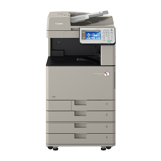
Product Overview ■ Product Lineup ■ Features ■ Specifications ■ Parts Name Product Overview... - Page 17 Product Overview > Product Lineup > Host machine Product Lineup Host machine < Product name > Positioning imageRUNNER ADVANCE C3330 / C3325 / C3320 B/W Linup Color Lineup Underlined (2-digit) numeric figures indicate print speed (ppm: print per minute). C3330 C3325 C3320 Print Speed...
- Page 18 Product Overview > Product Lineup > Option > Pickup / Delivery / Image Reading System Options Option Product name Condition [1][2] imageRUNNER ADVANCE ■ Pickup / Delivery / Image Reading System Options C3330/C3325/C3320 [3] DADF-AQ1 Cannot be installed with Platen Cover Type U. [4] Platen Cover Type U Cannot be installed with DADF-AQ1.
- Page 19 Product Overview > Product Lineup > Option > Function expansion system options ■ Function expansion system options Product name Condition [1] Utility Tray-A2 Cannot be installed with Voice Operation Kit-C2. [2] Copy Card Reader-F1 Copy Card Reader Attachment-B4 is required. Cannot be installed with Copy Control Interface Kit-A1.
-
Page 20: Toner Container
Product Overview > Features > Characteristics > Toner Container Features Characteristics ■ Toner Container Product Features This equipment uses IAP (Insulated & Air Pressure) toner bottles. Characteristics Description Improved serviceability Improved usability Improved serviceability Toner supply mouth: Smaller diameter Toner soiling-resistant, soiling-resistant ADF Pickup/ Separation Main Controller Toner Container... - Page 21 Product Overview > Features > Characteristics > Item Numbers of Consumables Specified on Host Machine (reinforcement of the association between the host machine and the consumables) ■ Improved Replaceability of Consumables ■ Item Numbers of Consumables Specified on Host Machine (reinforcement of the association between the host machine Drum Unit ADF Pickup/...
-
Page 22: Drum Unit
Product Overview > Features > Characteristics > Item Numbers of Consumables Specified on Host Machine (reinforcement of the association between the host machine and the consumables) < Labels > < Package > Item number labels have also been added to the host machine, and can be checked. Describing the same item number also on the part's package enhances the association between the part and the host machine at the user site. -
Page 23: Setup Guide
Product Overview > Features > Characteristics > Setup Guide ■ Maintenance Video for Consumables Replacement ■ Setup Guide Videos are adopted to guide users with an easy-to-understand navigation of the replacement Setup Guide is designed to improve the workability during the installation by enabling to so that they can replace parts correctly without performing any wrong operation. - Page 24 Product Overview > Features > Characteristics > Update of Setting Values without Restarting ■ Introduction of Situation Mode ■ Limiting of Color Printing Situation mode has been newly provided to improve the workability and searchability of Even if an error attributed to the Developing Unit or drum of any of the Y/M/C colors has service technicians at the site.
-
Page 25: Specifications ----------------------------------------------------------------
Product Overview > Specifications > Specifications 1-10 Specifications Paper type Cassette Thin (52 to 63 g/m ), Plain 1 (64 to 75 g/m ), Plain 2 (76 to 90 g/m ), Plain 3 (91 to 105 g/m ), Recycled 1 (64 to 75 g/m ), Recycled 2 (76 to 90 g/m ), Recycled 3 (91 to... - Page 26 (At a room temperature of 20 deg C in all above cases.) 12" x 18" 7 sheets/minute 11" x 17" 15 sheets/minute 15 sheets/minute 30 sheets/minute Weight and Size EXEC 20 sheets/minute imageRUNNER ADVANCE C3325 Series 15 sheets/minute Width Depth Height Weight 15 sheets/minute Product name (mm) (mm) (mm) Approx.
-
Page 27: Paper Type
Product Overview > Specifications > Paper type 1-12 Paper type Following shows the types of usable papers. See the table below for the custom paper size. Type Feeding direction (mm) Width direction (mm) Custom paper size 0-2 139.7 to 147.9 Custom paper size 0-3 148 to 215.9 98.4 to 119.9... - Page 28 Product Overview > Specifications > Paper type > Pickup 1-13 ■ Pickup Feeding Width Pickup position Paper Type Size direction direction Multi CST1 CST2 CST3 CST4 (mm) (mm) Thin paper (52 to 63 g/m Plain paper 1 (64 to 75 g/m Plain paper 2 (76 to 90 g/m Plain paper 3 (91 to 105 g/m Color paper (64 to 82 g/m...
- Page 29 Product Overview > Specifications > Paper type > Pickup 1-14 Feeding Width Pickup position Paper Type Size direction direction Multi CST1 CST2 CST3 CST4 (mm) (mm) Heavy paper 1 (106 to 128 g/m Heavy paper 2 (129 to 163 g/m Heavy paper 3 (164 to 220 g/m 11x17 431.8...
- Page 30 Product Overview > Specifications > Paper type > Pickup 1-15 Feeding Width Pickup position Paper Type Size direction direction Multi CST1 CST2 CST3 CST4 (mm) (mm) Heavy paper 4 (221 to 256 g/m 11x17 431.8 279.4 355.6 215.9 215.9 279.4 LTRR 279.4 215.9...
- Page 31 Product Overview > Specifications > Paper type > Pickup 1-16 Feeding Width Pickup position Paper Type Size direction direction Multi CST1 CST2 CST3 CST4 (mm) (mm) 1-Side Coated Paper 1 (106 to 128 1-Side Coated Paper 2 (129 to 163 1-Side Coated Paper 3 (164 to 220 Duplex Coated Paper 1 (106 to 128 Duplex Coated Paper 2 (129 to 163...
- Page 32 Product Overview > Specifications > Paper type > Pickup 1-17 Feeding Width Pickup position Paper Type Size direction direction Multi CST1 CST2 CST3 CST4 (mm) (mm) Tracing (64 to 99 g/m 11x17 431.8 279.4 355.6 215.9 215.9 279.4 LTRR 279.4 215.9 STMTR 215.9...
- Page 33 Product Overview > Specifications > Paper type > Pickup 1-18 Feeding Width Pickup position Paper Type Size direction direction Multi CST1 CST2 CST3 CST4 (mm) (mm) Labels (118 to 185 g/m 11x17 431.8 279.4 355.6 215.9 215.9 279.4 LTRR 279.4 215.9 STMTR 215.9...
- Page 34 Product Overview > Specifications > Paper type > Pickup 1-19 Feeding Width Pickup position Paper Type Size direction direction Multi CST1 CST2 CST3 CST4 (mm) (mm) Pre-Punched paper (64 to 75 g/m 11x17 431.8 279.4 355.6 215.9 215.9 279.4 LTRR 279.4 215.9 STMTR...
- Page 35 Product Overview > Specifications > Paper type > Pickup 1-20 Feeding Width Pickup position Paper Type Size direction direction Multi CST1 CST2 CST3 CST4 (mm) (mm) Envelope (75 to 105 g/m COM10_R 241.3 104.7 Monarch_R 190.5 98.4 ISO-C5_R DL_R Nagagata 3_R Younagagata 3_R Kakugata 2_R COM10...
-
Page 36: Control Panel
Product Overview > Parts Name > Control Panel 1-21 Parts Name Control Panel Touch Panel Display Energy Saver key Numeric key Cross Sectional View Main Menu Brightness Adjustment Dial Quick Menu Volume Settings key Settings/ Registration key Destination/ Counter Check key Forward Settings Clear key Status Monitor/... - Page 37 Technical Explanation ■ Basic Configuration ■ Document Exposure ■ Main Controller ■ Laser Exposure System ■ Image Formation System ■ Fixing System ■ Pickup / Feed System ■ External Auxiliary System ■ MEAP ■ Embedded RDS ■ Updater ■ DCM Technical Explanation...
-
Page 38: Functional Configuration
Technical Explanation > Basic Configuration > Functional Configuration Basic Configuration Functional Configuration This machine consists of 6 major blocks: Original Exposure and Feed System, Controller System, Laser Exposure System, Image Formation System, Fixing System, and Pickup Feed System. Original Exposure and Feed System Reader Delivery Fixing... -
Page 39: External View
Technical Explanation > Document Exposure > Overview > Cross Section Document Exposure ■ External View Overview [10] ■ Features • Low energy consumption by adopting a new Scanner Unit ■ Specifications Item Specification/function Remarks Exposure system High-brightness white LED + reflection plate Original In BOOK Scan by movement of scanner unit... -
Page 40: Scanner Unit
Technical Explanation > Document Exposure > Overview > Scanner Unit ■ Major Electrical Parts ■ Scanner Unit Original exposure and scanning are performed by the integrated scanner unit of LED, STM1 turndown mirror, free curved mirror, and Reading sensor. HTR01 Light emitted from LED is reflected by the original and reaches the Reading Sensor throughthe Reflection Mirror and the newly developed Lens Unit. - Page 41 Technical Explanation > Document Exposure > Overview > Reader Heater LED lamp unit On LED lamp unit, the light is generated from the 1 LED lamp PCBs (LED chip: 40 pieces per PCB). Generated light is exposed to the original through the reflection plate. Reading sensor The Reading Sensor scans the image per 1 image line.
-
Page 42: Shading Correction
Technical Explanation > Document Exposure > Controls > Image Processing Controls ● Shading Correction Shading correction corrects unevenness of the output of the Reading Sensor. ■ Reading Speed In shading correction, there is a type of shading correction that is executed per job. There are two patterns when the Reading Sensor performs reading depending on the Operating timing: combination of Copyboard/DF and 300 dpi/600 dpi. - Page 43 Technical Explanation > Document Exposure > Controls > Image Processing ● Dust detection / correction control 2) Processing to correct dust (when a regular stream reading job starts, between papers) Dust detection is executed at the reading position, and image density variation (white Overview streaks) in areas of dust is corrected from the next original if there is any dust.
-
Page 44: Original Size Detection
Technical Explanation > Document Exposure > Controls > Original Size Detection ● Change of Magnification Ratio ■ Original Size Detection The scanner performs reading at 600 dpi or 300 dpi. For the color mode, only COLOR mode ● Overview is used; the scanner does not perform reading in B&W mode scanning regardless of the color This machine determines the size of an original by the combination of the measurement mode selected in the Control Panel. - Page 45 Technical Explanation > Document Exposure > Controls > Service Tasks ● Description of Controls ■ Service Tasks In horizontal scanning direction, sensor level of each original detection position is measured ● Service Mode/Adjustment by moving the Scanner Unit to the detection position shown in the figure in relation to the White Level Adjustment original set position.
-
Page 46: Main Controller Pcb
Technical Explanation > Main Controller > Overview > Main controller PCB 2-10 Main Controller ■ Main controller PCB HDD ADF Reader Voice Internal I/F Overview J38 J36 External I/F ■ Configuration / Function DEVICE PORT Main Controller PCB Memory Image Data Analyzer PCB FLASH Laser... -
Page 47: Shutdown Sequence
Technical Explanation > Main Controller > Shutdown Sequence 2-11 Boot Sequence Error codes Error description E602 0001 HDD error HDD fails to be Ready. When the HDD is not formatted Power Supply Switch ON E614 0001 Flash PCB detection error [ ] : Program storage location Unable to recognize the Flash PCB. - Page 48 Technical Explanation > Main Controller > Controls > Network(Advanced Box / Space Client) 2-12 Controls ■ SEND ■ Copy Network Reader To DC Controller Reader Image Processing Resolution Conversion Data Conversion Image rotation JPEG Encode JPEG Conversion/Extension Controller Print the Image Image Processing Processing Resolution Conversion...
-
Page 49: Fax Send
Technical Explanation > Main Controller > Controls > Fax Receive 2-13 ■ Fax SEND Reader Image Processing Resolution Conversion JBIG・MMR/MH Image rotation Conversion Image Level Cell HDD Writing/ Reading Image Data Buffer (Memory) Main Controller PCB F-2-18 ■ Fax Receive To DC Controller Image Processing Color Space Conversion... - Page 50 Technical Explanation > Main Controller > Security > Management Settings of Hard Disk 2-14 Security ● Initialize All Data/Settings Saved files and registered information are initialized. ■ Management Settings of Hard Disk Data saved in the machine such as files, information registered in the address book, job log information and so on can be deleted (initialized).* Besides data of originals that is accumulated using the fax function, this machine's hard disk stores information registered in the address book and password information of the...
- Page 51 Technical Explanation > Main Controller > Security Function (Encryption Key, Certificate and Protection of Password) > Security Information Structure 2-15 Security Function (Encryption Key, Certificate and ■ Security Information Structure Protection of Password) The operation of the security function differs depending on the TPM settings on the UI. There are 2 types of TPM settings, and the respective flows of security information are ■...
- Page 52 Technical Explanation > Main Controller > Security Function (Encryption Key, Certificate and Protection of Password) > Works to be Done Before and After Introduction 2-16 When the TPM settings are disabled, the TPM key becomes invalid, so the security ■ Works to be Done Before and After Introduction information is protected only by the shared key.
- Page 53 Technical Explanation > Main Controller > Security Function (Encryption Key, Certificate and Protection of Password) > Works to be Done Before and After Introduction 2-17 ● Enabling of the Function 2) Restart the machine after clicking "Yes". CAUTION: Be sure to recommend to the user (administrator) to set the System PIN beforehand. After configuring the TPM Settings to "On", back up the TPM key, but it can only be done once.
- Page 54 Technical Explanation > Main Controller > Security Function (Encryption Key, Certificate and Protection of Password) > Works to be Done Before and After Introduction 2-18 ● Backup of TPM key 3) After clicking [Password], enter the password (4 to 12 digits). Then, re-enter the verification password.
- Page 55 Technical Explanation > Main Controller > Security Function (Encryption Key, Certificate and Protection of Password) > Works to be Done Before and After Introduction 2-19 ● Restoration of TPM key CAUTION: Causes of backup failure The operation is almost the same as that of backup. In the following cases, a message indicating that the backup has failed and its cause Differences: are displayed.
- Page 56 Technical Explanation > Main Controller > Security Function (Encryption Key, Certificate and Protection of Password) > Works to be Done Before and After Introduction 2-20 ● Disabling of the Function CAUTION: Causes of restoration failure In the following cases, a message indicating that the restoration has failed and its cause CAUTION: Points to note at disabling the function are displayed.
- Page 57 Technical Explanation > Main Controller > Security Function (Encryption Key, Certificate and Protection of Password) > Target data for encryption/decryption (reference) 2-21 2) Executes "Initialize All Data/Settings" to configure the TPM Setting to "Off". ■ Target data for encryption/decryption (reference) Type Application/Function Security Information...
- Page 58 Technical Explanation > Main Controller > HDD Encryption Kit (option) > Compatibility among Device, Encryption Board and Hard Disk 2-22 HDD Encryption Kit (option) The state of each combination is described here. Case 1: Normal operation When installed, this option generates an encryption key in the Encryption Board to encrypt the Case 2: A hard disk-related error occurs because the system on the hard disk cannot be read whole hard disk, including the system software.
- Page 59 Technical Explanation > Main Controller > HDD Encryption Kit (option) > Overview of Countermeasures for Trouble 2-23 ■ Overview of Countermeasures for Trouble Service task User Data Recovery Countermeasure Hard disk replacement Deleted Replace Hard disk 1) Format hard disk. Encryption Board Deleted Install HDD encryption Kit 1) Replace the Encryption Board.
- Page 60 Technical Explanation > Laser Exposure System > Overview 2-24 Laser Exposure System Overview The laser exposure system forms a static latent image on the Photosensitive Drum by laser exposure. The Laser Scanner Unit consists of the Laser Assembly and the Scanner Motor, and is controlled by the signal from the DC Controller.
- Page 61 Technical Explanation > Laser Exposure System > Specification 2-25 Specification UN08 Item Description Wave length 780 to 800 nm Laser type Infrared (invisible) laser UN09 Laser output 10 mW Number of Laser Scanner Units Number of laser beams 1 beam per color/scanning Resolution At full speed: 600 dpi At half speed: 600 or 1200 dpi...
- Page 62 Technical Explanation > Laser Exposure System > 1-Polygon 4-Laser Method 2-26 1-Polygon 4-Laser Method Reflection Mirror UN08 C/Bk Laser Driver PCB This method performs laser scanning using one Scanner Motor and four laser diodes. The Imaging Lens UN09 Y/M Laser Driver PCB multifaceted mirror on one Scanner Motor can scan lasers equivalent to four stations, thereby Photosensitive Drum Scanner Motor...
-
Page 63: Execution Timing
Technical Explanation > Laser Exposure System > Controls > Laser ON/OFF control 2-27 Controls ■ Laser ON/OFF control ● Purpose ■ Overview Turns the laser beam ON and OFF according to the combination of laser control signals. Item Operation description Laser ON/OFF control Turns the laser beam ON and OFF according to the combination ●... - Page 64 Technical Explanation > Laser Exposure System > Controls > Horizontal scanning synchronous control 2-28 ■ Horizontal scanning synchronous control C/K Laser Driver PCB (UN09) BD Signal ● Purpose BD Sensor Aligns the write start position in the horizontal scanning direction. APC Signal Bk_VDO ●...
- Page 65 Technical Explanation > Laser Exposure System > Controls > Vertical scanning synchronous control 2-29 ■ Vertical scanning synchronous control ● Purpose Aligns the write start position in the vertical scanning direction. ● Execution Timing Laser Laser At each print Laser Laser ●...
-
Page 66: Image Mask Control
Technical Explanation > Laser Exposure System > Controls > Laser scanner motor control 2-30 ■ Image mask control ■ Laser scanner motor control ● Purpose ● Purpose Prevents soiling of the Secondary Transfer Outer Roller. Rotates the Scanner Motor at a specific speed. Image mask control is carried out at horizontal scanning and vertical scanning, respectively, to avoid laser beams from emitting outside of the image area. -
Page 67: Apc Control
Technical Explanation > Laser Exposure System > Controls > APC(Auto Power Control) control 2-31 ■ APC(Auto Power Control) control Related Error Code: ● Purpose E100-0001: BD error Ensures constant laser beam light intensity for each line. The BD lock was unlocked although it had been locked once. E110-0001: Scanner Motor error ●... - Page 68 Technical Explanation > Laser Exposure System > Controls > BD correction control 2-32 ■ BD correction control Related Error Code: ● Purpose E100-0001: BD error Corrects the displacement of each color's laser write start position due to the varied angle of The BD lock was unlocked although it had been locked once.
- Page 69 Technical Explanation > Image Formation System > Overview > Parts Configuration 2-33 Image Formation System ■ Parts Configuration Overview ■ Specifications Item Function/Method Photosensitive Material Drum Drum diameter 30 mm in diameter Cleaning Cleaning Blade Process speed 1/1 speed: 119.4 mm/s 1/2 speed: 59.7 mm/s Drum Heater None...
-
Page 70: Print Process
Technical Explanation > Image Formation System > Overview > Print Process 2-34 ■ Print Process Static latent image 1 Primary Charging The surface of the Photosensitive Drum is charged to Delivery formation block make a uniform negative potential. Flow of print paper 2 Laser exposure Emission of the laser light forms a static latent image Rotating direction of ITB,... - Page 71 Technical Explanation > Image Formation System > Overview > Bias Types 2-35 ■ Bias Types The following 5 types of bias are used with this machine. Bias Bias name Application location Control PCB types Primary charging bias (DC) DC Primary Charging Roller Secondary Transfer High Voltage PCB (UN03) Developing bias (DC) Developing Cylinder...
- Page 72 Technical Explanation > Image Formation System > Controls > Drum Unit / Developing Unit 2-36 Controls ■ Drum Unit / Developing Unit ● Parts / Drive Configuration ■ Overview Drum Unit / Developing Unit Toner Supply Area Parts / Drive Configuration Parts / Drive Configuration Drum Cleaning / Drum Cleaning Pre- Opening/Closing of Toner Container...
- Page 73 Technical Explanation > Image Formation System > Controls > Drum Unit / Developing Unit 2-37 ● Drum Cleaning / Drum Cleaning Pre-exposure Control Related Service Mode: COPIER > FUNCTION > MIXC-P > PRE-EXP : Lighting-up of Pre-exposure LED COPIER > OPTION > FNC-SW > PREXP-SW : Set Clean Pre-exposure LED light condtn COPIER >...
- Page 74 Technical Explanation > Image Formation System > Controls > Drum Unit / Developing Unit 2-38 ● Drum Unit Detection NOTE: Purpose: To detect whether the Drum Unit is installed Drum Unit detection may not be executed at times such as at recovery from sleep mode (of 8 or more hours).
-
Page 75: Primary Charging
Technical Explanation > Image Formation System > Controls > Drum Unit / Developing Unit 2-39 ● Primary Charging Prior delivery alarm Display to prompt Completion of replacement replacement Primary charging bias control Timing • Y/M/C/K-DRM-LF (*1) 7 days after pre-toner low When the Drum Unit is Purpose: To apply voltage to the Primary Charging Roller in order to charge the = 100% (initial value) - Page 76 Technical Explanation > Image Formation System > Controls > Transfer/Separation 2-40 Developing bias control ■ Transfer/Separation Purpose: To apply voltage to the Developing Cylinder in order to generate a potential ● Parts / Drive Configuration difference from the Photosensitive Drum Control description The developing bias (AC, DC negative), which has been generated on the Secondary Charging PCB (UN03), is applied to the Developing Cylinder.
- Page 77 Technical Explanation > Image Formation System > Controls > Transfer/Separation 2-41 ● Primary Transfer Control Primary transfer bias control Primary Transfer ATVC Purpose: To apply current to the Primary Transfer Roller Purpose: To set the transfer voltage required to obtain the target transfer current value in The primary transfer bias is divided into each color (Y/M/C/Bk), and is generated by the order to prevent transfer failure due to environmental changes Primary Transfer High Voltage PCB (UN02) and applied to the Primary Transfer Roller.
- Page 78 Technical Explanation > Image Formation System > Controls > Transfer/Separation 2-42 ● Secondary Transfer Control ● Primary Transfer Roller Disengagement Control Secondary Transfer ATVC Purpose: To disengage the color Primary Transfer Roller in the single color Bk mode in order Purpose: To set the transfer voltage required to obtain the target transfer current value in to increase the life of image formation parts (Photosensitive Drum, ITB) order to prevent transfer failure due to environmental changes and paper type...
- Page 79 Technical Explanation > Image Formation System > Controls > Transfer/Separation 2-43 Primary transfer disengagement initialization Status of each mode/timing to enter each mode Initialization is performed so that the coupling is securely engaged at power-on and when the Mode to shift State Shift timings door is closed because the state of the primary transfer disengagement is not determined.
-
Page 80: Itb Cleaning
Technical Explanation > Image Formation System > Controls > Transfer/Separation 2-44 ● ITB Displacement Correction ● ITB Cleaning Purpose: To correct ITB displacement Purpose: To remove residual toner on the ITB Control description: 1) The ITB Cleaning Blade scrapes toner on the ITB. 2) The scraped toner is fed to the Waste Toner Container by the ITB Cleaning Screw. - Page 81 Technical Explanation > Image Formation System > Controls > Transfer/Separation 2-45 ● Secondary Transfer Outer Roller Cleaning Control Control timing Adjustment timing Conditions At initial installation At power-on At initial installation Purpose: To prevent transfer failure and soiling at the back of the paper caused by soiling of When Settings/Registration is Adjustment/Maintenance >...
-
Page 82: Image Stabilization Control
Technical Explanation > Image Formation System > Controls > Image Stabilization Control 2-46 ■ Image Stabilization Control ● Control Timing List Execution items for image stabilization control differ according to the environment and ● Overview condition of image formation parts. Purpose: To control to prevent image failure due to change of the environment or deterioration Following shows the control items at each sequence. - Page 83 Technical Explanation > Image Formation System > Controls > Image Stabilization Control 2-47 ● Laser Power Correction (D-max) Control ● Color Displacement Correction Control Purpose: To determine the optimal laser output Purpose: To correct color displacement caused by uneven exposure (skew/bent) from the Laser Scanner Unit or uneven rotation of the drum/ITB Control description: Control description: Color displacement is corrected by forming a patch for color displacement...
- Page 84 Technical Explanation > Image Formation System > Controls > Image Stabilization Control 2-48 ● Patch Sensor Adjustment NOTE: Purpose: To perform correction of the Patch Sensor light intensity and sampling of the ITB Short pattern is normally used as the patch pattern used when performing color displacement correction.
- Page 85 Technical Explanation > Image Formation System > Controls > Toner Supply Area 2-49 ● Auto Gradation Adjustment (PASCAL) Control ■ Toner Supply Area Purpose: To stabilize gradation density characteristics of the image ● Parts / Drive Configuration This control is executed when "Auto Adjust Gradation > Full Adjust" is selected in the Settings/ Toner is supplied from the Toner Container to the Developing Unit.
- Page 86 Technical Explanation > Image Formation System > Controls > Toner Supply Area 2-50 ● Opening/Closing of Toner Container Shutter ● Bottle State Detection Purpose: To automatically open and close the Toner Container shutter Purpose: To detect the state of the Toner Container The Bottle New/Old Detection Sensor (Y/M/C/Bk) (UN39/UN40/UN41/UN42) detects the state Toner Head Assembly from the IC tag of the Toner Container.
- Page 87 Technical Explanation > Image Formation System > Controls > Toner Supply Area 2-51 ● Toner Container Detection Toner Supply Sensor Toner Log Connector Presence/absence of the Toner Container is detected. PS26,27,28,29 UN39,40,41,42 The Toner Supply Sensor (Y/M/C/Bk) (PS26/PS27/PS28/PS29) is arranged as shown in the figure below;...
- Page 88 Technical Explanation > Image Formation System > Controls > Toner Supply Area 2-52 ● Toner Supply Control This machine has only 2 Toner Bottle Motors, and toner is supplied by driving Toner Bottles of two colors alternately by one motor. Purpose: To supply toner in the Toner Container to the Developing Unit The following shows the image of the Drive Unit viewed from the back side.
- Page 89 Technical Explanation > Image Formation System > Controls > Toner Supply Area 2-53 3. When the motor rotates in the reverse direction, the Swing Gear moves to the opposite Parts name direction. Flag Toner Container 4. The driving force is transmitted only to the gears on the side toward which the gear moved, Cut-off and the Toner Bottle rotates and toner is supplied.
- Page 90 Technical Explanation > Image Formation System > Controls > Toner Supply Area 2-54 ● Toner Level Detection ● Detection of Completion of Toner Replacement Display Remaining Toner Detection of the completion of replacement Prior delivery alarm Empty toner Detection timing When a replacement of Toner Container is detected error Detected to (location)
- Page 91 Technical Explanation > Image Formation System > Controls > Waste Toner Feed Unit 2-55 ■ Waste Toner Feed Unit Parts name Role SW01 Waste toner container Waste Toner Container is detected ● Parts / Drive Configuration detection switch Waste toner in the Drum Unit and ITB Cleaning Unit is fed to the Waste Toner Container. ●...
-
Page 92: Other Controls
Technical Explanation > Image Formation System > Controls > Other Controls 2-56 ● Detection of Completion of Waste Toner Replacement ■ Other Controls Detection timing When the Waste Toner Sensor PCB (UN30) is turned ON after the Cassette 1 is ●... - Page 93 Technical Explanation > Image Formation System > Controls > Other Controls 2-57 Transparency black band sequence ● Behavior When Color Printing is Limited or There is No Color Toner Control timing Conditions This is a function to enable B&W printing and copying without stopping the entire printing At paper interva For each 10 sheets of transparency function when an error attributed to the Y/M/C Developing Unit or when there is no Y/M/C...
- Page 94 Technical Explanation > Fixing System > Overview > Specifications 2-58 Fixing System ■ Specifications Item Function/Method Fixing method On-demand fixing Overview Fixing speed 119.4 mm/s (1/1 speed) 59.7 mm/s (1/2 speed) This machine uses the on-demand fixing method. Heater Ceramic Heater The Main Heater (heat distribution: high at center) and the Sub Heater (heat distribution: high at edges) are individually driven.
-
Page 95: Major Components
Technical Explanation > Fixing System > Overview > Major Components 2-59 ■ Major Components Part Name Function/Method Fixing Pressure Roller A toner image on paper is fixed by applying heat/pressure. Fixing Film Unit Fixing Main Heater For heating the center of Fixing Film (Ceramic Heater) Fixing Sub Heater For heating the edges of Fixing Film (Ceramic Heater) This is engaged with Heater. - Page 96 Technical Explanation > Fixing System > Controls > Standby Temperature Control 2-60 Controls ■ Standby Temperature Control ■ Overview of Fixing Temperature Control Fixing temperature STBY INTR PRNT Fixing temperature STBY INTR PRNT Flaying start control Startup Sheet-t temperature During-print (warm-up o-sheet Flying start...
- Page 97 Technical Explanation > Fixing System > Controls > Print Temperature Control 2-61 ■ Print Temperature Control ● Print temperature control An appropriate target temperature is set according to the number of sheets, paper type, and environment at continuous printing. Fixing STBY INTR PRNT...
- Page 98 Technical Explanation > Fixing System > Controls > Print Temperature Control 2-62 Target temperature during printing <when paper width exceeds 300 mm> Related Service Mode: Fixing Target temperature Paper weight Paper Width Resolution Paper type speed (deg C) • Display of Thermistor detection temperature (g/m (mm) (dpi)
- Page 99 Technical Explanation > Fixing System > Controls > Down Sequence Control 2-63 ■ Down Sequence Control Printing speed <when paper width is 300 mm or less> Target temperature ● Down Sequence When Feeding Small-size Paper Paper weight Resolution Fixing speed Print speed Paper type (deg C)
- Page 100 Technical Explanation > Fixing System > Controls > Down Sequence Control 2-64 Printing <when paper width exceeds 300 mm> ● Down Sequence When Using Paper of Mixed Size and Mixed Type Purpose: Paper Paper Fixing Target temperature Resolution Print speed Paper type weight Width...
- Page 101 Technical Explanation > Fixing System > Controls > Film Unit Engagement/Disengagement Control 2-65 ■ Film Unit Engagement/Disengagement Control Execution condition/timing of engagement Execution condition/timing of disengagement operation: operation: The Fixing Film Unit is disengaged from the Fixing Pressure Roller under a specific condition •...
- Page 102 Technical Explanation > Fixing System > Controls > Fixing Arch Control 2-66 ■ Fixing Arch Control Sensor : OFF Sensor : ON Slack of paper is small Slack of paper is large Purpose : To prevent image failure/feed failure Operation: The slack that occurs when paper is fed from the Secondary Transfer Outer Roller to the Fixing Pressure Roller is kept to a specified level.
- Page 103 Technical Explanation > Fixing System > Controls > Fixing Unit Life Detection 2-67 ■ Fixing Unit Detection When these conditions reach certain limits "The fixing assembly needs to be replaced." is displayed on the Control Panel status line. During warm-up rotation (at power-on/recovery from sleep mode/closing of the cover), the Fixing Unit detection signal (FSR-CNCT-THX) is input to the DC Controller to detect the Fixing Unit.
-
Page 104: Protection Function
Technical Explanation > Fixing System > Controls > Protection function 2-68 ■ Detection of whether the Fixing Unit is new ■ Protection function Clearing The Fixing Fuse PCB (UN31) detects whether the Fixing Unit is new. Code Description of error Fixing Fuse PCB (UN31) Fuse present: Fixing Unit is new E001 Detection of abnormal high temperature Fixing Fuse PCB (UN31) Fuse not present: Fixing Unit is being used... - Page 105 Technical Explanation > Fixing System > Controls > Protection function 2-69 Clearing Code Description of error E009 Fixing Film Unit engagement/disengagement error 0000 The Fixing Pressure Release Sensor did not detect ON status within 10 sec after the start of pressure application operation for fixing. needed.
- Page 106 Technical Explanation > Pickup / Feed System > Overview > Specifications 2-70 Pickup / Feed System ■ Specifications Item Description Pickup method Cassettes 1 and 2 Retard separation method (Pickup Roller + Feed Roller + Overview Separation Roller) Multi-purpose Tray Retard separation method (Pickup Roller + Feed Roller + ■...
- Page 107 Technical Explanation > Pickup / Feed System > Overview > Parts Configuration 2-71 ■ Parts Configuration ● Layout Drawing of Sensors ● Layout Drawing of Rollers [PS53] [PS52] [PS51] [PS12] [21] [PS14] [PS10] [10] [12] [11] [22] [13] [14] [PS22] [15] [20] [16]...
- Page 108 Technical Explanation > Pickup / Feed System > Overview > Parts Configuration 2-72 ● Diagram of load drives Without 3-Way Unit When the 3-Way Unit is connected SL06 SL06 F-2-91 F-2-90 Cassette 1,2 Pickup Motor SL06 Duplex Reverse Solenoid Cassette 1,2 Pickup Motor Cassette 1,2 Feed / Multi-purpose Pickup Motor Fixing Motor Fixing Motor...
-
Page 109: Paper Path
Technical Explanation > Pickup / Feed System > Overview > Paper Path 2-73 ■ Paper Path Without 3-Way Unit 1/1 speed : 200mm/sec When the 3-Way Unit is connected 1/2 speed : 100mm/sec Acceleration section 1/1 speed : 200mm/sec 1/2 speed : 100mm/sec Acceleration section Reverse Mouth Reverse Mouth... - Page 110 Technical Explanation > Pickup / Feed System > Controls > Overview 2-74 Controls ■ Overview Area Detection, Control Cassette Pickup Assembly Lifter control Reverse • Cassette 1 Cassette Pickup Control /Duplex Assembly • Cassette 2 Cassette Paper Size Detection/Cassette Detection Paper level/presence detection Multi-purpose Tray Pickup Multi-Purpose Tray Pickup Control...
-
Page 111: Cassette Pickup Assembly
Technical Explanation > Pickup / Feed System > Controls > Cassette Pickup Assembly 2-75 ■ Cassette Pickup Assembly ● Drive Configuration ● Parts Configuration PS04 PS08 PS05 PS18 PS17 SW13 F-2-96 Cassette 1 Pickup Roller Cassette 1,2 Lifter Motor Cassette 1 Vertical Path Roller Cassette 1,2 Pickup Motor PS06 Cassette 1 Feed Roller... - Page 112 Technical Explanation > Pickup / Feed System > Controls > Cassette Pickup Assembly 2-76 ● Lifter control ● Cassette Paper Size Detection/Cassette Detection Paper inside a cassette is lifted up by the Lifting Plate. Result of automatic Paper Size Group for Auto Recog. in Drawer*1 The Middle Plate is lifted by the rotation of the Cassette Lifter Motor (M06/M102).
- Page 113 Technical Explanation > Pickup / Feed System > Controls > Cassette Pickup Assembly 2-77 *2: Preferences > Paper Settings > A5R/STMTR Paper Selection *3: Cassette 1: (Lv.2) COPIER > OPTION > CST > CST-K-SW Cassettes 2 to 4: (Lv.2) COPIER > OPTION > CST > Cx-K-SW Cassette 1 The Cassette 1 Size Switch detects the size of the paper loaded in the cassette.
- Page 114 Technical Explanation > Pickup / Feed System > Controls > Cassette Pickup Assembly 2-78 Cassette 2 SW15 The paper size in the cassette is automatically detected by the Cassette 2 Size Switch A/ B after the position of the Guide Plate is adjusted. The switch consists of 3 microswitches, and length and width are detected in accordance with the combination of ON/OFF.
- Page 115 Technical Explanation > Pickup / Feed System > Controls > Cassette Pickup Assembly 2-79 ● Paper level/presence detection The level and presence of paper in the cassette are detected by four sensors. PS05 • Paper Level Sensor A • Paper Level Sensor B •...
- Page 116 Technical Explanation > Pickup / Feed System > Controls > Cassette Pickup Assembly 2-80 Cassette 1 Cassette 2 PS04 PS06 PS05 PS07 PS18 PS20 PS19 PS17 F-2-100 Lifter Gear PS04 Cassette 1 Lifter Sensor Paper Detection Lever PS05 Cassette 1 Paper Sensor Middle Plate PS17 Cassette 1 Paper Level Sensor A...
- Page 117 Technical Explanation > Pickup / Feed System > Controls > Multi-purpose Tray Pickup Assembly 2-81 ■ Multi-purpose Tray Pickup Assembly ● Multi-Purpose Tray Pickup Control Paper is picked up from the Multi-purpose Tray by the reverse rotation of the Cassette 1,2 ●...
- Page 118 Technical Explanation > Pickup / Feed System > Controls > Multi-purpose Tray Pickup Assembly 2-82 ● Multi-purpose Tray Automatic Size Detection Automatic size detection is performed by three sensors. The paper size to be automatically detected which is mentioned above is determined by •...
- Page 119 Technical Explanation > Pickup / Feed System > Controls > Fixing/Registration Assembly 2-83 ■ Fixing/Registration Assembly ● Registration Control Purpose: To correct paper skew / align the leading edges of image and paper ● Parts / Drive Configuration Skew correction control The paper leading edge runs into the stopped Registration Roller, thereby generating an arch in order to correct the skew.
- Page 120 Technical Explanation > Pickup / Feed System > Controls > Reverse / Delivery Assembly 2-84 The feed control to align the leading edge of paper with the leading edge of image uses ■ Reverse / Delivery Assembly the Pre-Registration Sensor as the reference for detecting the leading edge, by selectively ●...
- Page 121 Technical Explanation > Pickup / Feed System > Controls > Reverse / Delivery Assembly 2-85 Without 3-Way Unit ● The number of circulating sheets, feed path and reverse/standby control at 1-sided/2-sided feeding With this machine, the number of circulating sheets, feed route, reverse position and standby position (1- and 2-sided) differ according to the set length of fixed size paper and delivery outlet.
-
Page 122: Jam Detection
Technical Explanation > Pickup / Feed System > Controls > Jam Detection 2-86 When 3-Way Unit-D1 is not installed ■ Jam Detection Feed route is only short path when the 3-Way Unit is not installed. Yes: Detected, No: Not detected Number of Jam Type (xx)* IO >... - Page 123 Technical Explanation > External Auxiliary System > Controls > Software Counter Control 2-87 External Auxiliary System Number displayed for each counter (in service mode)/Item Target Counter Counter Target country Counter 2 Counter 3 Counter 4 Counter 5 Counter 6 7 / 8 code Controls Total...
- Page 124 Technical Explanation > External Auxiliary System > Controls > Software Counter Control 2-88 Number displayed for each counter (in service mode)/Item Target Country Country Country Country Country Country Counter Counter Target country code code code Counter 2 Counter 3 Counter 4 Counter 5 Counter 6 7 / 8 code Japan...
-
Page 125: Fan Control
Technical Explanation > External Auxiliary System > Controls > Fan Control 2-89 ■ Fan Control ● Speed Control Of the fans installed in this machine, the Front Fan (FM01), the Motor Fan (FM03), the Power ● Location of Fans Supply Cooling Fan (FM02) and the Controller Fan (FM04) are subject to speed control. Each controller switches voltages to switch the fan rotation speed. -
Page 126: Power Supply
Technical Explanation > External Auxiliary System > Controls > Power supply 2-90 ■ Heater Control ■ Power supply Name Function Remarks ● Internal power supply Cassette Heater (host machine) Prevents paper in the Cassettes 1/2 Option for EUR/USA/LTN from absorbing moisture Main Power SW Cassette Heater (Cassette Prevents paper in the Cassettes 3/4... - Page 127 Technical Explanation > External Auxiliary System > Controls > Energy Saving Function 2-91 ■ Energy Saving Function Standby Mode The mode in which the machine is running or can start operation immediately and all power is ● Overview supplied. There are "Standby" mode and "Sleep" mode as the power supply mode of this machine. When turning OFF the Control Panel Power Switch or the specified period of time has Further, "Sleep"...
- Page 128 Technical Explanation > External Auxiliary System > Controls > Energy Saving Function 2-92 ● Conditions for Not Entering Deep Sleep Mode (Check Items) The timer is running The sleep mode exit timer is running (for 15 seconds after exiting Deep Sleep). Settings in Settings/Registration The hard disk drive protection timer is running (for 10 minutes after exiting from Deep Sleep and Preferences >...
- Page 129 Technical Explanation > External Auxiliary System > Controls > Quick Startup 2-93 ■ Quick Startup Disconnect the plug from outlet when performing work with the possibility to come in contact with the PCBs above. If a conductive material comes in contact with the PCB, short circuit For faster startup, the power configuration of this machine always supplies power to the Low may occur in the PCB, and may cause damage on it.
- Page 130 Technical Explanation > External Auxiliary System > Controls > Effect of the Hub Which Supports Spanning Tree 2-94 ■ Effect of the Hub Which Supports Spanning Tree At first startup after the power plug is connected to the outlet Others When the network is connected in a loop, data transfer efficiency may be lowered due to •...
-
Page 131: Function Overview
Technical Explanation > MEAP > Login Service and User Authentication Method > User Authentication (UA) 2-95 MEAP Login Service and User Authentication Method A login service is a service for authenticating users when they use a device that supports Function Overview MEAP. - Page 132 Technical Explanation > MEAP > Login Service and User Authentication Method > User Authentication (UA) 2-96 ● PC Environment of Administrator Users and General Users Network ports used Network Ports Used when Using Active Directory The environment required for using a device operated with User Authentication from a PC on a network is indicated below.
- Page 133 SSO provided the automated function conventionally on Security Agent (hereinafter "SA") to authenticate System Manager by allocating IDs set on SA to domain authentication managers (users belonging to Canon Peripheral Admins group). However, User authentication does not support this function.
- Page 134 Technical Explanation > MEAP > Login Service and User Authentication Method > User Authentication (UA) 2-98 ● Server authentication (Active Directory authentication) ● Server Authentication (LDAP Authentication) It is one of the user authentication methods using SSO-H. User authentication is performed It is one of the user authentication methods using UA is performed with the device linked with with the device linked with a domain controller on the network in an Active Directory the LDAP Server on the network in an LDAP environment.
- Page 135 Technical Explanation > MEAP > Login Service and User Authentication Method > User Authentication (UA) 2-99 ● User Management with Server Authentication CAUTION: The environment required for using a server to authenticate users with User Authentication is Make sure to set the time of the server and the time of the device to be within a certain indicated below.
- Page 136 Technical Explanation > MEAP > About SMS > RLS Authentication 2-100 About SMS with User Authentication • The protocol used by the SRV record information of the LDAP service is "_tcp" and the ■ Overview service name is "_ldap" • The protocol used by the SRV record information of the Kerberos service is "_udp" and the MEAP has SMS (Service Management Service) as a service for managing login services and service name is "_kerberos"...
- Page 137 [Role Association] setting on the [Settings/Registration] > [Management Settings] > [User Management] > [Authentication Management] > [Preferences] screen of the Remote UI (Canon Peripheral Admins by default). 2) Enter the password in the password entry field, and click the [Log In]. The default password is "MeapSmsLogin."...
- Page 138 Technical Explanation > MEAP > About SMS > Resources availability (remaining amount) 2-102 ■ Preparation of PC for Accessing SMS ■ Initial Display Languages of SMS ● Checking of operation environment The SMS of this device supports English, Japanese, French, Italian, German, Spanish, Simplified Chinese, Traditional Chinese, and Korean.
- Page 139 Technical Explanation > MEAP > About SMS > Managing the License File 2-103 ■ What is MEAP Specifications (MEAP Spec Version)? Enterprise Service Manager, matching of MEAP Specifications is executed on the side of MEAP platform machine. The machine which doesn't support the version declared by the MEAP Specifications is one of the information required to judge whether MEAP applications application rejects installation of such an application.
-
Page 140: System Information
Application Name: C-Cabinet Gateway for MEAP Application ID/System Application Name: 03a46668-63e4-4636-9cbb-492b6cef05d5 Application Version: 1.0.0 Status: Resolved Installed on: Tue Oct 21 14:00:11 GMT+09:00 2003 Vendor : Canon Inc. License Status : Installed Maximum Memory Usage : 1024 Registered Service : item... - Page 141 Technical Explanation > MEAP > About SMS > MEAP Application Setting Information Management and Log Management 2-105 ■ MEAP Application Setting Information Management and Log ● Advantages Obtained When Using the Services By using MEAP Application Configuration Service and MEAP Application Log Service, as long Management as the MEAP application supports these services, you can perform data management tasks ●...
- Page 142 Technical Explanation > MEAP > Settign Procedure > Preparation 2-106 Settign Procedure ■ Integrated Authentication Function ● Sharing the Authentication Information ■ Preparation Separately managing the authentication information at login and the authentication ● Network configuration process information for MEAP applications creates inconveniences such as that the authentication In order to provide support for the machine via network such as SMS, the network settings process is executed many times.
- Page 143 Technical Explanation > MEAP > Settign Procedure > Preparation 2-107 ● Network Port Change Procedure CAUTION: The default port of the HTTP server used for MEAP and MEAP applications to provide the • To type text using the Web browser, use the characters compatible with the MEAP servlet function is 8000, and the HTTPS server's default port is 8443.
- Page 144 Technical Explanation > MEAP > Settign Procedure > Procedure to Install Applications 2-108 ■ Procedure to Install Applications Note: The license file is provided in text file format, enabling to view in a text editor. The 1) Long on to SMS, and click [Install MEAP Application] on the menu. application ID and device serial number shown in the file allow users to confirm which 2) Perform the following settings, and click [Install].
- Page 145 Technical Explanation > MEAP > Settign Procedure > Procedure to Start and Stop a MEAP Application 2-109 4) Some applications show a screen to indicate the terms of agreement. Read the terms, and ■ Procedure to Start and Stop a MEAP Application click [OK].
- Page 146 Technical Explanation > MEAP > Settign Procedure > Procedure Adding a License File 2-110 ■ Procedure Adding a License File 5) Click [Install]. 1) Log on to SMS 2) On MEAP Application Management, click the name of the application to which you want to add a license file.
- Page 147 Technical Explanation > MEAP > Settign Procedure > Procedure Disabling a License File (suspending a license) 2-111 ■ Procedure Disabling a License File (suspending a license) 3) On Application/ License Information page, click [License Management]. CAUTION: • Since the license file cannot be disabled when the application is still running, the application needs to be stopped before disabling the license file.
- Page 148 Technical Explanation > MEAP > Settign Procedure > Procedure Downloading/ Removing an Invalidated License File 2-112 ■ Procedure Downloading/ Removing an Invalidated License File 3) License Management page appears. To download, click [Download]. Note: The downloaded license file can be used for reinstallation only in the same device (with the same device serial number).
- Page 149 Technical Explanation > MEAP > Settign Procedure > Procedure for Downloading a License for Forwarding 2-113 ■ Procedure for Downloading a License for Forwarding 3) Specify the application to be forwarded. 1) Log in to SMS, stop the application to be forwarded. (see Chapter 2, "Procedure to Start and Stop a MEAP Application.".) F-2-146 4) On Application / License Information page, click [License Management].
- Page 150 Technical Explanation > MEAP > Settign Procedure > Steps to Change Login Services 2-114 7) When [Download] on the [Download / Delete Transfer License File] becomes effective, click ■ Steps to Change Login Services [Download]. 1) Log on to SMS, click [ Enhanced System Application Management ]. 2) Click [SWITCH] for the login service to be used.
- Page 151 Technical Explanation > MEAP > Settign Procedure > Login Service Uninstallation Procedure 2-115 ■ Login Service Installation Procedure ■ Login Service Uninstallation Procedure 1) Log on to SMS, and click the [Browse], and specify the enhanced system application file In order to uninstall a login service, the service needs to be stopped ("Installed" status). and license file.
- Page 152 Technical Explanation > MEAP > Settign Procedure > Setting the method to login to SMS 2-116 ■ Setting the User Authentication Method ■ Setting the method to login to SMS In the case of User Authentication, it is possible to use a combination of multiple The procedure for changing the login method for SMS is indicated below.
- Page 153 Technical Explanation > MEAP > Settign Procedure > Disabling the Integrated Authentication Function 2-117 ■ Changing SMS Login Password ● Remote UI Access [Authentication Management] screen to disable integrated authentication from the 1) Log in to SMS, and select [Chage Password]. Remote UI.
- Page 154 In doing so, he/she needs to register the license access number of the application and the serial number of the device. http://www.canon.com/lms/license/ 2-118 Technical Explanation > MEAP > Settign Procedure > Check Procedure...
- Page 155 Technical Explanation > MEAP > Settign Procedure > Check Procedure 2-119 ● Printing the System Information of a MEAP Application ● MEAP Application Information MEAP system information can be printed out with device for confirmation. 1) Log in to SMS, select [MEAP Application Information]. 2) The MEAP application information screen appears.
- Page 156 Technical Explanation > MEAP > Maintenance > Backup of the MEAP Application Area and Recovery of the Backup Data Using SST 2-120 Maintenance ● Backup Item Automatically Copied The following data are backed up using SST: ■ Backup of the MEAP Application Area and Recovery of the The following data are backed up (saved as Meapbackup.bin) using SST.
- Page 157 MEAP application installed. In the support departments of regional headquarters of Canon, all license files of the applications that have been issued are filed according to device serial numbers, enabling you to obtain a series of license files through a single screen as long as you can identify the serial number of the device in question.
- Page 158 Technical Explanation > MEAP > Maintenance > Formatting and Replacing the HDD 2-122 ● Formatting the HDD ● HDD replacement procedure Procedure to format the hard disk If the MEAP application area cannot be backed up Follow the following procedure to format the HDD. If the HDD does not function correctly due to failure or for other reason, the MEAP application area cannot be backed up.
- Page 159 Technical Explanation > MEAP > Maintenance > Using USB Devices 2-123 If the MEAP application area can be backed up ■ Using USB Devices If the MEAP application area can be backed up, it can be recovered after replacing the HDD, ●...
- Page 160 Technical Explanation > MEAP > Maintenance > Using USB Devices 2-124 Availability for MEAP application of the USB device A (either HID keyboard or Mass Storage) Operating mode Software keyboard Conventional USB System driver plugged to device settings [Use MEAP application keyboard enabled MEAP supported MEAP...
- Page 161 Technical Explanation > MEAP > Maintenance > Using USB Devices 2-125 Specifications for the use of USB keyboards ● Initialization of MEAP driver priority registration Characters that could be entered on the software keyboard displayed on the conventional When any trouble occurs regarding USB driver settings and it is necessary to reset the setting control panel can be entered using a USB connected keyboard.
- Page 162 Technical Explanation > MEAP > Maintenance > Using USB Devices 2-126 USB device information Content E:Endpoint Display the information of the USB device, which the device recognized. The Endpoint information of a USB device is shown. If not displayed, there may be some fault occurred. Some of standard optional devices are not displayed on a report.
- Page 163 Technical Explanation > MEAP > Troubleshooting > When SMS Cannot Be Accessed 2-127 Troubleshooting ● If login is not possible due to exclusive control Since access to SMS is under exclusive control, you cannot log in if another user has already ■...
- Page 164 Technical Explanation > MEAP > Troubleshooting > Points to Note When Enabling the [Quick Startup Settings for Main Power] Setting 2-128 ■ How to Deal with a Message "Certificate Error" That Appears at ■ Points to Note When Enabling the [Quick Startup Settings for the Time of Access Main Power] Setting When accessing from the browser to SMS, a message "Certificate Error"...
- Page 165 Technical Explanation > MEAP > Troubleshooting > MEAP Safe Mode 2-129 ● After recovery from quick startup, MEAP applications do not work ■ MEAP Safe Mode properly. ● Outline Some MEAP applications do not process a task at a specified time after quick startup. Use safe mode if you need to start up the system without worrying about extra applications.
- Page 166 Technical Explanation > MEAP > Troubleshooting > Collection of MEAP Console Logs 2-130 ● Starting in Safe Mode 1) Starting in Safe Mode • (Level 2) COPIER > Option > USER > MEAPSAFE. 2) Check that the notation "MPS" has appeared in the upper left corner of the screen; then, restart the device.
-
Page 167: Features And Benefits
Technical Explanation > Embedded RDS > Product Overview > Major Functions 2-131 Embedded RDS ■ Features and benefits E-RDS embedded with a network module in advance can realize a front-end processing Product Overview of e-Maintenance/ imageWARE Remote system without attaching any extra hardware equipment. -
Page 168: Limitations ------------------------------------------------------------------------
Technical Explanation > Embedded RDS > Limitations > Service Mode Menu Transmission Function 2-132 Limitations Transmission timing Transmitting data Error retry When the following service call error is detected. COPIER Display ANALOG ■ Service Mode Menu Transmission Function HV-STS Error codes for transmission: E000 - E00F, // Fixing 1) In the following cases, service mode menu data is not transmitted. - Page 169 Technical Explanation > Embedded RDS > Service cautions 2-133 Service cautions NOTE: *The user can conduct a communication test and seen the communication test result. 1) After clearing RAM of the Main Controller PCB, initialization of the E-RDS setting (ERDS- If the communication results in failure, an error code (a hexadecimal number, 8 digits) DAT) and a communication test (COM-TEST) need to be performed.
- Page 170 Technical Explanation > Embedded RDS > E-RDS Setup > Steps to E-RDS settings 2-134 E-RDS Setup ■ Steps to E-RDS settings 1) In the following service modes, initialize a set value of E-RDS. ■ Confirmation and preparation in advance Select COPIER > Function > CLEAR > ERDS-DAT and touch the [OK] button. To monitor this machine with e-Maintenance/ imageWARE Remote, the following settings are required.
- Page 171 Technical Explanation > Embedded RDS > E-RDS Setup > Steps to Service Browser settings 2-135 3) Enable E-RDS function and execute communication test. ■ Steps to Service Browser settings (a) Select COPIER > Function > INSTALL > E-RDS. 1) In the following service modes, enable a service browser. (b) Press the numeric key [1] on the control panel (the setting value is changed to 1) and Select COPIER >...
- Page 172 Technical Explanation > Embedded RDS > FAQ 2-136 ■ Initializing E-RDS settings It is possible to clear the FLASH data of E-RDS and change the E-RDS setting back to the No.1 default value. Q: In what case does a communication test with UGW fail? A: The following cases can be considered in the becoming "NG!"...
- Page 173 Technical Explanation > Embedded RDS > FAQ 2-137 No.5 No.10 Q: Although Microsoft ISA as a proxy server is introduced, the authentication check is failed. Q: Is there any setting to be made on the device side to enable the service mode menu transmission function? Moreover, what is Service mode menu set as the object of Can E-RDS adopt with Microsoft ISA? A: E-RDS must comply with "Basic"...
- Page 174 Technical Explanation > Embedded RDS > Troubleshooting 2-138 Troubleshooting No.13 No.1 Q: What is the number of the network port used by E-RDS? Symptom: A communication test (COM-TEST) results NG! A: The port number used by E-RDS for communication with UGW is "443". Cause: Initial settings or network conditions is incomplete.
- Page 175 Technical Explanation > Embedded RDS > Troubleshooting 2-139 Remedy 2: Troubleshooting using communication error log (COM-LOG) 3) When each line is selected, the communication error log detailed screen is displayed as 1) Start Service Mode at Level 1. shown in the figure below. (Example: No. 04) 2) Select COPIER >...
- Page 176 Technical Explanation > Embedded RDS > Troubleshooting 2-140 No.3 No.7 Symptom: Registration information of the E-RDS machine was deleted from the device Symptom: The display indicates that the service browser is enabled (BRWS-STS: 1), but the service browser fails to be activated. information on Web Portal, and then registered again.
-
Page 177: Error Code And Strings
Technical Explanation > Embedded RDS > Error code and strings 2-141 Error code and strings Code Character strings Cause Remedy 8700 0306 SRAM AeRDS Improper value is written in Turn the device OFF/ ON. version unmatch! at the head of the NVMEM The following error information is displayed on the communication error log details screen. - Page 178 Technical Explanation > Embedded RDS > Error code and strings 2-142 Code Character strings Cause Remedy Code Character strings Cause Remedy 19 8xxx 2002 URL server A URL different to that Check that the value of URL of 27 8xxx 2028 Server certificate •...
- Page 179 Technical Explanation > Embedded RDS > Error code and strings 2-143 Code Character strings Cause Remedy 35 xxxx xxxx Device internal An internal error, such as Turn the device OFF/ ON. error memory unavailable, etc., Or replace the device system has occurred during a device software.
-
Page 180: Updater ----------------------------------------------------------------------
CDS. 4) Download on e-Maintenance/UGW (called NETEYE in Japan)-enabled devices, firmware can be firmware updated remotely, which effectively slashes costs incurred in field services. Canon Inc. Firmware Upload Updater imageRUNNER Firmware • MEAP Application/System Option Installation ADVANCE... -
Page 181: List Of Functions
PCs. Category Function Mode Registration] linked Checking firmware 1) Manually execute Canon Inc/ compatibility Canon Inc. Updater. 統括販売会社 Checking special firmware Firmware Upload Checking latest firmware Updater ファームウェア... - Page 182 Technical Explanation > Updater > Functional Overview > Distribution Flow 2-146 ■ Distribution Flow ● MEAP Application/System Option Installation Flow MEAP application/system option installation method using service mode is not provided. ● Firmware Installation Flow Be sure to use the [Settings/Registration] to install. Service technicians provide firmware install services in the following 3 methods.
- Page 183 Technical Explanation > Updater > Limitations and Cautions > Cautions 2-147 Limitations and Cautions ● Wait for EOJ (end of job) Function Firmware update will be triggered only after the following jobs are completed. ■ Limitations This is the Updater-specific specification. ●...
- Page 184 Technical Explanation > Updater > Preparation > Network Settings 2-148 Preparation ■ Setting Sales Company’s HQ When using devices input in the markets listed below, the default setting of Sales Company’s ■ Overview of Preparation HQ should be changed before obtaining firmware distributed from CDS. Unless the setting is The following should be prepared before using Updater.
- Page 185 Technical Explanation > Updater > Preparation > Network Settings 2-149 ● Confirming URL Setting of Distribution Server 5. Ensure to enter “https://device.c-cdsknn.net/cds_soap/updaterif” in the field beside the [Delivery Server URL] button. 1) Press [Updater] in the service mode menu. If the URL is not entered or a wrong URL is entered in the field, click [Delivery Server URL] button to show the virtual keypad.
- Page 186 Technical Explanation > Updater > Preparation > Enabling UGW Link 2-150 3. Press [Software Management Settings] button. Using the download file information for communication test, the contents for test are downloaded from the file server (for the communication test to the file server). 6.
- Page 187 Technical Explanation > Updater > Preparation > Enabling [Install Application/Options] Button 2-151 ■ Enabling [Update Firmware] Button ■ Enabling [Install Application/Options] Button To allow users to install firmware using Updater, the setting of firmware installation should be To allow users to install applications using Updater, the setting of application installation set to ON for users in advance.
- Page 188 Technical Explanation > Updater > System Management Operations > Setting Log Level 2-152 System Management Operations ■ Enabling [Manual Update] Button of Remote UI To allow users to install firmware from Updater using the file on Local PCs, the setting of ■...
- Page 189 Technical Explanation > Updater > System Management Operations > Displaying Logs 2-153 4) Select a log level from [Log Level] dropdown list. ■ Displaying Logs ● Update Logs 1) Press [Updater] in the service mode menu. 2) Press [Software Management Settings] button. F-2-206 [Log Level]: Select one of 5 levels ranging from [0] to [4].
- Page 190 Technical Explanation > Updater > System Management Operations > Displaying Logs 2-154 4) Press [Display Update Logs] button. ● System Logs 1) Press [Updater] in the service mode menu. 2) Press [Software Management Settings] button. F-2-209 5) System Option/MEAP Application Installation Logs and Firmware Update Logs are shown. Press [OK] button to exit this operation.
- Page 191 Technical Explanation > Updater > System Management Operations > Communication Test 2-155 4) Press [Display System Logs] button. ■ Communication Test 1) Press [Updater] in the service mode menu. 2) Press [Software Management Settings] button. F-2-213 5) Updater internal logs are displayed. Press [OK] button to exit this operation F-2-215 3) Press [Test Communication] button.
- Page 192 Technical Explanation > Updater > Maintenance > How to Replace Devices 2-156 Maintenance 4) Press [Yes] button. ■ Upgrading Updater The firmware installed in the device should be also upgraded when upgrading Updater. See the section of “Version Upgrade” , Chapter 6 “Troubleshooting” for more detailed information. Setting information and logs (update logs/system logs) are carried over.
- Page 193 Technical Explanation > Updater > FAQ > FAQ on Installing Firmware 2-157 No.4 Q: In the course of “UGW-linked download”, what will happen if the user downloads the ■ FAQ on Installing Firmware firmware before the service technician update the firmware downloaded with “UGW-linked download”...
- Page 194 Technical Explanation > Updater > FAQ > FAQ on Installing MEAP Application/System Option 2-158 No.9 ■ FAQ on Installing MEAP Application/System Option Q: Can we cancel the operation during firmware download? No.1 A: Yes. [Cancel] button is shown. Q: What happens if a MEAP application is installed in the system with insufficient HDD free space? A: An error message is shown.
- Page 195 Technical Explanation > Updater > FAQ > FAQ on General Matters of Updater 2-159 ■ FAQ on General Matters of Updater No.2 Q: How can operations using Updater be masked on the users' side? No.1 A: Be sure to perform the following from the service mode. Q: What preparation is needed in each installation method? •...
- Page 196 Technical Explanation > DCM > DCM > Items to be Exported 2-160 ■ Items to be Exported The following shows the items to be exported. Only setting values are exported. Image data such as scanned image cannot be exported. Export by remote Touch panel Export by service ■...
- Page 197 Technical Explanation > DCM > Limitations about Import/Export by "Settings/ Registration" > Limitation 2-161 Limitations about Import/Export by "Settings/ ■ Limitations on DCM General Registration" • With DCM, stored data in Box, MEAP application, and system option license cannot be migrated.
- Page 198 Technical Explanation > DCM > Import/Export by Service Mode (External) > Export Procedure 2-162 Import/Export by Service Mode (External) ■ Overall flow 1) Complete the device setting as a reference machine. Import/export by service mode allows the selection between USB device and internal HDD for 2.
- Page 199 Technical Explanation > DCM > Import/Export by Service Mode (External) > Export Procedure 2-163 4) The names of DCM files saved in USB device are displayed. Press [->]. 6) Select [BACKUP]. Press [OK] to execute export. F-2-225 F-2-223 7) "OK!" is displayed in the status column when the processing is successfully completed. 5) Select [PASSWD], enter a password.
-
Page 200: Import Procedure
Technical Explanation > DCM > Import/Export by Service Mode (External) > Export Procedure 2-164 3) Select [LIST], enter "1" and press [OK]. Note: The specification of the name of the exported file is shown below. iR-ADV CXXXX_ZZZ99999_V0170_0001_YYYY_MMDD_HHMMSS.dcm Model name Serial Number Export YYYY_MMDD_HHMMSS Main Controler firm ware version DCM Job management number DCM file format... - Page 201 Technical Explanation > DCM > Import/Export by Service Mode (External) > Export Procedure 2-165 5) Confirm that "*" is displayed on the right side of the selected file, and press [->]. Note: You can select [REPLACE] to import a file exported from another machine as a file exported from this machine.
- Page 202 Technical Explanation > DCM > Import/Export by Service Mode (Internal) > Export Procedure 2-166 Import/Export by Service Mode (Internal) 8) "OK!" is displayed in the status column when the processing is successfully completed. Press [<-]. Import/export by service mode allows the selection between USB device and internal HDD for the save destination of DCM files.
- Page 203 Technical Explanation > DCM > Import/Export by Service Mode (Internal) > Export Procedure 2-167 3) The names of DCM files saved in internal HDD are displayed. Press [->]. 5) Select [BACKUP] and press [OK] to execute the export process. F-2-241 F-2-239 6) When [OK!] is displayed in the status column upon completion, press [<-].
- Page 204 Technical Explanation > DCM > Import/Export by Service Mode (Internal) > Import Procedure 2-168 ■ Import Procedure 4) Confirm that "*" is displayed on the right side of the selected file, and press [->]. 1) Log in to service mode and press [RESTORE]. F-2-244 2) Select [LIST], enter "2"...
- Page 205 Technical Explanation > DCM > Import/Export by Service Mode (Internal) > Settings/Registration 2-169 6) After selecting [RESTORE], press [OK] to execute import. ■ List of items which can be imported The following shows the items to be imported for this model. Note that the setting values are not imported in cases such as below: •...
- Page 206 Technical Explanation > DCM > Import/Export by Service Mode (Internal) > Settings/Registration 2-170 Setting Information Case A Case B Case C Setting Information Case A Case B Case C Preferences Preferences Timer/Energy Settings Network Date/Time Settings TCP/IP Settings Time Format Use UTF-8 to Display Name of FTP Print Job Quick Startup Settings for Main Power WSD Settings...
- Page 207 Technical Explanation > DCM > Import/Export by Service Mode (Internal) > Settings/Registration 2-171 Setting Information Case A Case B Case C Setting Information Case A Case B Case C Function Settings Function Settings Common Copy Paper Output Settings Auto Collate Output Tray Settings* Auto Recognize Original Orientation Use Optional Output Tray...
- Page 208 Technical Explanation > DCM > Import/Export by Service Mode (Internal) > Settings/Registration 2-172 Setting Information Case A Case B Case C Setting Information Case A Case B Case C Function Settings Set Destination Send Change Default Display of Address Book Set Line Address Book PIN Line 1 to Line 2...
-
Page 209: Box Settings
Technical Explanation > DCM > Import/Export by Service Mode (Internal) > Settings/Registration 2-173 ● Box Settings ● Favorite Settings Setting Information Case A Case B Case C Setting Information Case A Case B Case C Function Settings Function Settings Receive/Forward Copy Common Settings Register/Edit Favorite Settings... - Page 210 Technical Explanation > DCM > Import/Export by Service Mode (Internal) > Settings/Registration 2-174 ● iW Function Flow Settings ● Web Access Settings Setting Information Case A Case B Case C Setting Information Case A Case B Case C Flow Data File Web Access Settings Operating Setting File Favorites...
- Page 211 Technical Explanation > DCM > Import/Export by Service Mode (Internal) > Settings/Registration 2-175 ● Service Mode Initial screen Large Middle Small Case A Case B Case C COPIER ADJUST COLOR PL-OFS-K * The thing without mention is impossible of import. PM-OFS-Y Initial screen Large...
- Page 212 Technical Explanation > DCM > Import/Export by Service Mode (Internal) > Settings/Registration 2-176 Initial screen Large Middle Small Case A Case B Case C Initial screen Large Middle Small Case A Case B Case C COPIER ADJUST DENS D-C-LVL COPIER ADJUST HV-TR TR-PPR6...
- Page 213 Technical Explanation > DCM > Import/Export by Service Mode (Internal) > Settings/Registration 2-177 Initial screen Large Middle Small Case A Case B Case C Initial screen Large Middle Small Case A Case B Case C COPIER ADJUST HV-TR TR-ENV16 COPIER ADJUST IMG-REG LS-H-MC...
- Page 214 Technical Explanation > DCM > Import/Export by Service Mode (Internal) > Settings/Registration 2-178 Initial screen Large Middle Small Case A Case B Case C Initial screen Large Middle Small Case A Case B Case C COPIER OPTION COIN COPIER OPTION DSPLY-SW ITB-DSP CARD-SW...
- Page 215 Technical Explanation > DCM > Import/Export by Service Mode (Internal) > Settings/Registration 2-179 Initial screen Large Middle Small Case A Case B Case C Initial screen Large Middle Small Case A Case B Case C COPIER OPTION FNC-SW STND-PNL COPIER OPTION IMG-DEV DMX-OF-C...
- Page 216 Technical Explanation > DCM > Import/Export by Service Mode (Internal) > Settings/Registration 2-180 Initial screen Large Middle Small Case A Case B Case C Initial screen Large Middle Small Case A Case B Case C COPIER OPTION IMG-FIX FXS-TM17 COPIER OPTION NETWORK MEAP-PN...
- Page 217 Technical Explanation > DCM > Import/Export by Service Mode (Internal) > Settings/Registration 2-181 Initial screen Large Middle Small Case A Case B Case C Initial screen Large Middle Small Case A Case B Case C COPIER OPTION USER SLEEP COPIER OPTION USER FREE-DSP...
- Page 218 Technical Explanation > DCM > Import/Export by Service Mode (Internal) > Settings/Registration 2-182 ● FAX Initial screen Large Middle Small Case A Case B Case C SORTER ADJUST ST-ALG1 Large Case A Case B Case C SW-UP-RL SSSW PRCS-RET Menu UP-CL DW-CL THC-CL...
-
Page 219: Periodical Service
Periodical Service ■ List of periodically replacement parts, consumable parts and locations for cleaning ■ Cleaning Parts Periodical Service... -
Page 220: Consumable Parts
Periodical Service > List of periodically replacement parts, consumable parts and locations for cleaning > Consumable parts List of periodically replacement parts, consumable parts and locations for cleaning Consumable parts Parts counter Alarm code when (Service Mode) Parts number *1 Q'ty Estimated life *2 Service Type Item counters are... - Page 221 Periodical Service > Cleaning Parts Cleaning Parts [21] [19] [18] [20] [22] [15] [14] [10] [12] [13] F-3-2 [16] [17] Name Cleaning Method Timing [11] [1] Patch Sensor Clean with a blower. As needed Clean with a tightly-wrung cotton swab when When soiling or foreign matter cannot be removed.
- Page 222 Disassembly/Assembly ■ Preface ■ ■ Parts■replacement■procedures■list ■ ■ List■of■Parts ■ ■ List■of■Connectors ■ ■ External■Cover/Interior■System ■ ■ Controller■System ■ ■ Laser■Exposure■System ■ ■ Image■Formation■System ■ ■ Fixing■System ■ ■ Pickup/Feed■System ■ Disassembly/Assembly...
- Page 223 Disassembly/Assembly■>■Preface■>■Points■to■Note■when■Tightening■a■Screw Preface Points■to■Note■when■Tightening■a■Screw For■reduction■in■weight,■thin■plates■are■used■in■some■parts■of■this■machine. Outline In■the■case■of■a■screw■hole■with■a■triangle■mark■near■it■as■shown■in■the■figure■below,■strongly■ tightening■the■screw■may■damage■or■deform■the■screw■hole. This■chapter■describes■disassembly■and■reassembly■procedures■of■the■printer. In■the■case■of■a■screw■hole■with■a■triangle■mark,■carefully■tighten■the■screw,■taking■care■not■to■ The■service■technician■is■to■identify■the■cause■of■printer■failures■according■to■the■"Chapter■6■ apply■too■much■force. TROUBLESHOOTING"■and■to■follow■the■disassembly■procedures■of■each■part■to■replace■the■ defective■parts■or■the■consumable■parts. Note■the■following■precautions■when■working■on■the■printer. 1)■CAUTION:■Before■disassembling■or■reassembling■the■printer,■be■sure■to■disconnect■its■ power■cord■from■the■electrical■outlet 2)■When■having■removed■the■Drum■Unit■from■the■host■machine■before■disassembling■and■ assembling■the■machine,■be■sure■to■put■the■Photosensitive■Drum■in■a■protective■bag■even■ F-4-1 in■a■short■period■of■time■to■prevent■the■adverse■effect■of■light. The■recommended■torque■value■is■shown■below■as■a■reference■value. 3)■Reassembling■procedures■are■followed■by■the■reverse■of■disassembly■unless■otherwise■ Types■of■screws specified. Screw■(RS■ W■Sems Binding 4)■Note■the■length,■diameters,■and■locations■of■screws■as■you■remove■them.■When■ tightening) reassembling■the■printer,■be■sure■to■use■them■in■their■original■locations. Fastened■member Metal Resin Metal Resin Metal Resin Metal Resin Tightening■torque■ Approx.■...
-
Page 224: Clutch ---------------------------------------------------------------------------------
Disassembly/Assembly■>■Parts■replacement■procedures■list Parts■replacement■procedures■list Category Description Image■Formation■ Removing■the■Drum■Unit System Removing■the■Developing■Unit Installing■the■Developing■Unit Removing■the■Waste■Toner■Container Removing■the■Secondary■Transfer■Outer■Roller Removing■the■ITB■Unit Removing■the■ITB■Cleaning■Blade Category Description Removing■the■ITB List■of■Parts External■Cover Removing■the■Primary■Transfer■Roller■(Y/M/C/BK) Motor Removing■the■Patch■Sensor■Unit Removing■the■Waste■Toner■Drive■Unit Clutch Removing■the■Registration■Drive■Unit■/■Duplex■Merging■Motor■/■Registration■ Solenoid Motor Heater Removing■the■Main■Drive■Unit Sensor Removing■the■Drum■Cleaning■Pre-exposure■LED■Unit Switch Fixing■System Removing■the■Fixing■Unit Removing■the■Fixing■Film■Unit External■Cover/ Fully■open■the■Right■Door Removing■the■Fixing■Pressure■Roller■/■Fixing■Pressure■Roller■Shaft■Support Interior■System Removing■the■Front■Door Removing■the■Fixing■Drive■Unit Removing■the■Front■Fan Pickup/Feed■... - Page 225 Disassembly/Assembly■>■List■of■Parts■>■External■Cover■>■Host■Machine■(Front■view,■Left■side) List■of■Parts Parts■Name Parts■Name Reader■Left■Cover Reader■Left■Retaining■Cover Reader■Hinge■Lower■Cover■(Left) Reader■PCB■Cover External■Cover Reader■Glass■Support■Cover Reader■Rear■Cover Reader■Hinge■Lower■Cover■(Right) Glass■Cleaning■Sheet■Storage■Box ■ Host■Machine■(Front■view,■Left■side) ■ Reader■Front■Cover■(Small) [10] Reader■Right■Retaining■Cover [11] Reader■Front■Cover [12] Right■Front■Upper■Cover [13] Front■Cover■(Upper) [14] Front■Cover [15] Cassette■1■Front■Cover [16] Cassette■2■Front■Cover [17] Waste■Toner■Assembly■Cover [18] Handle■Cover [10] [19] Service■Book■Holder [20] Left■Cover■(Lower) [11] [21] Blind■Cover...
- Page 226 Disassembly/Assembly■>■List■of■Parts■>■External■Cover■>■Host■Machine■(Control■Panel) ■ Host■Machine■(Inside■the■machine) ■ ■ Host■Machine■(Control■Panel) ■ [10] [11] [12] [13] [14] [15] [16] [17] [18] F-4-4 Parts■Name Parts■Name F-4-5 Push-out■Stopper Tray■Guide Parts■Name Parts■Name First■Delivery■Tray Inner■Connector■Cover Control■Panel■Upper■Cover Control■Panel■Cover■(Lower) Second■Delivery■Tray■Support■Plate Inner■Delivery■Cover Control■Panel■Cover■(Rear) Control■Panel■Hinge■Inner■Cover Inner■Cover■(Right■Upper) Reverse■Trailing■Edge■Guide Control■Panel■Hinge■Cover■(Right) Control■Panel■Lower■Cover Reverse■Guide■Cover [10] Inner■Right■Cover Control■Panel■Cover■Base■(Upper) Control■Panel■Lower■Cover■(Small) [11] Inner■Blind■Cover...
- Page 227 Disassembly/Assembly■>■List■of■Parts■>■External■Cover■>■Host■Machine■(Rear■view,■Right■side) ■ Host■Machine■(Rear■view,■Right■side) ■ Parts■Name Parts■Name HDD■Cover Right■Cover■(Rear■Upper) [21] Blind■Cover■(Rear) Cover■(Rear■Upper) [20] Right■Cover■Assembly■(Rear■Lower) Cover■(Rear■Lower) Power■Supply■Cord■Cover Environment■Heater■Switch■Cover [19] Connector■Cover [10] Handle■Cover [11] Multi-purpose■Tray■Pickup■Side■ [12] Multi-purpose■Tray■Pickup■Sub■Tray Guide■Plate [13] Multi-purpose■Tray■Pickup■Tray■ [14] Right■Cover■(Lower) Assembly [18] [15] Right■Door■(Lower) [16] Right■Cover■(Front■Lower) [17] Right■Cover■(Front■Upper) [18] Main■Power■Supply■Switch■Cover [19] Right■Door [20] Third■Delivery■Outlet■Cover...
- Page 228 Disassembly/Assembly■>■List■of■Parts■>■Fan Motor FM04 FM01 FM03 FM02 F-4-8 Parts■Name Main■Unit Reference FM01 Front■Fan Front■Fan■Unit p.■4-28 FM02 Power■Supply■Cooling■Fan Power■Supply■Fan■Unit p.■4-30 F-4-7 FM03 Motor■Fan p.■4-33 Parts■Name Main■Unit Reference FM04 Controller■Fan Main■Controller■PCB M01 Laser■Scanner■Motor Laser■Scanner■Unit T-4-8 M02 Bk■Drum■_■ITB■Motor Main■Drive■Unit M03 CL■Drum■Motor Main■Drive■Unit M04 Bottle■Motor■(YM) Bottle■Drive■Unit■(YM) M05 Bottle■Motor■(CK) Bottle■Drive■Unit■(CBk)
-
Page 229: Solenoid ------------------------------------------------------------------------------
Disassembly/Assembly■>■List■of■Parts■>■Solenoid Clutch Solenoid SL06 SL02 CL04 CL03 CL02 F-4-10 CL01 Parts■Name Main■Unit Reference SL02 Registration■Shutter■Solenoid■ Registration■Patch■Sensor■Unit F-4-9 SL06 Duplex■Reverse■Solenoid First■Delivery Parts■Name Main■Unit Reference T-4-10 CL01 Developing■Cylinder■Clutch■(Y) Main■Drive■Unit CL02 Developing■Cylinder■Clutch■(M) Main■Drive■Unit CL03 Developing■Cylinder■Clutch■(C) Main■Drive■Unit CL04 Developing■Cylinder■Clutch■(Bk) Main■Drive■Unit T-4-9 Disassembly/Assembly■>■List■of■Parts■>■Solenoid... - Page 230 Disassembly/Assembly■>■List■of■Parts■>■Sensor Heater Sensor UN42 TH01_01 UN41 TH01_02 UN40 PS31 UN39 TP01 UN38 UN37 PS32 TH01_03 UN36 PS30 UN35 PS29 PS28 PS03 PS27 PS26 UN24 UN23 UN30 UN22 UN21 F-4-12 Parts■Name Main■Unit Reference PS03 Multi-purpose■Tray■Paper■Sensor Multi-purpose■Tray■Pickup■Unit PS26 Toner■supply■sensor■(Y) Bottle■Drive■Unit■(YM) PS27 Toner■supply■sensor■(M) Bottle■Drive■Unit■(YM) PS28 Toner■supply■sensor■(C)
- Page 231 Disassembly/Assembly■>■List■of■Parts■>■Switch 4-10 Switch PS53 PS51 PS52 PS14 PS12 SW27 SW04 PS13 SW26 PS11 PS33 SW11 PS10 UN25 UN27 SW03 PS08 SW01 PS04 SW02 PS18 SW12 PS05 PS17 UN26 PS20 PS22 SW16 PS06 PS19 SW13 PS07 PS24 SW15 SW10 F-4-13 Parts■Name Main■Unit Reference F-4-14...
- Page 232 Disassembly/Assembly■>■List■of■Parts■>■PCB 4-11 UN10 UN16 UN15 UN14 UN31 UN29 UN13 UN05 UN02 UN04 UN09 UN12 UN08 UN01 UN03 F-4-15 Parts■Name Main■Unit Reference F-4-16 UN01 Low■Voltage■Power■Supply■PCB p.■4-33 Parts■Name Main■Unit Reference UN02 Primary■Transfer■High■Voltage■PCB p.■4-31 UN08 Y/M■Laser■Driver■PCB Laser■Scanner■Unit UN03 Secondary■Transfer■High■Voltage■PCB p.■4-35 UN09 C/Bk■Laser■Driver■PCB Laser■Scanner■Unit UN04 DC■Controller■PCB p.■4-51...
- Page 233 Disassembly/Assembly■>■List■of■Connectors 4-12 List■of■Connectors J1006 J1007 J1121 J110 J313 J321 F-4-17 4-12 Disassembly/Assembly■>■List■of■Connectors...
- Page 234 Disassembly/Assembly■>■List■of■Connectors 4-13 J1008 J1007 J403 J1002 J1003 J1004 J1001 J314 J304 F-4-18 4-13 Disassembly/Assembly■>■List■of■Connectors...
- Page 235 Disassembly/Assembly■>■List■of■Connectors 4-14 J1002 J1115 J121 J134 J1195 J182 J721 J199 J1189D J1001 J115 J302 J100 J1008 J190 J1342 J322 J315 J1338M J301 J323 J1336 J305 J302 J1114 J301 J306 /J1336 F-4-19 4-14 Disassembly/Assembly■>■List■of■Connectors...
- Page 236 Disassembly/Assembly■>■List■of■Connectors 4-15 J1340 J1026 J1027 J1028 J1063 J1045 J1339 J1029 J1030 J1260 J1222 J1031 J1251 J1221 J1261 J1220 J1033 J1199 J124 J132 J136 F-4-20 4-15 Disassembly/Assembly■>■List■of■Connectors...
- Page 237 Disassembly/Assembly■>■List■of■Connectors 4-16 J1120 J1119 J1122 J1180 J401 J203 J801 J202 J204 J201 J1025 J206 J502 J501 J113 J125 J114 J111 J112 F-4-21 4-16 Disassembly/Assembly■>■List■of■Connectors...
- Page 238 Disassembly/Assembly■>■List■of■Connectors 4-17 J1066 J1146 J1335 J1022 J1333 J120 J128 J1053 J130 J130 J1052 J1051 J1050 F-4-22 4-17 Disassembly/Assembly■>■List■of■Connectors...
- Page 239 Disassembly/Assembly■>■List■of■Connectors 4-18 J1334 J1213 J1062 J1011 J1107 J1061 J1059 J1060 J1058 J1057 J1260L J1177 J133 J135 J127 F-4-23 4-18 Disassembly/Assembly■>■List■of■Connectors...
- Page 240 Disassembly/Assembly■>■List■of■Connectors 4-19 J1113 J1111 J1017 J702 J1112 J1168 J701 J1019 J1046 J1341 J1110 J1012 J1079 J1250 J123 J122 F-4-24 4-19 Disassembly/Assembly■>■List■of■Connectors...
- Page 241 Disassembly/Assembly■>■List■of■Connectors 4-20 J1423 J1424 J1167 J1425 J1426 J1337 J139 J1338L J1169 J138 J137 J1201 J1054 J1189 J126 J1190 J1103 J129 J131 J1205 J1204 J1203 J1202 F-4-25 4-20 Disassembly/Assembly■>■List■of■Connectors...
- Page 242 Disassembly/Assembly■>■List■of■Connectors 4-21 J5010 J5015 /J5013 J5007 J5006 J5011 /J5014 J5001 J5003 J5009 J2101 J305 F-4-26 4-21 Disassembly/Assembly■>■List■of■Connectors...
- Page 243 Disassembly/Assembly■>■List■of■Connectors 4-22 J1124 J1127 J1125 J1128 J1123 J1136 J1126 J1137 J1139 J1138 J1181 J606 J1129 J1263 J1196 J606 J303 J601 J1108 J603 J1135 J126 J1134 J1262 J605 J1252 J610 J602 J604 F-4-27 4-22 Disassembly/Assembly■>■List■of■Connectors...
- Page 244 Disassembly/Assembly■>■List■of■Connectors 4-23 J■No. Symbol Name Relay■connector J■No. Symbol Name Remarks J1336 UN01 Low■Voltage■Power■Supply■PCB J1336 INL01 INLET J301 UN01 Low■Voltage■Power■Supply■PCB J301 PLG1 Outlet J302 UN01 Low■Voltage■Power■Supply■PCB SW12 AC■Interlock■Switch J302 UN01 Low■Voltage■Power■Supply■PCB J1001 J1002 TP01 Fixing■Temperature■fuse J302 UN01 Low■Voltage■Power■Supply■PCB J1001 J1002 J1115 Fixing■heater J303 UN01...
- Page 245 Disassembly/Assembly■>■List■of■Connectors 4-24 J■No. Symbol Name Relay■connector J■No. Symbol Name Remarks J126 UN04 DC■Controller■PCB J1097 J601 UN11 Cassette■Pedistal■Driver■PCB Cassette■Feeding■Unit J126 UN04 DC■Controller■PCB J1169 Cassette■1,2■Pickup■Motor J126 UN04 DC■Controller■PCB J1167 Registration■Motor J126 UN04 DC■Controller■PCB J1174 J1338 Cassette■1,2■Feed■/■Multi-purpose■Pickup■Motor■ J126 UN04 DC■Controller■PCB J1337 Duplex■Merging■Motor J127 UN04 DC■Controller■PCB J1058...
-
Page 246: Sensor --------------------------------------------------------------------------------
Disassembly/Assembly■>■List■of■Connectors 4-25 J■No. Symbol Name Relay■connector J■No. Symbol Name Remarks J136 UN04 DC■Controller■PCB J1039 J1261 PS20 Cassette■2■Paper■Level■Sensor■B J135 UN04 DC■Controller■PCB J1334 J1334 UN39 Bottle■New/Old■Sensor■(Y) J135 UN04 DC■Controller■PCB J1334 J1334 UN40 Bottle■New/Old■Sensor■(M) J135 UN04 DC■Controller■PCB J1334 J1213 J1213 UN41 Bottle■New/Old■Sensor■(C) J135 UN04 DC■Controller■PCB J1334... - Page 247 Disassembly/Assembly■>■List■of■Connectors 4-26 J■No. Symbol Name Relay■connector J■No. Symbol Name Remarks J605 UN11 Cassette■Pedistal■Driver■PCB J1252 PS108 Cassette■4■Paper■Level■Sensor■A Cassette■Feeding■Unit J605 UN11 Cassette■Pedistal■Driver■PCB J1196 PS107 Cassette■3■Paper■Level■Sensor■A Cassette■Feeding■Unit J610 UN11 Cassette■Pedistal■Driver■PCB J1262 PS110 Cassette■4■Paper■Level■Sensor■B Cassette■Feeding■Unit J610 UN11 Cassette■Pedistal■Driver■PCB J1263 PS109 Cassette■3■Paper■Level■Sensor■B Cassette■Feeding■Unit UN05 Main■Controller■PCB USB■Device■Port UN05 Main■Controller■PCB...
- Page 248 Disassembly/Assembly■>■External■Cover/Interior■System■>■Fully■open■the■Right■Door 4-27 External■Cover/Interior■System Moving■the■Lever■Assembly■to■the■following■position■changes■the■open/close■status■of■ the■host■machine's■Right■Cover. Fully■open■the■Right■Door [A]:■Position■that■opens■the■host■machine's■Right■Cover [B]:■Position■that■fully■opens■the■host■machine's■Right■Cover 1)■Open■the■Right■Door. 2)■Lift■up■the■Right■Door■[1],■slide■the■Right■Door■Guide■(Left)■[2]■and■Right■Door■Guide■(Right)■ [3]■in■the■direction■in■the■figure■below■to■fully■open■it. F-4-28 4-27 Disassembly/Assembly■>■External■Cover/Interior■System■>■Fully■open■the■Right■Door...
- Page 249 Disassembly/Assembly■>■External■Cover/Interior■System■>■Removing■the■Front■Fan■>■Procedure 4-28 Removing■the■Front■Door Removing■the■Front■Fan ■ Preparation ■ ■ Preparation ■ 1)■Open■the■Front■Door. 1)■Open■the■Front■Door.(Refer■to■page■4-28) 2)■Remove■the■Front■Door■[1]■while■lifting■it■up■slightly■and■pushing■the■claw■[2]. 2)■Fully■open■the■Right■Door.(Refer■to■page■4-27) •■ 1■Claw■[2] 3)■Remove■the■Fixing■Unit.(Refer■to■page■4-79) •■ 2■Bosses■[3] 4)■Remove■the■Drum■Unit■(Bk). ■ Procedure ■ 1)■■Remove■the■Control■Panel■Lower■Cover■[1]. •■ 2■Screws■[2] •■ 2■Claws■[3] F-4-29 F-4-30 4-28 Disassembly/Assembly■>■External■Cover/Interior■System■>■Removing■the■Front■Fan■>■Procedure...
- Page 250 Disassembly/Assembly■>■External■Cover/Interior■System■>■Removing■the■Front■Fan■>■Procedure 4-29 Remove■the■Delivery■Outlet■Side■Cover■[1]. 3)■Remove■the■connector■[1]■of■the■Front■Fan. •■ 1■Screw■[2] F-4-33 4)■Open■the■Front■Fan■[1],■and■remove■the■connector■[2]. F-4-31 •■ 2■Screws■[3] 2)■Pull■out■the■cassette■[1]■and■open■the■Cassette■Side■Cover■[2]. •■ 1■Claws■[4] •■ 2■Screws■[3] F-4-34 F-4-32 4-29 Disassembly/Assembly■>■External■Cover/Interior■System■>■Removing■the■Front■Fan■>■Procedure...
- Page 251 Disassembly/Assembly■>■External■Cover/Interior■System■>■Removing■the■Power■Supply■Cooling■Fan■>■Procedure 4-30 Removing■the■Power■Supply■Cooling■Fan 5)■Remove■the■Front■Fan. ■ Preparation ■ 1)■Remove■the■Cover■(Rear■Upper). 2)■Remove■the■Cover■(Rear■Lower). 3)■Remove■the■Left■Cover■(Upper). 4)■Remove■the■Left■Cover■Assembly■(Rear) ■ Procedure ■ 1)■Remove■the■screw■[1]■and■disconnect■the■connector■[2]. •■ 1■Screw■[1] •■ 2■Connectors■[2] F-4-35 F-4-36 4-30 Disassembly/Assembly■>■External■Cover/Interior■System■>■Removing■the■Power■Supply■Cooling■Fan■>■Procedure...
- Page 252 Disassembly/Assembly■>■External■Cover/Interior■System■>■Removing■the■Primary■Transfer■High■Voltage■PCB■>■Procedure 4-31 Removing■the■Primary■Transfer■High■Voltage■PCB 2)■Release■the■2■hooks■[2]■while■pushing■down■the■boss■[1]■with■a■screwdriver,■and■remove■ the■Power■Supply■Cooling■Fan■[3]. •■ 1■Boss■[1] ■ Preparation ■ •■ 2■Hooks■[2] 1)■Remove■the■Cover■(Rear■Upper). ■ Procedure ■ 1)■Remove■the■grounding■[1]. •■ 1■Screw■[2] •■ 1■Harness■Guide■[3] F-4-37 Points■to■Note■at■Installation Be■sure■to■insert■the■[A]■part■of■the■Power■Supply■Cooling■Fan■[1]■into■the■guide■[1]■in■ the■cover■to■install■the■fan. F-4-39 F-4-38 4-31 Disassembly/Assembly■>■External■Cover/Interior■System■>■Removing■the■Primary■Transfer■High■Voltage■PCB■>■Procedure...
- Page 253 Disassembly/Assembly■>■External■Cover/Interior■System■>■Removing■the■Primary■Transfer■High■Voltage■PCB■>■Procedure 4-32 2)■Remove■the■Primary■Transfer■High■Voltage■PCB■[1]■from■the■guide. 3)■Remove■the■Primary■Transfer■High■Voltage■PCB■[1]. •■ 2■Screws■[2] •■ 1■Connector■[2] •■ 5■Claws■[3] •■ 4■Bosses■[4] Old■Type NOTE: When■installing■the■PCB,■be■sure■to■fit■it■with■the■4■claws■on■the■bottom■side. New■Type F-4-40 NOTE: Be■sure■that■the■Contact■Spring■is■in■the■correct■position. F-4-41 CAUTION:■ Since■there■is■a■connector■connected■to■the■back■side■of■the■Primary■Transfer■High■ Voltage■PCB,■do■not■remove■it■abruptly. F-4-42 4-32 Disassembly/Assembly■>■External■Cover/Interior■System■>■Removing■the■Primary■Transfer■High■Voltage■PCB■>■Procedure...
- Page 254 Disassembly/Assembly■>■External■Cover/Interior■System■>■Removing■the■Low■Voltage■Power■Supply■Unit■>■Procedure 4-33 Removing■the■Motor■Fan Removing■the■Low■Voltage■Power■Supply■Unit ■ Preparation ■ ■ Preparation ■ 1)■Remove■the■Cassette■Connector■Cover. 1)■Remove■the■Cassette■Connector■Cover. 2)■Remove■the■Cover■(Rear■Lower). 2)■Remove■the■Cover■(Rear■Lower). 3)■Remove■the■Motor■Fan.(Refer■to■page■4-33) ■ Procedure ■ ■ Procedure ■ 1)■Release■the■2■claws■[1],■and■pull■the■tab■[2]■to■remove■the■Motor■Fan■[3]. •■ 1■Connector■[4] 1)■Remove■the■Wire■Saddles■[1]. •■ 3■Claws■[1] •■ 10■Wire■Saddles■[1] F-4-43 F-4-44 4-33 Disassembly/Assembly■>■External■Cover/Interior■System■>■Removing■the■Low■Voltage■Power■Supply■Unit■>■Procedure...
- Page 255 Disassembly/Assembly■>■External■Cover/Interior■System■>■Removing■the■Low■Voltage■Power■Supply■Unit■>■Procedure 4-34 2)■Disconnect■the■connectors■[1],■Clamp■[2]. 4)■Remove■the■Low■Voltage■Power■Supply■Unit■[1]. •■ 12■Connectors■[1] •■ 2■Screws■[2] •■ 1■Clamp■[2] F-4-47 F-4-45 3)■Free■the■harness■[1]■from■the■hole■[2]■in■the■Low■Voltage■Power■Supply■Unit. F-4-46 4-34 Disassembly/Assembly■>■External■Cover/Interior■System■>■Removing■the■Low■Voltage■Power■Supply■Unit■>■Procedure...
- Page 256 Disassembly/Assembly■>■External■Cover/Interior■System■>■Removing■the■Secondary■Transfer■High■Voltage■PCB■>■Preparation 4-35 Removing■the■Secondary■Transfer■High■Voltage■PCB 2)■Remove■the■Secondary■Transfer■High■Voltage■PCB■[1]■from■the■guide. •■ 8■Claws■[2] •■ 6■Bosses■[3] ■ Preparation ■ 1)■Remove■the■Cassette■Connector■Cover. 2)■Remove■the■Cover■(Rear■Lower). 3)■Remove■the■Motor■Fan.(Refer■to■page■4-33) 4)■Remove■the■Low■Voltage■Power■Supply■Unit.(Refer■to■page■4-33) Procedure 1)■Remove■the■2■Support■Plates■[1]■and■the■grounding■[2]. •■ 3■Screws■[3] •■ 1■Wire■Saddle■[4] F-4-49 3)■Disconnect■the■2■connectors■[2],■and■remove■the■Secondary■Transfer■High■Voltage■PCB■[1]. •■ 2■Connectors■[2] F-4-48 F-4-50 4-35 Disassembly/Assembly■>■External■Cover/Interior■System■>■Removing■the■Secondary■Transfer■High■Voltage■PCB■>■Preparation...
- Page 257 Disassembly/Assembly■>■External■Cover/Interior■System■>■Removing■the■Control■Panel■>■Procedure 4-36 Removing■the■Control■Panel NOTE: Be■sure■that■the■Contact■Spring■is■in■the■correct■position. F-4-52 ■ Preparation ■ 1)■Open■the■Front■Door. 2)■Fully■open■the■Right■Door. ■ Procedure ■ 1)■Remove■the■Control■Panel■Lower■Cover■[1]. •■ 2■Screws■[2] •■ 2■Claws■[3] F-4-51 ■ F-4-53 4-36 Disassembly/Assembly■>■External■Cover/Interior■System■>■Removing■the■Control■Panel■>■Procedure...
- Page 258 Disassembly/Assembly■>■External■Cover/Interior■System■>■Removing■the■Control■Panel■>■Procedure 4-37 2)■Remove■the■Delivery■Outlet■Side■Cover■[1]. 4)■Remove■the■Control■Panel■Lower■Cover■(Small)■[1]. •■ 1■Screw■[2] •■ 4■Claws■[2] F-4-54 F-4-56 3)■Remove■the■Control■Panel■Hinge■Cover■(Right)■[1]. 5)■Remove■the■Control■Panel■Cover■(Rear)■[1]. •■ 1■Claw■[2] •■ 1■Screw■[2] •■ 1■Boss■[3] •■ 2■Bosses■[3] •■ 2■Protrusions■[4] F-4-57 F-4-55 4-37 Disassembly/Assembly■>■External■Cover/Interior■System■>■Removing■the■Control■Panel■>■Procedure...
- Page 259 Disassembly/Assembly■>■External■Cover/Interior■System■>■Removing■the■Control■Panel■>■Procedure 4-38 6)■Remove■the■Control■Panel■Hinge■Inner■Cover■[1]. 7)■Disconnect■the■Control■Panel■Cable■[1]■and■the■Power■Supply■Cable■[2]. •■ 5■Protrusions■[2]■ F-4-60 8)■Remove■the■Control■Panel■[1]. F-4-58 •■ 5■Screws■[2] Points■to■Note■at■Installation: •■ 1■Hinge■Shaft■[3] •■ 1■Boss■[4] When■installing■the■Control■Panel■Hinge■Inner■Cover,■be■sure■to■follow■the■order■shown■ below. F-4-59 F-4-61 4-38 Disassembly/Assembly■>■External■Cover/Interior■System■>■Removing■the■Control■Panel■>■Procedure...
- Page 260 Disassembly/Assembly■>■External■Cover/Interior■System■>■Removing■the■Control■Panel■CPU■PCB■>■Procedure 4-39 Removing■the■Control■Panel■CPU■PCB Points■to■Note■at■Installation: When■installing■the■Hinge■Shaft,■be■sure■to■align■the■shape■of■the■shaft■hole■with■that■of■ the■shaft's■leading■edge. F-4-63 ■ Preparation ■ 1)■Open■the■Front■Door. 2)■Fully■open■the■Right■Door. 3)■Remove■the■Control■Panel. ■ Procedure ■ 1)■Pull■out■the■Control■Panel■Pen■[1],■and■remove■the■Control■Panel■Lower■Cover■[2]. F-4-62 •■ 4■Screws■[3] •■ 1■Claw■[4] F-4-64 4-39 Disassembly/Assembly■>■External■Cover/Interior■System■>■Removing■the■Control■Panel■CPU■PCB■>■Procedure...
- Page 261 Disassembly/Assembly■>■External■Cover/Interior■System■>■Removing■the■Touch■Panel/LCD■Unit■and■the■Control■Panel■Key■Switch■PCB■>■Procedure 4-40 Removing■the■Touch■Panel/LCD■Unit■and■the■Control■ 2)■Remove■the■Control■Panel■CPU■PCB■[1]. •■ 1■Reuse■Band■[2] Panel■Key■Switch■PCB •■ 1■Wire■Saddle■[3] •■ 2■Connectors■[4] •■ 2■Flat■Cables■[5] •■ 4■Screws■[6]■ F-4-66 ■ Preparation ■ 1)■Open■the■Front■Door. 2)■Fully■open■the■Right■Door. 3)■Remove■the■Control■Panel. 4)■Remove■the■Control■Panel■CPU■PCB. ■ Procedure ■ 1)■Remove■the■Control■Panel■Stay■[1]. •■ 9■Screws■[2] F-4-65 F-4-67 4-40 Disassembly/Assembly■>■External■Cover/Interior■System■>■Removing■the■Touch■Panel/LCD■Unit■and■the■Control■Panel■Key■Switch■PCB■>■Procedure...
- Page 262 Disassembly/Assembly■>■External■Cover/Interior■System■>■Removing■the■Touch■Panel/LCD■Unit■and■the■Control■Panel■Key■Switch■PCB■>■Procedure 4-41 2)■Remove■the■Touch■Panel/LCD■Unit■[1],■and■the■Control■Panel■Key■Switch■PCB■[2]. •■ 6■Bosses■[3] •■ 2■Claws■[4] •■ 1■Hook■[5] F-4-68 4-41 Disassembly/Assembly■>■External■Cover/Interior■System■>■Removing■the■Touch■Panel/LCD■Unit■and■the■Control■Panel■Key■Switch■PCB■>■Procedure...
- Page 263 Disassembly/Assembly■>■Original■Exposure■System■>■Removing■the■Reader■Scanner■Unit■>■Procedure 4-42 Original■Exposure■System CAUTION: Grease■is■applied■on■the■2■Rail■Shafts■[1]■of■the■Reader■Scanner■Unit.■If■you■have■ Removing■the■Reader■Scanner■Unit touched■the■grease,■be■careful■not■to■put■it■to■other■parts. F-4-69 ■ Procedure ■ 1)■Open■the■ADF■Unit. 2)■Remove■the■Glass■Retainer■(Right)■[1]■and■then■remove■the■Copy■Board■Glass■[2]. F-4-71 •■ 2■Screws■[3] 3)■Move■the■belt■[1],■and■move■the■Reader■Scanner■Unit■[2]■to■the■cut■-off■of■the■Reader■Unit.■ F-4-70 F-4-72 4-42 Disassembly/Assembly■>■Original■Exposure■System■>■Removing■the■Reader■Scanner■Unit■>■Procedure...
- Page 264 Disassembly/Assembly■>■Original■Exposure■System■>■Removing■the■Reader■Scanner■Unit■>■Procedure 4-43 4)■Loosen■the■screw■to■release■the■tension■applied■on■the■belt.■After■that,■remove■the■belt■[1]■ 5)■Place■paper■[1]■on■the■Stream■Reading■Glass,■and■place■the■Reader■Scanner■Unit■[2]■on■it■ from■the■Reader■Scanner■Unit■[2]. with■its■up■side■down. Loosen F-4-73 F-4-75 6)■Disconnect■the■Flat■Cable■[1]■(with■Protection■Sheet■[2])■from■the■Reader■Scanner■Unit. CAUTION: •■ 1■Connector■(with■a■hook)■[3] Holding■the■Reader■Scanner■Unit •■ Guide■[A] •■ Be■sure■to■hold■both■edges■[1]. •■ Do■not■touch■the■PCB■[2]■and■the■mirror■[3]. F-4-76 F-4-74 4-43 Disassembly/Assembly■>■Original■Exposure■System■>■Removing■the■Reader■Scanner■Unit■>■Procedure...
- Page 265 Disassembly/Assembly■>■Original■Exposure■System■>■Removing■the■Reader■Scanner■Unit■>■After■Replacing■the■Scanner■Unit 4-44 ■ After■Replacing■the■Scanner■Unit ■ CAUTION: The■following■procedure■can■also■be■performed■in■[Service■Mode■>■SITUATION■>■Parts■ When■installing■the■Reader■Scanner■Unit,■be■sure■to■insert■the■4■protrusions■[2]■of■the■ Replacement■>■Adjustment■during■Scanner■unit■replacement■]. Flat■Cable■Protection■Sheet■[1]■into■the■guide■[A]. 1)■Input■the■white■level■data■(barcode■value■in■the■copyboard■glass■right■upper)■of■the■ standard■white■plate. COPIER■>■ADJUST■>■CCD■> 100-RG 100-GB 2)■Adjust■the■shading■position. COPIER■>■FUNCTION■>■INSTALL■> RDSHDPOS 3)■Adjust■the■stream■reading■position. COPIER■>■FUNCTION■>■INSTALL■> STRD-POS 4)■Perform■white■level■adjustment.: F-4-77 4-1)■Set■A3■or■LDR■paper■in■the■copyboard■glass. CAUTION: NOTE: Installation■Procedure If■white■level■is■adjusted■in■the■small■width■paper,■there■is■possibility■that■it■will■not■ When■installing■the■belt■to■the■Reader■Scanner■Unit,■it■can■be■installed■easily■by■ adjust. removing■the■belt■from■pulley. 4-2)■Execute■white■level■adjustment■at■copyboard■reading. COPIER■>■FUNCTION■>■CCD■> DF-WLVL1 4-3)■Remove■the■paper■from■copyboard■glass,■set■it■in■the■DADF■document■pickup■tray. 4-4)■Execute■white■level■adjustment■at■DADF■reading. COPIER■>■FUNCTION■>■CCD■> DF-WLVL2 5)■Perform■the■MTF■filter■coefficient■computation. COPIER■>■FUNCTION■>■CCD■> MTF-CLC 6)■Write■down■the■values■in■the■service■label■(on■the■back■of■the■Reader■Front■Cover).
- Page 266 Disassembly/Assembly■>■Original■Exposure■System■>■Cleaning■the■Reader■Scanner■Unit■Scanner■Mirror■>■Procedure 4-45 Cleaning■the■Reader■Scanner■Unit■Scanner■Mirror 3)■Move■the■belt■[1],■and■move■the■Reader■Scanner■Unit■[2]■to■the■cut■-off■of■the■Reader■Unit.■ ■ Procedure ■ 1)■Open■the■ADF■Unit■. 2)■Remove■the■Glass■Retainer■(Right)■[1]■and■then■remove■the■Copy■Board■Glass■[2]. •■ 2■Screws■[3] F-4-81 4)■Loosen■the■screw■to■release■the■tension■applied■on■the■belt.■ 5)■Remove■the■2■screws■[1]■securing■the■LED■Unit.■ Loosen F-4-79 CAUTION: Grease■is■applied■on■the■2■Rail■Shafts■[1]■of■the■Reader■Scanner■Unit.■If■you■have■ touched■the■grease,■be■careful■not■to■put■it■to■other■parts. F-4-82 F-4-80 4-45 Disassembly/Assembly■>■Original■Exposure■System■>■Cleaning■the■Reader■Scanner■Unit■Scanner■Mirror■>■Procedure...
- Page 267 Disassembly/Assembly■>■Original■Exposure■System■>■Cleaning■the■Reader■Scanner■Unit■Scanner■Mirror■>■Procedure 4-46 8)■Return■the■Scanner■Unit■to■its■original■position. 6)■Place■the■Reader■Scanner■Unit■[1]■as■shown■in■the■figure■below. 9)■Clean■the■mirror■[1]■with■lint-free■paper.■The■following■4■mirrors■can■be■cleaned. F-4-85 NOTE: The■rearmost■mirror■[2]■cannot■be■cleaned.■However,■it■is■a■dustproof■mirror,■so■there■is■ F-4-83 no■need■to■clean■it. 7)■Remove■the■LED■Unit■[1]. •■ 1■Connector■[2] F-4-84 4-46 Disassembly/Assembly■>■Original■Exposure■System■>■Cleaning■the■Reader■Scanner■Unit■Scanner■Mirror■>■Procedure...
- Page 268 Disassembly/Assembly■>■Controller■System■>■Removing■the■HDD■>■Preparation 4-47 Controller■System Removing■the■HDD ■ Preparation ■ Removing■the■Controller■Cover 1)■Back■up■the■necessary■data■based■on■the■table■shown■below. ■ Preparation ■ 2)■Printing■the■set/registered■data (Lv.1)■COPIER■>■FUNCTION■>■MISC-P■>■USER-PRT 1)■Remove■the■Cover■(Rear■Upper). (Lv.1)■COPIER■>■FUNCTION■>■MISC-P■>■P-PRINT 2)■Remove■the■Right■Cover■(Rear■Upper). In■case■the■backup■fails,■print■it■out■or■export■it■to■a■USB. 3)■Remove■the■Cover■(Rear■Upper). ■ Procedure ■ 4)■Remove■the■Right■Cover■(Rear■Upper). 1)■Remove■the■Controller■Cover■[1]. 5)■Remove■the■Controller■Cover.(Refer■to■page■4-47) •■ Loosen■the■screw■[2]. <Backup■List> •■ 10■Claws■[3] Backup■target■data Backup■Method User Service Power■ (excluding■DCM) Address■List Yes*1 Yes*9 Forwarding■Settings Yes*1 Yes*9 Settings■/■Registration...
- Page 269 Disassembly/Assembly■>■Controller■System■>■Removing■the■HDD■>■Preparation 4-48 exported. Backup■target■data Backup■Method User Service Power■ *7:■Settings/Registration■>■Management■Settings■>■Data■Management■>■TPM■Settings (excluding■DCM) *8:■Download■mode■>■[5]:■Backup/Restore■>■[3]■:■MEAP■Backup■>■Meapback.bin Wallpaper■Setting■for■Main■Menu Yes*9 Backup■is■possible■using■SST■or■USB■memory Other■settings■for■Main■Menu Yes*9 The■data■saved■using■a■MEAP■application■can■be■backed■up■only■when■the■MEAP■ Box■settings application■has■a■backup■function. Mail■Box■Settings■(Box■Name,■PIN,■Time■Until■File■Auto■ Yes*4 Yes*9 *9:■■Backup■Method■using■DCM Delete,■Print■Files■Upon■Storing■from■Printer■Driver) Image■data■in■Mail■Box,■Fax■Inbox,■and■Memory■RX■Inbox Yes*4 When■You■set■it■in■COPIER>■OPTION>■USER>■SMD-EXPT>■ON,■a■backup/restore■is■ Network■Place■Settings Yes*9 Yes*10 possible■in■Service■Mode■Settings■from■the■Remote■UI.There■is■a■backup■button■on■the■ Web■browser■settings TOP■page■of■the■service■mode. Web■Access■setting■information Yes*9 1.■Remote■UI■>■Settings/Registration■>■Management■Settings■>■Data■Management■>■ MEAP■settings Import/Export■All MEAP■application Yes*8 License■files■for■MEAP■applications Yes*5 2.■Remote■UI■>■Settings/Registration■>■Management■Settings■>■Data■Management■>■...
- Page 270 Disassembly/Assembly■>■Controller■System■>■Removing■the■Main■Controller■PCB■>■Procedure 4-49 Removing■the■Main■Controller■PCB ■ Procedure ■ 1)■Remove■the■HDD■[1]. ■ Preparation ■ •■ 2■Connectors■[2] •■ 1■Wire■Saddle■[3] 1)■Remove■the■Cover■(Rear■Upper). •■ 1■Screw■[4] 2)■Remove■the■Right■Cover■(Rear■Upper). •■ 3■Hooks■[5] 3)■Remove■the■Controller■Cover.(Refer■to■page■4-47) 4)■Remove■the■HDD.(Refer■to■page■4-47) ■ Procedure ■ 1)■Free■the■harness■from■the■Main■Controller■PCB■[1]. •■ 9■Connectors■[2]■(11■when■a■fax■is■installed) •■ 2■Flexible■Cables■[3] •■ 2■UI■Cables■[4] •■ 2■Wire■Saddles■[5] •■ 1■Clamp■[6] F-4-87 ■ Actions■after■Replacement ■ 1)■HDD■format.
- Page 271 Disassembly/Assembly■>■Controller■System■>■Removing■the■Main■Controller■PCB■>■Procedure 4-50 2)■Remove■the■2■Wire■Saddles■[1]■(When■a■fax■is■installed). 4)■Remove■the■Flexible■Cable■guide■[1]. •■ 1■Bosses■[2] •■ 1■Hooks■[3] F-4-89 3)■Free■the■harness■[1]■(3■when■a■fax■is■installed)■from■the■hole■[2],■and■free■the■Flexible■ Cable■[3]■from■the■guide■[4]. F-4-91 5)■Remove■the■Main■Controller■PCB■[1]. •■ 1■Screws■[2] •■ 2■Screws■[3]■to■loosen F-4-90 F-4-92 6)■Replace■parts■from■an■old■PCB■to■a■new■PCB. •■ Memorey■PCB •■ FLASH■PCB •■ TPM■PCB 4-50 Disassembly/Assembly■>■Controller■System■>■Removing■the■Main■Controller■PCB■>■Procedure...
- Page 272 Disassembly/Assembly■>■Controller■System■>■Removing■the■DC■Controller■PCB■>■Actions■after■Replacement 4-51 Removing■the■DC■Controller■PCB ■ Actions■after■Replacement ■ 1)■Restore■of■the■Service■Mode■data. ■ Preparation ■ (Lv.2)■COPIER>■FUNCTION>■SYSTEM>■DSRAMRES "ACTIVE"■is■displayed■at■execution■and■then■"OK!"■is■displayed■about■2■minutes■later.■ 1)■Perform■backup■as■necessary■and■turn■OFF■the■power. Restoration■is■complete. Backup■the■Service■Mode■data. 2)■If■uploading■of■backup■data■fails■before■replacement■due■to■the■damage■to■the■DC■ (Lv.2)■COPIER■>■FUNCTION■>■SYSTEM■>■DSRAMBUP Controller■PCB,■enter■the■values■of■service■mode■items■recorded■on■the■service■label■or■ After■“ACTIVE”■is■displayed■for■approx.■2■minutes,■“OK!”■is■displayed. P-PRINT. *:■If■necessary,output■the■servise■mode■setting■values■by■P-PRINT■before■execution. 3)■Turn■OFF■and■then■ON■the■main■power■switch. (Lv.1)■COPIER■>■FUNCTION■>■MISC-P■>■P-PRINT 2)■Remove■the■Connector■Cover■[1]. 3)■Remove■the■Cover■(Rear■Lower). ■ Procedure ■ 1)■Remove■the■DC■Controller■PCB■[1]. •■ 26■Connectors■[2] •■ 6■Screws■[3] F-4-93 4-51 Disassembly/Assembly■>■Controller■System■>■Removing■the■DC■Controller■PCB■>■Actions■after■Replacement...
- Page 273 Disassembly/Assembly■>■Controller■System■>■Removing■the■Fax■Unit■>■Procedure 4-52 Removing■the■Fax■Unit 3)■Disconnect■the■2■connectors■[1]. ■ Preparation ■ 1)■Remove■the■Cover■(Rear■Upper). 2)■Remove■the■Controller■Cover.(Refer■to■page■4-47) ■ Procedure ■ 1)■Disconnect■the■connector■(when■the■2-line■Fax■is■installed). F-4-96 4)■Remove■the■Fax■Unit. •■ 2■Hooks■[1] •■ 2■Bosses■[2] •■ 2■Screws F-4-94 2)■Remove■the■2■Wire■Saddles■[1]. F-4-97 F-4-95 4-52 Disassembly/Assembly■>■Controller■System■>■Removing■the■Fax■Unit■>■Procedure...
- Page 274 Disassembly/Assembly■>■Laser■Exposure■System■>■Removing■the■Laser■Scanner■Unit■>■Procedure 4-53 Laser■Exposure■System 2)■Turn■over■the■Protection■Sheet■[1],■and■free■the■harness■[2]■from■the■Harness■Guide■[3]. •■ 1■Connector■[4] 3)■Disconnect■the■Flexible■Cable■[5]. Removing■the■Laser■Scanner■Unit ■ Preparation ■ 1)■Pull■out■the■Cassette■1. 2)■Open■the■Waste■Toner■Cover. 3)■Remove■the■Left■Cover■(Upper) ■ Procedure ■ 1)■Grasp■and■lift■up■the■handle■[1]■to■release■the■protrusion■[2],■and■pull■out■the■Laser■Scanner■ Unit■[3]■to■the■position■in■the■following■figure. •■ 1■Clamp■[4] •■ 2■Screws■[5] F-4-99 4)■Remove■the■Laser■Scanner■Unit■[1]. F-4-98 F-4-100 4-53 Disassembly/Assembly■>■Laser■Exposure■System■>■Removing■the■Laser■Scanner■Unit■>■Procedure...
- Page 275 Disassembly/Assembly■>■Laser■Exposure■System■>■Cleaning■the■Dustproof■Glass 4-54 Cleaning■the■Dustproof■Glass Points■to■Note■at■Installation:■ 1)■Open■the■Front■Door. When■installing,■be■sure■to■fit■the■protrusion■[1]■of■the■Laser■Scanner■Unit■with■a■hole■[2]■ 2)■Remove■the■Dustproof■Glass■Cleaning■Tool■[1]. in■the■plate. F-4-102 F-4-101 3)■Insert■the■Dustproof■Glass■Cleaning■Tool■[1]■into■the■hole■[2],■and■clean■the■glass■by■moving■ it■back■and■forth■2■to■3■times■in■the■[A]■part. CAUTION: Do■not■disassemble■the■Laser■Scanner■Unit■because■it■requires■adjustment. ■ Actions■after■Replacement ■ 1)■Execute■[Auto■Correct■Color■Mismatch]. 2)■If■the■degree■of■color■displacement■differs■between■the■center■and■the■edge,■execute■"copy■ ratio■correction"■and■"distortion■correction"■as■needed. F-4-103 Points■to■Note■at■Installation:■ Do■not■insert■the■Dustproof■Glass■Cleaning■Tool■upside■down. 4-54 Disassembly/Assembly■>■Laser■Exposure■System■>■Cleaning■the■Dustproof■Glass...
- Page 276 Disassembly/Assembly■>■Image■Formation■System■>■Removing■the■Drum■Unit 4-55 Image■Formation■System 3)■Pinch■the■light-blue■[A]■part,■and■pull■out■the■Drum■Unit■[1]. CAUTION: Removing■the■Drum■Unit Since■there■is■a■risk■of■damaging■the■Photosensitive■Drum,■do■not■touch■the■surface. Be■sure■to■block■light■to■the■removed■Drum■Unit■using■paper,■otherwise■it■will■be■ CAUTION: exposed■to■light. If■you■perform■work■while■in■Deep■sleep■mode■or■when■the■power■was■turned■OFF■while■ in■Deep■sleep■mode,■the■Primary■Transfer■Roller■will■not■be■disengaged. When■removing■the■Drum■Unit■(Bk),■be■sure■to■do■so■after■returning■the■machine■to■a■ standby■state. 1)■Open■the■Front■Door. 2)■Open■the■Drum■Unit■Retaining■Cover■[1]. F-4-104 F-4-105 4-55 Disassembly/Assembly■>■Image■Formation■System■>■Removing■the■Drum■Unit...
- Page 277 Disassembly/Assembly■>■Image■Formation■System■>■Removing■the■Developing■Unit■>■Procedure 4-56 Removing■the■Developing■Unit 2)■Pull■out■the■Developing■Unit■[1]■to■the■position■in■the■figure■below,■disconnect■the■connector■ [2],■and■hook■it■on■the■groove■in■the■cover■[3]. •■ 1■Connector■[2] ■ Preparation ■ CAUTION: If■you■perform■work■while■in■Deep■sleep■mode■or■when■the■power■was■turned■OFF■while■ in■Deep■sleep■mode,■the■Primary■Transfer■Roller■will■not■be■disengaged. When■removing■the■Drum■Unit■(Bk),■be■sure■to■do■so■after■returning■the■machine■to■a■ standby■state. 1)■Remove■the■Drum■Unit.(Refer■to■page■4-55) ■ Procedure ■ 1)■Remove■the■screw■[1]. F-4-107 3)■Remove■the■Developing■Unit■[1]■while■lifting■it■up. •■ 1■Screw■[1] F-4-108 F-4-106 4-56 Disassembly/Assembly■>■Image■Formation■System■>■Removing■the■Developing■Unit■>■Procedure...
- Page 278 Disassembly/Assembly■>■Image■Formation■System■>■Installing■the■Developing■Unit 4-57 Installing■the■Developing■Unit 3)■Remove■the■seal■[1]■from■the■supply■mouth. 1)■Unpack■the■new■Developing■Unit. *■Do■not■yet■remove■the■seal■from■the■supply■mouth. 2)■Before■installing■the■Developing■Unit,■orient■the■Front■Cover■[1]■upwards,■and■shake■the■ unit■strongly■up■and■down■approx.■10■times■with■its■angle■unchanged■[2]. x10 F-4-111 4)■Check■that■the■connector■is■hooked■on■the■groove■in■the■cover. 60° If■it■is■not■hooked,■the■connector■may■get■stuck■when■inserting■the■Developing■Unit. 5)■Insert■the■Developing■Unit■up■to■the■position■in■the■figure■below. CAUTION: F-4-109 Take■care■to■prevent■the■connector■of■the■Developing■Unit■from■getting■caught. F-4-110 CAUTION: If■the■Developing■Unit■is■installed■with■toner■uneven■in■the■container,■the■screw■may■be■ broken■and■E020/E021■may■occur. F-4-112 4-57 Disassembly/Assembly■>■Image■Formation■System■>■Installing■the■Developing■Unit...
- Page 279 Disassembly/Assembly■>■Image■Formation■System■>■Installing■the■Developing■Unit 4-58 6)■Disconnect■the■connector■[1]■from■the■groove■in■the■cover,■and■connect■it■to■the■Developing■ New■Type■: Unit.■ F-4-113 7)■Slowly■insert■the■Developing■Unit■up■to■the■position■where■it■is■to■be■secured■with■a■screw. CAUTION: F-4-115 8)■Secure■the■Developing■Unit■with■the■screw■while■holding■it■down. If■you■insert■it■abruptly,■toner■may■scatter■on■the■rear■side■inside■the■machine■when■the■ •■ 1■Screw■[1] shutter■opens. Old■Type■: F-4-116 9)■Install■the■Drum■Unit. F-4-114 4-58 Disassembly/Assembly■>■Image■Formation■System■>■Installing■the■Developing■Unit...
- Page 280 Disassembly/Assembly■>■Image■Formation■System■>■Removing■the■Waste■Toner■Container 4-59 Removing■the■Waste■Toner■Container ■ Actions■after■Replacement ■ The■following■procedure■can■also■be■performed■in■[Service■Mode■>■SITUATION■>■Parts■ 1)■Open■the■Cassette■1. Replacement■>■Adjustment■during■Developing■Unit■replacement■]. 2)■Open■the■Waste■Toner■Cover. 1)■Execute■COPIER>■FUNCTION>■INSTALL>■INISET-Y/M/C/K. ■*■When■this■is■performed,■each■of■the■initialization■operations■is■performed■and■the■parts■ counters■are■cleared. NOTE: •■ Parts■Counter■:■COPIER■>■COUNTER■>■DRBL-1■>■DV-UNT-Y/M/C/K 2)■Check■COPIER>ADJUST>DENS>D-Y/M/C/K-LVL■and■write■down■on■the■service■label■of■ the■Front■Door. 3)■Check■COPIER>ADJUST>DENS>CONT-Y/M/C/K■and■write■down■on■the■service■label■of■ the■Front■Door. 4)■■Execute■Auto■Adjust■Gradation>■Full■Adjust. 3)■Remove■the■Waste■Toner■Container. Points■to■Note■at■Replacement:■ Replacing■the■Waste■Toner■Container■after■the■preparation■warning■has■been■displayed■ clears■the■parts■counter■automatically. Parts■Counter■:■COPIER■>■COUNETR■>■DRBL-1■>■WST-TNR 4-59 Disassembly/Assembly■>■Image■Formation■System■>■Removing■the■Waste■Toner■Container...
- Page 281 Disassembly/Assembly■>■Image■Formation■System■>■Removing■the■Secondary■Transfer■Outer■Roller 4-60 Removing■the■Secondary■Transfer■Outer■Roller Points■to■Note■at■Installation:■ Remove■the■Protection■Sheet■[1]■from■the■new■Secondary■Transfer■Outer■Roller■after■ 1)■Open■the■Right■Door. installation. 2)■Remove■the■Secondary■Transfer■Outer■Roller■[1]. F-4-118 Pull■the■tape■[2]■on■the■Protection■Sheet■[1]■in■the■direction■of■the■arrow■to■remove■the■ sheet. F-4-117 F-4-119 NOTE: •■ Parts■Counter■:■COPIER■>■COUNTER■>■DRBL-1■>■2TR-ROLL •■ It■is■also■cleared■at■the■same■time■when■R-DOOR■is■cleared. 4-60 Disassembly/Assembly■>■Image■Formation■System■>■Removing■the■Secondary■Transfer■Outer■Roller...
-
Page 282: Left Side
Disassembly/Assembly■>■Image■Formation■System■>■Removing■the■ITB■Unit■>■Procedure 4-61 Removing■the■ITB■Unit 2)■Switch■your■grip■to■the■handle■[B]■on■the■left■and■right,■and■pull■out■the■ITB■Unit■[1]. ■ Preparation ■ CAUTION: If■you■perform■work■while■in■sleep■mode■or■when■the■power■was■turned■OFF■while■in■ sleep■mode,■the■Primary■Transfer■Roller■will■not■be■disengaged,■and■so■you■will■not■be■ able■to■pull■out■the■ITB■Unit. You■should■perform■the■work■after■returning■the■machine■to■the■standby■state. 1)■Fully■open■the■Right■Door.(Refer■to■page■4-27) ■ Procedure ■ F-4-121 1)■Pull■the■lever■[1]■to■unlock■it,■grasp■the■handle■[A]■on■the■left■and■right,■and■pull■the■ITB■Unit■ [2]■to■the■position■in■the■figure■below■while■shifting■it■to■the■left■side. Points■to■Note■at■Installation:■ 1)■ Install■the■unit■while■the■Primary■Transfer■Roller■is■completely■disengaged.■Check■ that■the■Disengagement■Cam■is■located■at■the■position■shown■in■the■figure■on■the■ right. Left Side F-4-120 4-61 Disassembly/Assembly■>■Image■Formation■System■>■Removing■the■ITB■Unit■>■Procedure... - Page 283 Disassembly/Assembly■>■Image■Formation■System■>■Removing■the■ITB■Unit■>■After■Removing■the■ITB■Unit 4-62 ■ After■Removing■the■ITB■Unit ■ Points■to■Note■at■Installation:■ Cleaning■the■Registration■Patch■Sensor■Unit 2)■ Check■that■the■shutter■of■the■Waste■Toner■Ejection■Mouth■is■closed. 1)■Open■the■shutter■[1],■and■clean■the■Patch■Sensor■[2]■using■the■blower■[3]. Left Side After■cleaning,■check■that■there■is■no■soiling■caused■by■toner■on■the■surface■of■the■sensor. If■the■soiling■cannot■be■removed,■perform■step■2. 2)■While■pressing■the■shutter■[1],■clean■the■Patch■Sensor■[2]■in■the■single■direction■with■wet■ and■tightly-wrung■cotton■swab. 3)■Clean■the■leading■edge■[4]■of■the■Pre-transfer■Cover■Sheet■with■lint-free■paper. 3)■ Align■the■triangle■mark■in■the■guide■on■the■left■with■that■in■the■ITB■Unit,■place■the■ shaft■[A]■of■the■ITB■Unit■[1]■on■the■rail■[B]■of■the■guide,■and■install■the■unit■while■ shifting■it■to■the■left. F-4-122 CAUTION: •■ Do■not■use■alcohol■because■it■causes■melting■and■clouding■of■the■sensor■window. •■ Do■not■dry■wipe■the■sensor■window■because■it■is■charged■to■attract■toner. NOTE: •■ Parts■Counter■:■COPIER■>■COUNTER■>■DRBL-1■>■TR-UNIT •■ When■TR-UNIT■is■cleared,■T-CLN-BD/■TR-BLT/■TR-ROLK/■TR-ROLC■are■also■cleared■at■ the■same■time. •■ After■installation,■execute■[Auto■Adjust■Gradation>■Full■Adjust],■[Auto■Correct■Color■ Mismatch]. 4-62 Disassembly/Assembly■>■Image■Formation■System■>■Removing■the■ITB■Unit■>■After■Removing■the■ITB■Unit...
- Page 284 Disassembly/Assembly■>■Image■Formation■System■>■Removing■the■ITB■Cleaning■Blade■>■Procedure 4-63 Removing■the■ITB■Cleaning■Blade Cleaning■the■Light■Guide 1)■Clean■the■upper■surface■[1]■of■the■Light■Guide■of■each■color■Drum■Unit■using■the■blower■[2]. ■ Preparation ■ 1)■Open■the■Right■Door. 2)■Fully■open■the■Right■Door.(Refer■to■page■4-27) 3)■Remove■the■ITB■Unit.(Refer■to■page■4-61) ■ Procedure ■ 1)■Remove■the■ITB■Cleaning■Blade■Retainer■[1]. •■ 2■Screws■[2] •■ 2■Gears■[3] •■ 1■Clasp■[4]■(Used■when■removing■the■ITB) F-4-123 F-4-124 4-63 Disassembly/Assembly■>■Image■Formation■System■>■Removing■the■ITB■Cleaning■Blade■>■Procedure...
- Page 285 Disassembly/Assembly■>■Image■Formation■System■>■Removing■the■ITB■>■Procedure 4-64 Removing■the■ITB 2)■Remove■the■Cleaning■Blade■[1]. •■ 2■Bosses■[2] ■ Preparation ■ 1)■Open■the■Right■Door. 2)■Fully■open■the■Right■Door.(Refer■to■page■4-27) 3)■Pull■out■the■ITB■Unit.(Refer■to■page■4-61) 4)■Remove■the■ITB■Cleaning■Blade.(Refer■to■page■4-63) ■ Procedure ■ 1)■Push■the■Tension■Guide■[1]■to■loosen■the■tension■of■the■ITB,■and■secure■the■guide■using■the■ clasp■[2]. •■ 3■Hooks■[3] F-4-125 NOTE: •■ Parts■Counter■:■COPIER■>■COUNTER■>■DRBL-1■>■T-CLN-BD •■ It■is■also■cleared■at■the■same■time■when■TR-UNIT■is■cleared. •■ After■installation,■execute■[Auto■Adjust■Gradation>■Full■Adjust],■[Auto■Correct■Color■ Mismatch]. F-4-126 4-64 Disassembly/Assembly■>■Image■Formation■System■>■Removing■the■ITB■>■Procedure...
- Page 286 Disassembly/Assembly■>■Image■Formation■System■>■Removing■the■ITB■>■Procedure 4-65 2)■Stand■the■ITB■Unit,■and■secure■it■by■using■the■ITB■Cleaning■Blade■[1]■as■a■base. CAUTION: •■ 1■Boss■[2] When■installing/■removing■the■Left■Handle,■align■the■holes■[1]■and■[2]■in■a■straight■line. F-4-127 3)■Remove■the■screw■[1],■and■remove■the■Left■Handle■[3]■by■rotating■it■while■lifting■up■the■boss■ F-4-129 [2]. Be■careful■not■to■lose■the■Parallel■Pin■[1]. •■ 1■Screw■[1] •■ 1■Boss■[2] F-4-130 F-4-128 4-65 Disassembly/Assembly■>■Image■Formation■System■>■Removing■the■ITB■>■Procedure...
- Page 287 Disassembly/Assembly■>■Image■Formation■System■>■Removing■the■ITB■>■Procedure 4-66 4)■Remove■the■Tension■Roller■Retainer■[1]. 5)■Remove■the■ITB■Tension■Roller■[1]. •■ 2■Hooks■[2] F-4-133 6)■Remove■the■ITB■[1]. F-4-131 Note: When■installing■the■Tension■Roller■Retainer,■do■so■in■the■order■of■(1)■spring,■(2)■rib■and■(3)■ Shaft■Hole. F-4-134 F-4-132 4-66 Disassembly/Assembly■>■Image■Formation■System■>■Removing■the■ITB■>■Procedure...
- Page 288 Disassembly/Assembly■>■Image■Formation■System■>■Removing■the■Primary■Transfer■Roller■(Y/M/C/BK)■>■Procedure 4-67 Removing■the■Primary■Transfer■Roller■(Y/M/C/BK) Points■to■Note■at■Installation:■ Install■the■ITB■by■inserting■paper■between■the■belt■and■the■frame■as■shown■in■the■figure■ ■ Preparation ■ below. 1)■Remove■the■ITB■Unit.(Refer■to■page■4-61) •■ ■A■new■ITB■comes■with■dedicated■paper. 2)■Remove■the■ITB■Cleaning■Blade.(Refer■to■page■4-63) 3)■Remove■the■ITB.(Refer■to■page■4-64) ■ Procedure ■ 1)■Remove■the■ITB■Cleaning■Blade■[1],■and■lay■down■the■ITB■Unit■such■that■the■Primary■ Transfer■Roller■is■visible. F-4-135 Be■sure■that■the■rib■of■the■ITB■is■not■placed■on■the■Tension■Roller. NOTE: •■ Parts■Counter■:■COPIER■>■COUNTER■>■DRBL-1■>■TR-BLT F-4-136 •■ It■is■also■cleared■at■the■same■time■when■TR-UNIT■is■cleared. 2)■Remove■the■Primary■Transfer■Roller■Retainer■Member■[1]. •■ After■installation,■execute■[Auto■Adjust■Gradation>■Full■Adjust],■[Auto■Correct■Color■ Mismatch]. F-4-137 4-67 Disassembly/Assembly■>■Image■Formation■System■>■Removing■the■Primary■Transfer■Roller■(Y/M/C/BK)■>■Procedure...
- Page 289 Disassembly/Assembly■>■Image■Formation■System■>■Removing■the■Patch■Sensor■Unit■>■Procedure 4-68 Removing■the■Patch■Sensor■Unit 3)■Remove■the■Primary■Transfer■Roller■[1]. ■ Preparation ■ 1)■Remove■the■Registration■Guide■Unit.(Refer■to■page■4-101) 2)■Remove■the■ITB■Unit.(Refer■to■page■4-61) ■ Procedure ■ 1)■Remove■the■Harness■Guide■[1]. •■ 1■Connector■[2] •■ 1■Claw■[3] •■ 2■Hooks■[4] F-4-138 NOTE: •■ Parts■Counter■:■COPIER■>■COUNTER■>■DRBL-1■>■TR-ROLK •■ Parts■Counter■:■COPIER■>■COUNTER■>■DRBL-1■>■TR-ROLC •■ It■is■also■cleared■at■the■same■time■when■TR-UNIT■is■cleared. •■ After■installation,■execute■[Auto■Adjust■Gradation>■Full■Adjust],■[Auto■Correct■Color■ Mismatch]. F-4-139 4-68 Disassembly/Assembly■>■Image■Formation■System■>■Removing■the■Patch■Sensor■Unit■>■Procedure...
- Page 290 Disassembly/Assembly■>■Image■Formation■System■>■Removing■the■Waste■Toner■Drive■Unit■>■Procedure 4-69 Removing■the■Waste■Toner■Drive■Unit 2)■Remove■the■Patch■Sensor■Unit■[1]. ■ Preparation ■ 1)■Remove■the■Motor■Fan.(Refer■to■page■4-33) 2)■Remove■the■Low■Voltage■Power■Supply■Unit.(Refer■to■page■4-33) 3)■Remove■the■Secondary■Transfer■High■Voltage■PCB.(Refer■to■page■4-35) 4)■Remove■the■Waste■Toner■Container.(Refer■to■page■4-59) 5)■Remove■the■Left■Cover■(Upper). 6)■Remove■the■Left■Cover■Assembly■(Rear) 7)■Remove■the■Power■Supply■Cooling■Fan.(Refer■to■page■4-30) ■ Procedure ■ 1)■Lift■up■the■[A]■part■of■the■lever■to■release■the■claw■[1],■and■remove■the■Waste■Toner■Drive■ F-4-140 Assembly■[2]. ■ Adjustment■after■Replacement ■ •■ 1■Claw■[1] The■following■procedure■can■also■be■performed■in■[Service■Mode■>■SITUATION■>■Parts■ •■ 1■Connector■[3] Replacement■>■Adjustment■During■Patch■Sensor■Unit■Replacement■]. •■ 2■Screws■[4] •■ 2■Hooks■[5] 1)■Enter■the■value■shown■on■the■label■included■in■the■package. COPIER■>■ADJUST■>■DENS■>■PALPHA-F COPIER■>■ADJUST■>■DENS■>■PALPHA-R 2)■Execute■auto■gradation■adjustment. 3)■After■executing■auto■gradation■adjustment,■see■the■alarm■log■to■check■that■10-0006/10- 0007■has■not■occurred. When■an■alarm■occurs,■perform■a■remedy■according■to■the■instruction■of■the■alarm. F-4-141 NOTE: •■...
- Page 291 Disassembly/Assembly■>■Image■Formation■System■>■Removing■the■Registration■Drive■Unit■/■Duplex■Merging■Motor■/■Registration■Motor■>■Procedure 4-70 Removing■the■Registration■Drive■Unit■/■Duplex■Merging■ 2)■Remove■the■Duplex■Merging■Motor■[1]■and■the■Registration■Motor■[2]. •■ 2■Connectors■[3] Motor■/■Registration■Motor •■ 4■Screws■[4] ■ Preparation ■ 1)■Remove■the■Right■Door.(Refer■to■page■4-87) 2)■Remove■the■Registration■Guide■Unit.(Refer■to■page■4-101) 3)■Remove■the■Cassette■1■Pickup■Unit.(Refer■to■page■4-92) 4)■Remove■the■Motor■Fan.(Refer■to■page■4-33) ■ Procedure ■ 1)■Remove■the■white■member■[1]■using■a■flat-blade■screwdriver. •■ 1■Claw■[2] F-4-143 3)■Remove■the■Registration■Drive■Unit■[1]. •■ 2■Screws■[2] •■ 3■Claws■[3] F-4-142 NOTE: •■ Parts■Counter■:■COPIER■>■COUNTER■>■DRBL-1■>■REG-DR-U 4-70 Disassembly/Assembly■>■Image■Formation■System■>■Removing■the■Registration■Drive■Unit■/■Duplex■Merging■Motor■/■Registration■Motor■>■Procedure...
- Page 292 Disassembly/Assembly■>■Image■Formation■System■>■Removing■the■Main■Drive■Unit■>■Procedure 4-71 Removing■the■Main■Drive■Unit ■ Procedure ■ 1)■Remove■the■DC■Controller■PCB■together■with■the■Support■Plate. ■ Preparation ■ •■ 3■Screws■[1] 1)■Open■the■Front■Cover. •■ 27■Connectors■[2] 2)■Pull■out■the■Drum■Unit■by■approx.■3■cm. •■ 10■Wire■Saddles■[3] 3)■Pull■out■the■Developing■Unit■by■approx.■3■cm. 30mm F-4-144 4)■Remove■the■Rear■Upper■Cover. 5)■Remove■the■Rear■Lower■Cover. F-4-145 4-71 Disassembly/Assembly■>■Image■Formation■System■>■Removing■the■Main■Drive■Unit■>■Procedure...
- Page 293 Disassembly/Assembly■>■Image■Formation■System■>■Removing■the■Main■Drive■Unit■>■Procedure 4-72 2)■Free■the■harness■[1]■of■the■Low-voltage■Power■Supply■Assembly■and■disconnect■the■ Procedure■for■Removing■the■Main■Drive■Unit■and■Points■to■Note connector■[2]■of■the■Power■Supply■Cooling■Fan. •■ 2■Wire■Saddles■[3] Rear Plate コントローラー 後側板 ボックス Hook Controller Box フック メイン駆動 ユニット Main Drive Unit 低圧電源 ユニット Low Voltage Power Suppy F-4-146 Unit 3)■Remove■the■Main■Drive■Unit. •■ 9■Screws■[1] F-4-148 1)■Release■the■hook■of■the■Main■Drive■Unit■from■the■Rear■Plate. F-4-147 F-4-149 4-72 Disassembly/Assembly■>■Image■Formation■System■>■Removing■the■Main■Drive■Unit■>■Procedure...
- Page 294 Disassembly/Assembly■>■Image■Formation■System■>■Removing■the■Main■Drive■Unit■>■Procedure 4-73 2)■Pull■out■the■Main■Drive■Unit■approx.■10■mm■horizontally. CAUTION: Use■caution■to■pull■out■the■Main■Drive■Unit fully■and■horizontally;■otherwise,■the■coupling■ may■be■caught■on■the■Rear■Plate■and■be■damaged. F-4-150 3)■Remove■it■from■the■lower■direction■so■as■not■to■hit■the■Low■Voltage■Power■Supply■ Unit. F-4-152 ■ F-4-151 4-73 Disassembly/Assembly■>■Image■Formation■System■>■Removing■the■Main■Drive■Unit■>■Procedure...
- Page 295 Disassembly/Assembly■>■Image■Formation■System■>■Removing■the■Drum■Cleaning■Pre-exposure■LED■Unit■>■Adjustment■after■Replacement 4-74 Removing■the■Drum■Cleaning■Pre-exposure■LED■Unit 3)■Remove■the■guide■[1]■of■the■Pre-exposure■LED. ■ Preparation ■ 1)■Removing■the■Main■Controller■PCB.■(Refer■to■page■4-49) 2)■Removing■the■Main■Drive■Unit.■(Refer■to■page■4-71) ■ Procedure ■ 1)■Free■the■harness■[1]■from■the■Harness■Guide■[2]. 2■Wire■Saddles■[3] F-4-155 ■ Adjustment■after■Replacement ■ The■following■procedure■can■also■be■performed■in■[Service■Mode■>■SITUATION■>■Parts■ Replacement■>■Adjustment■at■replacement■of■the■Pre-exposure■LED■Unit■]. 1)■Light■up■the■Cleaning■Pre-exposure■LED■and■check■that■the■LED■lights■up. F-4-153 2)■Remove■the■4■Pre-exposure■LEDs■[1]. COPIER>FUNCTION>MISC-P>PRE-EXP 1■Claw■[2] 2)■Enter■the■value■shown■on■the■label■included■in■the■package. COPIER>ADJUST>EXP-LED>INTEXP-Y/M/C/K 3)■Put■the■label■included■in■the■package■on■the■corresponding■item■on■the■service■label■on■the■ Front■Door. F-4-154 4-74 Disassembly/Assembly■>■Image■Formation■System■>■Removing■the■Drum■Cleaning■Pre-exposure■LED■Unit■>■Adjustment■after■Replacement...
- Page 296 Disassembly/Assembly■>■Image■Formation■System■>■Remove■the■Bottle■Drive■Unit■(YM)/(CBk)■>■Procedure 4-75 Remove■the■Bottle■Drive■Unit■(YM)/(CBk) ■ Procedure ■ 1)■Free■the■harness■[1]■of■the■Toner■Bottle■Mount■(Y■and■C■only). ■ Preparation ■ •■ 1■Connector■[2] 1)■Fully■open■the■Right■Door. •■ 2■Wire■Saddles■[3] 2)■Remove■the■ITB■Unit.(Refer■to■page■4-61) 3)■Pull■out■the■Cassette■1. 4)■Open■the■Waste■Toner■Cover. 5)■Open■the■Front■Door. 6)■Remove■the■Toner■Bottle. 7)■Remove■the■Left■Cover■(Upper). 8)■Remove■the■First■Delivery■Tray. CAUTION■: Be■sure■to■place■a■sheet■of■paper■during■the■work■to■prevent■the■drum■from■being■ exposed■to■light■and■damaged. F-4-157 2-1)■Remove■the■Toner■Bottle■Mount■(Upper)■[1]■(Y,■M,■C). •■ 2■Hooks■[2] •■ 1■Boss■[3] F-4-156 ■ F-4-158 4-75 Disassembly/Assembly■>■Image■Formation■System■>■Remove■the■Bottle■Drive■Unit■(YM)/(CBk)■>■Procedure...
- Page 297 Disassembly/Assembly■>■Image■Formation■System■>■Remove■the■Bottle■Drive■Unit■(YM)/(CBk)■>■Procedure 4-76 2-2)■Remove■the■Toner■Bottle■Mount■(Upper)■[1]■(BK). 3)■Remove■the■Toner■Bottle■Mount■(Lower)■[1]. •■ 2■Hooks■[2] •■ 2■Claws■[2] •■ 1■Boss■[3] •■ 2■Hooks■[3] F-4-160 4-1)■Free■the■harness■of■the■Bottle■Drive■Unit■(YM). •■ 5■Connectors■[1] •■ 1■Wire■Saddles■[2] F-4-159 F-4-161 4-76 Disassembly/Assembly■>■Image■Formation■System■>■Remove■the■Bottle■Drive■Unit■(YM)/(CBk)■>■Procedure...
- Page 298 Disassembly/Assembly■>■Image■Formation■System■>■Remove■the■Bottle■Drive■Unit■(YM)/(CBk)■>■Procedure 4-77 4-2)■Free■the■harness■of■the■Bottle■Drive■Unit■(CK). 6)■ R emove■the■Bottle■Drive■Unit■[1]. •■ 4■Connectors■[1] •■ 2■Bosses■[2] •■ 5■Hooks■[3] F-4-162 5)■ R emove■the■link. F-4-164 F-4-163 4-77 Disassembly/Assembly■>■Image■Formation■System■>■Remove■the■Bottle■Drive■Unit■(YM)/(CBk)■>■Procedure...
- Page 299 Disassembly/Assembly■>■Image■Formation■System■>■Remove■the■Bottle■Drive■Unit■(YM)/(CBk)■>■Procedure 4-78 Points■to■Note■at■Installation: Points■to■Note■at■Installation: When■installing■a■new■Bottle■Drive■Unit,■be■sure■to■pay■attention■to■the■following■points. 3.■After■the■slider■has■been■moved,■check■that■the■2■bosses■are■stopped■at■the■correct■ position. 1.■Be■sure■to■remove■the■Anti-vibration■Sheet■before■installing■the■unit. F-4-165 2.■Be■sure■to■pull■out■the■slider■[1]■forward. (1)■Push■the■Lock■Lever■inside. F-4-167 When■the■slider■is■not■in■the■correct■position,■E025-0×10/0×68■may■be■detected. (2)■Pull■out■the■slider. (3)■Pull■the■Lock■Lever. F-4-166 4-78 Disassembly/Assembly■>■Image■Formation■System■>■Remove■the■Bottle■Drive■Unit■(YM)/(CBk)■>■Procedure...
- Page 300 Disassembly/Assembly■>■Fixing■System■>■Removing■the■Fixing■Film■Unit■>■Procedure 4-79 Fixing■System Removing■the■Fixing■Film■Unit ■ Preparation ■ Removing■the■Fixing■Unit 1)■Remove■the■Fixing■Unit.(Refer■to■page■4-79) 1)■Open■the■Right■Door. ■ Procedure ■ 2)■Grasp■the■light-blue■handle■[1],■and■remove■the■Fixing■Unit■[2]. 1)■Remove■the■Fixing■Disengagement■Gear■[1]. •■ 1■Claw■[2] F-4-168 NOTE:■ F-4-169 •■ Parts■Counter■:■COPIER■>■COUNTER■>■DRBL-1■>■FX-UNIT •■ The■parts■counter■of■the■Fixing■Unit■is■automatically■cleared■when■a■new■Fixing■Unit■is■ detected. *■When■a■fixing■error■(E001/E002/E003)■occurs,■be■sure■to■turn■ON■the■power■after■ closing■the■Right■Door. •■ When■FX-UNIT■is■cleared,■FX-LW-RL/■FX-UP-FR/■FX-LW-BS■are■also■cleared■at■the■ same■time. 4-79 Disassembly/Assembly■>■Fixing■System■>■Removing■the■Fixing■Film■Unit■>■Procedure...
- Page 301 Disassembly/Assembly■>■Fixing■System■>■Removing■the■Fixing■Film■Unit■>■Procedure 4-80 2)■Remove■the■Fixing■Left■Cover■[1]. 3)■Rotate■the■Fixing■Unit■180■degrees. •■ 2■Claws■[2] F-4-172 4)■Remove■the■Fixing■Right■Cover■[1]. F-4-170 •■ 2■Claws■[2] NOTE:■ CAUTION: If■the■claw■of■the■Fixing■Left■Cover■is■damaged,■[1]■can■be■secured■by■tightening■the■ screws. Since■there■are■connectors■connected■inside,■do■not■remove■them■abruptly. F-4-171 F-4-173 4-80 Disassembly/Assembly■>■Fixing■System■>■Removing■the■Fixing■Film■Unit■>■Procedure...
- Page 302 Disassembly/Assembly■>■Fixing■System■>■Removing■the■Fixing■Film■Unit■>■Procedure 4-81 5)■Disconnect■the■3■connectors■[1]. 7)■Open■the■left■and■right■Fixing■Pressure■Levers■[1]. •■ 3■Connectors■[1] F-4-176 8)■Remove■the■2■springs■[1]■from■the■left■and■right■Fixing■Pressure■Levers. F-4-174 6)■Rotate■the■Fixing■Unit■90■degrees. F-4-177 F-4-175 4-81 Disassembly/Assembly■>■Fixing■System■>■Removing■the■Fixing■Film■Unit■>■Procedure...
- Page 303 Disassembly/Assembly■>■Fixing■System■>■Removing■the■Fixing■Film■Unit■>■Procedure 4-82 9)■Return■the■Fixing■Pressure■Lever■[1]. 11)■ Free■the■harness■[1]■from■the■Harness■Guide■[2],■and■remove■the■Fixing■Film■Unit■[3]. F-4-178 F-4-180 10)■ ■ Open■the■Fixing■Lower■Cover■[1]. Points■to■Note■at■Installation: When■installing■the■Fixing■Film■Unit■[1],■be■sure■to■align■the■grooves■on■the■right■and■left■ with■the■rail■[3]. F-4-179 F-4-181 NOTE:■ •■ Parts■Counter■:■COPIER■>■COUNTER■>■DRBL-1■>■FX-UP-FR •■ It■is■also■cleared■at■the■same■time■when■FX-UNIT■is■cleared. 4-82 Disassembly/Assembly■>■Fixing■System■>■Removing■the■Fixing■Film■Unit■>■Procedure...
- Page 304 Disassembly/Assembly■>■Fixing■System■>■Removing■the■Fixing■Pressure■Roller■/■Fixing■Pressure■Roller■Shaft■Support■>■Procedure 4-83 Removing■the■Fixing■Pressure■Roller■/■Fixing■Pressure■ 2)■Remove■the■Fixing■Pressure■Roller■[1]. Roller■Shaft■Support ■ Preparation ■ 1)■Remove■the■Fixing■Unit.(Refer■to■page■4-79) 2)■Remove■the■Fixing■Film■Unit.(Refer■to■page■4-79) ■ Procedure ■ 1)■Open■the■guide■[1]. F-4-183 3)■Remove■the■Fixing■Pressure■Roller■Shaft■Support■[1]. F-4-184 NOTE:■ •■ Parts■Counter■:■COPIER■>■COUNTER■>■DRBL-1■>■FX-LW-RL •■ Parts■Counter■:■COPIER■>■COUNTER■>■DRBL-1■>■FX-LW-BS F-4-182 •■ It■is■also■cleared■at■the■same■time■when■FX-UNIT■is■cleared. 4-83 Disassembly/Assembly■>■Fixing■System■>■Removing■the■Fixing■Pressure■Roller■/■Fixing■Pressure■Roller■Shaft■Support■>■Procedure...
- Page 305 Disassembly/Assembly■>■Fixing■System■>■Removing■the■Fixing■Drive■Unit■>■Procedure 4-84 Removing■the■Fixing■Drive■Unit 2)■Remove■the■Fixing■Drive■Assembly■[1]. •■ 3■Screws■[2] ■ Preparation ■ •■ 1■Connector■[4] 1)■Fully■open■the■Right■Door.(Refer■to■page■4-27) 2)■Remove■the■Fixing■Unit.(Refer■to■page■4-79) 3)■Remove■the■ITB■Unit.(Refer■to■page■4-61) 4)■Remove■the■Right■Upper■Rear■Cover. 5)■Remove■the■Second■Delivery■Unit.(Refer■to■page■4-91) 6)■Remove■the■First■Delivery■Unit.(Refer■to■page■4-90) ■ Procedure ■ 1)■Remove■the■Air■Flow■Duct■[1]. •■ 2■Claws■[2] F-4-186 F-4-185 4-84 Disassembly/Assembly■>■Fixing■System■>■Removing■the■Fixing■Drive■Unit■>■Procedure...
- Page 306 Disassembly/Assembly■>■Pickup/Feed■System■>■Removing■the■Pickup/Feed/Separation■Roller■(Cassette■1/2,Cassette■3/4(Option))■>■Procedure 4-85 Pickup/Feed■System 2)■Pull■out■the■Pickup■Roller■[2]/Feed■Roller■[3]/Separation■Roller■[4]■while■holding■down■the■ claw■[1]. •■ 3■Claws■[1] Removing■the■Pickup/Feed/Separation■Roller■(Cassette■ 1/2,Cassette■3/4(Option)) ■ Preparation ■ 1)■Open■the■Right■Door■(Lower)■or■the■Cassette■Right■Door■Assembly■. Cassette■1/2:■Right■Door■(Lower) Cassette■3/4:■Cassette■Right■Door■Assembly 2)■Pull■out■the■cassette■(each■paper■source). ■ Procedure ■ 1)■Move■the■Pickup■Guide■Holder■[1]. F-4-188 NOTE:■ Parts■Counter■:■COPIER■>■COUNTER■>■DRBL-1■>■Cx-PU-RL■/■Cx-FD-RL■/■Cx-SP-RL Parts■Counter■:■COPIER■>■COUNTER■>■DRBL-2■>■Cx-PU-RL■/■Cx-FD-RL■/■Cx-SP-RL F-4-187 4-85 Disassembly/Assembly■>■Pickup/Feed■System■>■Removing■the■Pickup/Feed/Separation■Roller■(Cassette■1/2,Cassette■3/4(Option))■>■Procedure...
- Page 307 Disassembly/Assembly■>■Pickup/Feed■System■>■Removing■the■Multi-purpose■Tray■/■Feed■/■Separation■Roller 4-86 Removing■the■Multi-purpose■Tray■/■Feed■/■Separation■ 4)■Remove■the■Multi-purpose■Tray■Separation■Roller■Guide■[1]. •■ 1■Hook■[2] Roller •■ 2■Claws■[3]■(on■the■host■machine■side) 1)■Open■the■Multi-purpose■Tray■Pickup■Tray. 2)■Remove■the■Multi-purpose■Tray■Pickup■Roller■Cover■[1]. •■ 1■Claw■[2] •■ 2■Bosses■[3] F-4-191 5)■Raise■the■Multi-purpose■Tray■Separation■Roller■[1]■with■the■shaft■as■the■center,■and■pull■it■ out■from■the■shaft. F-4-189 3)■Remove■the■Multi-purpose■Tray■Pickup■Roller■[1]■and■the■Feed■Roller■[2]. F-4-192 NOTE:■ •■ Parts■Counter■:■COPIER■>■COUNTER■>■DRBL-1■>■M-PU-RL■/■M-SP-RL■/■M-FD-RL •■ M-PU-RL/■M-SP-RL/■M-FD-RL■is■also■cleared■at■the■same■time■when■R-DOOR■is■cleared. F-4-190 4-86 Disassembly/Assembly■>■Pickup/Feed■System■>■Removing■the■Multi-purpose■Tray■/■Feed■/■Separation■Roller...
- Page 308 Disassembly/Assembly■>■Pickup/Feed■System■>■Removing■the■Right■Door■Unit■>■Preparation 4-87 Removing■the■Right■Door■Unit Points■to■Note■at■Installation:■ 1)■ Because■a■jam■may■occur■when■the■Multi-purpose■Tray■Separation■Roller■is■not■ ■ Preparation ■ inserted■properly,■be■sure■to■insert■it■all■the■way■to■the■correct■position. 1)■Pull■out■the■Cassette■1/2. 2)■Open■the■Right■Door/Right■Door■(Lower)/Cassette■Right■Door■Assembly. 3)■Remove■the■Right■Cover■(Rear■Upper). 4)■Remove■the■screw■on■the■left■side■of■the■Cover■(Rear■Lower). 5)■Remove■the■Right■Cover■Assembly■(Rear■Lower). 6)■Remove■the■Right■Cover■(Front■Lower)■and■Right■Door■(Lower). 7)■Open■the■Multi-purpose■Tray■Pickup■Tray. F-4-193 2)■ When■installing■the■Multi-purpose■Tray■Pickup■Roller■Cover,■be■sure■to■do■so■after■ aligning■(1)■with■the■boss■hole■and■(2)■with■the■holes. F-4-195 F-4-194 4-87 Disassembly/Assembly■>■Pickup/Feed■System■>■Removing■the■Right■Door■Unit■>■Preparation...
- Page 309 Disassembly/Assembly■>■Pickup/Feed■System■>■Removing■the■Right■Door■Unit■>■Procedure 4-88 ■ Procedure ■ 4)■Free■the■harness■[1]■from■the■Harness■Guide■[2]. •■ 1■Connector■[3] 1)■Remove■the■Wire■Fixation■Member■[1]. •■ 1■Clamp■[4] •■ 1■Claw■[2] •■ 3■Hooks■[3] F-4-198 5)■Fully■open■the■Right■Door■. F-4-196 6)■Remove■the■Link■Gear■[1]. 2)■Free■the■wire■[2]■from■the■Wire■Fixation■Member■[1],■and■pass■it■through■the■hole■[A]■in■the■ •■ 1■Screw■[2] Right■Door. •■ 2■Bosses■[3] CAUTION: Be■sure■to■perform■work■while■supporting■the■Right■Door■with■your■thigh■and■taking■care■ to■prevent■it■from■falling. F-4-197 3)■Close■the■Multi-purpose■Tray■Pickup■Tray. F-4-199 4-88 Disassembly/Assembly■>■Pickup/Feed■System■>■Removing■the■Right■Door■Unit■>■Procedure...
- Page 310 Disassembly/Assembly■>■Pickup/Feed■System■>■Removing■the■Right■Door■Unit■>■Procedure 4-89 7)■Pull■the■Right■Door■Link■(Left)■[1]■and■Right■Door■Link■(Right)■[2]■towards■the■outside■to■ 8)■Remove■the■Right■Door■[1]. remove■them■while■bending■the■[A]■part■at■the■position■in■the■following■figure. •■ 2■Bosses■[2] 7-1)■Remove■the■link■by■pulling■the■Lever■Assembly■(Front)■[1]■toward■the■outside■at■the■ position■[A]■of■the■Stopper■Rail■and■opening■the■door. 7-2)■Remove■the■link■by■pulling■the■Lever■Assembly■(Rear)■[2]■toward■the■outside■at■the■ position■[A]■of■the■Stopper■Rail■and■opening■the■door. F-4-202 NOTE:■ •■ Parts■Counter■:■COPIER■>■COUNTER■>■DRBL-1■>■R-DOOR •■ REG-RL/■M-PU-RL/■M-SP-RL/■M-FD-RL■is■also■cleared■at■the■same■time■when■R-DOOR■ F-4-200 is■cleared. NOTE:■ Bend■the■[A]■part■when■removing■the■Lever■Assembly.■(The■figure■shows■the■Stopper■ Rail■on■the■rear■side) Pull■the■Lever■Assembly■(Front)/(Rear)■toward■the■outside■at■the■position■[B]. F-4-201 4-89 Disassembly/Assembly■>■Pickup/Feed■System■>■Removing■the■Right■Door■Unit■>■Procedure...
- Page 311 Disassembly/Assembly■>■Pickup/Feed■System■>■Removing■the■First■Delivery■Unit■>■Procedure 4-90 Removing■the■First■Delivery■Unit 2)■Remove■the■First■Delivery■Unit■[1]. •■ 1■Screw■[2] ■ Preparation ■ •■ 2■Bosses■[3] 1)■Open■the■Right■Door 2)■Remove■the■Right■Cover■(Rear■Upper). 3)■Remove■the■Fixing■Unit.(Refer■to■page■4-79) 4)■Remove■the■Second■Delivery■Unit.(Refer■to■page■4-91) ■ Procedure ■ 1)■Free■the■harness■[1]■from■the■Harness■Guide■[2]. •■ 1■Connector■[3] •■ 1■Wire■Saddle■[4] F-4-204 Points■to■Note■at■Removing:■ If■you■pull■the■right■side■of■the■First■Delivery■Unit■out■too■far,■the■2■bosses■may■be■ damaged. F-4-203 F-4-205 4-90 Disassembly/Assembly■>■Pickup/Feed■System■>■Removing■the■First■Delivery■Unit■>■Procedure...
- Page 312 Disassembly/Assembly■>■Pickup/Feed■System■>■Removing■the■Second■Delivery■Unit■>■Procedure 4-91 Removing■the■Second■Delivery■Unit 2)■Pull■out■the■Second■Delivery■Unit■slightly■and■disconnect■the■connector. •■ 1■Connector■[1] ■ Preparation ■ 1)■Open■the■Right■Door. 2)■Remove■the■Right■Cover■(Rear■Upper). ■ Procedure ■ 1)■Pull■out■the■Second■Delivery■Unit■slightly. •■ 4■Screws •■ 1■Wire■Saddle F-4-207 3)■Remove■the■Second■Delivery■Unit. Points■to■Note■at■Removing:■ If■you■pull■the■right■side■of■the■Second■Delivery■Unit■out■too■far,■the■2■bosses■may■be■ damaged. F-4-206 F-4-208 4-91 Disassembly/Assembly■>■Pickup/Feed■System■>■Removing■the■Second■Delivery■Unit■>■Procedure...
- Page 313 Disassembly/Assembly■>■Pickup/Feed■System■>■Removing■the■Cassette■1■Pickup■Unit■>■Procedure 4-92 Removing■the■Third■Delivery■Unit Removing■the■Cassette■1■Pickup■Unit 1)■Open■the■Right■Door. ■ Preparation ■ 2)■Fully■open■the■Right■Door.(Refer■to■page■4-27) 3)■Remove■the■Third■Delivery■Unit. 1)■Remove■the■Right■Door■Unit.(Refer■to■page■4-87) •■ 3■Bosses •■ 3■Protrusions ■ Procedure ■ •■ 5■Screws 1)■Remove■the■Right■Door■Link■(Left)■[1]■and■Right■Door■Link■(Right)■[2]. F-4-209 F-4-210 2)■Remove■the■Connector■Cover■[1]. •■ 1■Claw■[2] •■ 1■Hook■[3] F-4-211 4-92 Disassembly/Assembly■>■Pickup/Feed■System■>■Removing■the■Cassette■1■Pickup■Unit■>■Procedure...
- Page 314 Disassembly/Assembly■>■Pickup/Feed■System■>■Removing■the■Cassette■1■Pickup■Unit■>■Procedure 4-93 3)■Free■the■harness■[1]■from■the■Harness■Guide■[2]. Note■at■Removal/Installation:■ •■ 1■Connector■[3] Remove■the■Cassette■1■Pickup■Unit■[2]■while■pulling■it■out■along■the■[A]■part■of■the■Right■ Door■Shaft■Support■Block■[1]■on■the■left■side. F-4-212 4)■Remove■the■Cassette■1■Pickup■Unit■[1]. F-4-214 •■ 4■Screws■[2] F-4-213 4-93 Disassembly/Assembly■>■Pickup/Feed■System■>■Removing■the■Cassette■1■Pickup■Unit■>■Procedure...
- Page 315 Disassembly/Assembly■>■Pickup/Feed■System■>■Removing■the■Cassette■2■Pickup■Unit■>■Procedure 4-94 Removing■the■Cassette■2■Pickup■Unit ■ Procedure ■ 1)■Remove■the■Cassette■2■Pickup■Unit■[1]. ■ Preparation ■ •■ 1■Connector■[2] 1)■1)■Pull■out■the■Cassette■1/2. •■ 4■Screws■[3] 2)■Open■the■Right■Door/Right■Door■(Lower)/Cassette■Right■Door■Assembly. 3)■Remove■the■Right■Cover■(Rear■Upper). 4)■Remove■the■screw■on■the■left■side■of■the■Cover■(Rear■Lower). 5)■Remove■the■Right■Cover■Assembly■(Rear■Lower). 6)■Remove■the■Right■Cover■(Front■Lower)■and■Right■Door■(Lower) F-4-216 F-4-215 4-94 Disassembly/Assembly■>■Pickup/Feed■System■>■Removing■the■Cassette■2■Pickup■Unit■>■Procedure...
- Page 316 Disassembly/Assembly■>■Pickup/Feed■System■>■Removing■the■Cassette■3/4■Pickup■Unit■(Option)■>■Procedure 4-95 Removing■the■Cassette■3/4■Pickup■Unit■(Option) ■ Procedure ■ 1)■Release■the■connector■[1]■of■the■Harness■Guide. ■ Preparation ■ •■ 2■Connectors■[1] 1)■Pull■out■all■of■the■cassettes. 2)■Open■the■Right■Door/Right■Door■(Lower)/Cassette■Right■Door■Assembly. 3)■Remove■the■Right■Cover■(Rear■Upper). 4)■Remove■the■screw■of■the■Cover■(Rear■Lower). 5)■Remove■the■Right■Cover■Assembly■(Rear■Lower). 6)■Remove■the■Right■Cover■(Front■Lower)■and■Right■Door■(Lower). 7)■Remove■the■Cassette■Cover■(Right■Front). 8)■Remove■the■Cassette■Cover■(Right■Rear)■and■remove■the■Cassette■Right■Door. 9)■Remove■the■Cassette■Right■Cover■(Lower). F-4-218 2)■Remove■the■Cassette■Right■Door■Open/Close■Detection■Switch■[1]. •■ 1■Screw■[2] •■ 2■Hooks■[3] F-4-219 F-4-217 4-95 Disassembly/Assembly■>■Pickup/Feed■System■>■Removing■the■Cassette■3/4■Pickup■Unit■(Option)■>■Procedure...
- Page 317 Disassembly/Assembly■>■Pickup/Feed■System■>■Removing■the■Cassette■1■Vertical■Path■Roller■>■Procedure 4-96 Removing■the■Cassette■1■Vertical■Path■Roller 3)■Remove■the■Pickup■Unit■[1]. •■ 4■Screws■[2] ■ Preparation ■ 1)■Fully■open■the■Right■Door.(Refer■to■page■4-27) 2)■Remove■the■Registration■Guide■Unit.(Refer■to■page■4-101) ■ Procedure ■ 1)■Remove■the■Guide■Plate■[1]. •■ 2■Screws■[2]■(Use■a■stubby■screwdriver) F-4-220 F-4-221 2)■Orient■the■tabs■of■the■2■bushings■[1]■upward. F-4-222 4-96 Disassembly/Assembly■>■Pickup/Feed■System■>■Removing■the■Cassette■1■Vertical■Path■Roller■>■Procedure...
- Page 318 Disassembly/Assembly■>■Pickup/Feed■System■>■Removing■the■Cassette■1■Vertical■Path■Roller■>■Procedure 4-97 3)■Lift■up■the■left■bushing■[1],■and■remove■the■Shaft■Spacer■[2]. 4)■Remove■the■Vertical■Path■Roller■[1]. CAUTION:■ CAUTION:■ Use■caution■as■the■Shaft■Spacer■drops■easily■at■this■time. Take■care■not■to■drop■the■2■bushings■[2]. F-4-223 F-4-225 5)■Remove■the■2■bushings■[1]. Points■to■Note■at■Installation:■ Be■sure■to■push■the■Shaft■Spacer■from■above■all■the■way■down. F-4-226 F-4-224 4-97 Disassembly/Assembly■>■Pickup/Feed■System■>■Removing■the■Cassette■1■Vertical■Path■Roller■>■Procedure...
- Page 319 Disassembly/Assembly■>■Pickup/Feed■System■>■Removing■the■Registration■Roller■>■Procedure 4-98 Removing■the■Registration■Roller Points■to■Note■at■Installation:■ Be■sure■to■install■the■roller■so■that■the■side■with■the■marking■in■the■following■figure■is■on■ ■ Preparation ■ the■right. 1)■Fully■open■the■Right■Door.(Refer■to■page■4-27) ■ Procedure ■ 1)■Remove■the■Secondary■Transfer■Guide■Retainer■[1]. •■ 1■Screw■[2] F-4-227 NOTE: •■ Be■sure■to■replace■the■Cassette■1■Vertical■Path■Roller■at■the■same■time■as■the■Registration■ Roller. F-4-228 *■This■is■because■the■speed■control■varies■as■the■roller■wears. 2)■Release■the■protrusion■by■bending■the■hook■[1]■on■the■Secondary■Transfer■Guide. •■ Parts■Counter■:■COPIER■>■COUNTER■>■DRBL-1■>■VP-FD-RL •■ VP-FD-RL■is■also■cleared■at■the■same■time■when■R-DOOR■is■cleared. F-4-229 4-98 Disassembly/Assembly■>■Pickup/Feed■System■>■Removing■the■Registration■Roller■>■Procedure...
- Page 320 Disassembly/Assembly■>■Pickup/Feed■System■>■Removing■the■Registration■Roller■>■Procedure 4-99 3)■Remove■the■Secondary■Transfer■Guide■Unit. 5)■Remove■the■E-ring■[1]. •■ 2■Protrusion■[2] F-4-232 F-4-230 6)■Remove■the■Registration■Roller■[1]. 4)■Remove■the■gear■[1]. •■ 1■Claw■[2] F-4-233 F-4-231 4-99 Disassembly/Assembly■>■Pickup/Feed■System■>■Removing■the■Registration■Roller■>■Procedure...
- Page 321 Disassembly/Assembly■>■Pickup/Feed■System■>■Removing■the■Registration■Roller■>■Procedure 4-100 7)■Remove■the■Spacer■(Right)■[1]■and■Spacer■(Left)■[2]. Points■to■Note■at■Installation: 3)■Fit■the■2■protrusions■[1]■on■the■front■side■into■the■holes■[2]■of■the■guide. CAUTION■:■Be■sure■that■the■rib■[A]■is■inside■the■Secondary■Transfer■Guide■Unit. F-4-234 Points■to■Note■at■Installation: 1)■Align■the■4■ribs■[1]■of■the■Secondary■Transfer■Guide■Unit■with■the■Registration■Roller■ [2]. F-4-236 2)■Fit■the■2■protrusions■[3]■of■the■Secondary■Transfer■Guide■Unit■to■the■springs■[4]. 4)■Fit■the■protrusion■[2]■while■bending■the■guide■[1]■on■the■rear■side. F-4-235 F-4-237 NOTE: •■ Be■sure■to■replace■the■Registration■Roller■at■the■same■time■as■the■Cassette■1■Vertical■ Path■Roller. *■This■is■because■the■Speed■Control■varies■as■the■roller■wears. •■ Parts■Counter■:■COPIER■>■COUNTER■>■DRBL-1■>■REG-RL •■ REG-RL■is■also■cleared■at■the■same■time■when■R-DOOR■is■cleared. 4-100 Disassembly/Assembly■>■Pickup/Feed■System■>■Removing■the■Registration■Roller■>■Procedure...
- Page 322 Disassembly/Assembly■>■Pickup/Feed■System■>■Removing■the■Registration■Guide■Unit■>■Procedure 4-101 Removing■the■Registration■Guide■Unit 3)■Release■the■2■protrusions,■and■pull■out■the■Registration■Guide■Unit■[2]. CAUION:■ ■ Preparation ■ Be■careful■of■the■connector■on■the■back. 1)■Open■the■Right■Door. 2)■Fully■open■the■Right■Door.(Refer■to■page■4-27) 3)■Remove■the■Front■Door.(Refer■to■page■4-28) ■ Procedure ■ 1)■Remove■the■right■side■of■the■Registration■Guide■Unit■[1]. •■ 1■Screw■[2] F-4-240 4)■Disconnect■the■connector■[1]. •■ 1■Connector■[1] •■ 1■Wire■Saddle■[2] Old■Type F-4-238 2)■Insert■a■Phillips■screwdriver■into■the■hole■[1],■and■then■release■the■claw■[3]■from■the■ Registration■Guide■Unit■[2]. •■ 1■Claw■[3] F-4-241 F-4-239 4-101 Disassembly/Assembly■>■Pickup/Feed■System■>■Removing■the■Registration■Guide■Unit■>■Procedure...
- Page 323 Disassembly/Assembly■>■Pickup/Feed■System■>■Removing■the■Registration■Guide■Unit■>■Procedure 4-102 New■Type F-4-242 4-102 Disassembly/Assembly■>■Pickup/Feed■System■>■Removing■the■Registration■Guide■Unit■>■Procedure...
- Page 324 Adjustment ■ Pickup■Feed■System ■ ■ Document■Exposure■System ■ ■ Actions■after■Replacement ■ Adjustment...
- Page 325 Adjustment■>■Pickup■Feed■System■>■Image■position■adjustment■>■Mechanical■Adjustment Pickup■Feed■System ■ Mechanical■Adjustment ■ 1)■Pull■out■the■Cassettes. Image■position■adjustment 2)■Check■the■value■of■the■scale■on■the■Adjustment■Plate. CAUTION:■ Adjusting■the■1st■side■also■changes■the■margin■on■the■2nd■side.■If■the■difference■ between■the■1st■and■the■2nd■sides■is■+/-■0.5■mm■or■less,■do■not■adjust■the■2nd■side. <Reference:■■Standard■value> Leading■edge:■4.0+1.5/-1.0■mm■(front■side,■back■side) Left■edge:■2.5+/-1.5■mm■(front■side)■/■2.5+/-2.0■mm■(back■side) Scale 1)■After■setting■the■service■mode■(level■1)■as■shown■below,■press■the■■Start■key■and■output■a■ test■print■(2-sided■print)■■from■each■of■the■paper■sources. F-5-1 •■ COPIER■>■TEST■>■PG■>■TYPE■=■5 3)■Loosen■the■Fixation■screw. •■ COPIER■>■TEST■>■PG■>■COLOR-K■=■1 •■ COPIER■>■TEST■>■PG■>■COLOR-Y/M/C■=■0 •■ COPIER■>■TEST■>■PG■>■2-SIDE■=■1 •■ COPIER■>■TEST■>■PG■>■PG-PICK■=■each■of■the■paper■sources CAUTION: At■2-sided■printing,■paper■is■output■with■the■1st■side■up■and■2nd■side■down. When■checking■the■leading■edge■margin■on■the■1st■side,■check■the■up■side■of■paper,■ and■check■the■margin■on■the■rear■side■with■respect■to■the■feed■direction. F-5-2 CAUTION: If■the■margin■is■not■within■the■standard■values,■perform■the■adjustment■of■each■cassette■ in■the■following■order: Order Cassette■1 Cassette■2 Cassette■3/4 Software■■Adjustment Software■■Adjustment...
- Page 326 Adjustment■>■Pickup■Feed■System■>■Image■position■adjustment■>■Mechanical■Adjustment 4)■Move■the■Adjustment■Plate■left■or■right■according■to■the■scale■value■checked■in■step■2.■ 6)■Pull■out■the■next■upper■cassette,■and■check■that■the■Adjustment■Plate■is■correctly■pushed■ (As■the■Adjustment■Plate■is■moved■toward■the■left■on■the■machine■by■1■tooth,■the■left■edge■ against■the■frame. margin■is■increased■by■0.5mm.) Scale Teeth F-5-3 5)■Tighten■the■Fixation■Screw. F-5-5 NOTE: If■you■are■concemed■with■the■difference■in■level■of■the■cassettes■after■mechanical■ CAUTION: adjustment,■adjust■it■by■loosening■the■2■screws■on■the■side. If■the■Adjustment■Plate■is■not■correctly■pushed■against■the■frame,■image■cannot■be■ correctly■adjusted. When■checking■Cassette■3,■the■Between-cassette■Cover■needs■to■be■removed. 7)■Output■and■check■that■the■margin■is■within■the■standard■values. F-5-4 Adjustment■>■Pickup■Feed■System■>■Image■position■adjustment■>■Mechanical■Adjustment...
- Page 327 Adjustment■>■Pickup■Feed■System■>■Image■position■adjustment■>■Software■Adjustment ■ Software■Adjustment ■ ● Adjustment■method ■ Use■the■following■service■mode■to■make■an■adjustment.■(Refer■to■the■figure■displayed■by■ pressing■the■[i]■button.) 1)■Leading■edge REGIST:■1/1■speed,■front■side REG-DUP1:■1/1■speed,■back■side REG-THCK:■1/2■speed,■front■side REG-DUP2:■1/2■speed,■back■side As■the■value■is■changed■by■1,■the■leading■edge■margin■is■changed■by■0.1■mm. 2)■Left■edge ADJ-C1/C2/C3/C4/MF:■Front■side,■ADJ-C1RE/C2RE/C3RE/C4RE/MFRE:■Back■side As■the■value■is■changed■by■1,■the■left■edge■margin■is■changed■by■0.1■mm. 3)■If■the■service■mode■has■been■changed,■write■the■new■adjustment■value■on■the■service■ label. <Reference:■Standard■value> Leading■edge■:■4.0+1.5/-1.0■mm■(front■side,■back■side) Left■edge■:■2.5+/-1.5■mm■(front■side)■/■2.5+/-2.0■mm■(back■side) Feeding direction COPIER>ADJUST>FEED-ADJ COPIER>ADJUST>FEED-ADJ ADJ-xx/ADJ-xxRE REGIST/REG-DUP1 REG-THCK/REG-DUP2 xx = C1/C2/C3/C4/MF F-5-6 Adjustment■>■Pickup■Feed■System■>■Image■position■adjustment■>■Software■Adjustment...
- Page 328 Adjustment■>■Document■Exposure■System■>■When■clearing■the■Reader-related■RAM■data. Document■Exposure■System When■clearing■the■Reader-related■RAM■data. Service■mode■backup Points■to■note■before■replacing■the■Reader■Controller■PCB: •■ Be■sure■to■output■the■P-PRINT.■ The■machine■is■adjusted■one■by■one■at■the■factory■shipment■and■the■adjustment■values■are Level1■>■COPIER■>■FUNCTION■>■MISC-P■>■P-PRINT written■on■the■service■label. •■ Back■up■the■service■mode■setting■values■related■to■Main■Controller■PCB.■(Excluding■ When■the■adjustment■is■carried■out■at■a■field■and■the■service■mode■values■are■changed,■be the■case■where■service■mode■cannot■be■executed■due■to■the■Main■Controller■PCB■ sure■to■write■the■changed■values■on■the■service■label. not■operating■normally)■ If■there■is■no■corresponding■items■on■the■service■label,■write■the■value■to■a■blank■field. Level2■>■COPIER■>■FUNCTION■>■SYSTEM■>■RSRAMBUP The■service■label■is■affixed■to■the■back■of■the■Reader■Front■Cover. In■addition,■backup■and■restoration■in■service■mode■is■also■possible.■ 1)■Perform■RAM■clear. •■ Backup Level1■>■COPIER■>■FUNCTION■>■CLEAR■>■R-CON Level2■>■COPIER■>■FUNCTION■>■SYSTEM■>■ RSRAMBUP 2)■Turn■OFF■and■then■ON■the■main■power. COPIER■>■FUNCTION■>■SYSTEM■> RSRAMBUP When■backup■is■performed■normally •■ Restoration 3)■Restore■the■backup■data. Service■mode■Level1■>■COPIER■>■FUNCTION■>■SYSTEM■>■RSRAMRES COPIER■>■FUNCTION■>■SYSTEM■> RSRAMRES NOTE: Work■is■completed■when■backup■was■normally■performed. NOTE: When■changing■the■service■mode■setting■values,■it■is■recommended■to■back■them■up■in■ the■above■service■mode.■■Performing■backup■makes■the■work■easier■when■replacing■the■...
- Page 329 Adjustment■>■Actions■after■Replacement■>■HDD Actions■after■Replacement Backup■target■data Backup■Method User Service Power■ (excluding■DCM) Setting■items■for■each■menu■in■Main■Menu■(Copy,■Scan■and■Send,■Fax,■Scan■and■Store,■Access■ Stored■Files,■Fax/I-Fax■Inbox) When■replacing■the■HDD,■be■sure■to■perform■the■following■works. Favorite■Settings Yes*1 Yes*8 Yes*9 Default■Settings Yes*8 Yes*9 Item Specification Shortcut■settings■for■“Options” Yes*8 Yes*9 Replacing■method "Removing■the■HDD"(page■4-47). Previous■Settings Yes*8 Before■Replacing 1)■Back■up■the■necessary■data■based■on■the■table■shown■below. Setting■items■for■Quick■Menu 2)■Printing■the■set/registered■data Button■Size■information Yes*3 Yes*8 Yes*9 (Lv.1)■COPIER■>■FUNCTION■>■MISC-P■>■USER-PRT Wallpaper■Setting Yes*3 Yes*8 Yes*9 (Lv.1)■COPIER■>■FUNCTION■>■MISC-P■>■P-PRINT Button■information■in■Quick■Menu Yes*3...
- Page 330 Adjustment■>■Actions■after■Replacement■>■TPM■PCB Main■controller■PCB *1:■Remote■UI■>■Settings/Registration■>■Management■Settings■>■Data■Management■>■Import■ or■Export Item Specification Replacing■method "Removing■the■Main■Controller■PCB"(page■4-49). *2:■Remote■UI■>■Settings/Registration■>■Management■Settings■>■User■Management■>■ Operation■at■ Replace■parts■from■an■old■PCB■to■a■new■PCB. Authentication■Management■>■User■Management■ Replacement •■ Memorey■PCB *3:■Remote■UI■>■Quick■Menu■>■Export •■ FLASH■PCB *4:■Remote■UI■>■Settings/Registration■>■Management■Settings■>■Data■Management■>■Back■ •■ TPM■PCB Prohibited■ Do■not■transfer■the■following■parts■to■another■model■(which■has■a■different■serial■ Up■or■Restore Operation number). *5:■Remote■UI■>■Service■Management■Service If■you■fail■to■do■so,■the■Main■Body■does■not■activate■normally■and■this■might■ *6:■Remote■UI■>■Settings/Registration■>■Management■Settings■>■Device■Management■>■Save■ cause■to■fail■the■restoration. Audit■Log •■ Main■Controller■PCB •■ Memorey■PCB Audit■log■that■was■exported■cannot■be■put■back■to■the■device■from■which■the■log■was■ •■ FLASH■PCB exported. •■ TPM■PCB *7:■Settings/Registration■>■Management■Settings■>■Data■Management■>■TPM■Settings T-5-5 *8:■Download■mode■>■[5]:■Backup/Restore■>■[3]■:■MEAP■Backup■>■Meapback.bin...
- Page 331 Adjustment■>■Actions■after■Replacement■>■Laser■Scanner■Unit FLASH■PCB Pre-exposure■LED■Unit Item Specification Item Specification How■to■Replace Contact■to■the■sales■company. Replacing■method Removing■the■Drum■Cleaning■Pre-exposure■LED■Unit■4-74 the■Parts explaination 1)■Light■up■the■Cleaning■Pre-exposure■LED■and■check■that■the■LED■lights■up. Points■to■Note■ Do■not■remove■it■unless■a■failure■is■suspected. COPIER■>■FUNCTION■>■MISC-P■>■PRE-EXP Replace■the■Parts A■FLASH■PCB■which■had■been■used■in■another■machine■cannot■be■reused. 2)■Enter■the■value■shown■on■the■label■included■in■the■package. COPIER■>■ADJUST■>■EXP-LED■>■INTEXP-Y/M/C/K T-5-8 3)■Put■the■label■included■in■the■package■on■the■corresponding■item■on■the■service■ Control■Panel■CPU■PCB/Touch■Panel label■on■the■Front■Door. T-5-12 Item Specification Laser■Scanner■Unit Replacing■method Removing■the■Control■Panel■CPU■PCB■4-39 After■Replacing Execute■COPIER■>■FUNCTION■>■PANEL■>■TOUCHCHK. Item Specification *■Adjustment■in■service■ When■the■Touch■Panel's■coordinate■is■deviated,■the■above■operation■may■ Replacing■method Removing■the■Laser■Scanner■Unit■4-53 mode■mentioned■ not■be■possible.■In■that■case,■the■Touch■Panel■can■be■adjusted■only■by■the■...
- Page 332 Adjustment■>■Actions■after■Replacement■>■After■Replacing■the■Copyboard■Glass After■Replacing■the■Copyboard■Glass Item Specification explaination <Distortion■correction> 1)■Clear■the■offset■value■of■distortion■correction. 1)■ Input■the■white■level■data■(barcode■value■in■the■copyboard■glass■right■upper)■of■the■ COPIER■>■FUNCTION■>■CLEAR■>■LS-INT-V standard■white■plate. 2)■Output■PG■for■adjustment. COPIER■>■TEST■>■PG■>■TYPE:■61 COPIER■>■ADJUST■>■CCD■> COPIER■>■TEST>■PG■>■PG-PICK:■Select■the■paper■source■where■A4■or■LTR■ W-PLT-X W-PLT-Y W-PLT-Z size■paper■or■larger■is■loaded T-5-14 3)■Check■the■chart■and■enter■the■value. 9■settings■of■LS-V-xx■(Refer■to■the■figure■displayed■by■pressing■the■[i]■button.) LS-V-xx W-PLT-Z W-PLT-X W-PLT-Y F-5-7 2)■ Perform■white■level■adjustment.: 2-1)■Set■A3■or■LDR■paper■in■the■copyboard■glass. CAUTION: •■ If■white■level■is■adjusted■in■the■small■width■paper,■there■is■possibility■that■it■will■not■ adjust. •■ If■low■whiteness■paper■is■used,■the■adjustment■may■result■in■failure. 2-2)■Execute■white■level■adjustment■at■copyboard■reading. T-5-13 COPIER■>■FUNCTION■>■CCD■> DF-WLVL1 T-5-15 2-3)■Remove■the■paper■from■copyboard■glass,■set■it■in■the■DADF■document■pickup■tray.
- Page 333 Adjustment■>■Actions■after■Replacement■>■After■Replacing■the■Scanner■Unit 5-10 After■Replacing■the■Scanner■Unit 1)■Input■the■white■level■data■(barcode■value■in■the■copyboard■glass■right■upper)■of■the■ standard■white■plate. COPIER■>■ADJUST■>■CCD■> 100-RG 100-GB T-5-18 2)■Adjust■the■shading■position. COPIER■>■FUNCTION■>■INSTALL■> RDSHDPOS T-5-19 3)■Adjust■the■stream■reading■position. COPIER■>■FUNCTION■>■INSTALL■> STRD-POS T-5-20 4)■Perform■white■level■adjustment.: 4-1)■Set■A3■or■LDR■paper■in■the■copyboard■glass. CAUTION: •■ If■white■level■is■adjusted■in■the■small■width■paper,■there■is■possibility■that■it■will■not■ adjust. •■ If■low■whiteness■paper■is■used,■the■adjustment■may■result■in■failure. 4-2)■Execute■white■level■adjustment■at■copyboard■reading. COPIER■>■FUNCTION■>■CCD■> DF-WLVL1 T-5-21 4-3)■Remove■the■paper■from■copyboard■glass,■set■it■in■the■DADF■document■pickup■tray. 4-4)■Execute■white■level■adjustment■at■DADF■reading. COPIER■>■FUNCTION■>■CCD■> DF-WLVL2 T-5-22 5)■Perform■the■MTF■filter■coefficient■computation. COPIER■>■FUNCTION■>■CCD■> MTF-CLC T-5-23 6)■ Write■down■the■values■in■the■service■label■(on■the■back■of■the■Reader■Front■Cover). COPIER■>■ADJUST■>■CCD■>...
- Page 334 Troubleshooting ■ Initial■Check ■ ■ Test■Print ■ ■ Controller■Self■Diagnosis ■ ■ Debug■Log ■ ■ Version■Upgrade ■ ■ Backup/Restore ■ Troubleshooting...
- Page 335 Troubleshooting■>■Initial■Check■>■Initial■check■items■list Initial■Check Initial■check■items■list Item Detail Check Site■Environment The■voltage■of■the■power■supply■is■as■rated■(±10%). The■site■is■not■a■high■temperature■/■humidity■environment■(near■a■water■faucet,■water■boiler,■humidifi■er),■and■it■is■not■in■a■cold■place.■The■ machine■is■not■near■a■source■of■fi■re■or■dust. The■site■is■not■subject■to■ammonium■gas. The■site■is■not■exposed■to■direct■rays■of■the■sun.■(Otherwise,■provide■curtains.) The■site■is■well■ventilated,■and■the■fl■oor■keeps■the■machine■level. The■machine's■power■plug■remains■connected■to■the■power■outlet. Checking■the■Paper The■paper■is■of■a■recommended■type.■■ The■paper■is■not■moist.■Try■paper■fresh■out■of■package. Checking■the■Placement■of■Paper Check■the■cassette■and■the■manual■feed■tray■to■see■if■the■paper■is■not■in■excess■of■a■specifi■c■level. If■a■transparency■is■used,■check■to■make■sure■that■it■is■placed■in■the■correct■orientation■in■the■manual■feed■tray. Checking■the■Durables Check■the■table■of■durables■to■see■if■any■has■reached■the■end■of■its■life. Checking■the■Periodically■ Check■the■scheduled■servicing■table■and■the■periodically■replaced■parts■table,■and■replace■any■part■that■has■reached■the■time■of■replacement. Replaced■Parts T-6-1 Troubleshooting■>■Initial■Check■>■Initial■check■items■list...
- Page 336 Troubleshooting■>■Test■Print■>■Steps■to■select■the■test■print■TYPE Test■Print Overview This■machine■have■the■following■test■print■TYPE■and■you■can■judge■the■image■failure■that■is■checked■as■“Yes”■in■the■following■image■check■items■with■each■test■print. If■the■image■failure■occurred■on■normal■output■does■not■reappear■on■the■test■print,■it■may■be■caused■by■the■PDL■input■or■reader■side. Items PG■ TYPE■Pattern Transfer■ Black■line■ Uneven■ Uneven■Density■ Right■ Straight■ Color■ Originator TYPE Gradation Fogging White■line Fault (Color■line) Density at■the■Front■/■Rea Angle Lines displacement Normal■copy■/■print ---- 1to3 ---(For■R&D) ---- 16■gradations Main■controller■PCB Full■half-tone Main■controller■PCB Grid Main■controller■PCB ---(For■R&D) ---- Half-tone■/■Patch ---(For■R&D) ----...
- Page 337 Troubleshooting■>■Test■Print■>■How■to■use■the■test■print■>■16■gradations■(TYPE=4) How■to■use■the■test■print ■ 16■gradations■(TYPE=4) ■ F-6-1 This■test■print■is■for■mainly■checking■the■gradation,■fogging,■white■line■and■uneven■density■at■front■&■rear. Check■item Check■method Assumed■cause Gradation Check■that■16■density■gradation■is■properly■reproduced. Failure■of■Drum■Unit Failure■of■Laser■Scanner■Unit Fogging Check■that■fogging■occurs■on■white■image■area■only. Failure■of■Drum■Unit Failure■of■Laser■Scanner■Unit White■line Check■that■white■line■does■not■appear■on■entire■image. Failure■of■Drum■Unit Uneven■density■at■ Check■that■uneven■density■does■not■appear■at■front■&■rear. Failure■of■Drum■Unit front■&■rear T-6-3 Troubleshooting■>■Test■Print■>■How■to■use■the■test■print■>■16■gradations■(TYPE=4)
- Page 338 Troubleshooting■>■Test■Print■>■How■to■use■the■test■print■>■Full■half■tone■(TYPE=5) ■ Full■half■tone■(TYPE=5) ■ F-6-2 This■test■print■is■for■mainly■checking■the■black■line,■white■line■and■uneven■density. NOTE: •■ Select:■service■mode■>■COPIER■>■TEST■>■PG■and■specify■developing■color■“COLOR-Y/M/C/K”■to■output■the■print■by■ developing■color. •■ To■change■the■density■of■test■print,■select:■service■mode■>■TEST■>■PG■>■DENS-Y/M/C/K■and■set■the■density. Check■item Check■method Assumed■cause Transfer■failure Check■that■the■transfer■failure■does■not■appear■on■entire■image. Failure■of■ITB■(scratch,■dirt) Failure■of■Primary■Transfer■Roller■(scratch,■dirt) Failure■of■Secondary■Transfer■Roller■(scratch,■dirt) Black■line■ Check■that■black■line■does■not■appear■on■entire■image. Scratch■on■Photosensitive■Drum (color■line) Dirt■on■Primary■Charging■Roller White■line Check■that■white■line■does■not■appear■on■entire■image. Failure■of■ITB■Unit Failure■of■Secondary■Transfer■Outer■Roller Dirt■on■laser■light■path Uneven■pitch Check■that■uneven■pitch■does■not■appear■on■entire■image. Failure■of■Drum■Unit Uneven■density Check■that■uneven■density■does■not■appear■on■entire■image. Dirt■on■Dustproof■Glass Deterioration■of■ITB T-6-4 Troubleshooting■>■Test■Print■>■How■to■use■the■test■print■>■Full■half■tone■(TYPE=5)
- Page 339 Troubleshooting■>■Test■Print■>■How■to■use■the■test■print■>■Grid■(TYPE=6) ■ Grid■(TYPE=6) ■ F-6-3 This■test■print■is■for■mainly■checking■the■color■displacement,■right■angle■accuracy■and■straight■line■accuracy. Check■items Check■method Assumed■cause Uneven■density Check■that■uneven■density■does■not■appear■on■solid■area■of■ Failure■of■Laser■Scanner■Unit each■color Failure■of■developer■in■Drum■Unit Failure■of■Primary■Transfer■Roller Black■line■(color■line) Check■that■black■line■(color■line)■does■not■appear■on■solid■area■ Scratch■on■Photosensitive■Drum of■each■color Dirt■on■Primary■Charging■Roller White■line Check■that■white■line■does■not■appear■on■solid■area■of■each■ Failure■of■ITB■Unit color Failure■of■Secondary■Transfer■Outer■Roller Dirt■on■Laser■Light■Path T-6-5 Troubleshooting■>■Test■Print■>■How■to■use■the■test■print■>■Grid■(TYPE=6)
- Page 340 Troubleshooting■>■Test■Print■>■How■to■use■the■test■print■>■MCYBk■horizontal■stripe■(TYPE=10) ■ MCYBk■horizontal■stripe■(TYPE=10) ■ 4.0+1.5/-1.0mm 2.5 +1.5mm/-1.5mm F-6-4 This■test■print■is■for■mainly■checking■the■dark■area■density■of■each■color,■each■color■balance■and■white■line■on■development. Check■items Check■method Assumed■cause Uneven■density Check■that■uneven■density■does■not■appear■on■solid■area■of■ Failure■of■Laser■Scanner■Unit each■color Failure■of■developer■in■Drum■Unit Failure■of■Primary■Transfer■Roller Black■line■(color■line) Check■that■black■line■(color■line)■does■not■appear■on■solid■area■ Scratch■on■Photosensitive■Drum of■each■color Dirt■on■Primary■Charging■Roller White■line Check■that■white■line■does■not■appear■on■solid■area■of■each■ Failure■of■ITB■Unit color Failure■of■Secondary■Transfer■Outer■Roller Dirt■on■Laser■Light■Path T-6-6 Troubleshooting■>■Test■Print■>■How■to■use■the■test■print■>■MCYBk■horizontal■stripe■(TYPE=10)
- Page 341 Troubleshooting■>■Test■Print■>■How■to■use■the■test■print■>■64-gradations■(TYPE=12) ■ 64-gradations■(TYPE=12) ■ F-6-5 This■test■print■is■for■mainly■checking■the■gradations■of■YMCBk■single■color■at■one■time. Check■item Check■method Assumed■cause Gradation Check■that■64■gradations■density■is■properly■reproduced. Failure■of■Drum■Unit Failure■of■Laser■Scanner■Unit Fogging Check■that■fogging■appears■on■white■image■area■only. Failure■of■Drum■Unit Failure■of■Laser■Scanner■Unit White■line Check■that■there■is■no■white■line■on■entire■image. Failure■of■Drum■Unit T-6-7 Troubleshooting■>■Test■Print■>■How■to■use■the■test■print■>■64-gradations■(TYPE=12)
- Page 342 Troubleshooting■>■Test■Print■>■How■to■use■the■test■print■>■Full■color■16-gradations■(TYPE=14) ■ Full■color■16-gradations■(TYPE=14) ■ Light areas White White F-6-6 This■test■print■is■for■mainly■checking■the■gray■balance,■gradations■of■YMCBk■singe■color■and■fogging. Check■item Check■method Assumed■cause Gradation Check■that■64■gradations■density■is■properly■reproduced■in■ Failure■of■Drum■Unit each■color. Failure■of■Laser■Scanner■Unit Fogging Check■that■fogging■appears■on■white■image■area■only. Failure■of■Drum■Unit Failure■of■Laser■Scanner■Unit Gray■balance Check■that■density■is■even■in■each■color■on■gray■scale■area. Failure■of■Drum■Unit T-6-8 Troubleshooting■>■Test■Print■>■How■to■use■the■test■print■>■Full■color■16-gradations■(TYPE=14)
- Page 343 Troubleshooting■>■Troubleshooting■Items■>■List■of■Troubleshooting■Items■>■Not■able■to■remove■the■ITB■Unit■due■to■the■Primary■Transfer■Roller■disengagement■failure 6-10 Troubleshooting■Items 4)■Turn■the■flat-blade■screwdriver■until■the■pressure■of■the■ITB■is■released. List■of■Troubleshooting■Items Description Reference Not■able■to■remove■the■ITB■Unit■due■to■the■Primary■Transfer■Roller■ Refer■to■page■6-10 disengagement■failure Forcible■stop■of■paper■feed Refer■to■page■6-11 T-6-9 ■ Not■able■to■remove■the■ITB■Unit■due■to■the■Primary■Transfer■ ■ Roller■disengagement■failure [Location] ITB■Unit [Cause/Condition]■ If■unexpected■situations■coincide■with■unexpected■conditions,■disengagement■failure■of■the■ Primary■Transfer■Roller■may■occur.■As■a■result,■the■ITB■Unit■may■not■be■able■to■be■removed■ from■the■host■machine. [Field■Remedy] Follow■the■procedure■shown■below■to■remove■the■ITB■Unit■from■the■host■machine.■ 1)■Open■the■Front■Cover. 2)■Open■the■Right■Cover■Unit.■ 3)■Insert■a■flat-blade■screwdriver■into■the■hole■[A]. F-6-7 5)■Remove■the■Drum■Unit. 6)■Remove■the■ITB■Unit. 6-10 Troubleshooting■>■Troubleshooting■Items■>■List■of■Troubleshooting■Items■>■Not■able■to■remove■the■ITB■Unit■due■to■the■Primary■Transfer■Roller■disengagement■failure...
- Page 344 Troubleshooting■>■Troubleshooting■Items■>■List■of■Troubleshooting■Items■>■Forcible■stop■of■paper■feed 6-11 ■ Forcible■stop■of■paper■feed ■ [How■to■use] Use■this■function■from■SITUATION■mode. [Function■Overview] Service■Mode■>■SITUATION■>■Troubleshooting■>■Forcible■stop■of■paper■feed Forcibly■stop■the■paper■at■a■specified■position. The■following■service■modes■can■be■operated■from■this■SITUATION■mode. Next■time■a■job■occurs,■the■paper■is■forcibly■stopped■at■the■stop■position■(leading■edge)■shown■ •■ COPIER■>■TEST■>■P-STOP■>■PRINTER in■the■figure■ •■ COPIER■>■TEST■>■PG■>■TYPE •■ COPIER■>■TEST■>■PG■>■PG-PICK •■ COPIER■>■TEST■>■PG■>■2-SIDE •■ COPIER■>■TEST■>■PG■>■COLOR-Y [70] •■ COPIER■>■TEST■>■PG■>■COLOR-M [71] •■ COPIER■>■TEST■>■PG■>■COLOR-C [40,41] [32,33] •■ COPIER■>■TEST■>■PG■>■COLOR-K •■ COPIER■>■TEST■>■PG■>■DENS-Y •■ COPIER■>■TEST■>■PG■>■DENS-M [30,31,99] •■ COPIER■>■TEST■>■PG■>■DENS-C •■...
- Page 345 Troubleshooting■>■Troubleshooting■Items■>■List■of■Troubleshooting■Items■>■Forcible■stop■of■paper■feed 6-12 [Stop■positions■and■check■items] Items■that■can■be■checked■differ■depending■on■the■position■where■paper■stops. Check■for■fold/skew/crease/operation■check/jam/checking■of■image■on■ITB■with■reference■to■ the■table■below. Stop■position Fold Skew Crease Operation■ Checking■on■ check■/■Jam image■on■ITB 0 Not■forcibly■stopped 20 Pre-registration■(1st■side)■ 21 Pre-registration■(2nd■side)■*1 30 Pre-fixing■(1st■side) 31 Pre-fixing■(2nd■side)■*1 32 Post-fixing■(1st■side) 33 Post-fixing■(2nd■side)■*1 40 Second■Delivery■(1st■side)■*2 41 Second■Delivery■(2nd■side)■*1,■*2 70 Reverse■position■1■■*1,■*4 71 Reverse■position■2■■*1,■*3 72 Duplex■standby■position■*1 99 Pre-fixing■(1st■side,■when■checking■the■ image) *1:■Paper■is■stopped■when■a■duplex■job■is■executed■(paper■is■stopped■after■being■reversed) T-6-10...
- Page 346 Troubleshooting■>■Operation■Check■of■the■Main■Controller■LEDs■>■Overview■>■Check■the■lighting■of■the■LED■on■the■Main■Controller 6-13 Operation■Check■of■the■Main■Controller■LEDs ■ Check■the■lighting■of■the■LED■on■the■Main■Controller ■ Overview Lighting check of the LED on the Main Controller PCB You■may■be■able■to■determine■the■remedies■against■Main■Controller-related■troubles■by■ checking■the■lighting■status■of■LEDs■on■the■PCB. Checking the Non-all-night Power Supply (12V) 1. Error in the connector on the Main Controller PCB ■ Location■of■LEDs ■ LED14 lights up. 2.
- Page 347 Troubleshooting■>■Startup■System■Failure■Diagnosis■>■Startup■Failure■Analysis■Policy 6-14 Startup■System■Failure■Diagnosis Startup■Failure■Analysis■Policy Startup■Failure■Analysis■Policy■describes■troubleshooting■related■to■"Execution■Flow■for■ The■viewpoint■of■this■Startup■System■Failure■Diagnosis Control■Panel■Startup■Failure"■for■the■Low-voltage■Power■Supply■(3.3V,■12V)■and■Low- voltage■Power■Supply■PCB. The■goal■of■the■startup■system■failure■diagnosis■is■to■be■able■to■solve■troubles■associated■ If■the■host■machine■does■not■start■successfully■even■when■its■Power■Switch■is■turned■ON,■ with■a■Control■Panel■display■failure■by■performing■the■following■steps. identify■the■location■of■the■failure■by■referencing■the■following■diagram. It■is■assumed■that■the■users■have■already■learned■the■following■items: Select■the■appropriate■failure■location■identification■procedure■based■on■the■display■status■ •■ How■to■use■a■tester of■the■Control■Panel. •■ Roles■of■the■Low-voltage■Power■Supply■(3.3V,■12V)(Power■supply) •■ How■to■back■up■data■(HDD■and■Flash■PCB) Preconditions If■the■following■two■parts■are■not■operating■with■the■main■power■turned■ON,■it■is■likely■that■a■ failure■has■occurred. CAUTION: •■ Control■Panel■Main■Power■LED■(Low-voltage■Power■Supply■3.3V■system) AC■power■supply■is■always■supplied■to■the■Low-voltage■Power■Supply■PCB.■Pay■ •■ Rotation■noise■of■the■motor■at■warm-up■rotation■and■activation■of■the■Control■Panel■ attention■not■to■cause■short■circuit■when■accessing■the■PCB. Backlight■(12V■system) Power-On Flow A: Identifying the Cause Between Not lit ■...
- Page 348 Troubleshooting■>■Startup■System■Failure■Diagnosis■>■Flow■A:■Identifying■the■Cause■Between■the■Power■Supply■or■the■Main■Controller■>■Status■Check 6-15 Flow■A:■Identifying■the■Cause■Between■the■Power■ 1. Turn OFF the Main Power Supply Switch. 2. Disconnect and then connect the power plug of the host machine from/to the outlet. Supply■or■the■Main■Controller 3. Turn ON the Main Power Supply Switch. ■ Status■Check ■ Does the host machine If■the■Control■Panel■is■black■when■the■power■of■the■host■machine■is■turned■ON,■identify■the■...
- Page 349 Troubleshooting■>■Startup■System■Failure■Diagnosis■>■Flow■A:■Identifying■the■Cause■Between■the■Power■Supply■or■the■Main■Controller■>■Status■Check 6-16 ● Check■item ■ Item Check■item Location Main■Controller■PCB Item Check■item Location 3.3V Control■Panel■LED CP226 3.31v Main■Controller■PCB 12V■LED■is■ON Low-voltage■Power■Supply■PCB■3.3V There■are■2■types■of■PCB.■Identify■the■installed■PCB■with■reference■to■the■photo■below,■and■ check■3.3V. TYPE1■:■FB601 Is■12■V■detected■at■ the■connector■J313■ of■the■Low■Voltage■ Power■Supply■PCB? 3.31v TYPE1■:■RJ90 11.95v 3.31v 6-16 Troubleshooting■>■Startup■System■Failure■Diagnosis■>■Flow■A:■Identifying■the■Cause■Between■the■Power■Supply■or■the■Main■Controller■>■Status■Check...
- Page 350 Troubleshooting■>■Startup■System■Failure■Diagnosis■>■Flow■A:■Identifying■the■Cause■Between■the■Power■Supply■or■the■Main■Controller■>■Status■Check 6-17 Item Check■item Location Is■12■V■detected■at■ the■connector■J20■of■ the■Main■Controller■ PCB? 11.95v T-6-11 6-17 Troubleshooting■>■Startup■System■Failure■Diagnosis■>■Flow■A:■Identifying■the■Cause■Between■the■Power■Supply■or■the■Main■Controller■>■Status■Check...
- Page 351 Troubleshooting■>■Startup■System■Failure■Diagnosis■>■Flow■B:■Control■Panel■Check■Flow 6-18 Flow■B:■Control■Panel■Check■Flow ● Check■item ■ Item Check■item Location ● Control■Panel■Check■Flow ■ Control■Panel■CPU■ Press the Volume key several J1118:■12V times to start work with the operation sound heard. Is the operation sound heard when hard keys are pressed? 11.95v Is the operation sound heard when the Touch Panel is pressed? Is the operation...
- Page 352 Troubleshooting■>■Startup■System■Failure■Diagnosis■>■Flow■C:■Execution■Flow■of■Startup■System■Failure■Diagnosis■>■Remedy■after■the■check 6-19 Flow■C:■Execution■Flow■of■Startup■System■Failure■ ■ Remedy■after■the■check ■ Diagnosis 1.■Perform■the■following■checks■if■the■failure■diagnosis■does■not■start.■If■it■starts,■proceed■ to■the■next■step. ■ Status■Check ■ •■ Install■the■system■software■(Download■by■2+8■startup) •■ Replace■the■SATA■Flash. If■startup■does■not■complete■properly■with■only■the■Control■Panel■bar■displayed,■identify■the■ •■ Replace■the■Main■Controller■Unit. location■of■the■failure■according■to■the■flow. Description 2.■When■the■detected■location■is■displayed■on■the■screen■where■"NG"■is■displayed,■ The■workflow■of■the■Controller■system■failure■diagnosis■to■be■executed■when■only■the■ identify■the■location■of■the■failure■by■referencing■the■controller■system■failure■diagnosis,■ Control■Panel■bar■is■displayed. and■perform■the■remedy.■If■the■diagnosis■does■not■proceed■to■a■status■where■"NG"■is■ displayed,■proceed■to■the■next■step. 3.■If■the■failure■diagnosis■does■not■finish,■perform■the■following■work: •■ Install■the■system■software■(Download■by■2+8■startup) •■ Replace■the■SATA■Flash. •■ Replace■the■Main■Controller■Unit. F-6-18 ■ Check■item ■ Startup■Method 1.■Turn■ON■the■Main■Power■Supply■Switch■while■pressing■the■numeric■keys■'2'■and■'4'■ simultaneously.
- Page 353 Troubleshooting■>■Controller■Self■Diagnosis■>■Controller■Self■Diagnosis■>■Overview 6-20 Controller■Self■Diagnosis ■ Overview ■ Error■diagnosis■tools■are■installed■in■this■machine,■and■stored■in■the■locations■shown■below. Controller■Self■Diagnosis DC Controler PCB ■ Introduction ■ Operation■of■the■error■diagnosis■tools■added■to■the■main■body■and■remedy■for■errors■are■ Reader described.■These■tools■can■reduce■time■to■determine■cause■of■errors■occurred■in■field■and■ Option improve■the■accuracy■of■specifying■error■locations. This■manual■can■be■applied■when■the■main■body■is■placed■in■the■following■conditions. •■ An■error■is■suspected■to■have■occurred■in■the■Main■Controller■PCB■and■other■related■PCBs■ (child■PCBs■such■as■Flash■PCB,■Memory■PCB■or■TPM■mounted■in■the■Main■Controller■ PCB). Flash PCB PCBs■and■units■diagnosed■by■each■tool■are■as■follow:■ Controller system Tool PCBs/Units failure diagnosis Controller■System■Error■Diagnosis■Tool •■ Main■Controller■PCB Main Controller PCB tool •■...
- Page 354 Troubleshooting■>■Controller■Self■Diagnosis■>■Controller■Self■Diagnosis■>■Basic■Flowchart 6-21 ■ Layout■Drawing ■ ■ Basic■Flowchart ■ ● Layout■Drawing■of■PCBs■Subject■to■Diagnosis ■ Check■all■of■the■items■shown■below. Main Controller PCB Turn ON the main power switch. Does the Power supply LED Execute basic check. on the Control Panel light up? Execute Controller System Error Diagnosis Tool. Is display a judgment result The error locations are identified of [OK] or [NG]?
- Page 355 Troubleshooting■>■Controller■Self■Diagnosis■>■Controller■Self■Diagnosis■>■Controller■System■Error■Diagnosis 6-22 ■ Prerequisite ■ ● Diagnosis■Time■ ■ Diagnosis■is■completed■in■approx.■3■minutes. This■machine’s■Firmware■is■intalled■in■Flash■PCB. The■result■is■displayed■on■the■Control■Panel. Controller■System■Error■Diagnosis■Tool■(BCT)■is■also■installed■at■the■same■time■when■System■ software■is■installed. <When■the■diagnosis■result■is■normal> NOTE: BCT■stands■for■Box■Checker■Test. When■BCT■is■installed■on■the■main■body,■version■of■the■installed■module■can■be■ checked■using■service■mode■(COPIER■>■DISPLAY■>■VERSION■>■BCT).■ ■ Controller■System■Error■Diagnosis ■ ● Boot■Method ■ 1)■Turn■ON■the■Main■Power■Supply■Switch■while■pressing■the■numeric■keys■‘2’■and■‘4’■ simultaneously. F-6-24 2)■Keep■pressing■the■numeric■keys■(for■approx.■20■seconds)■until■the■following■screen■appears■ <When■an■error■is■detected■by■diagnosis> on■the■Control■Panel. Detailed■information■is■displayed■under■the■judgment■result.■In■detailed■information,■the■ name■of■the■test■where■an■error■was■detected■is■indicated. F-6-25 F-6-23 6-22 Troubleshooting■>■Controller■Self■Diagnosis■>■Controller■Self■Diagnosis■>■Controller■System■Error■Diagnosis...
- Page 356 Troubleshooting■>■Controller■Self■Diagnosis■>■Controller■Self■Diagnosis■>■Controller■System■Error■Diagnosis 6-23 ● How■to■view■the■error■result ■ ● Controller■System■Error■Diagnosis■Table ■ The■following■screen■is■an■enlarged■view■of■the■detailed■information■indicated■above. The■error■locations■are■identified■according■to■the■following■table. Explanation■of■the■detailed■error■information■is■described. Test■Name Description Assumed■ Remedy Error■ error■ Code location SN-1 MN-DDR2■ Check■an■error■between■the■ •■ Main■ 1.■Replace■the■Main■ SDRAM Main■Controller■PCB■and■ Controller■ Controller■PCB■. SDRAM■on■the■Main■Controller■ SN-2 SM■BUS■MN■ Check■an■SM■bus■error■in■I2C■ •■ Main■ 1.■Replace■the■Main■ F-6-26 DDR2■On■ on■the■Main■Controller■PCB Controller■ Controller■PCB■.
- Page 357 Troubleshooting■>■Controller■Self■Diagnosis■>■Controller■Self■Diagnosis■>■Controller■System■Error■Diagnosis 6-24 Display■HDD■S.M.A.R.T Test■Name Description Assumed■ Remedy Error■ error■ Code location SN-14 Cheddar■ Check■Reader■Control■ •■ Main■ 1.■Check■the■cable■ ExBus Assembly■on■the■Main■ Controller■ connection■of■J8001,■ Controller■PCB J8102■and■J8103■on■ the■Main■Controller■ PCB. 2.■Replace■the■Main■ Controller■PCB■2. SN-15 JUST■ROM■ Check■ROM■READ■on■the■ •■ Main■ 1.■Replace■the■Main■ READ Main■Controller■PCB Controller■ Controller■PCB■2. SN-16 HDD Check■an■HDD■I/F■error •■...
- Page 358 Troubleshooting■>■Controller■Self■Diagnosis■>■Controller■Self■Diagnosis■>■Restrictions 6-25 NOTE: Correspondence■at■the■HDD■Data■Encryption■Kit■use. The■SMART■contents■are■diagnosis■results■of■the■master■HDD. In■case■the■master■HDD■cannot■be■located,■turn■OFF/■ON■the■power■to■check■whether■the■ green■LED■is■lit■on■the■LED■PCB. The■firstly■blinked■green■LED■(ChA■or■ChB)■in■a■high■speed■tells■the■Master■HDD,■which■is■ accessed■firstly. The■green■LED■not■lit■on■a■channel■tells■the■location■of■Backup■HDD. ■ Restrictions ■ ● Controller■System■Error■Diagnosis ■ Regarding■the■diagnosis■for■the■test■names■(SN-1,■2,■5,■12),■if■an■error■occurs■in■the■diagnosis■ under■the■test■names,■this■diagnosis■tool■will■not■boot.■ When■no■PCBs■are■installed■on■the■Main■Controller■PCB,■the■following■judgment■results■are■ displayed. •■ Standard■PCB:■[NG] •■ Optional■PCB:■[OK] However,■[no]■is■displayed■in■detailed■error■information■for■optional■PCBs. 6-25 Troubleshooting■>■Controller■Self■Diagnosis■>■Controller■Self■Diagnosis■>■Restrictions...
- Page 359 Troubleshooting■>■Debug■Log■>■Overview■>■Conditions■for■Obtaining■Logs 6-26 Debug■Log NOTE: The■DEBUG■SRAM■PCB■ASS'Y■Board■is■required■when■the■following■problems■occur. •■ Problems■relating■to■restart Overview •■ Problems■that■cause■the■Control■Panel■to■become■inoperable •■ Problems■relating■to■recovery■from■deep■sleep ■ Function■Overview■ ■ The■debug■log■is■a■log■that■analyzes■the■program■behavior■of■the■machine■to■enable■ •■ When■an■unexpected■error,■E■code■error,■or■problem■relating■to■restart■occurs,■the■log■can■ be■automatically■saved■to■the■hard■disk.■To■automatically■save■the■log■to■the■hard■disk,■ developers■to■identify■problems. This■machine■is■embedded■with■this■function■to■collect■the■history■for■the■behavior■of■each■ confirm■that■the■following■service■mode■is■set■to■"101". software■module■in■the■debug■log■and■output■it■as■an■integrated■log■for■analyzing■problems. •■ (Level2)■COPIER■>■Function■>■CBG-LOG■>■LOG-TRIG■>■101 Since■the■frequency■of■outputting■the■debug■log■and■the■content■of■the■log■can■be■changed,■ ● Kind■of■logs■Saved■to■the■Hard■Disk ■ the■settings■need■to■be■changed■according■to■the■trouble■that■occurs■and■the■situation. However,■the■on-site■service■technician■does■not■need■to■make■such■decisions■because■ Collected■logs detail instructions■are■sent■from■the■Support■Dept.■of■your■sales■company. Sublog Manual log The■logs■as■of■the■time■when■logs■are■collected■(MCON/RCON/DCON) Up■to■1■log■is■generated Automatic■log The■logs■automatically■saved■in■the■machine■when■an■event■(exceptional■...
- Page 360 Troubleshooting■>■Debug■Log■>■Overview■>■Procedure■for■Obtaining■Logs 6-27 ■ Obtaining■Logs ■ ■ Procedure■for■Obtaining■Logs ■ ● Flow■of■Determining■the■Procedure■for■Obtaining■Logs ■ Obtain■logs■according■to■the■Flow■for■Determining■the■Procedure■for■Obtaining■Logs. Check■the■following■flow■to■determine■the■procedure■for■obtaining■logs■according■to■the■type■ Case Details■of■Problem DEBUG■SRAM■ Procedure■for■Obtaining■Logs PCB■ASS'Y■ of■problem. Board Case■A Problem■that■repeats■ Necessary 1)■Install■the■DEBUG■SRAM■PCB■ASS'Y■Board. Service call for trouble restart 2)■Save■the■log■in■the■HDD■immediately■after■ restart. 3)■Collect■the■log■from■the■HDD■with■SST,■etc. <DEBUG SRAM PCB ASSY Board: Required> Case■B Problem■causing■the■ Necessary 1)■Install■the■DEBUG■SRAM■PCB■ASS'Y■Board.
- Page 361 Troubleshooting■>■Debug■Log■>■Overview■>■Method■for■Obtaining■Logs 6-28 ■ Tools■Required ■ ■ Method■for■Obtaining■Logs ■ One■of■the■following■tools■is■required■to■obtain■the■debug■logs■of■the■machine. To■obtain■debug■logs■from■the■machine,■perform■an■operation■on■the■machine■(or■a■remote■ operation■from■a■PC)■to■save■the■logs■to■a■USB■device,■or■PC■(with■SST■ver.■4.75■or■later). ● Exporting■to■a■USB■Device ■ Operation Destination Collected■logs Manual■log Automatic■log Continuous■log •■ USB■device Operation■in■download■mode USB■device Yes■*1 When■exporting■debug■logs■to■a■USB■device,■use■a■USB■device■in■which■the■system■ Operation■from■SST Yes■*1 software■for■the■device■is■registered■using■SST. Operation■with■Counter■key■+■ Machine■HDD Yes■*2 Since■the■size■and■number■of■log■files■to■collect■varies■according■to■the■device■status■and■ numeric■key■(Without■USB■device) the■logs■that■have■been■saved,■the■size■of■the■collected■files■may■be■several■hundred■MB.■ Operation■with■Counter■key■+■ USB■device numeric■key■(With■USB■device) Therefore,■it■is■recommended■that■you■use■a■USB■device■with■1■GB■or■more■space. Operation■in■service■mode USB■device Yes■*1 The■USB■device■must■be■formatted■with■the■FAT■file■system.
- Page 362 Troubleshooting■>■Debug■Log■>■Saving■to■a■USB■Device■Using■Download■Mode■>■Overview 6-29 Saving■to■a■USB■Device■Using■Download■Mode ■ Log■Description ■ Since■log■files■are■output■in■the■binary■format■(with■the■.bin■extension),■their■content■cannot■be■ ■ Overview ■ checked■as■it■is. Start■the■machine■in■download■mode■and■save■(collect)■the■log■archive■saved■in■the■auto■save■ You■can■check■the■description■of■the■logs■to■be■included■in■.bin■file■with■"LOGLIST.TXT"■that■ area■to■the■USB■device. is■saved■simultaneously■with■the■.bin■file■into■the■USB■memory■device. The■following■are■samples■of■LOGLIST.TXT: NOTE: This■operation■obtains■the■log■archive■already■saved■to■the■auto■save■area■but■cannot■ obtain■the■latest■log■archive.■To■obtain■the■latest■logs,■it■is■recommended■that■you■refer■ to■"Flow■of■Determining■the■Procedure■for■Obtaining■Logs"■to■save■(collect)■logs■to■a■ USB■device. Operation Destination Collected■logs Manual■log Automatic■log Continuous■log Operation■in■download■mode USB■device Yes■*1 F-6-29 20101216_14-12-ENS00059-V2022_UserErr00-ServiceCall■ *1:■Logs■need■to■be■saved■in■the■machine's■hard■disk■in■advance■by■Procedure■" Operation■ T-6-19 <-■A■log■file■automatically■saved■at■14:12■on■Dec.■16■by■a■service■call■ with■Counter■key■+■numeric■key■(Without■USB■device)" 20101216_14-48-ENS00059-V2022_Fatal00-exception■ ● Operation■Procedure:■ ■...
- Page 363 Troubleshooting■>■Debug■Log■>■Saving■to■a■PC■Using■SST■>■Preconditions: 6-30 Saving■to■a■PC■Using■SST 4)■When■[Download■File■Menu■(USB)]■is■displayed,■press■[1]■key■on■the■Control■Panel■to■ select■[1]:■SUBLOG■Download. The■following■shows■a■method■to■collect■a■log■by■connecting■a■PC■with■SST■(Ver.■4.75■or■ later)■running■to■the■machine. [[[[[[[ Download File Menu (USB) ]]]]]]] ---------------------------------------- ■ Preconditions: ■ [1]: SUBLOG Download The■log■is■stored■in■the■machine■by■holding■down■the■counter■+■1.2.3■or■the■automatic■log■ [4]: ServicePrint Download collection■function. [5]: Netcap Download A■PC■with■SST■running■is■connected■to■the■machine■and■this■device■is■at■download■mode■by■ [C]: Return to Main Menu starting■it■with■the■2■and■8■keys. [Reset]: Start shutdown sequence NOTE:■ Executing■a■log■collection■by■SST■deletes■logs■in■this■device.■...
- Page 364 Troubleshooting■>■Debug■Log■>■Saving■to■a■PC■Using■SST■>■Preconditions: 6-31 2.■Press■[Upload■Data]■button. 4.■Select■"Upload■Log■file■and■LogList■file". The■list■of■logs■stored■in■the■log■file■of■the■machine■(description■of■LogList■files)■is■displayed. F-6-34 3.■Select■the■data■to■be■uploaded,■then■click■[Start]■button. When■there■is■no■log■in■the■machine,■it■results■in■blank■option■items■for■"data■to■upload". When■the■file■name■is■longer■than■the■frame,■it■displays■that■it■is■a■log■in■the■comment■ column■just■below. It■is■displayed■as■"log"■in■the■figure■below. NOTE:■ F-6-36 The■log■is■not■stored■when■You■cancel■it■before■pushing■the■Start■button. 5.■Press■the■"Save"■button. It■is■deleted■from■this■device.■ F-6-37 F-6-35 6-31 Troubleshooting■>■Debug■Log■>■Saving■to■a■PC■Using■SST■>■Preconditions:...
- Page 365 Troubleshooting■>■Debug■Log■>■Saving■to■a■USB■Device■with■Counter■Key■+■Numeric■Key■>■Overview 6-32 Saving■to■a■USB■Device■with■Counter■Key■+■Numeric■ 6.■Check■that■the■data■storage■is■completed■and■click■the■"OK"■button. ■ Overview ■ Log■archives■can■be■saved■to■the■machine■hard■disk■and■to■a■USB■device■at■the■same■time,■ using■a■method■that■users■can■perform. •■ When■this■operation■is■performed,■the■log■archive■for■each■module■is■saved■to■the■auto■ save■area. •■ If■a■USB■device■has■been■connected■to■the■machine■in■advance,■the■log■archives■saved■in■ the■auto■save■area■are■saved■to■the■USB■device. Since■this■operation■can■obtain■the■log■archives■current■as■of■the■operation,■logs■useful■for■ analysis■can■be■obtained■by■performing■this■operation■while■reproducing■the■problem. This machine This machine Main Controller Main Controller F-6-38 Log management function Log management function 7.■Check■that■the■log■is■stored■in■the■specified■location■in■the■PC. Module In■the■initial■setting: Auto save area Auto save area Windows(C:)■>■ServData■>■iAC3300■>ZZZ99999■(Serial■number) Module Module...
- Page 366 Troubleshooting■>■Debug■Log■>■Saving■to■a■USB■Device■with■Counter■Key■+■Numeric■Key■>■Status■Display■on■the■Control■Panel 6-33 ■ Operation■Procedure ■ ■ Status■Display■on■the■Control■Panel ■ 1)■Connect■a■USB■device■to■the■machine■to■have■it■recognized. During■a■log■collection■processing,■"Storing■system■information..."■is■displayed■on■the■status■ 2)■Hold■down■the■Counter■key■(for■10■seconds■or■more). line.■The■message■disappears■once■the■log■collection■processing■is■complete.■(When■the■log■ 3)■Press■the■numeric■keys■1,■2,■and■3,■in■that■order. has■been■collected■with■a■USB■memory■device■connected,■a■message■"a■memory■media■is■ When■the■processing■starts,■the■message■"Storeing■System■Information..."■is■displayed■on■ connected"■is■displayed.) the■bottom■of■the■Touch■Panel■on■the■machine's■Control■Panel. CAUTION:■ When■this■operation■(holding■down■the■Counter■Key■+■pressing■the■numeric■keys■1,■ 2■and■3)■is■performed■while■an■error■occurs,■"Storing■System■Information..."■is■not■ displayed■due■to■the■error■code■appearing■on■the■display. Logs■are■not■correctly■saved■when■the■main■power■is■turned■OFF■while■"Storing■System■ Information..."■is■displayed. When■the■message■cannot■be■seen■because■of■the■error■screen,■turn■OFF■the■main■ power■after■waiting■for■5■minutes. F-6-41 4)■When■the■processing■is■complete,■the■main■menu■is■displayed■again.■If■a■USB■device■was■ connected,■perform■the■operation■required■before■removing■the■USB■device,■and■then■ remove■the■device. NOTE: If■the■USB■device■has■not■been■recognized■by■the■machine■in■advance,■the■logs■are■ transferred■to■the■log■save■area■on■the■machine■hard■disk,■and■are■written■to■the■USB■ device■by■performing■the■above■operation■the■next■time■the■USB■device■is■connected. However,■the■extensions■of■the■file■names■differ■between■when■directly■writing■to■the■ USB■device■and■when■writing■to■the■USB■device■after■saving■in■the■machine■hard■disk. Log■files■collected■to■a■USB■device■are■deleted■from■the■machine. 6-33 Troubleshooting■>■Debug■Log■>■Saving■to■a■USB■Device■with■Counter■Key■+■Numeric■Key■>■Status■Display■on■the■Control■Panel...
- Page 367 Troubleshooting■>■Debug■Log■>■Service■Mode■Relating■to■Debug■Logs■>■Changing■Debug■Log■Settings■(LOG-TRIG) 6-34 Saving■to■a■USB■Device■Using■Service■Mode Service■Mode■Relating■to■Debug■Logs ■ Function■ ■ ■ Overview ■ This■is■a■function■to■send■a■set■of■debug■logs■in■the■machine■to■a■USB■memory■device■ This■machine■has■menus■related■to■debug■logs. connected■to■the■device. •■ (Level2)■COPIER■>■Function■>■DBG-LOG For■using■LOG2USB,■take■note■of■the■following■difference■compared■to■the■operation■by■ ■ Changing■Debug■Log■Settings■(LOG-TRIG) ■ holding■down■the■counter■+■1.2.3. ● Overview ■ NOTE: Executing■LOG2USB■while■no■USB■memory■device■is■connected■to■the■machine■causes■ LOG-TRIG■changes■the■settings■related■to■the■obtaining■of■debug■logs,■and■starts■a■log■ an■"NG"■display.■The■data■is■not■transferred. collection■operation■with■the■new■settings. Make■the■machine■recognize■a■USB■memory■device■before■executing■LOG2USB.■ Available■settings■include■the■log■level■of■the■debug■logs■to■obtain■and■the■conditions■for■auto■ saving. Operation Destination Collected■logs Manual■log Automatic■log Continuous■log ● Changing■the■Range■of■Debug■Logs■to■Obtain ■ Operation■in■service■mode USB■device Yes■*1...
- Page 368 Troubleshooting■>■Debug■Log■>■Service■Mode■Relating■to■Debug■Logs■>■Changing■Debug■Log■Settings■(LOG-TRIG) 6-35 ● Changing■the■Conditions■for■Auto■Saving ■ ● Example■of■Auto■Saving ■ This■machine■saves■debug■logs■generated■by■each■module■to■the■auto■save■area■every■time■ To■experience■a■log■collection■operation,■the■following■shows■a■executing■example:■ an■event■occurs. This■is■a■log■collection■example■when■a■jam■occurs■in■the■Delivery■Assembly■during■a■copy■ The■event■conditions■for■saving■debug■logs■to■the■auto■save■area■and■their■settings■are■ operation. indicated■below. 1)■Connect■a■USB■memory■device■to■an■available■machine. 2)■Set■"301"■in■the■following■service■mode. List■of■Conditions■and■Settings■(asterisks■indicate■default■settings) •■ (LEVEL■2)■COPIER■>■FUNCTION■>■DBG-LOG■>■LOG-TRIG 3)■Make■a■sheet■of■copy.■Open■the■Delivery■Feed■Assembly■before■the■paper■is■delivered■from■ Setting■value Event■Condition■for■Saving■Debug■Logs the■Delivery■Assembly■to■make■paper■jam. Conditions■set■for■automatic■ 101■* When■an■unexpected■error■occurs,■an■error■code■occurs,■ saving■of■logs or■the■machine■is■restarted 4)■When■a■jam■occurs,■"Storing■system■information..."■is■displayed■at■the■lower■side■of■the■ Only■when■an■unexpected■error■occurs Control■Panel. Only■when■an■error■code■occurs 5)■Hold■down■the■counter■+■1.2.3■to■transfer■the■log■in■the■HDD■of■the■machine■to■the■USB■ Only■when■the■machine■is■restarted memory■device. When■an■unexpected■error■occurs,■an■error■code■occurs,■ the■machine■is■restarted,■or■an■alarm■occurs 6)■Check■that■the■display■disappears■and■cancel■connection■of■the■USB■memory■device■to■ When■an■unexpected■error■occurs■or■an■alarm■occurs remove■the■USB■memory■device.
- Page 369 Troubleshooting■>■Debug■Log■>■Collecting■the■Log■of■Key■Operations■>■Operation■Procedure 6-36 Collecting■the■Log■of■Key■Operations ■ Limitations ■ When■the■operation■on■debug■log■goes■wrong,■repeated■log■collection/setting■change■can■ ■ Overview ■ cause■faulty■behavior■such■as■generating■extra■temporary■file■and■log■file.■In■such■a■case,■ •■ The■key■operation■log■function■collects■key■operation■log■of■the■user■to■identify■the■cause■of■ execute■"DEFAULT"■and■reset■the■settings■on■debug■log,■and■then■try■again. an■error■such■as■a■wrong■FAX■transmission,■to■see■whether■the■error■is■caused■by■a■failure■ in■the■machine■or■a■wrong■operation■of■the■user. ■ Confirming■the■Existence■of■Debug■Logs■(HIT-STS) ■ •■ The■key■operation■log■is■not■recorded■with■the■status■at■the■time■of■shipment. This■service■mode■confirms■whether■debug■logs■exist■in■the■auto■save■area. •■ A■setting■is■ready■in■"Setting/■Registration"■menu■to■enable■the■saving■function■of■key■ "OK!"■is■displayed■if■logs■exist■in■the■auto■save■area. operation■log. •■ Only■when■the■above■setting■is■enabled,■the■machine■determines■that■the■user■permission■ NOTE:■ has■been■obtained■and■starts■recording■user■operation■log. The■status■also■shows■"OK"■by■holding■down■the■counter■key■+■1.2.3.■ •■ User■operation■log■is■saved/collected■to■be■included■in■sublog■when■the■sublog■is■saved. •■ Among■the■user■operation■log■that■was■saved,■the■following■confidential■information■is■ masked. ■ Initializing■the■Debug■Log■Settings■(DEFAULT) ■ •■ Password■entered■from■the■software■keyboard Set■all■debug■log-related■settings■back■to■the■default■settings■(the■state■at■the■time■of■...
- Page 370 Troubleshooting■>■Debug■Log■>■Network■Packet■Capture■>■Overview 6-37 Network■Packet■Capture ● Operation ■ 1)■Enable■the■[Store■Key■Operation■Log]■setting. ■ Overview ■ After■obtaining■user■permission,■select■[Settings/Registration]■>■[Management■Settings]■>■ [Device■Management]■>■[Store■Key■Operation■Log].■ This■function■enables■the■network■packet■data■sent■and■received■by■the■device■to■be■collected■ 2)■Select■[ON]■and■press■[OK]■to■start■saving■the■log■of■key■operations. (captured)■to■the■hard■disk■without■using■a■special■device. •■ ON:■The■log■of■key■operations■starts■to■be■recorded. It■enables■network■related■trouble■to■be■efficiently■resolved. •■ OFF:■The■log■of■key■operations■during■the■period■is■not■recorded. Use■SST■or■a■USB■device■to■collect■the■network■packets■saved■to■the■hard■disk. 3)■Connect■a■USB■device■to■the■machine. 4)■Reproduce■the■problem,■and■quickly■collect■the■debug■log. CAUTION: Hold■down■the■Counter■key■(for■10■seconds)■and■press■numeric■keys■1,■2,■and■3,■in■that■ The■network■packet■capture■function■may■fail■to■collect■a■part■of■packet■in■a■high-loaded■ order. network■environment. NOTE: ● Overall■flow ■ If■this■operation■is■executed■with■a■USB■device■connected■to■the■machine■in■advance,■ debug■logs■and■the■log■of■key■operations■are■saved■to■the■USB■device. The■overall■flow■of■operations■is■indicated■below.■For■details■on■each■procedure,■see■the■ If■a■USB■device■is■not■connected,■the■logs■are■collected■later. related■section. 1)■Enable■network■packet■capture■function 5)■Collect■the■log■of■key■operations■with■a■manual■trigger. 2)■Perform■initial■settings The■log■can■be■collected■using■either■SST■or■a■USB■device.■The■procedure■for■collecting■...
- Page 371 Troubleshooting■>■Debug■Log■>■Network■Packet■Capture■>■Initial■Settings 6-38 ■ Enabling■This■Function ■ ■ Initial■Settings ■ ● Overview ■ ● Overview ■ Since■network■packet■data■includes■customer■information,■this■function■is■not■available■by■ When■the■network■capture■function■has■been■enabled/started,■specify■the■initial■settings■ default.■To■use■this■function,■it■needs■to■be■activated■as■a■license■option■as■well■as■service■ before■performing■network■capture. mode■needs■to■be■enabled. When■enabling■this■function,■make■sure■to■first■explain■it■to■the■customer■and■obtain■their■ ● Setting■the■Overwrite■Function ■ approval. To■enable■this■function,■set■"1"■in■the■following■service■mode. •■ (Level2)■COPIER■>■Test■>■NET-CAP■>■OVERWRIT ● Procedure■for■Enabling■This■Function ■ NOTE: The■procedure■for■enabling■this■function■is■indicated■below. When■the■HDD■space■becomes■full■after■starting■the■capture,■the■oldest■file■is■deleted■ 1)■Enter■a■license■in■the■following■menu■to■enable■network■capture. and■the■captured■data■continues■to■be■saved;■therefore,■it■is■necessary■to■set■"1:■ [■Settings/■Registration■]■>■[■Management■Settings■]■>■[■License/■Other■]■>■[■Register■License■] Overwrite"■in■advance. 2)■Enable■the■setting■(ON)■in■the■following■menu. The■following■shows■the■machine■behavior■when■the■HDD■space■reaches■full. [■Settings/■Registration■]■>■[■Preferences■]■>■[■Network■]■>■[■Store■Network■Packet■Log■] •■...
- Page 372 Troubleshooting■>■Debug■Log■>■Network■Packet■Capture■>■Initial■Settings 6-39 ● Setting■the■Encryption■Function ■ ● Setting■the■Filter■Function ■ To■enable■this■function,■set■"2"■in■the■following■service■mode. To■enable■this■function,■set■"1"■in■the■following■service■mode. •■ (Level■2)■Copier■>■Test■>■NET-CAP■>■ENCDATA■>2. •■ (Level■2)■Copier■>■Test■>■NET-CAP■>■SIMPFILT 0:■Data■is■encrypted■at■data■extraction■(factory■setting■value). 0:■Filtering■is■not■performed.■All■the■data■is■collected■(factory■default■setting).■ 1:■Data■is■not■encrypted■at■data■extraction. 1:■Filtering■is■performed. 2:■Two■types■of■files■(one■in■encrypted■format■and■another■in■clear■text■format)■are■ extracted■at■data■extraction. If■this■function■is■enabled,■only■packet■data■that■includes■the■machine's■MAC■address■in■the■ packet■header■is■captured. When■the■encryption■setting■is■enabled,■the■extension■of■the■extracted■packet■data■is■XXX. ● Setting■the■Collection■Function■at■Startup ■ can. When■the■encryption■setting■is■disabled,■the■extension■of■the■extracted■packet■data■is■XXX. To■enable■this■function,■set■"1"■in■the■following■service■mode. cap. •■ (Level■2)■Copier■>■Test■>■NET-CAP■>■PONSTART This■setting■applies■only■when■using■USB■memory■device■for■data■extraction. 0:■Data■is■not■automatically■collected■at■startup■(factory■setting■value).■ 1:■Data■is■automatically■collected■at■startup. NOTE: When■collecting■data■using■SST,■the■above■service■mode■setting■is■not■reflected■and■ Setting■this■service■mode■automatically■starts■collecting■packet■data■if■the■condition■of■network■ both■files■in■encrypted■format■and■clear■text■format■are■always■collected. packet■capture■operation■is■satisfied■when■the■main■power■of■the■host■machine■is■turned■ON.■ Completion■of■packet■data■collection■needs■to■be■executed■manually.
- Page 373 Troubleshooting■>■Debug■Log■>■Network■Packet■Capture■>■Disabling■This■Function 6-40 ■ Start■/■Stop■the■Network■Packet■Capture■Function ■ ■ Disabling■This■Function ■ ● Operation ■ ● Overview ■ To■start■or■stop■capturing■network■packets,■set■"0"■or■"1"■in■the■following■service■mode. Disable■this■function■when■the■required■network■packets■have■been■obtained. •■ (Level2)■COPIER■>■Test■>■NET-CAP■>■STT-STP 0:■The■capture■function■is■not■available.(factory■setting■value)■ ● Procedure■for■Disabling■This■Function ■ 1:■The■capture■function■is■available. The■procedure■for■disabling■this■function■is■indicated■below. 1)■Disable■the■following■items. CAUTION: •■ [Settings/■Registration■]■>■[■Preference■]■>■[■Network■]■>■[■Store■Network■Packet■Log] Be■sure■to■stop■the■network■packet■capture■function■after■collecting■network■packet■ capture■data. ● Checking■the■Status■of■Capturing ■ Execute■the■following■service■mode■to■check■the■status■of■capturing. •■ (Level2)■COPIER■>■Test■>■NET-CAP■>■CAPSTATE The■following■types■of■status■are■displayed. •■ ■ R UNNING:■Packets■are■being■captured. •■...
- Page 374 Troubleshooting■>■Debug■Log■>■Network■Packet■Capture■>■Network■Packet■Capture■Data■Collection■by■SST 6-41 ■ Network■Packet■Capture■Data■Collection■by■SST ■ 4)■When■a■list■of■packet■files■stored■in■the■device■appears,■select■target■data■files■to■upload. ● Overview ■ •■ Collect■the■network■packet■capture■data■that■has■been■stored■in■the■machine■using■SST. •■ When■using■SST■for■collecting■data,■the■setting■of■encryption■function■is■disabled■and■files■ in■clear■text■format/encrypted■format■can■be■always■collected. •■ (level■2)■Copier■>■Test■>■NET-CAP■>■ENCDATA ● Collecting■Network■Capture■Data ■ 1)■Start■the■machine■by■download■mode■,■and■connect■SST. 2)■Select■a■model■to■connect,■and■click■the■[■Single■]■and■the■[Start]■buttons. F-6-47 NOTE: When■using■SST■to■collect■data,■you■can■select■both■files■in■encrypted■format■and■clear■ text■format. F-6-46 3)■Click■the■[Upload■Data]■button. 6-41 Troubleshooting■>■Debug■Log■>■Network■Packet■Capture■>■Network■Packet■Capture■Data■Collection■by■SST...
- Page 375 Troubleshooting■>■Debug■Log■>■Network■Packet■Capture■>■USB■Network■Packet■File■Collection 6-42 ● Confirm■the■network■packet■capture■data ■ ■ USB■Network■Packet■File■Collection ■ 1)■Open■the■following■folder■and■check■the■capture■data. ● Overview ■ In■the■case■of■the■default■installation■destination■for■SST: Collect■the■network■packet■capture■data■that■has■been■stored■in■the■machine■using■a■USB■ •■ C■drive■>■ServData■>■target■model■(e.g.:■iAC3300)■>■Device's■serial■number memory■device. Three■types■of■files■are■collected;■a■file■in■clear■text■format■(xxx.cap),■a■file■in■encrypted■ Make■sure■to■store■the■system■software■of■the■machine■to■connect■to■in■the■USB■device■to■ format■(xxx.can),■and■a■list■of■collected■network■packet■capture■files■(ufset.txt). connect■with. ● Collect■the■network■packet■capture■data■ ■ 1)■Connect■the■USB■memory■device■to■the■USB■port. 2)■Enter■download■mode. F-6-48 When■the■machine■recognizes■the■USB■memory■device,■download■Menu■(USB)■appears■on■ the■Control■Panel. 3)■Select■[8]:■Download■File. [[[[[[[[[[[ Root Menu (USB) ]]]]]]]]]]] --------------------------------------- [1]: Select Version F-6-49 2)■Use■free■software■to■analyze■the■collected■network■packet■capture■data■in■clear■text■format■...
- Page 376 Troubleshooting■>■Debug■Log■>■Network■Packet■Capture■>■USB■Network■Packet■File■Collection 6-43 ● Collect■the■network■packet■capture■data ■ 1)■Check■that■the■network■packet■capture■files■are■stored■on■the■USB■memory■device. Two■types■of■files■are■collected;■a■file■in■clear■text■format■(xxx.cap)■and■a■file■in■encrypted■ format■(xxx.can). F-6-52 2)■Use■free■software■to■analyze■the■collected■network■packet■capture■data■in■clear■text■format■ (xxx.cap). NOTE: •■ When■the■analysis■work■fails,■send■the■file■in■encrypted■format■(xxx.can)■to■the■Support■ Dept.■of■your■sales■company. •■ Captured■data■collected■as■plain■text■is■discarded. 6-43 Troubleshooting■>■Debug■Log■>■Network■Packet■Capture■>■USB■Network■Packet■File■Collection...
- Page 377 Troubleshooting■>■Version■Upgrade■>■Overview■>■Limitation 6-44 Version■Upgrade ■ System■Software■Configuration ■ The■table■below■shows■the■system■software■configuration■for■this■machine. Overview Software■to■be■upgraded Display■on■SST How■to■upgrade■versions Registered■ Name■of■ USB■ ■ Overview■of■Version■Upgrade ■ name■of■ system■ memory product software The■following■two■methods■exist■for■backing■up■the■system■of■the■device. Host■Machine •■ Obtaining■the■system■software■and■manually■upgrading■using■Service■Support■Tool■ ■■■ SafeCont iAC■3330 SYSTEM (hereinafter■referred■to■as■"SST")■or■a■USB■device StdCont■:■Language■Module LANGUAGE •■ Using■the■Updater■function■to■access■Contents■Delivery■System■(hereinafter■referred■to■as■ Printer■Controller DCON FAX■Board■Boot■Program G3CCB "CDS")■and■upgrading. FAX■Board■Main■Program G3CCM iR device...
- Page 378 Troubleshooting■>■Version■Upgrade■>■Overview■>■Automatic■Update 6-45 ■ Upgrading■Procedure ■ ■ Automatic■Update ■ ● Obtaining■the■System■Software■(when■Using■SST■or■a■USB■Device) ■ In■addition■to■the■system■software■for■the■Main■Controller,■the■machine■retains■the■system■ software■for■DCON■and■all■options■in■its■Main■Controller. Access■the■CDS■server■and■download■the■system■software■of■the■machine. Therefore,■when■options■are■installed,■etc.,■their■versions■and■the■versions■retained■in■the■ When■downloading■the■software,■download■the■software■for■SST. Main■Controller■are■compared■and■automatically■updated■to■a■combination■of■versions■that■is■ Save■the■downloaded■software■to■the■PC■in■which■SST■is■installed. guaranteed■to■operate. Target■PCB COPIER■>■DISPLAY■>■VERSION ● Starting■the■Machine■in■Download■Mode■(when■Using■SST■or■a■USB■ ■ DC■Controller■PCB DC-CON Finisher■Controller■PCB■(Staple/Saddle■Finisher-U1) SORTER Device) Finisher■Controller■PCB■(Inner■Finisher-G1) Perform■one■of■the■following■procedures■to■enter■download■mode. Saddle■Stitcher■Controller■PCB SDL-STCH •■ Entering■download■mode■from■service■mode■(recommended) Buffer■Pass■Controller■PCB BF-PASS •■ COPIER■>■Function■>■SYSTEM■>■DOWNLOAD 2-Line■FAX■Board FAX2/3/4 Image■Data■Analyzer■Board TSP-JLK...
- Page 379 Troubleshooting■>■Version■Upgrade■>■Version■Upgrade■via■SST■>■Registering■to■SST 6-46 Version■Upgrade■via■SST ■ Registering■to■SST ■ Register■the■system■software■stored■in■the■system■file■storage■folder■to■SST. ■ Overview ■ ● Overview■of■Upgrading■Using■SST ■ NOTE:■ When■the■system■software■has■been■compressed,■decompress■the■compression■file■ and■then■register■the■file■to■SST. iR Device iR Device PC for service PC for service 1) Obtain system 1) Obtain system 1)■Connect■this■machine■and■the■PC■with■SST■installed. software software 2)■Turn■ON■the■machine■power■and■execute■the■following■service■mode■to■enter■download■ mode. System area System area •■...
- Page 380 Troubleshooting■>■Version■Upgrade■>■Version■Upgrade■via■SST■>■Connection 6-47 ■ Connection ■ NOTE:■ “XXXX”■in■the■figure■describes■the■version■of■system■software. The■following■IP■address■is■automatically■assigned■for■this■machine■at■startup■in■download■ mode. •■ IP■address:■172.16.1.100 5)■A■list■of■system■software■in■the■folder■is■displayed. •■ Subnet■mask:■255.255.255.0 Deselect■the■checkbox■of■unnecessary■folder(s)■and/or■system■software■and■click■the■ When■the■PC■with■SST■installed■is■connected■to■this■machine,■change■the■PC■network■ “Register”■button. address■as■follows: •■ IP■address:■172.16.1.160 •■ Subnet■mask:■255.255.255.0 •■ Default■gateway:■arbitrary CAUTION: Ensure■that■the■PC■is■disconnected■from■the■network■when■you■change■the■PC■network■ settings.■Alternatively■use■the■cross■cable■to■connect■to■this■machine. 1)■Connect■this■machine■and■the■PC■with■SST■installed. CAUTION: Disconnect■USB■memory■storage■devices■if■connected. F-6-58 This■machine■disables■the■communication■to■SST■if■any■USB■memory■storage■device■is■ 6)■Click■the■[OK]■button■after■the■message■telling■completion■of■system■software■registration■is■ recognized.■SST■and■the■USB■memory■storage■device■cannot■be■used■concurrently. displayed. 2)■Turn■ON■the■main■power■switch■of■this■machine. 3)■Execute■the■following■service■mode■to■enter■download■mode. •■ COPIER■>■FUNCTION■>■SYSTEM■>■DOWNLOAD F-6-59 6-47 Troubleshooting■>■Version■Upgrade■>■Version■Upgrade■via■SST■>■Connection...
- Page 381 Troubleshooting■>■Version■Upgrade■>■Version■Upgrade■via■SST■>■Upgrading■the■System■Software 6-48 4)■Check■the■IP■address■of■the■PC. ■ Upgrading■the■System■Software ■ Go■to■Start■menu■to■select■the■following:■Program■>■Accessory■>■Command■Prompt. ● Assist■mode ■ Type■IPCONFIG■and■press■the■[Enter]■key■to■see■the■network■settings■of■the■PC. 1)■Connect■this■machine■and■the■PC■with■SST■installed. If■any■discrepancies■from■the■description■in■the■figure■below■are■found,■change■the■network■ 2)■Turn■ON■the■machine■power■and■execute■the■following■service■mode■to■enter■download■ settings■of■the■PC. mode. •■ COPIER■>■FUNCTION■>■SYSTEM■>■DOWNLOAD) 3)■Start■SST,■and■click■the■[Start■Assist■Mode]■button. F-6-60 CAUTION: The■network■settings■cannot■be■shown■with■IPCONFIG■if■the■PC■is■disconnected■from■ the■network.■To■check■the■settings,■ensure■that■this■machine■is■turned■ON,■and■connect■ the■PC■and■this■machine■with■the■cross■cable. F-6-61 If■newer■combination■of■the■system■software■is■stored■in■SST,■the■new■combination■is■ automatically■selected. NOTE:■ If■only■the■existing■system■software■combination■is■stored,■none■of■them■are■selected.■ Any■versions■of■the■existing■system■software■can■be■downloaded■by■manual■selection. 4)■Click■the■[Start]■button. F-6-62 6-48 Troubleshooting■>■Version■Upgrade■>■Version■Upgrade■via■SST■>■Upgrading■the■System■Software...
- Page 382 Troubleshooting■>■Version■Upgrade■>■Version■Upgrade■via■SST■>■Upgrading■the■System■Software 6-49 Writing■process■is■started■when■download■is■completed.■ ● Single■mode ■ The■machine■is■restarted■twice■during■the■writing■process. The■following■is■the■sample■steps■to■download■the■DCON■(the■other■components■of■the■ Upon■completion■of■the■writing■process,■the■main■menu■is■displayed. system■software■can■be■downloaded■similarly) 1)■Connect■this■machine■and■the■PC■with■SST■installed. NOTE: 2)■Turn■ON■the■machine■power■and■execute■the■following■service■mode■to■enter■download■ Download■is■confirmed■in■any■of■the■following■2■modes: mode. •■ Downloading■of■the■difference■only:■“Skip■the■existing■versions■and■confirm■whether■to■ download■the■downgraded■versions” •■ COPIER■>■FUNCTION■>■SYSTEM■>■DOWNLOAD •■ Overwrite■all■versions 3)■Start■SST.■Select■the■model■to■be■connected■and■“Single”,■check■the■network■settings.■Click■ Regardless■of■version■upgrade■or■downgrade,■all■versions■of■the■system■software■are■ the■“Start”■button. downloaded■without■the■confirmation■message. “Skip■the■existing■versions■and■confirm■whether■to■download■the■downgraded■versions”■ can■be■selected■when■the■checkbox■for■SYSTEM■is■selected.■There■is■no■choice■but■to■ select■“Overwrite■all■versions”■when■the■checkbox■for■SYSTEM■is■not■selected. 5)■Click■the■[Next]■button. F-6-64 NOTE:■ The■following■device■information■is■shown■at■the■right■top■of■SST■screen. •■ IP■address •■ Model■name •■ Download■mode F-6-63 6)■Click■the■[OK]■button.
- Page 383 Troubleshooting■>■Version■Upgrade■>■Version■Upgrade■via■SST■>■Upgrading■the■System■Software 6-50 4)■Select■the■DCON■version■to■be■downloaded■and■click■the■“Start”■button. NOTE:■Checking■execution■status■for■download Multiple■files■of■system■software■can■be■selected■in■this■step.■Selecting■SYSTEM■ Once■download■is■started,■the■process■up■to■the■writing■process■is■automatically■ automatically■selects■the■language■software■that■supports■the■selected■system. executed.■You■cannot■interrupt■or■add■the■process■in■the■middle■of■the■operation.■The■ following■confirmation■message■is■displayed■when■downloading■is■executed. F-6-66 F-6-67 NOTE: Download■is■confirmed■in■any■of■the■following■2■modes: •■ Downloading■of■the■difference■only:■“Skip■the■existing■versions■and■confirm■whether■to■ 5)■When■download■is■completed,■click■the■[OK]■button. download■the■downgraded■versions” This■machine■is■automatically■restarted. •■ Overwrite■all■versions 6)■Enter■service■mode■to■check■the■version. Regardless■of■version■upgrade■or■downgrade,■all■versions■of■the■system■software■are■ downloaded■without■the■confirmation■message. “Skip■the■existing■versions■and■confirm■whether■to■download■the■downgraded■versions”■ can■be■selected■when■the■checkbox■for■SYSTEM■is■selected.■There■is■no■choice■but■to■ select■“Overwrite■all■versions”■when■the■checkbox■for■SYSTEM■is■not■selected. 6-50 Troubleshooting■>■Version■Upgrade■>■Version■Upgrade■via■SST■>■Upgrading■the■System■Software...
- Page 384 Troubleshooting■>■Version■Upgrade■>■Version■Upgrade■using■USB■Memory■Storage■Device■>■Register■the■system■software 6-51 Version■Upgrade■using■USB■Memory■Storage■Device •■ Update■(Backupless■mode) 上記 3■つのバージョンアップ処理のうちいずれかを、 バックアップせずに実行する。 ( 上記バージョ ■ Relation■between■SST■and■USB■memory■storage■device ■ ンアップ方法では、 実行時に自動的に内部で既存システムソフトウェアをバックアップしている。 ) ただし、 処理時間の差は数秒~数十秒であるため、 大きな効果はない。 トラブル時のリスクを回 When■using■the■USB■memory■storage■device■for■version■upgrade,■the■system■software■ 避するために、 通常モード ( バックアップを行う ) で実行する事を推奨する。 should■be■copied■to■the■USB■memory■storage■device.■ PC for service PC for service ■ Register■the■system■software ■ iR Device iR Device 1) Obtain system 1) Obtain system software...
- Page 385 Troubleshooting■>■Version■Upgrade■>■Version■Upgrade■using■USB■Memory■Storage■Device■>■Register■the■system■software 6-52 3)■Select■the■drive■(removable■disk)■where■the■USB■memory■storage■device■is■inserted. 5)■Select■the■version■to■register.■After■selecting■the■version,■click■[Confirm]■button.■ NOTE:■ Only■one■version■can■be■registered■at■once.■In■addition,■a■single■system■software■can■ be■registered. F-6-70 4)■Select■the■[Series]. F-6-72 6)■When■the■firmware■to■be■written■is■displayed,■click■[Start]. F-6-71 F-6-73 NOTE:■ In■the■case■of■using■USB1.1,■it■takes■approx.■up■to■10■minutes■for■writing.■In■the■case■ of■using■USB2.0,■it■takes■approx.■up■to■3minutes■so■it■is■recommended■to■use■USB■ memory■supporting■USB2.0.■ 6-52 Troubleshooting■>■Version■Upgrade■>■Version■Upgrade■using■USB■Memory■Storage■Device■>■Register■the■system■software...
- Page 386 Troubleshooting■>■Version■Upgrade■>■Version■Upgrade■using■USB■Memory■Storage■Device■>■Connection 6-53 7)■When■the■system■software■is■successfully■registered■to■the■USB■memory■storage■device,■ 4)■Connect■the■USB■memory■storage■device■to■the■USB■port. click■the■[OK]■button. NOTE:■ The■USB■port■at■the■back■of■the■device■can■be■used■as■well. 5)■When■the■machine■recognizes■the■USB■memory■storage■device,■the■following■menu■is■ displayed■on■the■control■panel. [ [ [ [ [ [ [ [ [ [ Root Menu (USB) ] ] ] ] ] ] ] ] ] [1] : Select Version [4] : Clear/Format [5] : Backup/Restore [8] : Download File [Reset] : Start shutdown sequence F-6-74...
- Page 387 Troubleshooting■>■Version■Upgrade■>■Version■Upgrade■using■USB■Memory■Storage■Device■>■Upgrading■System■Software 6-54 ■ Upgrading■System■Software ■ During■the■download■process,■download■status■is■displayed■on■the■control■panel. ● [1]:■Upgrade■(Auto) ■ - - - - - - - - - - - - - - - - - - - - - - - - - - - - - - - - - - - - FirmDownload FirmBackup Compares■the■versions■of■the■system■software■in■the■machine■and■the■USB■device,■and■...
- Page 388 Troubleshooting■>■Version■Upgrade■>■Version■Upgrade■using■USB■Memory■Storage■Device■>■Upgrading■System■Software 6-55 5)■Select■[2]:■Update■(w■Confirmation)■to■start■downloading.■ ● [3]:■Upgrade■(Overwrite■all) ■ [2]■-■[0]:■Execute■download/■any■key■other■than■[0]:■Return■to■the■menu■screen Regardless■of■the■system■software■version■in■the■machine,■all■the■system■software■in■the■USB■ memory■storage■device■is■downloaded. [ [ [ [ Normal Update Main Menu (USB) ] ] ] ] ------------------------------------------------------------ Ver. SYSTEM_0126-JEGSFI-DCON_0110-FIN_CON_0102-TSP_0142 NOTE: [1] : Update (Auto) [2] : Update (w Confirmation) All■firmware■update■may■take■up■to■25■minutes.■To■reduce■downtime,■we■recommend■ [3] : Update (Overrite all) [4] : Clear/Format using■[■Update■(■Auto■)■]■under■normal■condition.
- Page 389 Troubleshooting■>■Version■Upgrade■>■Version■Upgrade■using■USB■Memory■Storage■Device■>■Upgrading■System■Software 6-56 ● [7]:■Update■(Backupless■mode) ■ 6)■以下の画面が表示されるので、 実行するバージョンアップ方法を選択し、 [0] を押して実行する。 自動で行われる既存システムソフトウェアのバックアップをスキップしてバージョンアップする。 [ Backupless mode ] has been selected. Please press Update mode. 1)■Remove■the■network■cable■if■any■network■cable■is■connected■to■this■machine. [1] : Update (Auto) [2] : Update (w Confirmation) 2)■Turn■ON■the■machine■power■and■execute■the■following■service■mode■to■enter■download■ [3] : Update (Overrite all) [C] : Return to Main Menu mode.
-
Page 390: Preparation -----------------------------------------------------------------------
Troubleshooting■>■Version■Upgrade■>■Version■Upgrade■via■CDS■>■Preparation 6-57 Version■Upgrade■via■CDS ■ Preparation ■ The■following■preparations■are■required■to■upgrade■with■CDS. ■ Overview ■ Setting■ Enabling■[Manual■ Among■the■4■methods■in■which■service■technicians■provide■firmware■install■services,■the■ Installation■ Sales■ Network■ Enabling■ Enabling■[Update■ Update]■Button■of■ following■3■methods■are■available■using■Updater■functions. Method Company’s■ Settings UGW■Link Firmware]■Button Remote■UI UGW-linked■Download■and■Update■(Full-remote■Update) UGW-linked■ Download■and■ UGW-linked■Download■(Remote■Distribution■Update) Update Manual■Download■and■Update■(On-site■Update■from■Service■Mode) UGW-linked■ Download : Operator of each company : User operation Manual■Download■... - Page 391 Troubleshooting■>■Version■Upgrade■>■Version■Upgrade■via■CDS■>■UGW-linked■Download■(Remote■Distribution■Update) 6-58 ■ UGW-linked■Download■and■Update■(Full-remote■Update) ■ ■ UGW-linked■Download■(Remote■Distribution■Update) ■ See■the■figure■below■for■the■operational■flow■of■“UGW-linked■Download■and■Update”. See■the■figure■below■for■the■operational■flow■of■“UGW-linked■download”. STEP 1 STEP 1 STEP 2 Scheduling Scheduling Update using via UGW via UGW Updater F-6-87 F-6-88 ● Scheduling■via■UGW ■ ● Scheduling■via■UGW ■ The■firmware■distribution■schedule■to■the■certain■device■should■be■set■on■UGW. The■firmware■distribution■schedule■to■the■certain■device■should■be■set■on■UGW. See■“UGW-linked■Download■and■Update”■of■Operation■Manual■of■Content■Delivery■System■ See■“UGW-linked■Download”■in■Operation■Manual■of■Content■Delivery■System■(for■Firmware■ for■Firmware■Distribution■for■details. Distribution)■for■details. NOTE: The■device■checks■the■schedule■concerned■every■12■hours■on■UGW.■This■allows■the■device■...
- Page 392 Troubleshooting■>■Version■Upgrade■>■Version■Upgrade■via■CDS■>■UGW-linked■Download■(Remote■Distribution■Update) 6-59 2)■Press■[Update■Firmware]■button. 4)■Confirm■the■downloaded■firmware■and■press■[Yes]■button. F-6-90 F-6-92 3)■Press■[Apply■Firmware]■button. 5)■The■firmware■is■applied■to■the■device.■The■device■is■automatically■restarted■when■the■ firmware■is■successfully■applied. 6)■When■the■device■is■restarted,■confirm■the■version■of■the■firmware. NOTE: To■contacts■registered■for■E-mail■notification■on■UGW,■the■E-mail■is■sent■from■UGW■ upon■completing■firmware■update. F-6-91 6-59 Troubleshooting■>■Version■Upgrade■>■Version■Upgrade■via■CDS■>■UGW-linked■Download■(Remote■Distribution■Update)
- Page 393 Troubleshooting■>■Version■Upgrade■>■Version■Upgrade■via■CDS■>■Manual■Download■and■Update■(On-site■Update■from■Service■Mode) 6-60 ■ Manual■Download■and■Update■(On-site■Update■from■Service■ ■ 3)■Confirm■the■firmware■to■be■updated■in■either■of■the■following■2■ways. •■ To■update■to■the■official■edition,■press■[Confirm■Applicable■Firmware]■button■and■go■to■Step■6. Mode) •■ To■update■to■the■individual■response■edition,■press■[Special■Firmware]■and■go■to■Step■5. The■figure■below■shows■the■operational■flow■of■“Manual■Download■and■Update”. STEP 1 STEP 2 Download using Update using Updater Updater F-6-93 ● Download■using■Updater ■ 1)■Press■[Updater]■in■the■service■mode■menu. F-6-96 4)■[Special■Firmware]■screen■is■shown■as■below.■Enter■the■fields■and■press■[OK]■button. F-6-94 2)■Press■[Update■Firmware]■button. F-6-97 Item Content Retrieval■ID Enter■numeric■up■to■8■characters. Password Enter■numeric■up■to■8■characters. T-6-29 F-6-95 6-60 Troubleshooting■>■Version■Upgrade■>■Version■Upgrade■via■CDS■>■Manual■Download■and■Update■(On-site■Update■from■Service■Mode)
- Page 394 Troubleshooting■>■Version■Upgrade■>■Version■Upgrade■via■CDS■>■Manual■Download■and■Update■(On-site■Update■from■Service■Mode) 6-61 5)■[New■Firmware]■screen■is■shown■as■below.■Check■the■contents■and■press■[Next]■button. Item Contents Remarks Delivery■Time Press■either■[Now]■or■[Set■Time]■button. ■■■ The■firmware■is■downloaded■immediately■ after■distribution■schedule■is■set. Set■Time Be■sure■to■specify■the■date■(within■7■days)■ and■time.■The■firmware■is■downloaded■on■the■ specified■date■and■time.■ Enter■the■date■and■time■using■the■numeric■ keypad■in■the■format■of■“yyyy/mm/dd■ hh:mm:ss” Timing■to■Apply Press■either■[Auto]■or■[Manual]■button. For■firmware■versions■with■no■ remote■update■permission,■ ■■■ Auto The■firmware■is■applied■automatically■upon■ [Auto]■cannot■be■selected■in■ firmware■downloaded. [Timing■to■Apply] Manual The■firmware■is■automatically■downloaded.■ Go■to■[Apply■Firmware]■to■set■up■for■updating■ F-6-98 the■downloaded■firmware. Item Content Updated■Module■Only Press■either■[On]■or■[Off]■button. For■firmware■versions■with■ Version The■current■firmware■version■is■shown. difference-only■delivery■...
- Page 395 Troubleshooting■>■Version■Upgrade■>■Version■Upgrade■via■CDS■>■Manual■Download■and■Update■(On-site■Update■from■Service■Mode) 6-62 7)■Confirm■Export■Criteria■screen■is■shown■as■below.■Check■the■contents■and■press■[Accept]■ •■ When■Distribution■Time■and■Timing■to■Apply■of■Distribution■Setting■are■set■to■[Now]■and■ button. [Manual],■respectively: Confirm■the■firmware■and■press■[OK]■button.■Now■STEP■1■is■successfully■completed. F-6-100 8)■One■of■the■screens■below■is■shown■according■to■the■setting. F-6-102 •■ When■Distribution■Time■is■set■to■[Set■Time]■in■Distribution■Setting: •■ When■Distribution■Time■and■Timing■to■Apply■of■Distribution■Setting■are■set■to■[Now]■and■ Confirm■the■distribution■schedule■and■press■[OK]■button.■Now■STEP■1■is■successfully■ [Auto],■respectively: Firmware■is■downloaded■and■updated■automatically■to■the■device.■The■device■is■ completed. automatically■restarted■upon■update■completed.■Now■STEP■1■is■successfully■completed. F-6-103 F-6-101 6-62 Troubleshooting■>■Version■Upgrade■>■Version■Upgrade■via■CDS■>■Manual■Download■and■Update■(On-site■Update■from■Service■Mode)
- Page 396 Troubleshooting■>■Version■Upgrade■>■Version■Upgrade■via■CDS■>■Manual■Download■and■Update■(On-site■Update■from■Service■Mode) 6-63 ● Update■using■Updater ■ 3)■Press■[Apply■Firmware]■button. The■firmware■downloaded■to■this■device■can■be■updated■using■Updater■functions. When■Timing■to■Apply■is■set■to■[Auto]■in■Distribution■Setting■in■STEP■1,■the■firmware■is■ updated■automatically.■Only■when■Timing■to■Apply■is■set■to■[Manual],■follow■the■steps■below■to■ update■the■firmware. 1)■Press■[Updater]■in■the■service■mode■menu. F-6-106 4)■Confirm■the■downloaded■firmware■and■press■[Yes]■button. F-6-104 2)■Press■[Update■Firmware]■button. F-6-107 5)■The■firmware■is■applied■to■the■device.■The■device■is■automatically■restarted■when■the■ firmware■is■successfully■applied. 6)■When■the■device■is■restarted,■confirm■the■version■of■the■firmware. F-6-105 6-63 Troubleshooting■>■Version■Upgrade■>■Version■Upgrade■via■CDS■>■Manual■Download■and■Update■(On-site■Update■from■Service■Mode)
- Page 397 Troubleshooting■>■Version■Upgrade■>■Version■Upgrade■via■CDS■>■Deleting■Firmware■Distribution■Schedule 6-64 ■ Updating■Downloaded■Firmware■(Applying■Firmware) ■ 4)■Confirm■the■downloaded■firmware■and■press■[Yes]■button. This■section■describes■how■to■update■the■downloaded■firmware. 1)■Press■[Updater]■in■the■service■mode■menu. 2)■Press■[Update■Firmware]■button. F-6-110 5)■The■firmware■is■applied■to■the■device.■The■device■is■automatically■restarted■when■the■ firmware■is■successfully■applied. 6)■When■the■device■is■restarted,■confirm■the■version■of■the■firmware. F-6-108 ■ Deleting■Firmware■Distribution■Schedule ■ 3)■Press■[Apply■Firmware]■button. 1)■Press■[Updater]■in■the■service■mode■menu. 2)■Press■[Update■Firmware]■button. F-6-109 F-6-111 6-64 Troubleshooting■>■Version■Upgrade■>■Version■Upgrade■via■CDS■>■Deleting■Firmware■Distribution■Schedule...
- Page 398 Troubleshooting■>■Version■Upgrade■>■Version■Upgrade■via■CDS■>■Deleting■Downloaded■Firmware 6-65 3)■Press■[Delete■Scheduled■Delivery]■button. ■ Deleting■Downloaded■Firmware ■ This■section■describes■how■to■delete■the■downloaded■firmware■using■Updater. 1)■Press■[Updater]■in■the■service■mode■menu. 2)■Press■[Update■Firmware]■button. F-6-112 4)■Confirm■the■contents■of■the■distribution■schedule■and■press■[Yes]■button. F-6-114 3)■Press■[Delete■Firmware]■button. F-6-113 5)■Confirm■the■result■of■deletion■shown■on■the■screen■and■press■[OK]■button.■ F-6-115 6-65 Troubleshooting■>■Version■Upgrade■>■Version■Upgrade■via■CDS■>■Deleting■Downloaded■Firmware...
- Page 399 Troubleshooting■>■Version■Upgrade■>■Version■Upgrade■via■CDS■>■Troubleshooting■on■Firmware■Installation 6-66 4)■Confirm■the■downloaded■firmware■to■be■deleted■and■press■[Yes]■button. ■ Troubleshooting■on■Firmware■Installation ■ No.1 Symptom: I■can’t■find■the■firmware■to■be■updated■using■Updater. Cause: The■setting■of■Sales■Company’s■HQ■is■wrong. Action: Use■the■following■service■mode■to■set■the■correct■region. COP■IER■>■FUNCTION■>■INSTALL■>■CDS-CTL■ F-6-116 5)■Confirm■the■result■of■deletion■and■press■[OK]■button.■Now■the■downloaded■firmware■is■ successfully■deleted. F-6-117 Cause: The■version■currently■in■use■is■not■available■for■update. Action: Download■the■release■note■from■CDS■separately■to■upgrade■to■the■version■available■ for■update. Cause: You■try■to■download■firmware■from■[■Settings/■Registration■]■menu.You■can■download■ only■the■latest■version■of■firmware■from■[■Settings/■Registration■]■menu. Action: Download■from■Service■mode. <[■Settings/■Registration■]■menu> <Service■Mode> F-6-118 F-6-119 6-66 Troubleshooting■>■Version■Upgrade■>■Version■Upgrade■via■CDS■>■Troubleshooting■on■Firmware■Installation...
- Page 400 Troubleshooting■>■Version■Upgrade■>■Version■Upgrade■via■CDS■>■Debug■Logs 6-67 ■ Debug■Logs ■ No.2 Symptom: Firmware■download■is■aborted■during■operation■using■Updater■functions. ● Obtaining■Log■Files ■ Cause: The■network■cable■is■disconnected■or■the■power■went■off■due■to■blackout■and■the■like. Updater■log■files■can■be■obtained■by■copy■&■paste■from■remote■UI. Action: Retry■download.■Firmware■under■download■is■cancelled■upon■aborted. This■procedure■is■shown■below. No.3 1)■Set■"1"■in■the■following■service■mode,■and■restart■the■device. Symptom: Firmware■update■is■aborted■during■operation■using■Updater■functions■and■the■ •■ COPIER■>■OPTION■>■FNC-SW■>■CDS-MEAP device■cannot■be■started. •■ COPIER■>■OPTION■>■FNC-SW■>■CDS-FIRM Cause: The■power■went■off■due■to■blackout■and■the■like. 2)■Log■in■the■remote■UI■(URL:■http://<device’s■IP■address■or■host■name>)■using■the■system■ Action: Service■technicians■should■follow■the■steps■below■via■SST. 1)■Start■the■device■by■download■mode. administrator■right. If■the■operation■above■does■not■trigger■the■download■mode,■BOOT■(Flash■Memory,■ 3)■From■“Display■Logs/Communication■Test”■screen,■obtain■System■Logs■(log■level■4)■and■ service■parts)■should■be■replaced■(takes■up■to■1■minute■for■rewriting). Update■Logs■by■copy■&■paste.■ 2)■Via■SST,■format■the■hard■disk■of■BOOT■Dev■only. Top■page■(Remote■UI)■>■[Settings/Registration]■>■[Management■Settings]■>■[License/ 3)■Via■SST,■install■the■firmware■in■the■device. Others]■>■[Register/Update■Software]■>■“Display■Logs/Communication■Test”...
- Page 401 Troubleshooting■>■Version■Upgrade■>■Version■Upgrade■via■CDS■>■Debug■Logs 6-68 NOTE: See■the■section■of■"Setting■Log■Level"■under■“Various■Setting”,■“System■Management■ Operations”■of■“Updater”■of■Chapter■2■“Technology”■of■this■manual■for■more■details■of■ changing■Log■Level. 4)■If■the■value■of■CDS-MEAP■or■CDS-FIRM■was■changed■in■the■service■mode,■return■to■the■ original■value■and■then■restart■the■device■to■enable■this■setting. Obtaining■the■log■files■is■completed. 6-68 Troubleshooting■>■Version■Upgrade■>■Version■Upgrade■via■CDS■>■Debug■Logs...
- Page 402 Troubleshooting■>■Version■Upgrade■>■Version■Upgrade■via■CDS■>■Error■Messages 6-69 ■ Error■Messages ■ ● Error■messages■displayed■in■Updater ■ Error■messages■displayed■in■LUI■on■a■device■are■shown■below.■As■to■error■codes,■see■the■next■list. Messages Timing■of■display Cause Remedy An■error■occurred■with■the■delivery■ In■communicating■with■the■ System■error■occurred■in■server. Obtain■the■log■etc.■(Refer■to■"Debug■Logs"■under■“Version■Upgrade■via■CDS”,■“Version■Upgrade”■ server. delivery■server. of■Chapter■6■“Troubleshooting”■of■this■manual.)■and■contact■Support■Div.■of■the■sales■company. Contact■your■sales■representative. Error■Code:■[xxx] Delivery■server■is■stopped. In■communicating■with■the■ Delivery■server■stopped. Check■the■delivery■server■stop■information.■After■the■delivery■server■starts,■perform■the■operation■ Wait■a■while■and■then■try■to■perform■the■ delivery■server. from■this■application. operation■again. When■the■delivery■server■stop■information■is■not■available,■contact■the■sales■company's■Support■ Check■the■following■URL■for■details. Department. <Stopped■Delivery■Server■URL> Failed■to■connect■to■delivery■server. In■communicating■with■the■ Communication■error■due■to■incorrect■ Set■correct■CDS■URL■in■the■Updater■settings. Check■the■delivery■server■and■network. delivery■server. settings■of■CDS■URL.
- Page 403 Troubleshooting■>■Version■Upgrade■>■Version■Upgrade■via■CDS■>■Error■Messages 6-70 Messages Timing■of■display Cause Remedy Delivery■Server■:■Connect■Failed Communication■test,■etc.■ In■the■communication■test,■failed■to■connect■ Check■the■network■environment■of■the■device,■and■re-execute■the■job. File■Server■:■Retrieve■Failed (communication■test■result■ to■the■delivery■server.■ If■it■recurs,■obtain■the■log■etc.■(Refer■to■"Debug■Logs"■under■“Version■Upgrade■via■CDS”,■“Version■ Error■Code:■[xxxx] dialogue) In■SOAP■communication,■failed■to■success■ Upgrade”■of■Chapter■6■“Troubleshooting”■of■this■manual.)■and■contact■Support■Div.■of■the■sales■ after■1■min■retry. company. ID■and■Password■required■for■proxy■to■ Set■proxy■and■restart■the■communication■test. connect■to■the■internet■are■not■configured■ If■it■recurs,■obtain■the■log■etc.■(Refer■to■"Debug■Logs"■under■“Version■Upgrade■via■CDS”,■“Version■ in■device. Upgrade”■of■Chapter■6■“Troubleshooting”■of■this■manual.)■and■contact■Support■Div.■of■the■sales■ company. The■access■to■the■network■is■limited.■ Set■the■user■environment■to■make■the■access■to■the■following■domain■available. https://device.cdsknn.net/ http://cdsknn.net.edgesuite.net/ If■it■recurs,■obtain■the■log■etc.■(Refer■to■"Debug■Logs"■under■“Version■Upgrade■via■CDS”,■“Version■ Upgrade”■of■Chapter■6■“Troubleshooting”■of■this■manual.)■and■contact■Support■Div.■of■the■sales■ company. Delivery■server■stopped. Contact■Field■Support■Group■in■the■sale■company. After■confirmation■that■the■delivery■server■has■been■restored,■restart■the■communication■test. If■it■recurs,■obtain■the■log■etc.■(Refer■to■"Debug■Logs"■under■“Version■Upgrade■via■CDS”,■“Version■ Upgrade”■of■Chapter■6■“Troubleshooting”■of■this■manual.)■and■contact■Support■Div.■of■the■sales■ company■again. Delivery■Server■:■Connect■OK Delivery■Server■:■Connect■...
- Page 404 Troubleshooting■>■Version■Upgrade■>■Version■Upgrade■via■CDS■>■Error■Messages 6-71 Messages Timing■of■display Cause Remedy An■error■occurred.■ communication■test,■etc.■ The■max■value■(space/file)■was■exceeded■ Check■if■the■log■file■exceeded■the■max■value. Error■Code:■[xxx] (main■screen) and■new■log■was■not■accepted.■ <Update■log> Normally■an■old■log■file■is■deleted■before■ Max■space:■128KB/file the■max■value■(space/file)■is■exceeded,■but■ Max■file■number:■4■ error■may■occur■due■to■other■element■(e.g.■ I/O■error). <System■log> Max■space:■512KB/file Max■file■number:■4 If■it■recurs,■obtain■the■log■etc.■(Refer■to■"Debug■Logs"■under■“Version■Upgrade■via■CDS”,■“Version■ Upgrade”■of■Chapter■6■“Troubleshooting”■of■this■manual.)■and■contact■Support■Div.■of■the■sales■ company. Notice■of■version■ Failed■to■acquire■version■information■ Re-execute■the■job. information■(main■screen) of■device■due■to■no■CDS■registration■of■ If■it■recurs,■obtain■the■log■etc.■(Refer■to■"Debug■Logs"■under■“Version■Upgrade■via■CDS”,■“Version■ firmware■version■of■device. Upgrade”■of■Chapter■6■“Troubleshooting”■of■this■manual.)■and■contact■Support■Div.■of■the■sales■ company. At■the■time■of■notifying■version■information,■ Check■if■the■network■environment■is■correct■to■solve■the■cause■of■the■error■occurrence.■ failed■to■connect■to■the■delivery■server. If■the■network■environment■of■the■device■is■correct,■obtain■the■log■etc.■(Refer■to■"Debug■Logs"■ under■“Version■Upgrade■via■CDS”,■“Version■Upgrade”■of■Chapter■6■“Troubleshooting”■of■this■ manual.)■and■contact■Support■Div.■of■the■sales■company.
- Page 405 Troubleshooting■>■Version■Upgrade■>■Version■Upgrade■via■CDS■>■Error■Messages 6-72 Messages Timing■of■display Cause Remedy On-site■(error■dialogue) An■internal■error■occurred■at■the■time■of■ Re-execute■the■job. acquiring■applicable■firmware■information. If■it■recurs,■obtain■the■log■etc.■(Refer■to■"Debug■Logs"■under■“Version■Upgrade■via■CDS”,■“Version■ Upgrade”■of■Chapter■6■“Troubleshooting”■of■this■manual.)■and■contact■Support■Div.■of■the■sales■ company. An■internal■error■occurred■at■the■time■of■ Re-execute■the■job. sending■approval■information. If■it■recurs,■obtain■the■log■etc.■(Refer■to■"Debug■Logs"■under■“Version■Upgrade■via■CDS”,■“Version■ Upgrade”■of■Chapter■6■“Troubleshooting”■of■this■manual.)■and■contact■Support■Div.■of■the■sales■ company. An■internal■error■occurred■at■the■time■of■ Re-execute■the■job. delivery■order If■it■recurs,■obtain■the■log■etc.■(Refer■to■"Debug■Logs"■under■“Version■Upgrade■via■CDS”,■“Version■ Upgrade”■of■Chapter■6■“Troubleshooting”■of■this■manual.)■and■contact■Support■Div.■of■the■sales■ company. Immediate■download■ An■internal■error■occurred■at■the■time■of■ Re-execute■the■job. (error■dialogue) requesting■firmware■delivery■information. If■it■recurs,■obtain■the■log■etc.■(Refer■to■"Debug■Logs"■under■“Version■Upgrade■via■CDS”,■“Version■ Upgrade”■of■Chapter■6■“Troubleshooting”■of■this■manual.)■and■contact■Support■Div.■of■the■sales■ company. During■the■download,■all■space■in■the■ After■adding■vacant■space■of■the■storage■disk,■re-execute■the■job. storage■disk■was■occupied.■(DiskFull)■ If■it■recurs,■obtain■the■log■etc.■(Refer■to■"Debug■Logs"■under■“Version■Upgrade■via■CDS”,■“Version■ Upgrade”■of■Chapter■6■“Troubleshooting”■of■this■manual.)■and■contact■Support■Div.■of■the■sales■ company. At■the■end■of■receipt,■an■internal■error■ Re-execute■the■job.
- Page 406 Troubleshooting■>■Version■Upgrade■>■Version■Upgrade■via■CDS■>■Error■Messages 6-73 Messages Timing■of■display Cause Remedy An■error■occurred.■Check■the■Update■ UGW■linkage■(main■ eRDS■sent■an■order■but■Updater■failed■to■ Conduct■a■communication■test■to■analyze■the■cause■of■the■error.■After■solving■the■cause,■resend■ Firmware■screen screen) connect■to■server. the■order■from■the■eRDS. If■it■recurs,■obtain■the■log■etc.■(Refer■to■"Debug■Logs"■under■“Version■Upgrade■via■CDS”,■“Version■ Upgrade”■of■Chapter■6■“Troubleshooting”■of■this■manual.)■and■contact■Support■Div.■of■the■sales■ company. Delivery■server■stopped. Contact■the■sales■company's■Support■Department. After■confirming■restoration■of■the■delivery■server,■re-execute■the■job. If■it■recurs,■obtain■the■log■etc.■(Refer■to■"Debug■Logs"■under■“Version■Upgrade■via■CDS”,■“Version■ Upgrade”■of■Chapter■6■“Troubleshooting”■of■this■manual.)■and■contact■Support■Div.■of■the■sales■ company. Scheduled■date■and■time■acquired■from■the■ Do■the■delivery■setting■from■UGW■again.■ delivery■server■was■before■current■time■(15■ If■it■recurs,■obtain■the■log■etc.■(Refer■to■"Debug■Logs"■under■“Version■Upgrade■via■CDS”,■“Version■ or■more■min■had■passed.) Upgrade”■of■Chapter■6■“Troubleshooting”■of■this■manual.)■and■contact■Support■Div.■of■the■sales■ company. Scheduled■data■and■time■acquired■from■the■ Do■the■delivery■setting■from■UGW■again.■ delivery■server■did■not■exist. If■it■recurs,■obtain■the■log■etc.■(Refer■to■"Debug■Logs"■under■“Version■Upgrade■via■CDS”,■“Version■ Upgrade”■of■Chapter■6■“Troubleshooting”■of■this■manual.)■and■contact■Support■Div.■of■the■sales■ company. Immediate■download■ At■the■time■of■immediate■download,■turned■ Re-execute■the■job. (main■screen) OFF■and■then■ON■the■power■of■device■...
- Page 407 Troubleshooting■>■Version■Upgrade■>■Version■Upgrade■via■CDS■>■Error■Messages 6-74 Messages Timing■of■display Cause Remedy Delivery■Error UGW■linkage■(Update■ eRDS■sent■an■order■but■Updater■failed■to■ Conduct■a■communication■test■to■analyze■the■cause■of■the■error.■After■solving■the■cause,■resend■ Error■Code:■[xxx] Firmware■screen) connect■to■the■server. the■order■from■the■eRDS. If■it■recurs,■obtain■the■log■etc.■(Refer■to■"Debug■Logs"■under■“Version■Upgrade■via■CDS”,■“Version■ Upgrade”■of■Chapter■6■“Troubleshooting”■of■this■manual.)■and■contact■Support■Div.■of■the■sales■ company. The■delivery■server■stopped. Contact■the■sales■company's■Support■Department.■After■confirming■restoration■of■the■delivery■ server,■re-execute■the■job. If■it■recurs,■obtain■the■log■etc.■(Refer■to■"Debug■Logs"■under■“Version■Upgrade■via■CDS”,■“Version■ Upgrade”■of■Chapter■6■“Troubleshooting”■of■this■manual.)■and■contact■Support■Div.■of■the■sales■ company. The■scheduled■data■and■time■acquired■ Do■the■delivery■setting■from■UGW■again.■ from■delivery■server■does■not■exist. If■it■recurs,■obtain■the■log■etc.■(Refer■to■"Debug■Logs"■under■“Version■Upgrade■via■CDS”,■“Version■ Upgrade”■of■Chapter■6■“Troubleshooting”■of■this■manual.)■and■contact■Support■Div.■of■the■sales■ company. Delivery■Error UGW■linkage■(Update■ The■scheduled■date■and■time■acquired■ Do■the■delivery■setting■from■UGW■again.■ Delivery■Time Firmware■screen) from■delivery■server■was■before■current■ If■it■recurs,■obtain■the■log■etc.■(Refer■to■"Debug■Logs"■under■“Version■Upgrade■via■CDS”,■“Version■ Delivery■Firmware■Label time■(15■or■more■min■had■passed). Upgrade”■of■Chapter■6■“Troubleshooting”■of■this■manual.)■and■contact■Support■Div.■of■the■sales■ Delivery■Firmware■version company.
- Page 408 Troubleshooting■>■Version■Upgrade■>■Version■Upgrade■via■CDS■>■Error■Code 6-75 ■ Error■Code ■ ● Explanation■on■Error■Codes■and■Their■Remedies ■ The■following■shows■the■error■codes■displayed■on■CDS■error■dialogs■and■the■Control■Panel■of■the■device■(local■UI)■and■explanation■of■those■error■codes. ● How■to■read■an■error■code ■ An■error■code■consists■of■a■number■of■eight■digits■(hexadecimal■number)■displayed■on■the■UI■shown■below. 84 01420 6 Code Value Contents The first digit Error Local UI Error field The second digit Not defined. Operator CDS server Updater Service person IT administrator (User) Scheduled Update The 3rd - 4th digits Method...
- Page 409 Troubleshooting■>■Version■Upgrade■>■Version■Upgrade■via■CDS■>■Remedy■by■Error■Code 6-76 ■ Remedy■by■Error■Code ■ ● Remedy■to■Be■Taken■When■an■Error■Code■Starting■with■[81------]■Is■Displayed ■ The■remedy■for■an■error■code■whose■first■two■digits■are■"81"■is■shown■below. 1)■Refer■to■"List■of■Error■Codes■Starting■with■81",■and■try■the■remedy. 2)■If■the■symptom■is■not■resolved■by■performing■the■remedy■shown■in■the■error■code■list,■report■it■to■the■support■department■of■the■sales■company■with■the■following■information. •■ Time■of■occurrence •■ Serial■number■of■the■device ● Remedy■to■Be■Taken■When■an■Error■Code■Starting■with■a■Number■Other■than■[81------]■Is■Displayed ■ The■remedy■for■an■error■code■whose■first■two■digits■are■not■"81"■is■shown■below. 1)■Check■the■last■four■digits■of■the■code,■and■try■the■remedy■shown■in■"List■of■Error■Codes■Starting■with■a■Number■Other■than■81". 2)■In■the■case■of■an■error■message■with■a■check■mark■on■the■"Network"■column■of■"Cause■of■error"■in■the■error■code■list,■try■the■remedy■shown■below. •■ Execute■the■operation■again. •■ Perform■a■communication■test■on■the■Touch■Panel■of■the■device. •■ Check■the■status■of■the■network■equipment■(disconnection■of■the■LAN■cable,■etc.). •■ Check■the■network■settings■of■the■device. •■ Check■that■there■is■no■restriction■on■the■network■environment■of■the■site■(e.g.■restriction■on■communication■at■night). •■ Check■the■proxy■server■of■the■customer.■If■it■does■not■work■properly,■perform■the■remedy.■If■the■problem■still■persists,■clear■the■cache■of■the■proxy■server. 3)■If■the■symptom■is■not■resolved■by■performing■the■foregoing■remedy,■report■it■to■the■support■department■of■the■sales■company■with■the■following■information. •■ The■generated■error■code •■ The■Sublog■of■the■device •■ The■update■log■of■the■device■(Set■the■log■level■to■4,■and■then■collect■the■log.) ●...
- Page 410 Enter■the■correct■ID■and■password■for■Special■Firmware.■(User) •■ The■registration■ID■or■password■includes■characters■other■than■single-byte■numeric■characters. 81060002 •■ The■number■of■digits■or■type■of■characters■used■for■Firm■Type,■Firmware■Version,■Firmware■Group■Version,■or■ Register■the■correct■e-mail■address. Firmware■Label■does■not■meet■the■specified■number■of■digits■or■type■of■characters. If■it■occurs■again,■contact■the■support■department■of■the■sales■ •■ The■character■string■of■Firmware■Group■Version■(firmGroupVersion)■includes■characters■other■than■numeric■ company. values. (Attach■information■on■the■time■of■occurrence■and■the■serial■ •■ The■number■of■digits■of■E-mail■Address■(mailAddress)■is■larger■than■128. number■of■the■device.) •■ Characters■other■than■single-byte■alphanumeric■characters■and■symbols■are■used■for■E-mail■Address■ (mailAddress). (Canon■Inc.■Only)■In■the■case■of■an■error■in■Firm■Type,■Firmware■ •■ An■invalid■e-mail■address■was■input■(The■domain■name■is■missing,■.■(dot)■was■input■instead■of■,■(comma),■etc.) Version,■or■Firmware■Group■Version,■register■the■correct■firmware■ again. 81--0003 In■an■data■entry■item,■the■value■is■set■against■the■regulations Contact■the■support■department■of■the■sales■company. (E.g.■the■set■value■is■other■than■"Operator:■4.■Service■person,■5.■User") (Attach■information■on■the■time■of■occurrence■and■the■serial■ 81--0004 No■applicable■delivery■information■exists number■of■the■device.) 81--0005 Error■in■the■system■settings Operation 81--1001 In■the■case■of■[81--0001]■except■follows.■Inconsistency■between■the■current■firmware■component■in■the■data■entry■ If■distribution■of■the■firmware■is■necessary,■search■the■applicable■ item■and■delivery■information■(E.g.■the■conditions■for■automatic■update■are■not■met.■The■settings■of■a■mandatory■...
- Page 411 Troubleshooting■>■Version■Upgrade■>■Error■Code■List■>■List■of■Error■Codes■Starting■with■81 6-78 Error■Code■ Description Remedy Cause■of■error CDS■ UP■ server DATER 81--1008 As■to■the■device■serial■number■in■the■data■entry■items,■there■is■no■applicable■device■code■product Contact■the■support■department■of■the■sales■Company. (Attach■information■on■the■time■of■occurrence■and■the■serial■ number■of■the■device.) (Canon■Inc.■Only)■Check■registration■of■LMS. 81--1009 The■retrieval■type■in■the■data■entry■items■is■special■and■there■are■no■basic-set■applicable■to■the■registration■ID■and■ Enter■correct■ID■and■the■password. Password■(*■When■wrong■registration■ID■or■Password■was■entered■by■an■operator) 81--100A The■delivery■status■is■Applying After■2■hours■and■30■minutes■have■passed■since■the■failed■ After■the■firmware■was■updated■and■when■an■update■completion■notification■has■not■been■sent■to■CDS,■distribution■ attempt■to■distribute■the■firmware,■search■the■applicable■firmware■ of■the■firmware■was■attempted■again■before■update■time-out■is■processed■in■CDS. again,■and■perform■distribution■of■the■firmware. 81--100B No■approval■information■exists■about■EULA■or■the■export■criteria■when■the■delivery■is■determined Contact■the■support■department■of■the■sales■company. (Attach■information■on■the■time■of■occurrence■and■the■serial■ number■of■the■device.) 81--100C The■delivery■status■is■Distributing/Distributed/Applying/Finished/Failed Search■the■applicable■firmware■again,■and■perform■distribution■of■ When■the■distribution■status■was■not■correct,■distribution■information■was■obtained■from■CDS.■(CDS■has■not■been■ the■firmware. notified■of■the■status■change■due■to■a■network■failure,■etc.) 81--100D The■delivery■status■is■Distributing/Distributed/Applying/Finished/Failed 8108100D When■the■distribution■status■was■not■correct,■schedule■information■was■checked■with■CDS.■(CDS■has■not■been■...
- Page 412 Troubleshooting■>■Version■Upgrade■>■Error■Code■List■>■List■of■Error■Codes■Starting■with■a■Number■Other■than■81 6-79 Error■Code■ Description Remedy Cause■of■error CDS■ UP■ server DATER 81--1020 When■the■status■of■the■scheduled■update■information■is■"Waiting■to■Transmit"■or■"New". Contact■the■support■department■of■the■sales■company. 81--1021 When■the■status■of■the■scheduled■update■information■is■"Set". (Attach■information■on■the■time■of■occurrence■and■the■serial■ 81--1022 The■scheduled■update■setting■information■differs■between■the■input■information■and■the■distribution■information. number■of■the■device.) 81--1023 When■the■distribution■status■is■"Cancel". 81--2014 Device■information■corresponding■to■the■target■device■serial■number■does■not■exist. Contact■the■support■department■of■the■sales■company. (There■is■no■relevant■information■on■the■device■firmware■group.) (Attach■information■on■the■time■of■occurrence■and■the■serial■ number■of■the■device.) T-6-33 ■ List■of■Error■Codes■Starting■with■a■Number■Other■than■81 ■ The■list■of■error■codes■starting■with■a■number■other■than■81■is■shown■below.■If■such■an■error■has■occurred,■search■the■remedy■using■the■last■four■digits■of■the■error■code. Report■the■error■to■the■support■department■of■the■sales■company■with■the■Sublog■and■update■log■of■the■device. The■"CDS■server"■in■the■"Cause■of■error"■column■includes■CDS■distribution■servers■and■CDS■file■servers. Error■Code■ Description Remedy Cause■of■error CDS■ UP■ Network■...
- Page 413 Troubleshooting■>■Version■Upgrade■>■Error■Code■List■>■List■of■Error■Codes■Starting■with■a■Number■Other■than■81 6-80 Error■Code■ Description Remedy Cause■of■error CDS■ UP■ Network■ server DATER SOAP■communication 4101 The■processing■thread■stopped Contact■the■support■department■of■the■sales■company. 4102 Processing■SOAP■communication■now (Attach■the■Sublog■and■update■log■of■the■device.) 4103 The■function■type■is■not■matched 4104 An■invalid■SOAP■response■error Check■the■network■environment. When■this■problem■recurs,■contact■the■support■department■of■the■sales■company. 4105 No■network■cable■connection■(device■side) Check■the■network■environment. If■it■occurs■again,■contact■the■support■department■of■the■sales■company. (Attach■the■Sublog■and■update■log■of■the■device.) 4201 An■internal■error■about■application■information Contact■the■support■department■of■the■sales■company. 4202 Config.xml■is■not■found (Attach■the■Sublog■and■update■log■of■the■device.) 4203 Type.xml■is■not■found 4204 An■error■in■binding■type.xml 4205 An■error■in■creating■a■service■tab 4206 A■runtime■error■in■performing■the■web■method 8X--4207 An■unknown■host■error■in■performing■the■web■method •■...
- Page 414 Troubleshooting■>■Version■Upgrade■>■Error■Code■List■>■List■of■Error■Codes■Starting■with■a■Number■Other■than■81 6-81 Error■Code■ Description Remedy Cause■of■error CDS■ UP■ Network■ server DATER 5305 An■error■about■reserving■the■file■data■for■receipt Check■that■no■problem■is■found■in■the■HDD. When■this■error■occurs■again,■contact■Support■Group■of■sales■companies. 5306 Failed■to■close■the■data■stream Contact■the■support■department■of■the■sales■company. 5307 Failed■to■close■the■file■data■for■receipt (Attach■the■Sublog■and■update■log■of■the■device.) 5308 Invalid■hash■code■of■the■download■file Check■the■network■environment■of■the■device,■and■start■the■operation■again. 5309 The■proxy■authentication■method■is■not■supported,■or■access■to■the■CDS■file■server■is■ Check■the■proxy■authentication■method■being■used,■change■the■setting■to■use■a■ not■permitted. supported■proxy■authentication,■and■then■start■the■operation■again. Check■that■access■to■the■following■URL■is■permitted. •■ device.c-cdsknn.net■(protocol:■https) •■ cdsknn.net.edgesuite.net■(protocol:■http)* *■The■following■URL■in■the■product■of■after■iR-ADV■C2200■series. a02.c-cdsknn.net■(protocol:■https) But,■it■excludes■iR-ADV■C5200/9200/7200■series. 8X--Socket■communication 6101 Failed■to■connect■the■eRDS Contact■the■support■department■of■the■sales■company.
- Page 415 Troubleshooting■>■Version■Upgrade■>■Error■Code■List■>■Error■Codes■When■Using■the■UGW-linked■Function 6-82 ■ List■of■Error■Codes■Related■to■Local■CDS ■ A■list■of■error■codes■related■to■Local■CDS■is■shown■below. Error■Code Description Remedy 81--F003 Firmware■information■not■registered.■ Contact■the■support■department■of■ Firmware■information■corresponding■to■the■target■device■serial■number■does■not■exist. the■sales■company. 81--F007 Invalid■firmware■version.■ The■firmware■version■at■the■time■of■registration■of■the■distribution■schedule■differs■from■the■current■firmware■version. 81--F008 Invalid■firmware■information.■Firmware■information■to■be■distributed■does■not■exist. 81--F009 Forcible■termination.■Distribution■information■is■forcibly■terminated■from■the■server■UI. 81--F00F Invalid■distribution■status.■Distribution■status■of■the■server■is■in■a■condition■where■a■requested■method■from■the■client■cannot■be■accepted. 81--F010 Invalid■parameter.■Requested■parameter■from■the■client■is■not■correct. 81--F011 Version■information■not■registered.■Version■information■corresponding■to■the■specified■serial■number■has■not■been■registered. 81--F012 Distribution■time-out.■Distribution■has■not■been■completed■even■after■a■certain■period■of■time■from■the■start■of■the■distribution. 81--F013 Unable■to■judge■the■necessity■of■distribution Version■information■from■a■device■has■not■been■registered■in■the■local■CDS. Since■the■local■CDS■does■not■know■the■version■information■of■the■device,■it■cannot■respond■to■the■distribution■request■from■updater.■As■a■result■of■that,■an■error■ occurred■when■the■request■has■been■made. 81--FFFE DB■error.■General■error■to■access■DB. 81--FFFF DB■error.■Internal■error■other■than■error■to■access■DB■(file■I/O,■etc.). 8X--1204 L-CDS■update■process■for■a■model■that■does■not■support■L-CDS T-6-35 ■...
- Page 416 Troubleshooting■>■Version■Upgrade■>■Error■Code■List■>■Error■Codes■Not■Included■in■the■Error■Code■List■and■Remedy■for■Them 6-83 ■ Error■Codes■Not■Included■in■the■Error■Code■List■and■Remedy■for■Them ■ ● Scenes■Where■an■Error■Occurs ■ When■an■error■code■not■included■in■the■error■code■list■is■displayed,■one■of■the■errors■shown■in■the■following■scenes■may■have■occurred. Scenes■Where■an■Error■Occurs Scenes■Where■an■Error■Occurs Content Communication■test,■etc.■(main■screen) Log■could■not■be■written■due■to■maximum■value■(capacity/the■number■of■files)■being■exceeded. Version■information■notification■(main■screen) Retrieval■of■device■version■information■ended■in■failure■because■the■firmware■version■of■the■device■was■not■registered■in■CDS.■ Connection■to■the■delivery■server■failed■at■the■time■of■notification■of■version■information.■ The■network■cable■was■disconnected■during■notification■of■version■information.■ Notification■of■version■information■ended■in■failure■because■the■device■was■restarted■during■notification■of■version■information.■ UGW■linkage■(main■screen) UGW■linkage■was■turned■ON■while■eRDS■was■OFF.■ On-site■(error■dialog) An■internal■error■occurred■when■obtaining■the■applicable■firmware■information.■ Immediate■download■(error■dialog) An■internal■error■occurred■at■the■time■of■request■of■firmware■delivery■information. Free■space■in■the■storage■destination■disk■ran■out■during■download.■(DiskFull)■ Manual/auto■update■(error■dialog) An■internal■error■occurred■at■start■of■update.■ Deletion■of■downloaded■firmware An■internal■error■occurred■at■the■time■of■cancellation■notification. T-6-37 ● Remedy ■ Check■that■the■log■files■shown■below■do■not■exceed■the■maximum■values.■ When■this■problem■recurs,■obtain■the■log,■and■contact■the■support■department■of■the■sales■company.■ Logs■and■maximum■capacity■/■number Log■name Maximum■capacity Maximum■number■of■files Update■log 128KB/■file System■log...
- Page 417 Troubleshooting■>■Backup/Restore■>■Backup■by■main■power■OFF 6-84 Backup/Restore Backup■by■main■power■OFF ■The■setting■value■that■was■set■when■the■main■power■was■turned■OFF■the■last■time■is■ Overview automatically■backed■up■to■the■Flash■PCB. When■a■HDD■is■replaced■with■a■new■one,■the■setting■value■is■automatically■inherited■from■the■ ■ Backup/Restore■Overview ■ Flash■PCB■at■the■time■of■HDD■formatting■(6-90,■6-91). It■may■sometimes■become■necessary■to■back■up■and■restore■the■data■in■the■machine■during■ Backup■target■data Settings■/■Registration Preferences■(Except■for■Paper■Type■Management■Settings) maintenance. Adjustment/Maintenance(*) Examples■of■when■it■is■necessary■to■back■up■and■restore■data■are■indicated■below. Function■Settings■(Except■for■Printer■Custom■Settings,■Forwarding■Settings) •■ Replacing■the■hard■disk Set■Destination■(Except■for■Address■List) •■ Replacing■the■machine Management■Settings■(Except■for■Address■List) At■the■time■of■replacing■controller■PCBs,■the■backup■function■enables■to■save■data■held■in■the■ Printer■Settings Box■settings Network■Place■Settings PCB■to■migrate■them■to■the■new■PCB. Service■Mode Service■Mode■setting■values■(MN-CON) This■section■describes■the■procedure■for■backup■and■restoration■using■SST■or■a■USB■device. When■changing■the■settings■of■Settings/Registration■or■service■mode,■it■is■recommended■to■ restart■the■device■without■fail■in■order■to■keep■the■backup■of■the■setting■values■saved■in■the■ NOTE: Before■replacing■the■DC■controller■PCBs,■back■up■the■data■from■Service■mode.■The■ Flash■PCB■up■to■date. backup■data■can■be■restored■from■Service■mode■when■the■PCBs■are■replaced.■This■ enables■to■maintain■the■setting■data■including■Service■mode■stored■in■the■old■Controller■...
- Page 418 Troubleshooting■>■Backup/Restore■>■Backup/Restoration■using■SST■>■Overview 6-85 Backup/Restoration■using■SST ● Settings ■ Enter■download■mode■to■back■up/restore■the■machine■using■SST.■The■following■IP■address■is■ ■ Overview ■ automatically■assigned■to■the■machine■when■it■enters■download■mode. •■ IP■address:172.16.1.100 Connect■the■PC■in■which■SST■is■installed■to■the■machine■which■has■been■started■in■download■ •■ Subnet■mask:255.255.255.0 mode■via■a■network■cable,■and■back■up/restore■the■data■in■the■machine. In■order■to■connect■the■PC■to■the■machine,■change■the■network■address■of■the■PC■in■which■ iR Device iR Device Main Controller PCB SST■is■installed■as■indicated■below. •■ IP■address:172.16.1.xxx■(except■172.16.1.100) PC for service PC for service •■ Subnet■mask:255.255.255.0 SramImg.bin SramImg.bin •■ Default■gateway:■arbitrary Flash PCB Flash PCB CAUTION:...
- Page 419 Troubleshooting■>■Backup/Restore■>■Backup/Restoration■using■SST■>■Backup■Procedure 6-86 ■ Backup■Procedure ■ NOTE: If■communication■cannot■be■established■with■the■machine,■there■may■be■a■problem■with■ 1)■Use■the■cross■cable■to■connect■the■machine■to■the■PC■with■SST■installed. the■network■(IP■address)■settings. 2)■Turn■ON■the■machine■power■and■execute■the■following■service■mode■to■enter■download■ Start■the■command■prompt■on■the■PC■and■execute■the■"ipconfig"■command. As■the■network■settings■of■the■PC■are■displayed,■check■the■IP■address■settings.■Fix■any■ mode. problems■with■the■settings. •■ COPIER■>■FUNCTION■>■SYSTEM■>■DOWNLOAD 3)■Start■SST. 4)■Select■the■model■of■the■machine■from■[Model■List]■and■select■[Single].■Check■the■network■ settings■and■click■“Start”. F-6-126 CAUTION: If■the■PC■has■the■connection■to■the■network,■the■settings■changed■to■the■above- mentioned■may■cause■network■failures■due■to■redundant■IP■addresses,■etc.■Ensure■that■ the■PC■is■disconnected■from■the■network■when■you■change■the■PC■network■settings.■ Alternatively■use■the■cross■cable■to■connect■the■PC■to■this■machine. F-6-124 5)■Click■[■Upload■Data]■button. F-6-125 6-86 Troubleshooting■>■Backup/Restore■>■Backup/Restoration■using■SST■>■Backup■Procedure...
- Page 420 Troubleshooting■>■Backup/Restore■>■Backup/Restoration■using■SST■>■Restoration■Procedure 6-87 6)■Select■[MeapBack.bin]■to■click■[Start]■button. ■ Restoration■Procedure ■ Restore■data■backed■up■from■the■machine■with■SST■to■the■machine. CAUTION: The■backup■data■can■be■downloaded■to■the■machine■from■which■the■data■were■ uploaded Listed■below■were■the■sample■steps■to■download■MeapBack. 1)■Use■the■cross■cable■to■connect■the■machine■to■the■PC■with■SST■installed. 2)■Turn■ON■the■machine■power■and■execute■the■following■service■mode■to■enter■download■ mode. •■ COPIER■>■FUNCTION■>■SYSTEM■>■DOWNLOAD 3)■Start■SST. 4)■Select■the■model■of■the■machine■from■[Model■List]■and■select■[Single].■Check■the■network■ F-6-127 settings■and■click■“Start”. CAUTION: Do■not■select■Sublog.bin. 7)■Enter■the■file■name■to■be■saved■and■comments■when■necessary.■Click■[Save]■button. F-6-129 F-6-128 8)■Click■[OK]■button. 6-87 Troubleshooting■>■Backup/Restore■>■Backup/Restoration■using■SST■>■Restoration■Procedure...
- Page 421 Troubleshooting■>■Backup/Restore■>■Backup/Restoration■Using■a■USB■Device■>■Overview 6-88 Backup/Restoration■Using■a■USB■Device 5)■Click■[Download■Data[■button. ■ Overview ■ Connect■a■USB■device■the■machine■which■has■been■started■in■download■mode,■and■back■up/ restore■the■data■in■the■machine. The■data■in■SRAMFLASH■(Sraming),■MEAP■applications■and■their■data■(Meapback)■can■be■ backed■up/restored. iR Device iR Device Main Controller PCB USB memory storage USB memory storage SramImg.bin SramImg.bin Flash PCB Flash PCB iR ---- iR ---- System System Upload/Download Upload/Download F-6-130 (Backup/Restore) (Backup/Restore) MeapBackup.bin MeapBackup.bin...
- Page 422 Troubleshooting■>■Backup/Restore■>■Backup/Restoration■Using■a■USB■Device■>■Backup/Restoration■Procedure 6-89 ■ Backup/Restoration■Procedure ■ CAUTION: 1)■Remove■the■network■cable■if■any■network■cable■is■connected■to■this■machine. Depending■on■the■manufacturer■or■the■model,■this■machine■may■fail■to■recognize■the■ 2)■Turn■ON■the■machine■power■and■execute■the■following■service■mode■to■enter■download■ USB■memory■storage■device. mode. This■machine■retries■recognition■of■a■USB■memory■storage■device■for■up■to■60■seconds■ •■ COPIER■>■FUNCTION■>■SYSTEM■>■DOWNLOAD after■power-ON.■The■above■menu■is■not■displayed■if■the■machine■fails■to■recognize■a■ 3)■The■following■screen■is■displayed.■Connect■the■USB■memory■storage■device■to■the■USB■ USB■memory■storage■device■within■the■time■period. port. In■such■a■case,■use■another■USB■memory■storage■device. Safe Version : 02.00 5)■When■the■following■menu■is■displayed,■press■the■numeric■key■for■the■desired■menu. [ [ [ [ [ [ Wait for USB/SST Connect Menu ] ] ] ] ] ] - - - - - - - - - - - - - - - - - - - - - - - - - - - - - - - - - - - - [Reset] : Start shutdown sequence - - - - - - - - - - - - - - - - - - - - - - - - - - - - - - - - - - - -...
- Page 423 Troubleshooting■>■Backup/Restore■>■Formatting■the■Hard■Disk■with■SST■>■Overview 6-90 Formatting■the■Hard■Disk■with■SST 6)■The■following■screen■is■displayed■when■the■processing■is■complete.■Press■any■key. ■ Overview ■ Example■screen■of■SRAM■backup Only■hard■disk■formatting■is■available■on■this■machine.■hard■disk■formatting■can■be■executed■ Starting SRAM Backup in■the■following■cases: SRAM Backing OK. ---Please press any keys --- •■ When■installing■the■hard■disk■from■other■machine■installed •■ When■the■hard■disk■seems■to■be■faulty■and■it■is■highly■possible■to■solve■the■problem■by■ formatting. Executing■Format■ALL■on■the■machine■in■use■deletes■all■the■user■data■in■the■hard■disk■as■well■ as■the■MEAP■application;■therefore,■be■sure■to■gain■agreement■with■the■user. NOTE:■ Do not turn OFF power without executing the shutdown sequence. For■normal■version■update,■there■is■no■need■to■format■the■hard■disk. F-6-136 ●...
- Page 424 Troubleshooting■>■Backup/Restore■>■Formatting■FLASH■PCB■or■Hard■Disk■by■Download■Mode■>■Format■Overview 6-91 Formatting■FLASH■PCB■or■Hard■Disk■by■Download■ 4)■Click“Format■hard■disk”button Mode ■ Format■Overview ■ The■following■3■types■of■formatting/initialization■methods■are■available■with■this■machine. [ [ [ [ [ [ [ [ [ [ [ [ Clear/Format Menu ] ] ] ] ] ] ] ] ] ] ] ] -------------------------------------------------------------------- [1] : Disk Format [2] : flash Format [3] : HDD Encryption Board Initialize [4] : Servicemode Password Clear...
- Page 425 Troubleshooting■>■Backup/Restore■>■Formatting■FLASH■PCB■or■Hard■Disk■by■Download■Mode■>■Operation■Procedure 6-92 ■ Operation■Procedure ■ 4)■When■[Root■Menu■(USB)]■is■displayed,■press■the■numeric■key■4. ● Overview ■ [ [ [ [ [ [ [ [ [ [ Root Menu (USB) ] ] ] ] ] ] ] ] ] To■format■the■entire■hard■disk■or■FLASH■PCB■ [1] : Select Version Executing■format■on■the■machine■in■use■deletes■all■the■user■data■in■the■hard■disk■or■FLASH■ [4] : Clear/Format [5] : Backup/Restore PCB■as■well■as■the■MEAP■application■(caution);■therefore,■be■sure■to■gain■agreement■with■the■...
- Page 426 Troubleshooting■>■Backup/Restore■>■Formatting■FLASH■PCB■or■Hard■Disk■by■Download■Mode■>■Operation■Procedure 6-93 •■ [1]:■Disk■Format To■initialize■the■entire■hard■disk Formatting■is■necessary■when■replacing■a■service■part■hard■disk.■Note■that■recovery■is■not■ available■by■HD-CLEAR■in■service■mode. •■ [2]:■Fash■Format To■initialize■the■entire■FLASH■PCB After■executing■format■of■the■FLASH■PCB,■the■user■data■in■the■FLASH■PCB■is■initialized■ and■the■machine■is■started.■Download■of■system■software■is■not■necessary■because■the■ system■software■is■restored■from■the■backup. •■ [3]HDD■Encryption■Board■Initialize To■initialize■the■HDD■Encryption■Board To■execute■when■using■the■hard■disk■and■the■HDD■Encryption■Board■that■were■used■with■ the■other■machine. When■initializing■the■Encryption■Board,■the■data■in■the■hard■disk■becomes■inaccessible.■ Therefore,■to■the■hard■disk■format■is■necessary■for■reuse. Formatting■is■executed■when■the■power■is■turned■ON■the■next■time.■The■message■showing■ data■initialization■and■wait■time■are■displayed. 6-93 Troubleshooting■>■Backup/Restore■>■Formatting■FLASH■PCB■or■Hard■Disk■by■Download■Mode■>■Operation■Procedure...
- Page 427 Error•Jam•Alarm ■ Overview ■ ■ Error■Code ■ ■ Jam■Code ■ ■ Alarm■Code ■ Error•Jam•Alarm...
- Page 428 Error•Jam•Alarm■>■Overview■>■Outline■>■Pickup■position■code Overview ■ Pickup■position■code ■ When■jam■occurs,■pickup■location■is■indicated■with■the■following■pickup■position■code. Outline In■the■jam■display■screen,■the■“P”■row■corresponds■to■the■pickup■position■code. ■ Outline ■ This■chapter■describes■various■codes■which■are■displayed■when■a■failure■occurs■on■the■ product.■These■are■classified■into■3■codes■as■follows. Code■type Explanation Error■code This■code■is■displayed■when■an■error■occurs■on■the■machine. Jam■code This■code■is■displayed■when■a■jam■occurs■inside■the■machine. Alarm■code This■code■is■displayed■when■a■function■of■the■machine■is■malfunctioned. T-7-1 ■ Error■code■notation ■ An■error■code■is■shown■in■7-digit■[E000XXX]■on■the■display■on■the■operation■panel.■However,■ [000]■in■2■to■4■digit■is■not■used.■Thus,■an■error■code■is■described■as■[EXXX]■using■5■to■7■digit■ in■the■service■manual.■(e.g.:■E012■=■E000012) ■ Location■code ■ Error■code,■jam■code,■and■alarm■code■include■the■location■information. Location■information■is■displayed■as■2-digit■numbers■as■follows. In■the■error■and■jam■display■screen,■the■“L”■row■corresponds■to■the■location■code. Device ERR■ ALARM F-7-1 imageRUNNER■ADVANCE■C3300 Main■Controller■=■00 Pickup■position Pickup■position■code Printer■engine■=■05...
- Page 429 Error•Jam•Alarm■>■Overview■>■Outline■>■Pickup■size ■ Pickup■size ■ Display Paper■Size Display Paper■Size I-B0 ISOB0 15x11 15x11 When■a■jam■occurs,■a■paper■size■is■displayed.■(The■row■displaying■"SIZE"■on■the■jam■screen■ I-B1 ISOB1 17x22 17x22 refers■to■the■paper■size.) I-B2 ISOB2 18x24 18x24 I-B3 ISOB3 A-FLS Australian-FOOLSCAP I-B4 ISOB4 ALGL Argentina-LEGAL I-B5 ISOB5 ALTR Argentina-LETTER I-B6 ISOB6 OFICIO I-B7 ISOB7 A-OFI Argentina-OFICIO I-C0 ISOC0...
- Page 430 Error•Jam•Alarm■>■Overview■>■Outline■>■Points■to■Note■When■Clearing■HDD ■ Points■to■Note■When■Clearing■MN-CON ■ •■ Execution■of■clearing■MN-COM■deletes■all■data■in■Address■Book,■Forwarding■Settings,■ Settings/Registration■(Adjustment/Maintenance,■Function■Settings,■Set■Destination,■ Management■Settings,■TPM■Settings),■etc.■Before■execution■of■this■operation,■ask■user■to■ back■up■the■data■and■get■approval■for■this■operation. •■ When■clearing■MN-CON■while■any■login■application■other■than■User■Authentication■is,■error■ such■as■not■displayed■login■screen■occurred.■In■this■case,■access■SMS■once■and■switch■ login■application■to■User■Authentication■to■recover■to■the■normal■status. ■ Points■to■Note■When■Clearing■HDD ■ As■a■remedy■for■error■codes■(E602-XXXX),■HDD■partition■is■selected■and■the■target■partition■ may■be■cleared.■ When■clearing■partition,■be■sure■to■check■which■data■will■be■deleted■by■referring■Detail■of■ HDD■partition■and■explain■to■the■user■before■starting■work. ■ Error•Jam•Alarm■>■Overview■>■Outline■>■Points■to■Note■When■Clearing■HDD...
- Page 431 Error•Jam•Alarm■>■Error■Code■>■Error■Code■Details Error■Code Error■ Detail■ Location Item Description code Code E001 0002 05 Title Fixing■Sub■Thermistor■(Front)■high■temperature■detection■error Error■Code■Details Detection■ The■Fixing■Sub■Thermistor■(Front)■in■the■Fixing■Unit■detected■295■ description deg■C■or■higher■for■0.2■sec■or■longer. Remedy [Related■parts] Error■ Detail■ Location Item Description •■ Harnesses■from■the■DC■Controller■PCB■to■the■Fixing■Thermistor code Code 1.■DC■Controller■PCB■(UN04/J121)■to■Fixing■Drawer■(J1001DA)■ E001 0001 05 Title Fixing■Main■Thermistor■high■temperature■detection■error (Unit■of■replacement:■FIXING■DRAWER■ASSEMBLY) Detection■ The■Fixing■Main■Thermistor■in■the■Fixing■Unit■detected■284■deg■C■ 2.■Fixing■Drawer■(J1001LA)■to■Relay■Connector■(8P)■(Unit■of■ description or■higher■for■0.2■sec■or■longer.
- Page 432 Error•Jam•Alarm■>■Error■Code■>■Error■Code■Details Error■ Detail■ Error■ Detail■ Location Item Description Location Item Description code Code code Code E001 0003 05 Title Fixing■Sub■Thermistor■(Rear)■high■temperature■detection■error E001 0004 05 Title Fixing■Main■Thermistor■high■temperature■detection■error Detection■ The■Fixing■Sub■Thermistor■(Rear)■in■the■Fixing■Unit■detected■295■ Detection■ The■Fixing■Main■Thermistor■in■the■Fixing■Unit■detected■287■deg■C■ description deg■C■or■higher■for■0.2■sec■or■longer. description or■higher■for■0.2■sec■or■longer. Remedy [Related■parts] Remedy [Related■parts] •■ Harnesses■from■the■DC■Controller■PCB■to■the■Fixing■Thermistor •■ Harnesses■from■the■DC■Controller■PCB■to■the■Fixing■Thermistor 1.■DC■Controller■PCB■(UN04/J121)■to■Fixing■Drawer■(J1001DA)■...
- Page 433 Error•Jam•Alarm■>■Error■Code■>■Error■Code■Details Error■ Detail■ Error■ Detail■ Location Item Description Location Item Description code Code code Code E001 0005 05 Title Fixing■Sub■Thermistor■(Front)■high■temperature■detection■error E001 0006 05 Title Fixing■Sub■Thermistor■(Rear)■high■temperature■detection■error Detection■ The■Fixing■Sub■Thermistor■(Front)■in■the■Fixing■Unit■detected■297■ Detection■ The■Fixing■Sub■Thermistor■(Rear)■in■the■Fixing■Unit■detected■297■ description deg■C■or■higher■for■0.2■sec■or■longer. description deg■C■or■higher■for■0.2■sec■or■longer. Remedy [Related■parts] Remedy [Related■parts] •■ Harnesses■from■the■DC■Controller■PCB■to■the■Fixing■Thermistor •■ Harnesses■from■the■DC■Controller■PCB■to■the■Fixing■Thermistor 1.■DC■Controller■PCB■(UN04/J121)■to■Fixing■Drawer■(J1001DA)■...
- Page 434 Error•Jam•Alarm■>■Error■Code■>■Error■Code■Details Error■ Detail■ Error■ Detail■ Location Item Description Location Item Description code Code code Code E002 0001 05 Title Fixing■Main■Thermistor■open■circuit■detection■error E002 0002 05 Title Fixing■Sub■Thermistor■(Front)■open■circuit■detection■error Detection■ The■Fixing■Main■Thermistor■detected■a■temperature■of■40■deg■ Detection■ The■Fixing■Sub■Thermistor■(Front)■detected■a■temperature■of■40■ description C■or■lower■for■3■sec■or■longer■from■when■the■Fixing■Heater■was■ description deg■C■or■lower■for■3■sec■or■longer■from■when■the■Fixing■Heater■ turned■ON■until■start■of■PI■control. was■turned■ON■until■start■of■PI■control. Remedy [Related■parts] Remedy [Related■parts] •■ Harnesses■from■the■DC■Controller■PCB■to■the■Fixing■Thermistor •■...
- Page 435 Error•Jam•Alarm■>■Error■Code■>■Error■Code■Details Error■ Detail■ Error■ Detail■ Location Item Description Location Item Description code Code code Code E002 0003 05 Title Fixing■Sub■Thermistor■(Rear)■open■circuit■detection■error E002 0004 05 Title Fixing■Main■Thermistor■temperature■increase■detection■error Detection■ The■Fixing■Sub■Thermistor■(Rear)■detected■a■temperature■of■40■ Detection■ The■Fixing■Main■Thermistor■detected■a■temperature■increase■of■1■ description deg■C■or■lower■for■3■sec■or■longer■from■when■the■Fixing■Heater■ description deg■C■for■less■than■5■sec■from■when■the■Fixing■Heater■was■turned■ was■turned■ON■until■start■of■PI■control. ON■until■start■of■PI■control. Remedy [Related■parts] Remedy [Related■parts] •■ Harnesses■from■the■DC■Controller■PCB■to■the■Fixing■Thermistor •■...
- Page 436 Error•Jam•Alarm■>■Error■Code■>■Error■Code■Details 7-10 Error■ Detail■ Error■ Detail■ Location Item Description Location Item Description code Code code Code E003 0004 05 Title Fixing■Main■Thermistor■low■temperature■detection■error E003 0005 05 Title Fixing■Sub■Thermistor■(Front)■low■temperature■detection■error Detection■ The■Fixing■Main■Thermistor■detected■a■temperature■of■80■deg■C■ Detection■ The■Fixing■Sub■Thermistor■(Front)■detected■a■temperature■of■80■ description or■lower■for■1■sec■or■longer■from■start■of■PI■control■until■completion■ description deg■C■or■lower■for■1■sec■or■longer■from■start■of■PI■control■until■ of■the■last■rotation■(the■Fixing■Heater■was■turned■OFF). completion■of■the■last■rotation■(the■Fixing■Heater■was■turned■ OFF). Remedy [Related■parts] •■ Harnesses■from■the■DC■Controller■PCB■to■the■Fixing■Thermistor Remedy [Related■parts] 1.■DC■Controller■PCB■(UN04/J121)■to■Fixing■Drawer■(J1001DA)■...
- Page 437 Error•Jam•Alarm■>■Error■Code■>■Error■Code■Details 7-11 Error■ Detail■ Error■ Detail■ Location Item Description Location Item Description code Code code Code E003 0006 05 Title Fixing■Sub■Thermistor■(Rear)■low■temperature■detection■error E004 0001 05 Title Fixing■Relay■welding■detection■error Detection■ The■Fixing■Sub■Thermistor■(Rear)■detected■a■temperature■of■80■ Detection■ Zero■cross■interruption■was■detected■although■the■Fixing■Relay■ description deg■C■or■lower■for■1■sec■or■longer■from■start■of■PI■control■until■ description was■not■turned■ON. completion■of■the■last■rotation■(the■Fixing■Heater■was■turned■ Remedy [Related■parts] OFF). •■ Harness■from■the■DC■Controller■PCB■(UN04/J115)■and■the■Low■ Remedy [Related■parts] Voltage■Power■Supply■PCB■(UN01/J322)■(Unit■of■replacement:■...
- Page 438 Error•Jam•Alarm■>■Error■Code■>■Error■Code■Details 7-12 Error■ Detail■ Error■ Detail■ Location Item Description Location Item Description code Code code Code E004 0002 05 Title Current■detection■circuit■error E009 0000 05 Title Fixing■pressure■timeout■error Detection■ Current■outside■the■specified■range■flowed■to■the■Fixing■Heater■ Detection■ The■Fixing■Pressure■Release■Sensor■did■not■detect■ON■status■ description when■the■heater■was■turned■ON.■Or,■failure■of■fixing■current■ description within■10■sec■after■the■start■of■pressure■application■operation■for■ detection■circuit■was■detected. fixing. Remedy [Related■parts] Remedy [Related■parts] •■...
- Page 439 Error•Jam•Alarm■>■Error■Code■>■Error■Code■Details 7-13 Error■ Detail■ Error■ Detail■ Location Item Description Location Item Description code Code code Code E009 0001 05 Title Fixing■disengagement■timeout■error E010 0001 05 Title Bk■Drum_ITB■Motor■error Detection■ The■Fixing■Pressure■Release■Sensor■did■not■detect■OFF■status■ Detection■ It■did■not■become■the■specified■speed■for■0.5■consecutive■sec■ description within■10■sec■after■the■start■of■fixing■disengagement■operation. description although■0.8■sec■have■passed■from■the■startup■of■the■Bk■Drum_ ITB■Motor■in■the■Main■Drive■Unit. Remedy [Related■parts] •■ Harnesses■from■the■DC■Controller■PCB■to■the■Fixing■Pressure■ Remedy [Related■parts] Release■Sensor •■...
- Page 440 Error•Jam•Alarm■>■Error■Code■>■Error■Code■Details 7-14 Error■ Detail■ Error■ Detail■ Location Item Description Location Item Description code Code code Code E010 0002 05 Title Bk■Drum_ITB■Motor■error E010 0003 05 Title Bk■Drum_ITB■Motor■error Detection■ The■specified■speed■could■not■be■maintained■for■0.5■consecutive■ Detection■ There■was■no■FG■signal■input■for■0.3■sec■from■the■startup■of■the■ description sec■although■it■became■the■specified■speed■at■least■once■from■the■ description Bk■Drum_ITB■Motor■in■the■Main■Drive■Unit. startup■of■the■Bk■Drum_ITB■Motor■in■the■Main■Drive■Unit. Remedy [Related■parts] Remedy [Related■parts] •■ Harness■between■the■Bk■Drum_ITB■Motor■(M02/J1054)■and■the■ •■...
- Page 441 Error•Jam•Alarm■>■Error■Code■>■Error■Code■Details 7-15 Error■ Detail■ Error■ Detail■ Location Item Description Location Item Description code Code code Code E012 0001 05 Title CL■Drum■Motor■error E012 0002 05 Title CL■Drum■Motor■error Detection■ It■did■not■become■the■specified■speed■for■0.5■consecutive■sec■ Detection■ The■specified■speed■could■not■be■maintained■for■0.5■consecutive■ description although■0.8■sec■have■passed■from■the■startup■of■the■CL■Drum■ description sec■although■it■became■the■specified■speed■at■least■once■from■ Motor■in■the■Main■Drive■Unit. the■startup■of■the■CL■Drum■Motor■in■the■Main■Drive■Unit.■(The■ detection■timing■varies■depending■on■the■paper■feed■conditions.) Remedy [Related■parts] •■ Harness■between■the■CL■Drum■Motor■(M03/J1103)■and■the■DC■ Remedy [Related■parts] Controller■PCB■(UN04/J129)■(Unit■of■replacement:■CABLE,■...
- Page 442 Error•Jam•Alarm■>■Error■Code■>■Error■Code■Details 7-16 Error■ Detail■ Error■ Detail■ Location Item Description Location Item Description code Code code Code E012 0003 05 Title CL■Drum■Motor■error E013 0001 05 Title Waste■Toner■Feed■Motor■error Detection■ There■was■no■FG■signal■input■for■0.3■sec■from■the■startup■of■the■ Detection■ After■rotation■speed■of■the■Waste■Toner■Feed■Motor■was■detected■ description CL■Drum■Motor■in■the■Main■Drive■Unit. description when■the■motor■was■driven,■it■was■detected■that■the■speed■was■ not■at■the■specified■speed■for■2■consecutive■sec. Remedy [Related■parts] •■ Harness■between■the■CL■Drum■Motor■(M03/J1103)■and■the■DC■ Remedy [Related■parts] Controller■PCB■(UN04/J129)■(Unit■of■replacement:■CABLE,■...
- Page 443 Error•Jam•Alarm■>■Error■Code■>■Error■Code■Details 7-17 Error■ Detail■ Error■ Detail■ Location Item Description Location Item Description code Code code Code E014 0001 05 Title Fixing■Motor■error E014 0002 05 Title Fixing■Motor■error Detection■ It■did■not■become■the■specified■speed■for■0.5■consecutive■sec■ Detection■ The■specified■speed■could■not■be■maintained■for■0.5■consecutive■ description although■0.7■sec■have■passed■from■the■startup■of■the■Fixing■ description sec■although■it■became■the■specified■speed■at■least■once■from■the■ Motor. startup■of■the■Fixing■Motor. Remedy [Related■parts] Remedy [Related■parts] •■...
- Page 444 Error•Jam•Alarm■>■Error■Code■>■Error■Code■Details 7-18 Error■ Detail■ Error■ Detail■ Location Item Description Location Item Description code Code code Code E014 0003 05 Title Fixing■Motor■error E020 01A8 05 Title ATR■Sensor■(Y)■output■error Detection■ There■was■no■FG■signal■input■for■0.3■sec■from■the■startup■of■the■ Detection■ The■output■value■of■the■ATR■Sensor■(Y)■in■the■Developing■Unit■(Y)■ description Fixing■Motor. description did■not■fall■within■the■range■between■38■and■214■for■2■consecutive■ times■during■printing. Remedy [Related■parts] •■ Harnesses■from■the■DC■Controller■PCB■to■the■Fixing■Motor Remedy [Related■parts] 1.■DC■Controller■PCB■(UN04/J122)■to■Relay■Connector■(8P)■(Unit■...
- Page 445 Error•Jam•Alarm■>■Error■Code■>■Error■Code■Details 7-19 Error■ Detail■ Error■ Detail■ Location Item Description Location Item Description code Code code Code E020 01B8 05 Title ATR■Sensor■(Y)■output■error E020 01C8 05 Title Error■in■take-up■of■Sealing■Member■(Y) Detection■ The■output■value■did■not■exceed■120■although■the■control■voltage■ Detection■ The■patch■output■value■(SigR)■failed■to■be■900■or■less■during■ description of■the■ATR■Sensor■(Y)■in■the■Developing■Unit■(Y)■was■increased■ description initialization■of■the■Developing■Unit■(Y). to■192■or■higher,■or■it■did■not■fall■below■120■although■the■voltage■ Remedy [Related■parts] was■decreased■to■42■at■initialization. •■ Harnesses■from■the■Registration■Patch■Sensor■Unit■to■the■DC■ Remedy [Related■parts] Controller■PCB...
- Page 446 Error•Jam•Alarm■>■Error■Code■>■Error■Code■Details 7-20 Error■ Detail■ Error■ Detail■ Location Item Description Location Item Description code Code code Code E020 02A8 05 Title ATR■Sensor■(M)■output■error E020 02B8 05 Title ATR■Sensor■(M)■output■error Detection■ The■output■value■of■the■ATR■Sensor■(M)■in■the■Developing■Unit■(M)■ Detection■ The■output■value■did■not■exceed■120■although■the■control■voltage■ description did■not■fall■within■the■range■between■38■and■214■for■2■consecutive■ description of■the■ATR■Sensor■(M)■in■the■Developing■Unit■(M)■was■increased■ times■during■printing. to■192■or■higher,■or■it■did■not■fall■below■120■although■the■voltage■ was■decreased■to■42■at■initialization. Remedy [Related■parts] •■ Harnesses■from■the■ATR■Sensor■(M)■to■the■DC■Controller■PCB Remedy [Related■parts] 1.■ATR■Sensor■(M)■(UN22/J1051)■to■Developing■Unit■(M)■(J1041)■...
- Page 447 Error•Jam•Alarm■>■Error■Code■>■Error■Code■Details 7-21 Error■ Detail■ Error■ Detail■ Location Item Description Location Item Description code Code code Code E020 02C8 05 Title Error■in■take-up■of■Sealing■Member■(M) E020 03A8 05 Title ATR■Sensor■(C)■output■error Detection■ The■patch■output■value■(SigR)■failed■to■be■900■or■less■during■ Detection■ The■output■value■of■the■ATR■Sensor■(C)■in■the■Developing■Unit■(C)■ description initialization■of■the■Developing■Unit■(M). description did■not■fall■within■the■range■between■38■and■214■for■2■consecutive■ times■during■printing. Remedy [Related■parts] •■ Harnesses■from■the■Registration■Patch■Sensor■Unit■to■the■DC■ Remedy [Related■parts] Controller■PCB •■...
- Page 448 Error•Jam•Alarm■>■Error■Code■>■Error■Code■Details 7-22 Error■ Detail■ Error■ Detail■ Location Item Description Location Item Description code Code code Code E020 03B8 05 Title ATR■Sensor■(C)■output■error E020 03C8 05 Title Error■in■take-up■of■Sealing■Member■(C) Detection■ The■output■value■did■not■exceed■120■although■the■control■voltage■ Detection■ The■patch■output■value■(SigR)■failed■to■be■900■or■less■during■ description of■the■ATR■Sensor■(C)■in■the■Developing■Unit■(C)■was■increased■ description initialization■of■the■Developing■Unit■(C). to■192■or■higher,■or■it■did■not■fall■below■120■although■the■voltage■ Remedy [Related■parts] was■decreased■to■42■at■initialization. •■ Harnesses■from■the■Registration■Patch■Sensor■Unit■to■the■DC■ Remedy [Related■parts] Controller■PCB...
- Page 449 Error•Jam•Alarm■>■Error■Code■>■Error■Code■Details 7-23 Error■ Detail■ Error■ Detail■ Location Item Description Location Item Description code Code code Code E020 04A8 05 Title ATR■Sensor■(Bk)■output■error E020 04B8 05 Title ATR■Sensor■(Bk)■output■error Detection■ The■output■value■of■the■ATR■Sensor■(Bk)■in■the■Developing■ Detection■ The■output■value■did■not■exceed■120■although■the■control■voltage■ description Unit■(Bk)■did■not■fall■within■the■range■between■38■and■214■for■2■ description of■the■ATR■Sensor■(Bk)■in■the■Developing■Unit■(Bk)■was■increased■ consecutive■times■during■printing. to■192■or■higher,■or■it■did■not■fall■below■120■although■the■voltage■ was■decreased■to■42■at■initialization. Remedy [Related■parts] •■ Harnesses■from■the■ATR■Sensor■(Bk)■to■the■DC■Controller■PCB Remedy [Related■parts] 1.■ATR■Sensor■(Bk)■(UN24/J1053)■to■Developing■Unit■(Bk)■(J1043)■...
- Page 450 Error•Jam•Alarm■>■Error■Code■>■Error■Code■Details 7-24 Error■ Detail■ Error■ Detail■ Location Item Description Location Item Description code Code code Code E020 04C8 05 Title Error■in■take-up■of■Sealing■Member■(Bk) E021 0001 05 Title Developing■Motor■error Detection■ The■patch■output■value■(SigR)■failed■to■be■900■or■less■during■ Detection■ It■did■not■become■the■specified■speed■for■0.5■consecutive■sec■ description initialization■of■the■Developing■Unit■(Bk). description although■0.8■sec■have■passed■from■the■startup■of■the■Developing■ Motor. Remedy [Related■parts] •■ Harnesses■from■the■Registration■Patch■Sensor■Unit■to■the■DC■ Remedy [Related■parts] Controller■PCB •■...
- Page 451 Error•Jam•Alarm■>■Error■Code■>■Error■Code■Details 7-25 Error■ Detail■ Error■ Detail■ Location Item Description Location Item Description code Code code Code E021 0002 05 Title Developing■Motor■error E021 0120 05 Title Developing■Screw■rotation■detection■error■(Y) Detection■ The■specified■speed■could■not■be■maintained■for■0.5■consecutive■ Detection■ The■difference■between■the■maximum■and■the■minimum■ description sec■although■it■became■the■specified■speed■at■least■once■from■the■ description of■sampling■values■detected■by■the■ATR■Sensor■(Y)■in■the■ startup■of■the■Developing■Motor. Developing■Unit■(Y)■was■12■V■or■less■during■rotation■of■the■ Developing■Screw. Remedy [Related■parts] •■ Harness■between■the■Developing■Motor■(M10/J1190)■and■the■ Remedy [Related■parts] DC■Controller■PCB■(UN04/J129)■(Unit■of■replacement:■CABLE,■...
- Page 452 Error•Jam•Alarm■>■Error■Code■>■Error■Code■Details 7-26 Error■ Detail■ Error■ Detail■ Location Item Description Location Item Description code Code code Code E021 0220 05 Title Developing■Screw■rotation■detection■error■(M) E021 0320 05 Title Developing■Screw■rotation■detection■error■(C) Detection■ The■difference■between■the■maximum■and■the■minimum■ Detection■ The■difference■between■the■maximum■and■the■minimum■ description of■sampling■values■detected■by■the■ATR■Sensor■(M)■in■the■ description of■sampling■values■detected■by■the■ATR■Sensor■(C)■in■the■ Developing■Unit■(M)■was■12■V■or■less■during■rotation■of■the■ Developing■Unit■(C)■was■12■V■or■less■during■rotation■of■the■ Developing■Screw. Developing■Screw. Remedy [Related■parts] Remedy [Related■parts] •■...
- Page 453 Error•Jam•Alarm■>■Error■Code■>■Error■Code■Details 7-27 Error■ Detail■ Error■ Detail■ Location Item Description Location Item Description code Code code Code E021 0420 05 Title Developing■Screw■rotation■detection■error■(Bk) E025 0110 05 Title Bottle■Motor■error■(Y) Detection■ The■difference■between■the■maximum■and■the■minimum■of■ Detection■ The■Toner■Supply■Sensor■(Y)■did■not■detect■change■for■1■sec■or■ description sampling■values■detected■by■the■ATR■Sensor■(Bk)■in■the■ description longer■while■the■Bottle■Motor■(YM)■was■rotated■at■toner■supply. Developing■Unit■(Bk)■was■12■V■or■less■during■rotation■of■the■ Remedy [Related■parts] Developing■Screw. •■ Harnesses■from■the■Bottle■Motor■(YM)■to■the■DC■Controller■ Remedy [Related■parts] •■...
- Page 454 Error•Jam•Alarm■>■Error■Code■>■Error■Code■Details 7-28 Error■ Detail■ Error■ Detail■ Location Item Description Location Item Description code Code code Code E025 0120 05 Title Bottle■Motor■error■(Y) E025 0210 05 Title Bottle■Motor■error■(M) Detection■ Rotation■of■bottle■was■detected■while■the■Toner■Bottle■Motor■(Y)■ Detection■ The■Toner■Supply■Sensor■(M)■did■not■detect■change■for■1■sec■or■ description was■OFF. description longer■while■the■Bottle■Motor■(YM)■was■rotated■at■toner■supply. Remedy [Related■parts] Remedy [Related■parts] •■ Harnesses■from■the■Bottle■Motor■(YM)■to■the■DC■Controller■ •■...
- Page 455 Error•Jam•Alarm■>■Error■Code■>■Error■Code■Details 7-29 Error■ Detail■ Error■ Detail■ Location Item Description Location Item Description code Code code Code E025 0220 05 Title Bottle■Motor■error■(M) E025 0310 05 Title Bottle■Motor■error■(C) Detection■ Rotation■of■bottle■was■detected■while■the■Toner■Bottle■Motor■(M)■ Detection■ The■Toner■Supply■Sensor■(C)■did■not■detect■change■for■1■sec■or■ description was■OFF. description longer■while■the■Bottle■Motor■(CK)■was■rotated■at■toner■supply. Remedy [Related■parts] Remedy [Related■parts] •■ Harnesses■from■the■Bottle■Motor■(YM)■to■the■DC■Controller■ •■...
- Page 456 Error•Jam•Alarm■>■Error■Code■>■Error■Code■Details 7-30 Error■ Detail■ Error■ Detail■ Location Item Description Location Item Description code Code code Code E025 0320 05 Title Bottle■Motor■error■(C) E025 0410 05 Title Bottle■Motor■error■(Bk) Detection■ Rotation■of■bottle■was■detected■while■the■Toner■Bottle■Motor■(C)■ Detection■ The■Toner■Supply■Sensor■(Bk)■did■not■detect■change■for■1■sec■or■ description was■OFF. description longer■while■the■Bottle■Motor■(CK)■was■rotated■at■toner■supply. Remedy [Related■parts] Remedy [Related■parts] •■ Harnesses■from■the■Bottle■Motor■(CK)■to■the■DC■Controller■ •■...
- Page 457 Error•Jam•Alarm■>■Error■Code■>■Error■Code■Details 7-31 Error■ Detail■ Error■ Detail■ Location Item Description Location Item Description code Code code Code E025 0420 05 Title Bottle■Motor■error■(Bk) E029 5008 05 Title Registration■Patch■Sensor■(Front)■density■error Detection■ Rotation■of■bottle■was■detected■while■the■Toner■Bottle■Motor■(Bk)■ Detection■ The■background■regular■reflection■output■of■the■Registration■ description was■OFF. description Patch■Sensor■Unit■(Front)■did■not■fall■within■the■range■from■115■to■ 1000■at■initialization■of■the■Developing■Unit. Remedy [Related■parts] •■ Harnesses■from■the■Bottle■Motor■(CK)■to■the■DC■Controller■ Remedy [Related■parts] •■...
- Page 458 Error•Jam•Alarm■>■Error■Code■>■Error■Code■Details 7-32 Error■ Detail■ Error■ Detail■ Location Item Description Location Item Description code Code code Code E029 7008 05 Title Registration■Patch■Sensor■(Rear)■density■error E073 0001 05 Title Interlock■error Detection■ The■background■regular■reflection■output■of■the■Registration■ Detection■ The■Interlock■(24■V)■was■not■detected■although■all■the■doors■of■ description Patch■Sensor■Unit■(Rear)■did■not■fall■within■the■range■from■115■to■ description the■host■machine■were■closed. 1000■at■initialization■of■the■Developing■Unit. Remedy [Related■parts] Remedy [Related■parts] •■ Harnesses■from■the■Interlock■Switch■1■and■2■to■the■DC■ •■...
- Page 459 Error•Jam•Alarm■>■Error■Code■>■Error■Code■Details 7-33 Error■ Detail■ Error■ Detail■ Location Item Description Location Item Description code Code code Code E074 0001 05 Title ITB■HP■time■out■error E074 0002 05 Title ITB■HP■time■out■error Detection■ The■HP■Sensor■in■the■Main■Drive■Unit■did■not■detect■home■ Detection■ There■was■no■change■after■the■HP■Sensor■in■the■Main■Drive■Unit■ description position■within■the■specified■period■of■time. description detected■home■position. Remedy [Related■parts] Remedy [Related■parts] •■ Harnesses■from■the■DC■Controller■PCB■to■the■Primary■Transfer■ •■...
- Page 460 Error•Jam•Alarm■>■Error■Code■>■Error■Code■Details 7-34 Error■ Detail■ Error■ Detail■ Location Item Description Location Item Description code Code code Code E100 0001 05 Title BD■error E110 0001 05 Title Scanner■Motor■error Detection■ The■BD■lock■was■unlocked■although■it■had■been■locked■once. Detection■ The■speed■was■not■locked■by■FG■control■within■5.5■sec■after■ description description startup■of■the■Scanner■Motor. Remedy [Related■parts] Remedy [Related■parts] •■ Flat■Cable■between■the■Y/M■Laser■Driver■PC■(UN08/J203)■and■ •■ Flat■Cable■between■the■Y/M■Laser■Driver■PC■(UN08/J203)■and■ the■C/Bk■Laser■Driver■PCB■(UN09/J801)■(Unit■of■replacement:■...
- Page 461 Error•Jam•Alarm■>■Error■Code■>■Error■Code■Details 7-35 Error■ Detail■ Error■ Detail■ Location Item Description Location Item Description code Code code Code E110 0002 05 Title Scanner■Motor■error E110 0003 05 Title Scanner■Motor■error Detection■ The■speed■was■not■locked■by■BD■control■within■5.5■sec■after■ Detection■ The■phase■was■not■locked■by■BD■control■within■5.5■sec■after■ description startup■of■the■Scanner■Motor. description startup■of■the■Scanner■Motor. Remedy [Related■parts] Remedy [Related■parts] •■ Flat■Cable■between■the■Y/M■Laser■Driver■PC■(UN08/J203)■and■ •■...
- Page 462 Error•Jam•Alarm■>■Error■Code■>■Error■Code■Details 7-36 Error■ Detail■ Error■ Detail■ Location Item Description Location Item Description code Code code Code E110 0004 05 Title Scanner■Motor■error E193 0001 05 Title Communication■error Detection■ Correction■in■timing■of■laser■exposure■to■the■Polygon■Mirror■was■ Detection■ Communication■between■the■DC■Controller■PCB■(CPU)■and■the■ description not■detected■after■the■phase■lock■by■BD■control. description Main■Controller■PCB■(ASIC)■could■not■be■established. Remedy [Related■parts] Remedy [Related■parts] •■ Flat■Cable■between■the■Y/M■Laser■Driver■PC■(UN08/J203)■and■ •■...
- Page 463 Error•Jam•Alarm■>■Error■Code■>■Error■Code■Details 7-37 Error■ Detail■ Error■ Detail■ Location Item Description Location Item Description code Code code Code E196 000F 05 Title Communication■error E196 0101 05 Title Communication■error Detection■ The■number■of■read/write■job■data■to■the■DCON■EEPROM■ Detection■ Although■access■to■the■SCNR■EEPROM■from■the■DC■Controller■ description exceeded■100. description PCB■(CPU)■was■performed■3■times,■no■response■was■received■ and■timeout■occurred. Remedy [Remedy]■Turn■OFF■and■then■ON■the■main■power. [Reference]■Data■(device■information)■is■reset■by■turning■OFF■and■ Remedy [Related■parts] then■ON■the■main■power.
- Page 464 Error•Jam•Alarm■>■Error■Code■>■Error■Code■Details 7-38 Error■ Detail■ Error■ Detail■ Location Item Description Location Item Description code Code code Code E196 0800 05 Title Communication■error E196 0801 05 Title Communication■error Detection■ The■NACK■(a■negative■reply■sent■by■the■reception■side■to■the■ Detection■ Although■access■to■the■HVT■EEPROM■from■the■DC■Controller■ description sending■side)■was■received■3■times■in■communication■from■the■ description PCB■(CPU)■was■performed■3■times,■no■response■was■received■ DC■Controller■PCB■(CPU)■to■the■HVT■EEPROM. and■timeout■occurred. Remedy [Related■parts] Remedy [Related■parts] •■...
- Page 465 Error•Jam•Alarm■>■Error■Code■>■Error■Code■Details 7-39 Error■ Detail■ Error■ Detail■ Location Item Description Location Item Description code Code code Code E197 0B11 05 Title Serial■communication■error E197 0B21 05 Title Serial■communication■error Detection■ Communication■between■the■DC■Controller■PCB■and■the■Second/ Detection■ A■communication■error■between■the■DC■Controller■PCB■and■the■ description Third■Delivery■PCB■was■not■completed. description Cassette■Unit■PCB■was■detected. Remedy [Related■parts] Remedy [Related■parts] •■ Harness■between■the■DC■Controller■PCB■(UN04/J123)■and■ •■...
- Page 466 Error•Jam•Alarm■>■Error■Code■>■Error■Code■Details 7-40 Error■ Detail■ Error■ Detail■ Location Item Description Location Item Description code Code code Code E197 1004 05 Title Serial■communication■error E197 1084 05 Title Serial■communication■error Detection■ Communication■between■the■DC■Controller■PCB■and■the■Laser■ Detection■ A■communication■error■between■the■DC■Controller■PCB■and■the■ description Driver■PCB■was■not■completed. description Laser■Driver■PCB■was■detected.■(An■error■caused■by■software) Remedy [Related■parts] Remedy [Remedy]■Turn■OFF■and■then■ON■the■main■power. •■ Harness■between■the■DC■Controller■PCB■(UN04/J111)■and■ [Reference]■Data■(device■information)■is■reset■by■turning■OFF■and■...
- Page 467 Error•Jam•Alarm■>■Error■Code■>■Error■Code■Details 7-41 Error■ Detail■ Error■ Detail■ Location Item Description Location Item Description code Code code Code E202 0001 04 Title Scanner■HP■error E202 0003 04 Title Scanner■HP■error Detection■ The■DADF■Scanner■Unit■could■not■detect■the■home■position■when■ Detection■ An■error■in■the■Scanner■Unit■(Paper■Front)■position■was■detected■ description starting■scanning■operation. description when■reading■of■a■job■was■started. Remedy [Related■parts] Remedy [Related■parts] •■ Harness■between■the■Scanner■Motor■(M1/J5015)■and■the■Main■ •■...
- Page 468 Error•Jam•Alarm■>■Error■Code■>■Error■Code■Details 7-42 Error■ Detail■ Error■ Detail■ Location Item Description Location Item Description code Code code Code E227 0001 04 Title Power■supply■(24■V)■error E227 0101 04 Title Power■supply■(24■V)■error Detection■ The■Main■Controller■PCB■did■not■detect■24■V■at■power-on. Detection■ The■ADF■Driver■PCB■did■not■detect■24■V■after■the■start■of■a■job. description description Remedy [Related■parts] Remedy [Related■parts] •■ Harnesses■from■the■Main■Controller■PCB■to■the■ADF■Driver■ •■ Harnesses■from■the■Main■Controller■PCB■to■the■ADF■Driver■ 1.■Main■Controller■PCB■(UN05/J38)■to■Relay■Connector■(2P)■(Unit■...
- Page 469 Error•Jam•Alarm■>■Error■Code■>■Error■Code■Details 7-43 Error■ Detail■ Error■ Detail■ Location Item Description Location Item Description code Code code Code E240 0000 00 Title Controller■communication■error E246 0005 00 Title System■error Detection■ A■sequence■error■with■the■controller■occurred. Detection■ System■error description description Remedy [Related■parts] Remedy Contact■to■the■sales■company. •■ Flexible■Cable■between■the■DC■Controller■PCB■(UN04/J110)■ E247 0001 00 Title System■error and■the■Main■Controller■PCB■(UN05/J18)■(Unit■of■replacement:■...
- Page 470 Error•Jam•Alarm■>■Error■Code■>■Error■Code■Details 7-44 Error■ Detail■ Error■ Detail■ Location Item Description Location Item Description code Code code Code E260 0001 05 Title Power■supply■error E270 0001 04 Title Scanner■Unit■communication■error Detection■ Short-circuit■was■detected■at■power-on. Detection■ The■vertical■scanning■synchronous■signal■(VSYNC)■was■not■ description description transmitted■normally■at■the■Scanner■Unit■side■that■communicates■ with■the■Main■Controller■PCB. Remedy [Related■parts] •■ Harness■between■the■DC■Controller■PCB■(UN04/J100■and■ Remedy [Related■parts] J115)■and■the■Low■Voltage■Power■Supply■PCB■(UN01/J315■...
- Page 471 Error•Jam•Alarm■>■Error■Code■>■Error■Code■Details 7-45 Error■ Detail■ Error■ Detail■ Location Item Description Location Item Description code Code code Code E280 0003 04 Title Scanner■Unit■communication■error E302 0002 04 Title Shading■error Detection■ Reading■or■writing■error■was■detected■between■the■Main■ Detection■ An■error■in■the■shading■value■was■detected■at■black■shading. description Controller■and■the■Scanner■Unit. description Remedy [Related■parts] Remedy [Related■parts] •■ Flat■Cable■between■the■Main■Controller■PCB■(UN05/J33)■and■ •■ Harness■between■the■Scanner■Unit■and■the■LED■PCB■(Unit■of■ the■Scanner■Unit■(Unit■of■replacement:■CABLE,■FLAT) replacement:■LASER■SCANNER■ASSEMBLY) •■...
- Page 472 Error•Jam•Alarm■>■Error■Code■>■Error■Code■Details 7-46 Error■ Detail■ Error■ Detail■ Location Item Description Location Item Description code Code code Code E315 000E 00 Title Image■processing■device■error E315 0501 00 Title Image■processing■device■error Detection■ An■error■was■detected■at■software■decoding. Detection■ An■abnormal■signal■from■the■Main■Controller■PCB■to■the■Reader■ description description was■detected. Remedy [Related■parts] Remedy [Remedy]■Replace■the■Main■Controller■PCB■(UN05).■(Unit■of■ •■ Main■Controller■PCB■(UN05)■(Unit■of■replacement:■MAIN■ replacement:■MAIN■CONTROLLER■PCB■ASSEMBLY) CONTROLLER■PCB■ASSEMBLY) E315 0510 00 Title...
- Page 473 Error•Jam•Alarm■>■Error■Code■>■Error■Code■Details 7-47 Error■ Detail■ Error■ Detail■ Location Item Description Location Item Description code Code code Code E315 0550 00 Title Device■timeout■error E355 0001 00 Title System■error Detection■ An■image■synchronous■signal■from■the■Main■Controller■PCB■to■ Detection■ System■error description the■Reader■could■not■be■detected■for■30■sec■or■longer. description Remedy [Remedy]■Replace■the■Main■Controller■PCB■(UN05).■(Unit■of■ Remedy Contact■to■the■sales■company. replacement:■MAIN■CONTROLLER■PCB■ASSEMBLY) E355 0002 00 Title System■error E315 0551 00...
- Page 474 Error•Jam•Alarm■>■Error■Code■>■Error■Code■Details 7-48 Error■ Detail■ Error■ Detail■ Location Item Description Location Item Description code Code code Code E500 0000 02 Title Communication■error E503 0002 02 Title Communication■error Detection■ A■communication■error■between■the■host■machine■and■the■ Detection■ A■communication■error■between■the■Finisher■Controller■PCB■and■ description Finisher■was■detected.■ description the■Saddle■Stitcher■Controller■PCB■was■detected. Remedy [Related■parts] Remedy STAPLE■FIN-U1/BOOKLET■FIN-U1 •■ Harnesses■and■connectors■from■the■DC■Controller■PCB■to■the■ [Related■parts] Finisher■Controller■PCB •■...
- Page 475 Error•Jam•Alarm■>■Error■Code■>■Error■Code■Details 7-49 Error■ Detail■ Error■ Detail■ Location Item Description Location Item Description code Code code Code E514 0002 02 Title Assist■Motor■error E514 8001 02 Title a.■Assist■Motor■error b.■Rear■End■Assist■Guide■HP■error Detection■ •■ The■Assist■HP■Sensor■was■not■turned■ON■although■3■seconds■ description had■passed■after■the■Assist■Motor■operation■started. Detection■ a.■The■Assist■HP■Sensor■was■not■turned■OFF■although■1■second■ •■ The■Assist■HP■Sensor■was■not■turned■ON■when■starting■ description had■passed■after■the■Assist■Motor■operation■started. operation. b.■The■rear■end■assist■guide■does■not■come■off■the■Rear■End■ Assist■Guide■HP■Sensor■although■the■Rear■End■Assist■Guide■...
- Page 476 Error•Jam•Alarm■>■Error■Code■>■Error■Code■Details 7-50 Error■ Detail■ Error■ Detail■ Location Item Description Location Item Description code Code code Code E514 8002 02 Title Rear■End■Assist■Guide■HP■error E516 0002 02 Title Paddle■Motor■error Detection■ The■Rear■End■Assist■Guide■HP■Sensor■does■not■detect■the■rear■ Detection■ •■ The■Paper■Fold■HP■Sensor■was■not■turned■ON■although■3■ description end■assist■guide■although■the■Rear■End■Assist■Guide■Motor■has■ description seconds■had■passed■after■the■Paddle■Motor■operation■started. been■driven■for■3■seconds. •■ The■last■paper■fold■operation■is■not■finished■when■driving■the■ Paddle■Motor. Remedy STAPLE■FIN-U1/BOOKLET■FIN-U1 [Related■parts] Remedy...
- Page 477 Error•Jam•Alarm■>■Error■Code■>■Error■Code■Details 7-51 Error■ Detail■ Error■ Detail■ Location Item Description Location Item Description code Code code Code E530 8001 02 Title a.■Rear■Alignment■Motor■error E530 8002 02 Title a.■Rear■Alignment■Motor■error b.■Front■Aligning■Plate■HP■error b.■Front■Aligning■Plate■HP■error Detection■ a.■The■Rear■Alignment■Plate■HP■Sensor■was■not■turned■OFF■ Detection■ a.■The■Rear■Alignment■Plate■HP■Sensor■was■not■turned■ON■ description although■1■second■had■passed■after■the■Rear■Alignment■Motor■ description although■5■seconds■had■passed■after■the■Rear■Alignment■Motor■ operation■started. operation■started. b.■The■front■aligning■plate■does■not■come■off■the■Front■Aligning■ b.■The■Front■Aligning■Plate■HP■Sensor■does■not■detect■the■front■ Plate■HP■Sensor■although■the■Front■Aligning■Plate■Motor■has■...
- Page 478 Error•Jam•Alarm■>■Error■Code■>■Error■Code■Details 7-52 Error■ Detail■ Error■ Detail■ Location Item Description Location Item Description code Code code Code E531 8001 02 Title a.■Stapler■Motor■error E531 8002 02 Title a.■Stapler■Motor■error b.■Staple■HP■error b.■Staple■HP■error Detection■ a.■The■Staple■HP■Sensor■was■not■turned■OFF■although■0.4■ Detection■ a.■The■Staple■HP■Sensor■was■not■turned■ON■although■0.4■ description seconds■had■passed■after■the■Stapler■Motor■operation■started. description seconds■had■passed■after■the■Stapler■Motor■operation■started. b.■The■staple■does■not■come■off■the■Staple■HP■Sensor■although■ b.■The■Staple■HP■Sensor■does■not■detect■the■staple■although■the■ the■Staple■Motor■has■been■driven■for■0.4■seconds. Staple■Motor■has■been■driven■for■0.4■seconds. Remedy a.■INNER■FIN-G1 Remedy...
- Page 479 Error•Jam•Alarm■>■Error■Code■>■Error■Code■Details 7-53 Error■ Detail■ Error■ Detail■ Location Item Description Location Item Description code Code code Code E532 8001 02 Title a.■Stapler■Shift■Motor■error E532 8002 02 Title a.■Stapler■Shift■Motor■error b.■Stapler■Shift■HP■error b.■Stapler■Shift■HP■error Detection■ a.■The■Stapler■Shift■HP■Sensor■was■not■turned■OFF■although■ Detection■ a.■The■Stapler■Shift■HP■Sensor■was■not■turned■ON■although■10■ description 1■second■had■passed■after■the■Stapler■Shift■Motor■operation■ description seconds■had■passed■after■the■Stapler■Shift■Motor■operation■ started. started. b.■The■stapler■unit■does■not■come■off■the■Stapler■Shift■HP■Sensor■ b.■The■Stapler■Shift■HP■Sensor■does■not■detect■the■stapler■ although■the■Stapler■Shift■Motor■has■been■driven■for■5■seconds.
- Page 480 Error•Jam•Alarm■>■Error■Code■>■Error■Code■Details 7-54 Error■ Detail■ Error■ Detail■ Location Item Description Location Item Description code Code code Code E535 0001 02 Title Return■Belt■Motor■error E535 8001 02 Title Swing■Guide■HP■error Detection■ The■Return■Belt■HP■Sensor■was■not■turned■OFF■although■1■ Detection■ The■swing■guide■does■not■come■off■the■Swing■Guide■HP■Sensor■ description second■had■passed■after■the■Return■Belt■Motor■operation■started. description although■the■Swing■Guide■Motor■has■been■driven■for■3■seconds. Remedy INNER■FIN-G1 Remedy STAPLE■FIN-U1/BOOKLET■FIN-U1 [Related■parts] [Related■parts] •■...
- Page 481 Error•Jam•Alarm■>■Error■Code■>■Error■Code■Details 7-55 Error■ Detail■ Error■ Detail■ Location Item Description Location Item Description code Code code Code E537 8001 02 Title a.■Front■Alignment■Motor■error E537 8002 02 Title a.■Front■Alignment■Motor■error b.■Rear■Aligning■Plate■HP■error b.■Rear■Aligning■Plate■HP■error Detection■ a.■The■Front■Alignment■Plate■HP■Sensor■was■not■turned■OFF■ Detection■ a.■The■Front■Alignment■Plate■HP■Sensor■was■not■turned■ON■ description although■1■second■had■passed■after■the■Front■Alignment■Motor■ description although■5■seconds■had■passed■after■the■Front■Alignment■ operation■started. Motor■operation■started. b.■The■rear■aligning■plate■does■not■come■off■the■Rear■Aligning■ b.■The■Rear■Aligning■Plate■HP■Sensor■does■not■detect■the■rear■ Plate■HP■Sensor■although■the■Rear■Aligning■Plate■Motor■has■...
- Page 482 Error•Jam•Alarm■>■Error■Code■>■Error■Code■Details 7-56 Error■ Detail■ Error■ Detail■ Location Item Description Location Item Description code Code code Code E540 8001 02 Title a.■Tray■Shift■Motor■error E540 8002 02 Title a.■Tray■Shift■Motor■error b.■Tray■1■timeout■error b.■Tray■1■shift■area■error Detection■ a.■The■Stack■Tray■Paper■Height■Sensor■was■not■turned■ON■ Detection■ a.■The■Front■Alignment■Plate■HP■Sensor■was■not■turned■OFF■or■ description although■5■seconds■had■passed■after■the■Tray■Shift■Motor■ description the■Stack■Tray■Lower■Limit■Sensor■was■not■turned■ON■although■ operation■started. 3.5■seconds■had■passed■after■the■Front■Alignment■Motor■ b.■The■tray■does■not■return■to■its■home■position■although■the■Tray■ operation■started■in■the■tray■down■operation. 1■Shift■Motor■has■been■driven■for■25■seconds.
- Page 483 Error•Jam•Alarm■>■Error■Code■>■Error■Code■Details 7-57 Error■ Detail■ Error■ Detail■ Location Item Description Location Item Description code Code code Code E540 8003 02 Title Safety■switch■ON■error E542 8002 02 Title Tray■2■shift■area■error Detection■ The■Swing■Guide■Safety■Switch■or■Tray■1■Safety■Switch■was■ Detection■ •■ The■tray■exceeded■the■upper■or■lower■limit■before■the■Tray■2■ description turned■ON■during■the■tray■shift■operation. description Paper■Surface■Sensor■1■detects■the■paper■surface■during■the■ paper■surface■detection■operation. Remedy STAPLE■FIN-U1/BOOKLET■FIN-U1 •■ A■non-contiguous■area■was■detected■during■the■tray■shift■ [Related■parts] operation.
- Page 484 Error•Jam•Alarm■>■Error■Code■>■Error■Code■Details 7-58 Error■ Detail■ Error■ Detail■ Location Item Description Location Item Description code Code code Code E551 0002 02 Title Buffer■Pass■Power■Supply■Cooling■Fan■error E577 0002 02 Title Paddle■Motor■error Detection■ The■fan■lock■signal■is■released■when■the■fan■stops. Detection■ •■ The■Return■Belt■HP■Sensor■was■not■turned■ON■although■1■ description description second■had■passed■after■the■Paddle■Motor■operation■started. •■ The■last■paddle■operation■is■not■finished■when■driving■the■ Remedy STAPLE■FIN-U1/BOOKLET■FIN-U1 Paddle■Motor. [Related■parts] •■...
- Page 485 Error•Jam•Alarm■>■Error■Code■>■Error■Code■Details 7-59 Error■ Detail■ Error■ Detail■ Location Item Description Location Item Description code Code code Code E584 0002 02 Title Shutter■HP■error E5F0 8001 02 Title Paper■positioning■Plate■HP■error Detection■ The■Shutter■HP■Sensor■does■not■detect■the■shutter■although■the■ Detection■ The■Saddle■Paper■Positioning■Plate■HP■Sensor■does■not■detect■ description Stack■Ejection■Motor■has■been■driven■for■3■seconds. description the■paper■positioning■plate■although■the■Saddle■Paper■Positioning■ Plate■Motor■has■been■driven■for■1500■pulses. Remedy STAPLE■FIN-U1/BOOKLET■FIN-U1 [Related■parts] Remedy STAPLE■FIN-U1/BOOKLET■FIN-U1 •■...
- Page 486 Error•Jam•Alarm■>■Error■Code■>■Error■Code■Details 7-60 Error■ Detail■ Error■ Detail■ Location Item Description Location Item Description code Code code Code E5F1 8001 02 Title Saddle■Paper■Folding■Motor■clock■error E5F2 8001 02 Title Saddle■Guide■HP■error Detection■ The■drive■speed■of■the■Saddle■Paper■Folding■Motor■became■5■ Detection■ The■Saddle■Guide■HP■Sensor■does■not■detect■the■guide■plate■ description mm/sec■or■less■(2■mm/sec■or■less■at■initial■operation). description although■the■Saddle■Guide■Motor■has■been■driven■for■700■pulses. Remedy STAPLE■FIN-U1/BOOKLET■FIN-U1 Remedy STAPLE■FIN-U1/BOOKLET■FIN-U1 [Related■parts] [Related■parts] •■...
- Page 487 Error•Jam•Alarm■>■Error■Code■>■Error■Code■Details 7-61 Error■ Detail■ Error■ Detail■ Location Item Description Location Item Description code Code code Code E5F3 8002 02 Title Saddle■Alignment■Plate■HP■error E5F5 8001 02 Title Stitcher■(Front)■HP■error Detection■ The■alignment■plate■does■not■come■off■the■Saddle■Alignment■ Detection■ The■Stitcher■HP■Switch■(Front)■does■not■detect■the■stitcher■(front)■ description Plate■HP■Sensor■although■the■Saddle■Alignment■Motor■has■been■ description although■the■Stitcher■Motor■(Front)■has■been■driven■for■0.48■ driven■for■50■pulses. seconds. Remedy STAPLE■FIN-U1/BOOKLET■FIN-U1 Remedy STAPLE■FIN-U1/BOOKLET■FIN-U1 [Related■parts] [Related■parts] •■...
- Page 488 Error•Jam•Alarm■>■Error■Code■>■Error■Code■Details 7-62 Error■ Detail■ Error■ Detail■ Location Item Description Location Item Description code Code code Code E5F6 8002 02 Title Paper■Pushing■Plate■HP■error E5F6 8005 02 Title Paper■Pushing■Plate■position■error Detection■ The■paper■pushing■plate■does■not■come■off■the■Saddle■Paper■ Detection■ The■paper■pushing■plate■does■not■return■to■the■paper■pushing■ description Pushing■Plate■HP■Sensor■although■the■Saddle■Paper■Pushing■ description position■although■the■Saddle■Paper■Pushing■Plate■Motor■has■ Plate■Motor■has■been■driven■for■0.15■seconds. been■driven■for■0.5■seconds. Remedy STAPLE■FIN-U1/BOOKLET■FIN-U1 Remedy STAPLE■FIN-U1/BOOKLET■FIN-U1 [Related■parts] [Related■parts] •■...
- Page 489 Error•Jam•Alarm■>■Error■Code■>■Error■Code■Details 7-63 Error■ Detail■ Error■ Detail■ Location Item Description Location Item Description code Code code Code E602 0001 00 Title HDD■error E602 0101 00 Title HDD■error Detection■ HDD■failed■to■be■Ready,■or■HDD■was■not■formatted. Detection■ An■error■was■detected■in■the■PDL-related■file■storage■area.■ description When■this■error■occurs,■the■system■has■not■been■started■normally.■ description (Initialization■failed■at■startup■or■I/O■error■at■startup) Therefore,■it■may■not■be■recorded■in■the■error■log. When■this■error■occurs,■the■system■has■not■been■started■normally.■ Therefore,■it■may■not■be■recorded■in■the■error■log. Remedy [Related■parts] •■ Cable■between■the■Main■Controller■PCB■(UN05)■and■the■HDD■ Remedy [Related■parts] (Unit■of■replacement:■CABLE,■SATA■POWER,■CABLE,■SATA■...
- Page 490 Error•Jam•Alarm■>■Error■Code■>■Error■Code■Details 7-64 Error■ Detail■ Error■ Detail■ Location Item Description Location Item Description code Code code Code E602 0201 00 Title HDD■error E602 0211 00 Title HDD■error Detection■ An■error■was■detected■in■the■storage■area■of■image■data■after■ Detection■ An■error■was■detected■in■the■storage■area■of■image■data■after■ description startup.■(Initialization■failed■at■startup■or■I/O■error■at■startup) description startup.■(File■could■not■be■written■in■the■HDD■after■startup■or■I/O■ When■this■error■occurs,■the■system■has■not■been■started■normally.■ error■after■startup) Therefore,■it■may■not■be■recorded■in■the■error■log. Remedy [Related■parts] Remedy [Related■parts] •■...
- Page 491 Error•Jam•Alarm■>■Error■Code■>■Error■Code■Details 7-65 Error■ Detail■ Error■ Detail■ Location Item Description Location Item Description code Code code Code E602 0301 00 Title HDD■error E602 0311 00 Title HDD■error Detection■ An■error■was■detected■in■the■MEAP-related■area.■(Initialization■ Detection■ An■error■was■detected■in■the■MEAP-related■area.■(File■could■not■ description failed■at■startup■or■I/O■error■at■startup) description be■written■in■the■HDD■after■startup■or■I/O■error■after■startup) When■this■error■occurs,■the■system■has■not■been■started■normally.■ Remedy [Related■parts] Therefore,■it■may■not■be■recorded■in■the■error■log. •■ Cable■between■the■Main■Controller■PCB■(UN05)■and■the■HDD■ Remedy [Related■parts] (Unit■of■replacement:■CABLE,■SATA■POWER,■CABLE,■SATA■...
- Page 492 Error•Jam•Alarm■>■Error■Code■>■Error■Code■Details 7-66 Error■ Detail■ Error■ Detail■ Location Item Description Location Item Description code Code code Code E602 0401 00 Title HDD■error E602 0411 00 Title HDD■error Detection■ Logical■partition■error■was■detected.■(Initialization■failed■at■startup■ Detection■ Logical■partition■error■was■detected.■(File■could■not■be■written■in■ description or■I/O■error■at■startup) description the■HDD■after■startup■or■I/O■error■after■startup) When■this■error■occurs,■the■system■has■not■been■started■normally.■ Remedy [Related■parts] Therefore,■it■may■not■be■recorded■in■the■error■log. •■ Cable■between■the■Main■Controller■PCB■(UN05)■and■the■HDD■ Remedy [Related■parts] (Unit■of■replacement:■CABLE,■SATA■POWER,■CABLE,■SATA■...
- Page 493 Error•Jam•Alarm■>■Error■Code■>■Error■Code■Details 7-67 Error■ Detail■ Error■ Detail■ Location Item Description Location Item Description code Code code Code E602 0501 00 Title HDD■error E602 0511 00 Title HDD■error Detection■ An■error■was■detected■in■the■storage■area■of■image■data■after■ Detection■ An■error■was■detected■in■the■storage■area■of■image■data■after■ description startup.■(Initialization■failed■at■startup■or■I/O■error■at■startup) description startup.■(File■could■not■be■written■in■the■HDD■after■startup■or■I/O■ When■this■error■occurs,■the■system■has■not■been■started■normally.■ error■after■startup) Therefore,■it■may■not■be■recorded■in■the■error■log. Remedy [Related■parts] Remedy [Related■parts] •■...
- Page 494 Error•Jam•Alarm■>■Error■Code■>■Error■Code■Details 7-68 Error■ Detail■ Error■ Detail■ Location Item Description Location Item Description code Code code Code E602 0601 00 Title HDD■error E602 0611 00 Title HDD■error Detection■ An■error■was■detected■in■the■storage■area■of■image■data■after■ Detection■ An■error■was■detected■in■the■storage■area■of■image■data■after■ description startup.■(Initialization■failed■at■startup■or■I/O■error■at■startup) description startup.■(File■could■not■be■written■in■the■HDD■after■startup■or■I/O■ When■this■error■occurs,■the■system■has■not■been■started■normally.■ error■after■startup) Therefore,■it■may■not■be■recorded■in■the■error■log. Remedy [Related■parts] Remedy [Related■parts] •■...
- Page 495 Error•Jam•Alarm■>■Error■Code■>■Error■Code■Details 7-69 Error■ Detail■ Error■ Detail■ Location Item Description Location Item Description code Code code Code E602 0701 00 Title HDD■error E602 0711 00 Title HDD■error Detection■ An■error■was■detected■in■general■application■temporary■area■ Detection■ An■error■was■detected■in■general■application■temporary■area■ description (temporary■file).■(Initialization■failed■at■startup■or■I/O■error■at■ description (temporary■file).■(File■could■not■be■written■in■the■HDD■after■startup■ startup) or■I/O■error■after■startup) When■this■error■occurs,■the■system■has■not■been■started■normally.■ Remedy [Related■parts] Therefore,■it■may■not■be■recorded■in■the■error■log. •■...
- Page 496 Error•Jam•Alarm■>■Error■Code■>■Error■Code■Details 7-70 Error■ Detail■ Error■ Detail■ Location Item Description Location Item Description code Code code Code E602 0801 00 Title HDD■error E602 0811 00 Title HDD■error Detection■ An■error■was■detected■in■the■general■application-related■area.■ Detection■ An■error■was■detected■in■the■general■application-related■area.■(File■ description (Initialization■failed■at■startup■or■I/O■error■at■startup) description could■not■be■written■in■the■HDD■after■startup■or■I/O■error■after■ When■this■error■occurs,■the■system■has■not■been■started■normally.■ startup) Therefore,■it■may■not■be■recorded■in■the■error■log. Remedy [Related■parts] Remedy [Related■parts] •■...
- Page 497 Error•Jam•Alarm■>■Error■Code■>■Error■Code■Details 7-71 Error■ Detail■ Error■ Detail■ Location Item Description Location Item Description code Code code Code E602 0901 00 Title HDD■error E602 0911 00 Title HDD■error Detection■ An■error■was■detected■in■PDL■spool■data■(temporary■file).■ Detection■ An■error■was■detected■in■PDL■spool■data■(temporary■file).■(File■ description (Initialization■failed■at■startup■or■I/O■error■at■startup) description could■not■be■written■in■the■HDD■after■startup■or■I/O■error■after■ When■this■error■occurs,■the■system■has■not■been■started■normally.■ startup) Therefore,■it■may■not■be■recorded■in■the■error■log. Remedy [Related■parts] Remedy [Related■parts] •■...
- Page 498 Error•Jam•Alarm■>■Error■Code■>■Error■Code■Details 7-72 Error■ Detail■ Error■ Detail■ Location Item Description Location Item Description code Code code Code E602 1001 00 Title HDD■error E602 1011 00 Title HDD■error Detection■ An■error■was■detected■in■the■SEND-related■area.■(Initialization■ Detection■ An■error■was■detected■in■the■SEND-related■area.■(File■could■not■ description failed■at■startup■or■I/O■error■at■startup) description be■written■in■the■HDD■after■startup■or■I/O■error■after■startup) When■this■error■occurs,■the■system■has■not■been■started■normally.■ Remedy [Related■parts] Therefore,■it■may■not■be■recorded■in■the■error■log. •■ Cable■between■the■Main■Controller■PCB■(UN05)■and■the■HDD■ Remedy [Related■parts] (Unit■of■replacement:■CABLE,■SATA■POWER,■CABLE,■SATA■...
- Page 499 Error•Jam•Alarm■>■Error■Code■>■Error■Code■Details 7-73 Error■ Detail■ Error■ Detail■ Location Item Description Location Item Description code Code code Code E602 1101 00 Title HDD■error E602 1111 00 Title HDD■error Detection■ An■error■was■detected■in■the■update-related■area.■(Initialization■ Detection■ An■error■was■detected■in■the■update-related■area.■(File■could■not■ description failed■at■startup■or■I/O■error■at■startup) description be■written■in■the■HDD■after■startup■or■I/O■error■after■startup) When■this■error■occurs,■the■system■has■not■been■started■normally.■ Remedy [Related■parts] Therefore,■it■may■not■be■recorded■in■the■error■log. •■ Cable■between■the■Main■Controller■PCB■(UN05)■and■the■HDD■ Remedy [Related■parts] (Unit■of■replacement:■CABLE,■SATA■POWER,■CABLE,■SATA■...
- Page 500 Error•Jam•Alarm■>■Error■Code■>■Error■Code■Details 7-74 Error■ Detail■ Error■ Detail■ Location Item Description Location Item Description code Code code Code E602 1201 00 Title HDD■error E602 1211 00 Title HDD■error Detection■ An■error■was■detected■in■the■license-related■area.■(Initialization■ Detection■ An■error■was■detected■in■the■license-related■area.■(File■could■not■ description failed■at■startup■or■I/O■error■at■startup) description be■written■in■the■HDD■after■startup■or■I/O■error■after■startup) When■this■error■occurs,■the■system■has■not■been■started■normally.■ Remedy [Related■parts] Therefore,■it■may■not■be■recorded■in■the■error■log. •■ Cable■between■the■Main■Controller■PCB■(UN05)■and■the■HDD■ Remedy [Related■parts] (Unit■of■replacement:■CABLE,■SATA■POWER,■CABLE,■SATA■...
- Page 501 Error•Jam•Alarm■>■Error■Code■>■Error■Code■Details 7-75 Error■ Detail■ Error■ Detail■ Location Item Description Location Item Description code Code code Code E602 1301 00 Title HDD■error E602 1311 00 Title HDD■error Detection■ An■error■was■detected■in■the■system■area.■(Initialization■failed■at■ Detection■ An■error■was■detected■in■the■system■area.■(File■could■not■be■ description startup■or■I/O■error■at■startup) description written■in■the■HDD■after■startup■or■I/O■error■after■startup) When■this■error■occurs,■the■system■has■not■been■started■normally.■ Remedy [Related■parts] Therefore,■it■may■not■be■recorded■in■the■error■log. •■ Cable■between■the■Main■Controller■PCB■(UN05)■and■the■HDD■ Remedy [Related■parts] (Unit■of■replacement:■CABLE,■SATA■POWER,■CABLE,■SATA■...
- Page 502 Error•Jam•Alarm■>■Error■Code■>■Error■Code■Details 7-76 Error■ Detail■ Error■ Detail■ Location Item Description Location Item Description code Code code Code E602 1411 00 Title HDD■error E602 1701 00 Title HDD■error Detection■ An■error■was■detected■in■SWAP■(temporary■file/alternative■ Detection■ An■error■was■detected■in■the■debug■log■area.■(Initialization■failed■ description memory■area).■(File■could■not■be■written■in■the■HDD■after■startup■ description at■startup■or■I/O■error■at■startup) or■I/O■error■after■startup) When■this■error■occurs,■the■system■has■not■been■started■normally.■ Therefore,■it■may■not■be■recorded■in■the■error■log. Remedy [Related■parts] •■ Cable■between■the■Main■Controller■PCB■(UN05)■and■the■HDD■ Remedy [Related■parts] (Unit■of■replacement:■CABLE,■SATA■POWER,■CABLE,■SATA■...
- Page 503 Error•Jam•Alarm■>■Error■Code■>■Error■Code■Details 7-77 Error■ Detail■ Error■ Detail■ Location Item Description Location Item Description code Code code Code E602 1711 00 Title HDD■error E602 1801 00 Title HDD■error Detection■ An■error■was■detected■in■the■debug■log■area.■(File■could■not■be■ Detection■ An■error■was■detected■in■the■image■data■storage■area■in■ description written■in■the■HDD■after■startup■or■I/O■error■after■startup) description Advanced■Box.■(Initialization■failed■at■startup■or■I/O■error■at■ startup) Remedy [Related■parts] When■this■error■occurs,■the■system■has■not■been■started■normally.■ •■ Cable■between■the■Main■Controller■PCB■(UN05)■and■the■HDD■ Therefore,■it■may■not■be■recorded■in■the■error■log.
- Page 504 Error•Jam•Alarm■>■Error■Code■>■Error■Code■Details 7-78 Error■ Detail■ Error■ Detail■ Location Item Description Location Item Description code Code code Code E602 1811 00 Title HDD■error E602 1901 00 Title HDD■error Detection■ An■error■was■detected■in■the■image■data■storage■area■in■ Detection■ An■error■was■detected■in■the■storage■area■of■data■for■printing.■ description Advanced■Box.■(File■could■not■be■written■in■the■HDD■after■startup■ description (Initialization■failed■at■startup■or■I/O■error■at■startup) or■I/O■error■after■startup) When■this■error■occurs,■the■system■has■not■been■started■normally.■ Therefore,■it■may■not■be■recorded■in■the■error■log. Remedy [Related■parts] •■ Cable■between■the■Main■Controller■PCB■(UN05)■and■the■HDD■ Remedy [Related■parts] (Unit■of■replacement:■CABLE,■SATA■POWER,■CABLE,■SATA■...
- Page 505 Error•Jam•Alarm■>■Error■Code■>■Error■Code■Details 7-79 Error■ Detail■ Error■ Detail■ Location Item Description Location Item Description code Code code Code E602 1911 00 Title HDD■error E602 2000 00 Title Authentication■error■between■the■host■machine■and■the■ Encryption■Board Detection■ An■error■was■detected■in■the■storage■area■of■data■for■printing.■(File■ description could■not■be■written■in■the■HDD■after■startup■or■I/O■error■after■ Detection■ Authentication■between■the■host■machine■and■the■Encryption■ startup) description Board■could■not■be■performed■because■I/O■error■occurred■in■the■ file■system■after■startup Remedy [Related■parts] •■ Cable■between■the■Main■Controller■PCB■(UN05)■and■the■HDD■ Remedy [Remedy]■Perform■the■following■in■the■order■while■checking■...
- Page 506 Error•Jam•Alarm■>■Error■Code■>■Error■Code■Details 7-80 Error■ Detail■ Error■ Detail■ Location Item Description Location Item Description code Code code Code E602 FF01 00 Title HDD■error E602 FF11 00 Title HDD■error Detection■ An■HDD■error■was■detected■at■startup.■(Unidentified) Detection■ An■HDD■error■was■detected■after■startup.■(Unidentified) description When■this■error■occurs,■the■system■has■not■been■started■normally.■ description Therefore,■it■may■not■be■recorded■in■the■error■log. Remedy [Related■parts] Remedy [Related■parts] •■ Cable■between■the■Main■Controller■PCB■(UN05)■and■the■HDD■ •■...
- Page 507 Error•Jam•Alarm■>■Error■Code■>■Error■Code■Details 7-81 Error■ Detail■ Error■ Detail■ Location Item Description Location Item Description code Code code Code E614 0001 00 Title Flash■PCB■error E614 0006 00 Title Error■in■file■system■on■the■Flash■PCB Detection■ The■Flash■PCB■could■not■be■recognized,■or■the■Flash■PCB■was■ Detection■ Bootable■was■not■found■on■the■Flash■PCB. description not■formatted. description Remedy [Related■parts] Remedy [Related■parts] •■ Flash■PCB■(UN61) •■ Flash■PCB■(UN61) •■...
- Page 508 Error•Jam•Alarm■>■Error■Code■>■Error■Code■Details 7-82 Error■ Detail■ Error■ Detail■ Location Item Description Location Item Description code Code code Code E614 0111 00 Title Flash■PCB■error E614 0201 00 Title Flash■PCB■error Detection■ An■error■was■detected■in■the■system■area.■(File■could■not■be■ Detection■ An■error■was■detected■in■the■system■area.■(Initialization■failed■at■ description written■in■the■Flash■PCB■after■startup■or■I/O■error■after■startup) description startup■or■I/O■error■at■startup) When■this■error■occurs,■the■system■has■not■been■started■normally.■ Remedy [Related■parts] Therefore,■it■may■not■be■recorded■in■the■error■log. •■ Flash■PCB■(UN61) •■...
- Page 509 Error•Jam•Alarm■>■Error■Code■>■Error■Code■Details 7-83 Error■ Detail■ Error■ Detail■ Location Item Description Location Item Description code Code code Code E614 0211 00 Title Flash■PCB■error E614 0301 00 Title Flash■PCB■error Detection■ An■error■was■detected■in■the■system■area.■(File■could■not■be■ Detection■ An■error■was■detected■in■the■system■area.■(Initialization■failed■at■ description written■in■the■Flash■PCB■after■startup■or■I/O■error■after■startup) description startup■or■I/O■error■at■startup) When■this■error■occurs,■the■system■has■not■been■started■normally.■ Remedy [Related■parts] Therefore,■it■may■not■be■recorded■in■the■error■log. •■ Flash■PCB■(UN61) •■...
- Page 510 Error•Jam•Alarm■>■Error■Code■>■Error■Code■Details 7-84 Error■ Detail■ Error■ Detail■ Location Item Description Location Item Description code Code code Code E614 0311 00 Title Flash■PCB■error E614 0401 00 Title Flash■PCB■error Detection■ An■error■was■detected■in■the■system■area.■(File■could■not■be■ Detection■ Logical■partition■error■was■detected.■(Initialization■failed■at■startup■ description written■in■the■Flash■PCB■after■startup■or■I/O■error■after■startup) description or■I/O■error■at■startup) When■this■error■occurs,■the■system■has■not■been■started■normally.■ Remedy [Related■parts] Therefore,■it■may■not■be■recorded■in■the■error■log. •■ Flash■PCB■(UN61) •■...
- Page 511 Error•Jam•Alarm■>■Error■Code■>■Error■Code■Details 7-85 Error■ Detail■ Error■ Detail■ Location Item Description Location Item Description code Code code Code E614 0411 00 Title Flash■PCB■error E614 0501 00 Title Flash■PCB■error Detection■ Logical■partition■error■was■detected.■(File■could■not■be■written■in■ Detection■ An■error■was■detected■in■the■general■application-related■area.■ description the■Flash■PCB■after■startup■or■I/O■error■after■startup) description (Initialization■failed■at■startup■or■I/O■error■at■startup) When■this■error■occurs,■the■system■has■not■been■started■normally.■ Remedy [Related■parts] Therefore,■it■may■not■be■recorded■in■the■error■log. •■ Flash■PCB■(UN61) •■...
- Page 512 Error•Jam•Alarm■>■Error■Code■>■Error■Code■Details 7-86 Error■ Detail■ Error■ Detail■ Location Item Description Location Item Description code Code code Code E614 0511 00 Title Flash■PCB■error E614 0601 00 Title Flash■PCB■error Detection■ An■error■was■detected■in■the■general■application-related■area.■(File■ Detection■ An■error■was■detected■in■the■license-related■area.■(Initialization■ description could■not■be■written■in■the■Flash■PCB■after■startup■or■I/O■error■ description failed■at■startup■or■I/O■error■at■startup) after■startup) When■this■error■occurs,■the■system■has■not■been■started■normally.■ Therefore,■it■may■not■be■recorded■in■the■error■log. Remedy [Related■parts] •■ Flash■PCB■(UN61) Remedy [Related■parts] •■...
- Page 513 Error•Jam•Alarm■>■Error■Code■>■Error■Code■Details 7-87 Error■ Detail■ Error■ Detail■ Location Item Description Location Item Description code Code code Code E614 0701 00 Title Flash■PCB■error E614 0711 00 Title Flash■PCB■error Detection■ An■error■was■detected■in■system■setting■value■(service■mode,■ Detection■ An■error■was■detected■in■system■setting■value■(service■mode,■ description etc.)■storage■area.■(Initialization■failed■at■startup■or■I/O■error■at■ description etc.)■storage■area.■(File■could■not■be■written■in■the■Flash■PCB■ startup) after■startup■or■I/O■error■after■startup) When■this■error■occurs,■the■system■has■not■been■started■normally.■ Remedy [Related■parts] Therefore,■it■may■not■be■recorded■in■the■error■log. •■...
- Page 514 Error•Jam•Alarm■>■Error■Code■>■Error■Code■Details 7-88 Error■ Detail■ Error■ Detail■ Location Item Description Location Item Description code Code code Code E614 4000 00 Title Error■in■file■system■on■the■Flash■PCB E614 4002 00 Title Error■in■file■system■on■the■Flash■PCB Detection■ The■OS■could■not■be■recognized. Detection■ The■OS■kernel■was■not■found. description When■this■error■occurs,■the■system■has■not■been■started■normally.■ description When■this■error■occurs,■the■system■has■not■been■started■normally.■ Therefore,■it■may■not■be■recorded■in■the■error■log. Therefore,■it■may■not■be■recorded■in■the■error■log. Remedy [Remedy]■Perform■the■following■in■the■order■while■checking■ Remedy [Remedy]■Perform■the■following■in■the■order■while■checking■ whether■the■error■is■cleared.
- Page 515 Error•Jam•Alarm■>■Error■Code■>■Error■Code■Details 7-89 Error■ Detail■ Error■ Detail■ Location Item Description Location Item Description code Code code Code E614 4011 00 Title Error■in■file■system■on■the■Flash■PCB E614 9001 00 Title Error■in■file■system■on■the■Flash■PCB Detection■ The■file■for■booting■the■OS■in■safe■mode■was■not■found. Detection■ Error■in■memory■allocation/invalid■memory■(at■startup) description When■this■error■occurs,■the■system■has■not■been■started■normally.■ description When■this■error■occurs,■the■system■has■not■been■started■normally.■ Therefore,■it■may■not■be■recorded■in■the■error■log. Therefore,■it■may■not■be■recorded■in■the■error■log. Remedy [Remedy]■Perform■the■following■in■the■order■while■checking■ Remedy [Remedy]■Perform■the■following■in■the■order■while■checking■ whether■the■error■is■cleared.
- Page 516 Error•Jam•Alarm■>■Error■Code■>■Error■Code■Details 7-90 Error■ Detail■ Error■ Detail■ Location Item Description Location Item Description code Code code Code E614 9003 00 Title Error■in■file■system■on■the■Flash■PCB E614 FF01 00 Title Flash■PCB■error Detection■ Parameter■error■was■detected■at■startup. Detection■ Flash■error■(Unidentified)■(Initialization■failed■at■startup■or■I/O■ description When■this■error■occurs,■the■system■has■not■been■started■normally.■ description error■at■startup) Therefore,■it■may■not■be■recorded■in■the■error■log. When■this■error■occurs,■the■system■has■not■been■started■normally.■ Therefore,■it■may■not■be■recorded■in■the■error■log. Remedy [Remedy]■Perform■the■following■in■the■order■while■checking■ whether■the■error■is■cleared. Remedy [Related■parts] 1.■Disconnect■and■then■connect■the■connectors■of■the■Flash■PCB■...
- Page 517 Error•Jam•Alarm■>■Error■Code■>■Error■Code■Details 7-91 Error■ Detail■ Error■ Detail■ Location Item Description Location Item Description code Code code Code E614 FF11 00 Title Flash■PCB■error E615 0001 00 Title Error■in■self-diagnosis■of■the■encryption■module Detection■ Flash■error■(Unidentified)■(File■could■not■be■written■in■the■Flash■ Detection■ An■error■was■detected■in■self-diagnosis■of■the■encryption■library. description PCB■after■startup■or■I/O■error■after■startup) description Remedy [Related■parts] Remedy [Remedy]■Perform■the■following■in■the■order■while■checking■ •■ Flash■PCB■(UN61) whether■the■error■is■cleared. •■...
- Page 518 Error•Jam•Alarm■>■Error■Code■>■Error■Code■Details 7-92 Error■ Detail■ Error■ Detail■ Location Item Description Location Item Description code Code code Code E674 0008 07 Title Fax■Board■communication■error E674 0100 07 Title Fax■Board■communication■error Detection■ A■communication■error■occurred■when■accessing■the■port■IC■used■ Detection■ After■completion■of■fax■communication,■writing■of■the■ description for■On■Board■Fax. description communication■information■(log)■failed,■and■the■log■could■not■be■ read. Remedy [Related■parts] •■ Harness■between■the■Fax■Board■and■the■Main■Controller■PCB■ Remedy [Remedy]■Turn■OFF■and■then■ON■the■main■power.
- Page 519 Error•Jam•Alarm■>■Error■Code■>■Error■Code■Details 7-93 Error■ Detail■ Error■ Detail■ Location Item Description Location Item Description code Code code Code E713 0010 05 Title Communication■error E713 0011 05 Title Communication■error Detection■ Communication■between■the■DC■Controller■PCB■and■the■Finisher■ Detection■ A■communication■error■between■the■DC■Controller■PCB■and■the■ description timed■out. description Finisher■was■detected. Remedy [Related■parts] Remedy [Related■parts] a.■STAPLE/BOOKLET■FINISHER-U1 a.■STAPLE/BOOKLET■FINISHER-U1 •■...
- Page 520 Error•Jam•Alarm■>■Error■Code■>■Error■Code■Details 7-94 Error■ Detail■ Error■ Detail■ Location Item Description Location Item Description code Code code Code E713 0020 05 Title Communication■error E713 0021 05 Title Communication■error Detection■ A■communication■error■between■the■DC■Controller■PCB■and■the■ Detection■ A■communication■error■between■the■DC■Controller■PCB■and■the■ description Finisher■was■detected. description Finisher■was■detected. Remedy [Related■parts] Remedy [Related■parts] a.■STAPLE/BOOKLET■FINISHER-U1 a.■STAPLE/BOOKLET■FINISHER-U1 •■...
- Page 521 Error•Jam•Alarm■>■Error■Code■>■Error■Code■Details 7-95 Error■ Detail■ Error■ Detail■ Location Item Description Location Item Description code Code code Code E713 0022 05 Title Communication■error E713 0030 05 Title Communication■error Detection■ A■communication■error■between■the■DC■Controller■PCB■and■the■ Detection■ Communication■between■the■DC■Controller■PCB■and■the■Finisher■ description Finisher■was■detected. description was■not■completed. Remedy [Related■parts] Remedy [Related■parts] a.■STAPLE/BOOKLET■FINISHER-U1 a.■STAPLE/BOOKLET■FINISHER-U1 •■...
- Page 522 Error•Jam•Alarm■>■Error■Code■>■Error■Code■Details 7-96 Error■ Detail■ Error■ Detail■ Location Item Description Location Item Description code Code code Code E719 0001 00 Title Coin■vendor■error E719 0003 00 Title Coin■vendor■error Detection■ The■coin■vendor■which■was■connected■before■turning■OFF■the■ Detection■ A■communication■error■with■the■coin■vendor■was■detected■during■ description main■power■was■not■connected■at■power-on. description unit■price■acquisition■at■startup. Remedy [Related■parts]■Cable■between■the■charging■management■ Remedy [Related■parts]■Cable■between■the■charging■management■ equipment■and■the■host■machine equipment■and■the■host■machine [Remedy]■Perform■the■following■in■the■order■while■checking■...
- Page 523 Error•Jam•Alarm■>■Error■Code■>■Error■Code■Details 7-97 Error■ Detail■ Error■ Detail■ Location Item Description Location Item Description code Code code Code E730 A006 00 Title PDL■communication■error E732 0010 00 Title Scanner■communication■error Detection■ Response■from■PDL■could■not■be■detected. Detection■ DDI-S■communication■error■(Vsync■detection■error)■was■detected. description description Remedy [Remedy]■Perform■the■following■in■the■order■while■checking■ Remedy [Related■parts] whether■the■error■is■cleared. •■ Flat■Cable■between■the■Main■Controller■PCB■(UN05/J33)■and■ 1.■Select■"Settings/Registration>■Function■Settings>■Printer>■ the■Scanner■Unit■(Unit■of■replacement:■CABLE,■FLAT) Printer■Settings>■Utility>■Initialize■Printer",■and■execute■PDL■...
- Page 524 Error•Jam•Alarm■>■Error■Code■>■Error■Code■Details 7-98 Error■ Detail■ Error■ Detail■ Location Item Description Location Item Description code Code code Code E733 0001 05 Title Printer■communication■error E733 0002 05 Title Printer■communication■error Detection■ •■ DDI-P■communication■error Detection■ DDI-P■communication■error■(invalid■packet)■was■detected. description •■ DDI-L■communication■error■(parity■error) description Remedy [Related■parts] Remedy [Related■parts] •■ Harness■between■the■DC■Controller■PCB■(UN04/J110)■and■the■ •■...
- Page 525 Error•Jam•Alarm■>■Error■Code■>■Error■Code■Details 7-99 Error■ Detail■ Error■ Detail■ Location Item Description Location Item Description code Code code Code E733 F002 05 Title Printer■communication■error E746 0023 00 Title Image■Analysis■Board■error Detection■ Disconnection■of■a■cable■between■the■Main■Controller■PCB■and■ Detection■ Communication■from■the■Image■Analysis■Board■could■not■be■ description the■Y/M■Laser■Driver■PCB■was■detected. description detected. Remedy [Related■parts] Remedy [Remedy]■Perform■the■following■in■the■order■while■checking■ •■ Flat■Cable■between■the■Main■Controller■PCB■(UN05/J19)■and■ whether■the■error■is■cleared.
- Page 526 Error•Jam•Alarm■>■Error■Code■>■Error■Code■Details 7-100 Error■ Detail■ Error■ Detail■ Location Item Description Location Item Description code Code code Code E746 0032 00 Title TPM■error E746 0033 00 Title TPM■error Detection■ Mismatch■of■the■TPM■key■was■detected. Detection■ It■was■detected■that■data■in■TPM■was■inconsistent. description description Remedy [Remedy]■Perform■the■following■in■the■order■while■checking■ Remedy [Remedy]■Perform■the■following■in■the■order■while■checking■ whether■the■error■is■cleared. whether■the■error■is■cleared. 1.■Format■the■system. Perform■the■appropriate■remedy■according■to■the■status■whether■ 1-1.■Enter■safe■mode■using■(2+8)■startup,■and■execute■[4]:■...
- Page 527 Error•Jam•Alarm■>■Error■Code■>■Error■Code■Details 7-101 Error■ Detail■ Error■ Detail■ Location Item Description Location Item Description code Code code Code E746 0034 00 Title TPM■auto-recovery■error E748 2010 00 Title Flash■PCB■error■/■HDD■error Detection■ The■error■occurred■when■clearing■HDD■while■TPM■setting■was■ Detection■ IPL■(startup■program)■was■not■found,■or■the■HDD■could■not■be■ description description recognized. Remedy [Remedy]■Perform■the■following■in■the■order■while■checking■ Remedy [Related■parts] whether■the■error■is■cleared. •■ Cable■between■the■Main■Controller■PCB■(UN05/J29■and■J23)■ 1.■Turn■OFF■and■then■ON■the■main■power,■and■check■whether■the■...
- Page 528 Error•Jam•Alarm■>■Error■Code■>■Error■Code■Details 7-102 Error■ Detail■ Error■ Detail■ Location Item Description Location Item Description code Code code Code E753 0001 00 Title Download■error E806 0101 05 Title Front■Fan■error Detection■ Update■of■the■Main■Controller■PCB■ended■in■failure.■(Power■ Detection■ A■state■of■caught■cable■was■detected■within■15■sec■when■the■ description supply■was■interrupted■during■update■without■backup.) description Front■Fan■was■driven. Remedy [Remedy]■Perform■the■following■in■the■order■while■checking■ Remedy [Related■parts] whether■the■error■is■cleared. •■ Harnesses■from■the■DC■Controller■PCB■to■the■Front■Fan 1.■Reinstall■the■system■software■using■SST■or■a■USB■memory.
- Page 529 Error•Jam•Alarm■>■Error■Code■>■Error■Code■Details 7-103 Error■ Detail■ Error■ Detail■ Location Item Description Location Item Description code Code code Code E808 0001 05 Title Zero■cross■signal■detection■error E811 0000 05 Title Fuse■in■the■Fixing■Fuse■PCB■blowout■error Detection■ After■the■start■of■the■zero■cross■signal■detection,■the■frequency■ Detection■ The■fuse■in■the■Fixing■Fuse■PCB■was■not■blown■out■at■power-on. description between■43■Hz■and■67■Hz■could■not■be■detected■for■0.5■ description consecutive■sec. Remedy [Related■parts] Remedy [Related■parts] •■ Fixing■Fuse■PCB■(UN31)■(Unit■of■replacement:■FIXING■FUSE■ •■...
- Page 530 Error•Jam•Alarm■>■Error■Code■>■Error■Code■Details 7-104 Error■ Detail■ Error■ Detail■ Location Item Description Location Item Description code Code code Code E890 0001 05 Title Temperature■detection■error E890 0003 05 Title Temperature■detection■error Detection■ The■Environment■Sensor■did■not■detect■change■in■temperature. Detection■ The■thermistor■in■the■Laser■Driver■PCB■consecutively■detected■a■ description description temperature■outside■of■the■specified■range. Remedy [Related■parts] Remedy [Related■parts] •■ Harnesses■from■the■DC■Controller■PCB■to■the■Environment■ •■ Flat■Cable■between■the■Y/M■Laser■Driver■PCB■(UN08/ Sensor■Unit J203)■and■the■C/Bk■Laser■Driver■PCB■(UN09/J801)■(Unit■of■...
- Page 531 Error•Jam•Alarm■>■Error■Code■>■Error■Code■Details 7-105 Error■ Detail■ Error■ Detail■ Location Item Description Location Item Description code Code code Code E996 0CA4 05 Title Error■for■collecting■sequence■jam■log■(Printer) E996 0CAF 05 Title Error■for■collecting■sequence■jam■log■(Finisher) Detection■ Error■for■collecting■jam■log■(Printer) Detection■ Error■for■collecting■jam■log■(Finisher) description Continuous■0CA4■jam■was■detected. description Continuous■0CAF■jam■was■detected. Remedy [Remedy]■Collect■debug■log■and■contact■to■the■sales■company. Remedy [Remedy]■Collect■debug■log■and■contact■to■the■sales■company. [Reference]■By■setting■"COPIER■(LEVEL2)>■OPTION>■FNC-SW>■ [Reference]■By■setting■"COPIER■(LEVEL2)>■OPTION>■FNC-SW>■ JM-ERR-D"■to■"1",■it■is■handled■as■an■error■instead■of■a■jam■from■...
- Page 532 Error•Jam•Alarm■>■Error■Code■>■Error■Code■Details 7-106 Error■ Detail■ Location Item Description code Code E996 0CF0 05 Title Error■for■collecting■sequence■jam■log■(Printer) Detection■ Error■for■collecting■jam■log■(Printer) description Continuous■0CF0■jam■was■detected. Remedy [Remedy]■Collect■debug■log■and■contact■to■the■sales■company. [Reference]■By■setting■"COPIER■(LEVEL2)>■OPTION>■FNC-SW>■ JM-ERR-D"■to■"1",■it■is■handled■as■an■error■instead■of■a■jam■from■ the■first■occurrence. E996 0CF3 05 Title Error■for■collecting■sequence■jam■log■(Printer) Detection■ Error■for■collecting■jam■log■(Printer) description Continuous■0CF3■jam■was■detected. Remedy [Remedy]■Collect■debug■log■and■contact■to■the■sales■company. [Reference]■By■setting■"COPIER■(LEVEL2)>■OPTION>■FNC-SW>■ JM-ERR-D"■to■"1",■it■is■handled■as■an■error■instead■of■a■jam■from■ the■first■occurrence. E996 0CF4 05 Title Error■for■collecting■sequence■jam■log■(Printer) Detection■...
- Page 533 Error•Jam•Alarm■>■Jam■Code■>■Jam■screen■display■specification 7-107 Jam■Code Type Overview■of■detection Check■items■(in■arbitrary■order) Error■ An■error■avoidance■jam■occurs■when■an■error■ •■ Opening/closing■of■the■door■after■jam■ avoidance in■the■machine■(excluding■parts■failure)■was■ removal Jam■Type detected. •■ Turning■OFF■and■then■ON■the■power■after■ Printing■operation■is■suspended■to■avoid■error■ jam■removal occurrence■by■error■code;■therefore,■parts■ Type Overview■of■detection Check■items■(in■arbitrary■order) failure■is■not■the■cause■of■the■jam. Delay A■delay■jam■occurs■when■a■sensor■was■not■ •■ Remaining■paper■at■the■upstream■of■the■ After■the■jam■is■removed,■the■machine■works. turned■ON■although■a■specified■period■of■time■ target■sensor If■it■is■due■to■parts■failure,■an■error■code■ had■passed■after■the■start■of■detection■by■the■ •■ Soiling■on■the■target■sensor instead■of■the■error■avoidance■jam■is■ sensor. •■ Displacement■of■the■target■sensor■position displayed■on■UI■and■printing■operation■is■ •■...
- Page 534 Error•Jam•Alarm■>■Jam■Code■>■Host■machine■/■Cassette■Pedistal 7-108 Host■machine■/■Cassette■Pedistal Type Sensor■Name Sensor■ID ACC■ID Jam■Code 0101 Delay■jam Cassette■1■Vertical■Path■Sensor PS08 0102 Delay■jam Cassette■2■Vertical■Path■Sensor PS24 0103 Delay■jam Cassette■3■Vertical■Path■Sensor PS101 PS52 0104 Delay■jam Cassette■4■Vertical■Path■Sensor PS106 0106 Delay■jam Fixingt■Delivery■Sensor PS10 0107 Delay■jam First■Delivery■Sensor PS14 0108 Delay■jam Second■delivery■/■Reverse■sensor PS51 PS51 PS12 0109 Delay■jam Third■delivery■sensor PS52...
- Page 535 Error•Jam•Alarm■>■Jam■Code■>■Host■machine■/■Cassette■Pedistal 7-109 Type Sensor■Name Sensor■ID ACC■ID Jam■Code 0CB0 Sequence■jam■*1 - 0CB3 Sequence■jam■*1 - 0CB4 Sequence■jam■*1 - 0CB8 Sequence■jam■*1 - 0CF0 Sequence■jam■*1 - 0CF1 Retry■Error■jam*2 - 0CF3 Sequence■jam■*1 - 0CF4 Sequence■jam■*1 - 0CF5 Sequence■jam■*1 - 0D91 Media/Size■Error 1F01 Sequence■jam■*1 - AA20 Forcible■stop■of■...
- Page 536 Error•Jam•Alarm■>■Jam■Code■>■DADF-AQ1 7-110 DADF-AQ1 Jam■Code Type Sensor■Name Sensor■ID 0003 Delay Registration■sensor SR14 SR15 0004 Stationary Registration■sensor 0009 Delay Read■sensor 0010 Stationary Read■sensor 0013 Delay Delivery■reversal■sensor 0014 Stationary Delivery■reversal■sensor 0043 Delay Registration■sensor■(1st■sheet) 0044 Stationary Registration■sensor■(1st■sheet) 0049 Delay Read■sensor■(1st■sheet) 0050 Stationary Read■sensor■(1st■sheet) SR12 0053 Delay Delivery■sensor■(1st■sheet)
- Page 537 Error•Jam•Alarm■>■Jam■Code■>■Inner■Finisher-G1 7-111 Inner■Finisher-G1 Jam■Code Type Sensor■Name Sensor■ID 1001 Delay Delivery■sensor 1101 Stationary Delivery■sensor 1200 Early■jams MSW1 1300 Power■ON Delivery■sensor 1400 Door■Open Front■Cover■Switch MSW1 1500 Staple 1701 Idle■rotation■ Delivery■sensor stationary■jam 1801 Staple-less■ Staple-less■binding■jam■(Clinch■Motor■Drive■ binding■jam Sensor■error) 1802 Staple-less■ Staple-less■binding■jam■(Clinch■HP■Sensor■error) - binding■jam 1803 Staple-less■...
- Page 538 Error•Jam•Alarm■>■Jam■Code■>■Booklet■Finisher-U1/Staple■Finisher-U1/Buffer■Pass■Unit 7-112 Booklet■Finisher-U1/Staple■Finisher-U1/Buffer■Pass■ Jam■ Type Sensor■Name Sensor■ID Code Unit 1200 Early■jams Entrance■sensor PI103 1300 Power■ON Entrance■sensor,■Feed■Path■Sensor PI103,■PI104 PI104 1400 Door■Open Upper■Cover■Sensor,■Front■Cover■Sensor,■Front■Cover■ PI101,■PI102,■ Switch MSW101 PI101 1500 Staple stapler■HP■sensor PI50 MSW101 1004 Delay Feed■Path■Sensor PI104 1005 Delay Buffer■Pass■Inlet■Sensor PI201 PI102 1006 Delay Buffer■Pass■Outlet■Sensor PI202 PI103...
- Page 539 Error•Jam•Alarm■>■Alarm■Code 7-113 Alarm■Code Location■ Alarm■ Description Details Code Code 0001 Cassette■1■Lifter■error Cause:■Error■in■the■Lifter■Motor■or■the■Lifter■Sensor. Location■ Alarm■ Description Details Measures: Code Code 1.■While■the■Cassette■1■is■removed,■turn■ON■the■ 0085 A■notice■of■stat power■and■then■insert■the■Cassette■1,■and■check■ 0246 For■R&D the■operation■sound■of■the■motor. When■there■is■operation■sound■of■the■motor,■ 0247 For■R&D check■if■the■Middle■Plate■has■been■lifted■up. 0001 Disabled■to■obtain■counter■ Counter■information■is■not■set■to■UGW■ When■the■Middle■Plate■has■been■lifted■up: values■for■a■certain■period■of■ *■Not■displayed■on■service■mode■history■due■to■the■ 1-1.■Check■that■the■Cassette■1■Lifter■Sensor■ time alarm■being■generated■by■UGW has■been■properly■installed. 0004 Notification■of■IP■address■...
- Page 540 Error•Jam•Alarm■>■Alarm■Code 7-114 Location■ Alarm■ Description Details Location■ Alarm■ Description Details Code Code Code Code 0002 Cassette■2■Lifter■error Cause:■Error■in■the■Lifter■Motor■or■the■Lifter■Sensor. 0003 Cassette■3■Lifter■error Cause:■Error■in■the■Lifter■Motor■or■the■Lifter■Sensor. Measures: Measures: 1.■While■the■Cassette■2■is■removed,■turn■ON■the■ 1.■While■the■Cassette■3■is■removed,■turn■ON■the■ power■and■then■insert■the■Cassette■2,■and■check■ power■and■then■insert■the■Cassette■3,■and■check■ the■operation■sound■of■the■motor. the■operation■sound■of■the■motor. When■there■is■operation■sound■of■the■motor,■ When■there■is■operation■sound■of■the■motor,■ check■if■the■Middle■Plate■has■been■lifted■up. check■if■the■Middle■Plate■has■been■lifted■up. When■the■Middle■Plate■has■been■lifted■up: When■the■Middle■Plate■has■been■lifted■up: 1-1.■Check■that■the■Cassette■2■Lifter■Sensor■ 1-1.■Check■that■the■Cassette■3■Lifter■Sensor■ has■been■properly■installed. has■been■properly■installed. 1-2.■Check■the■harness/connector■between■ 1-2.■Check■the■harness/connector■between■ the■DC■Controller■and■the■Cassette■2■Lifter■...
- Page 541 Error•Jam•Alarm■>■Alarm■Code 7-115 Location■ Alarm■ Description Details Location■ Alarm■ Description Details Code Code Code Code 0004 Cassette■4■Lifter■error Cause:■Error■in■the■Lifter■Motor■or■the■Lifter■Sensor. 0007 MP■Tray■Lifter■error Cause:■Error■in■the■Pullout■Motor■or■the■HP■Sensor. Measures: Measures: 1.■While■the■Cassette■4■is■removed,■turn■ON■the■ 1.■Operate■the■Pullout■Motor■in■the■direction■of■the■ power■and■then■insert■the■Cassette■4,■and■check■ Multi-purpose■Tray■feed■direction,■and■check■the■ the■operation■sound■of■the■motor. operation■sound■of■the■motor. When■there■is■operation■sound■of■the■motor,■ When■there■is■operation■sound■of■the■motor,■ check■if■the■Middle■Plate■has■been■lifted■up. check■if■the■Pickup■Roller■moves■up■and■down. When■the■Middle■Plate■has■been■lifted■up: When■the■Pickup■Roller■moves■up■and■down: 1-1.■Check■that■the■Cassette■4■Lifter■Sensor■ 1-1.■Check■that■the■HP■Sensor■has■been■ has■been■properly■installed. properly■installed. 1-2.■Check■the■harness/connector■between■ 1-2.■Check■the■sensor■shield■plate. the■DC■Controller■and■the■Cassette■4■Lifter■...
- Page 542 Error•Jam•Alarm■>■Alarm■Code 7-116 Location■ Alarm■ Description Details Location■ Alarm■ Description Details Code Code Code Code 0013 Cassette■3■paper■feed■retry■ Movement:■Nothing■in■particular. 0006 Patch■Sensor■error■1 Cause:■Soiled■Patch■Sensor■window,■shutter■failure,■ error Cause:■The■paper■does■not■picked■up■even■if■the■ or■Patch■Sensor■failure paper■feed■retry■operation■is■carried■out■4■times. Measures:■In■order■to■clear■this■alarm,■auto■ Measures:■Check■the■Cassette■3■Pickup■and■Feed■ gradation■adjustment■(quick)■needs■to■be■executed. and■Separation■Rollers.■->■Check■whether■a■scrap■ Execute■auto■gradation■adjustment■(quick)■every■ of■paper■remains■around■the■paper■feed■area■or■not. time■one■of■the■following■steps■is■performed. 1.■Check■and■clean■the■sensor■window■of■the■ 0014 Cassette■4■paper■feed■retry■ Movement:■Nothing■in■particular. Registration■Sensor■Unit. error Cause:■The■paper■does■not■picked■up■even■if■the■ 2.■Check■that■the■Registration■Sensor■Unit■Shutter■ paper■feed■retry■operation■is■carried■out■4■times. is■properly■installed■and■it■is■not■damaged.
- Page 543 Error•Jam•Alarm■>■Alarm■Code 7-117 Location■ Alarm■ Description Details Location■ Alarm■ Description Details Code Code Code Code 0007 Patch■Sensor■error■2 Cause:■Soiled■Patch■Sensor■window,■shutter■failure,■ 0018 Toner■(M)■prior■delivery■alarm An■alarm■for■requesting■a■prior■delivery■is■sent■to■ or■Patch■Sensor■failure UGW■as■the■value■of■Toner■level■detect■value■has■ Measures:■In■order■to■clear■this■alarm,■auto■ reached■the■value■set■in■COPIER■>■OPTION■>■ gradation■adjustment■(quick)■needs■to■be■executed. FNC-SW■>■T-DLV-CL. Execute■auto■gradation■adjustment■(quick)■every■ 0019 Toner■(C)■prior■delivery■alarm An■alarm■for■requesting■a■prior■delivery■is■sent■to■ time■one■of■the■following■steps■is■performed. UGW■as■the■value■of■Toner■level■detect■value■has■ 1.■Check■and■clean■the■sensor■window■of■the■ reached■the■value■set■in■COPIER■>■OPTION■>■ Registration■Sensor■Unit. FNC-SW■>■T-DLV-CL. 2.■Check■that■the■Registration■Sensor■Unit■Shutter■ 0020 Toner■(Bk)■prior■delivery■alarm An■alarm■for■requesting■a■prior■delivery■is■sent■to■ is■properly■installed■and■it■is■not■damaged.
- Page 544 Error•Jam•Alarm■>■Alarm■Code 7-118 Location■ Alarm■ Description Details Location■ Alarm■ Description Details Code Code Code Code 0101 Drum■(Y)■pre-exposure■alarm An■error■in■pre-exposure■of■the■drum■(Y)■was■ 0201 Drum■(M)■pre-exposure■alarm An■error■in■pre-exposure■of■the■drum■(M)■was■ detected. detected. Detection■condition/timing:■Warm-up■rotation Detection■condition/timing:■Warm-up■rotation Detection■condition:■When■the■difference■in■ Detection■condition:■When■the■difference■in■ detection■value■is■within■the■specified■value■when■ detection■value■is■within■the■specified■value■when■ the■pre-exposure■light■intensity■is■changed the■pre-exposure■light■intensity■is■changed Remedy: Remedy: 1.■Visual■check■in■service■mode>COPIER- 1.■Visual■check■in■service■mode>COPIER- >FUNCTION->MISC-P->PRE-EXP >FUNCTION->MISC-P->PRE-EXP If■the■LED■is■OFF,■perform■the■following■ If■the■LED■is■OFF,■perform■the■following■ measures.■ measures.■ 1-1.■Check■the■harness/connector■between■the■...
- Page 545 Error•Jam•Alarm■>■Alarm■Code 7-119 Location■ Alarm■ Description Details Location■ Alarm■ Description Details Code Code Code Code 0301 Drum■(C)■pre-exposure■alarm An■error■in■pre-exposure■of■the■drum■(C)■was■ 0401 Drum■(K)■pre-exposure■alarm An■error■in■pre-exposure■of■the■drum■(K)■was■ detected. detected. Detection■condition/timing:■Warm-up■rotation Detection■condition/timing:■Warm-up■rotation Detection■condition:■When■the■difference■in■ Detection■condition:■When■the■difference■in■ detection■value■is■within■the■specified■value■when■ detection■value■is■within■the■specified■value■when■ the■pre-exposure■light■intensity■is■changed the■pre-exposure■light■intensity■is■changed Remedy: Remedy: 1.■Visual■check■in■service■mode>COPIER- 1.■Visual■check■in■service■mode>COPIER- >FUNCTION->MISC-P->PRE-EXP >FUNCTION->MISC-P->PRE-EXP If■the■LED■is■OFF,■perform■the■following■ If■the■LED■is■OFF,■perform■the■following■ measures.■ measures.■ 1-1.■Check■the■harness/connector■between■the■...
- Page 546 Error•Jam•Alarm■>■Alarm■Code 7-120 Location■ Alarm■ Description Details Location■ Alarm■ Description Details Code Code Code Code 0025 A■voltage■value■below■the■ Remedy: 0027 A■voltage■value■below■the■ Remedy: threshold■value■was■detected■ 1.■Check■the■harness■between■the■Primary■Transfer■ threshold■value■was■detected■ 1.■Check■the■harness■between■the■Primary■Transfer■ with■primary■transfer■ATVC■ High■Voltage■PCB■and■the■DC■Controller■ with■primary■transfer■ATVC■ High■Voltage■PCB■and■the■DC■Controller■ control■for■yellow PCB■(open■circuit,■caught■cable,■connector■ control■for■cyan PCB■(open■circuit,■caught■cable,■connector■ disconnection). disconnection). ■->■Replace■the■harness■if■it■is■faulty ■->■Replace■the■harness■if■it■is■faulty 2.■Check■the■contact■point■between■the■ITB■Unit■and■ 2.■Check■the■contact■point■between■the■ITB■Unit■and■ the■Primary■Transfer■Power■Feed■Unit. the■Primary■Transfer■Power■Feed■Unit. 3.■Execute■primary■transfer■ATVC■again.
- Page 547 Error•Jam•Alarm■>■Alarm■Code 7-121 Location■ Alarm■ Description Details Location■ Alarm■ Description Details Code Code Code Code 0032 Error■in■secondary■transfer■ Remedy: 0009 FLASH■failure■prediction■ Cause:■Error■in■the■S.M.A.R.T.■value■of■FLASH■ ATVC■(below■the■lower■limit) 1.■Check■the■contact■point■between■the■Secondary■ alarm memory■It■indicates■a■physical■error■of■the■FLASH■ Transfer■Unit■and■the■Secondary■Transfer■Contact■ memory,■which■is■expected■to■soon■lead■to■a■failure. Unit. *:■S.M.A.R.T.■(Self-Monitoring■Analysis■and■ 2.■Check■the■contact■point■between■the■Secondary■ Reporting■Technology)■=■It■is■a■self-diagnosis■ Transfer■Outer■Roller■and■the■Shaft■Support. function■built■in■the■FLASH■memory,■and■monitors■ 3.■Check■the■harness■between■the■Secondary■ the■occurrence■rate■of■reading■errors,■reading/ Transfer■High■Voltage■PCB■and■the■DC■Controller■ writing■speed,■total■number■of■times■of■motor■ PCB■(open■circuit,■caught■cable,■connector■ start-up/stop,■total■length■of■power-on■time,■etc. disconnection). Continuously■using■the■machine■without■taking■ ■->■Replace■the■harness■if■it■is■faulty any■measures■may■lead■to■E614.
- Page 548 Error•Jam•Alarm■>■Alarm■Code 7-122 Location■ Alarm■ Description Details Location■ Alarm■ Description Details Code Code Code Code 0024 The■correction■value■(M)■of■ 2201 As■a■result■of■wrong■detection■ the■write■start■position■in■the■ processing,■data■that■can■ vertical■scanning■direction■ be■used■for■correction■in■the■ exceeded■the■upper■limit■ vertical■scanning■direction■ during■color■fine■adjustment was■not■found■(M) 0026 The■correction■value■(M)■of■ 2211 As■a■result■of■wrong■detection■ the■write■start■position■in■the■ processing,■data■that■can■ horizontal■scanning■direction■ be■used■for■correction■in■the■ exceeded■the■upper■limit■ horizontal■scanning■direction■ during■color■fine■adjustment was■not■found■(M) 0034 The■correction■value■(C)■of■ 2301 As■a■result■of■wrong■detection■...
- Page 549 Error•Jam•Alarm■>■Alarm■Code 7-123 Location■ Alarm■ Description Details Location■ Alarm■ Description Details Code Code Code Code 0077 MP■Pickup■Roller■replacement■ The■counter■of■the■MP■Pickup■Roller■was■cleared. 0070 Drum■Unit■(Y)■prior■delivery■ An■alarm■for■requesting■a■prior■delivery■is■sent■to■ completion■alarm alarm UGW■as■the■value■of■COPIER■>■COUNTER■>■LF■>■ Y-DRM-LF■has■reached■the■value■set■in■COPIER■>■ 0078 MP■Separation■Roller■ The■counter■of■the■MP■Separation■Roller■was■ replacement■completion■alarm cleared. OPTION■>■FNC-SW■>■D-DLV-CL. 0071 Drum■Unit■(M)■prior■delivery■ An■alarm■for■requesting■a■prior■delivery■is■sent■to■ 0079 Cassette■1■Pickup■Roller■ The■counter■of■the■Cassette■1■Pickup■Roller■was■ alarm UGW■as■the■value■of■COPIER■>■COUNTER■>■LF■>■ replacement■completion■alarm cleared. M-DRM-LF■has■reached■the■value■set■in■COPIER■>■...
- Page 550 Error•Jam•Alarm■>■Alarm■Code 7-124 Location■ Alarm■ Description Details Location■ Alarm■ Description Details Code Code Code Code 0010 For■R&D 0003 Memory■insufficient [PCL5]■Change■the■mode■of■the■printer■driver■ (Property■>■Quality■>■Advanced■Settings...■>■ 0011 For■R&D Graphics■Mode■>■Raster■Mode). 0012 For■R&D 0004 Download■overflow After■deleting■the■download■resource,■turn■OFF■and■ 0013 For■R&D then■ON■the■power. 0014 For■R&D 0001 For■R&D 0015 For■R&D 0003 For■R&D 0016 For■R&D 0010 For■R&D 0017 For■R&D 0011 For■R&D...
- Page 551 Error•Jam•Alarm■>■Alarm■Code 7-125 Location■ Alarm■ Description Details Code Code 0023 Reception■of■N201■ Since■PDL■automatic■judgment■may■be■wrong,■ unanalyzable■data select■the■appropriate■PDL■in■Settings/Registration■ >■Function■Settings■>■Printer■>■Printer■Settings■>■ Settings■>■Printer■Operation■Mode,■and■send■the■ data. 0001 For■R&D 0002 For■R&D 0003 XPS■print■range■error There■is■no■page■that■be■can■be■processed■within■ the■specified■print■range.■Specify■the■print■range■ correctly. 0004 For■R&D 0005 For■R&D 0006 For■R&D 0007 For■R&D 0008 XPS■non-support■image■error Convert■Jpeg■XR■in■data■into■another■format. 0009 For■R&D T-7-11 7-125 Error•Jam•Alarm■>■Alarm■Code...
- Page 552 Service Mode ■ Overview ■ COPIER ■ FEEDER ■ SORTER ■ BOARD Service Mode...
-
Page 553: Entering Service Mode
Service Mode > Overview > Service mode item explanations Overview Service mode item explanations Explanatory texts for the initial window, main items, sub items and minor items can be Entering Service Mode displayed. Select the desired initial window, main item, sub item or minor item, then pres [i] (Information Contact the sales company for the method to enter service mode button) to display an explanatory text (hereafter, service mode contents) on the selected item. - Page 554 Service Mode > Overview > Display of Error Code/Alarm Code description I/O information enhancement Display of Error Code/Alarm Code description On the COPIER > I/O, the mode to confirm input output signal of electrical parts used (sensor, The detail description of each code can be viewed on the error code and alarm code motor, fan, etc), makes it easier to look for the intended electrical part.
-
Page 555: Security Features
Service Mode > Overview > Security features COPIER> OPTION> BODY, Item Segmentation Security features On the current machine, there are extremely many items in the COPIER> OPTION> BODY (in To prevent unauthorized access to Service Mode, Password set is enabled. related to host machine specification), that it is difficult to reach the intended item. - Page 556 Service Mode > Overview > Switching Screen (Level 1 < - > 2) Switching Screen (Level 1 < - > 2) 1) Enter System Manager ID> enter System PIN> press OK button. (System Mangeger ID and System PIN can be set up in [Settings/Registration> Switching screens between level 1 and 2 has been made easier.
- Page 557 Service Mode > Overview > The data output of the service data print > Overview Back-up of service mode The data output of the service data print ■ Overview In factory setting, adjustments are made for each machine, and adjustment values are written in the service label.
- Page 558 Service Mode > Overview > The data output of the service data print > Moving the file in service mode ■ Moving the file in service mode 3. Connect the USB memory storage device to the USB port. 4. Select service mode > Copier > Function > MISC-P > RPT2USB; and then press OK. Preparation •...
- Page 559 Service Mode > Overview > The data output of the service data print > Moving the file in download mode ■ Moving the file in download mode 3. Execute Download mode > [5]: Download File > [4]: ServicePrint Download. Preparation [[[[[[[ Download File Menu (USB) ]]]]]]] •...
- Page 560 Service Mode > Overview > The data output of the service data print > Moving the service report file to a PC using SST ■ Moving the service report file to a PC using SST 4. Select 'P-PRINT-RPT.txt', and click [Start]. 1.
- Page 561 Service Mode > Overview > Introduction of situation mode 8-10 Introduction of situation mode Situation mode has been newly added to improve workability and searchability at the site. This mode makes it possible to easily use the service mode appropriate for the scene at the site.
- Page 562 Service Mode > COPIER > DISPLAY > VERSION 8-11 COPIER COPIER>DISPLAY>VERSION LANG-FR Display of French language file version Lv.1 Details To display the version of French language file. DISPLAY Use case When upgrading the firmware Display/adj/set range 00.01 to 99.99 ■...
- Page 563 Service Mode > COPIER > DISPLAY > VERSION 8-12 COPIER>DISPLAY>VERSION COPIER>DISPLAY>VERSION LANG-KO Display of Korean language file version LANG-CR Display of Croatian language file ver Lv.2 Details To display the version of Korean language file. Lv.2 Details To display the version of Croatian language file. Use case When upgrading the firmware Use case...
- Page 564 Service Mode > COPIER > DISPLAY > VERSION 8-13 COPIER>DISPLAY>VERSION COPIER>DISPLAY>VERSION COPY-IT Dspl of COPY appli Italian file version COPY-ET Dspl of COPY appli Estonian file version Lv.1 Details To display the Italian language file version of COPY application (JAVA UI). Lv.2 Details To display the Estonian language file version of COPY application (JAVA UI).
- Page 565 Service Mode > COPIER > DISPLAY > VERSION 8-14 COPIER>DISPLAY>VERSION COPIER>DISPLAY>VERSION COPY-SV Dspl of COPY appli Swedish file version COPY-VN Dspl of COPY appli Vietnamese file ver Lv.2 Details To display the Swedish language file version of COPY application (JAVA Lv.2 Details To display the Vietnamese language file version of COPY application (JAVA UI).
- Page 566 Service Mode > COPIER > DISPLAY > VERSION 8-15 COPIER>DISPLAY>VERSION COPIER>DISPLAY>VERSION SEND-ZH Dspl SEND appli Chinese file ver: smpl SEND-NL Dspl of SEND appli Dutch file version Lv.2 Details To display the simplified Chinese language file version of SEND Lv.2 Details To display the Dutch language file version of SEND application (JAVA UI).
- Page 567 Service Mode > COPIER > DISPLAY > VERSION 8-16 COPIER>DISPLAY>VERSION COPIER>DISPLAY>VERSION SEND-CR Dspl of SEND appli Croatian file version SEND-HI Dspl of SEND appli Hindi file ver Lv.2 Details To display the Croatian language file version of SEND application (JAVA Lv.2 Details To display the Hindi language file version of SEND application (JAVA UI).
- Page 568 Service Mode > COPIER > DISPLAY > VERSION 8-17 COPIER>DISPLAY>VERSION COPIER>DISPLAY>VERSION INTRO-CS Dspl of useful feat intro Czech file ver INTRO-PT Dspl usful feat intro Portuguese filever Lv.2 Details To display the version of Czech language file of Introduction to Useful Lv.2 Details To display the version of Portuguese language file of Introduction to Useful Features application.
- Page 569 Service Mode > COPIER > DISPLAY > VERSION 8-18 COPIER>DISPLAY>VERSION COPIER>DISPLAY>VERSION INTRO-TK Dspl useful feat intro Turkish file ver CSTMN-FR Dspl of quick menu French file version Lv.2 Details To display the version of Turkish language file of Introduction to Useful Lv.1 Details To display the version of French language file for Quick Menu application.
- Page 570 Service Mode > COPIER > DISPLAY > VERSION 8-19 COPIER>DISPLAY>VERSION COPIER>DISPLAY>VERSION CSTMN-ET Dspl of quick menu Estonian file version CSTMN-ID Dspl of quick menu Indonesian file ver Lv.2 Details To display the version of Estonian language file for Quick Menu Lv.2 Details To display the version of Indonesian language file for Quick Menu application.
- Page 571 Service Mode > COPIER > DISPLAY > VERSION 8-20 COPIER>DISPLAY>VERSION COPIER>DISPLAY>VERSION CSTMN-MS Dspl of quick menu Malay file ver ACSBT-CS Dspl of accessibility Czech file version Lv.2 Details To display the version of Malay language file for Quick Menu application. Lv.2 Details To display the version of Czech language file for Accessibility application.
- Page 572 Service Mode > COPIER > DISPLAY > VERSION 8-21 COPIER>DISPLAY>VERSION COPIER>DISPLAY>VERSION ACSBT-RU Dspl of accessibility Russian file ver ACSBT-CA Dspl of accessibility Catalan file ver Lv.2 Details To display the version of Russian language file for Accessibility application. Lv.2 Details To display the version of Catalan language file for Accessibility application.
- Page 573 Service Mode > COPIER > DISPLAY > VERSION 8-22 COPIER>DISPLAY>VERSION COPIER>DISPLAY>VERSION ERS-DE Display of ERS German file version ERS-ET Display of ERS Estonian file version Lv.1 Details To display the version of German language file for ERS application. Lv.2 Details To display the version of Estonian language file for ERS application.
- Page 574 Service Mode > COPIER > DISPLAY > VERSION 8-23 COPIER>DISPLAY>VERSION COPIER>DISPLAY>VERSION ERS-SV Display of ERS Swedish file version ERS-VN Display of ERS Vietnamese file version Lv.2 Details To display the version of Swedish language file for ERS application. Lv.2 Details To display the version of Vietnamese language file for ERS application.
- Page 575 Service Mode > COPIER > DISPLAY > VERSION 8-24 COPIER>DISPLAY>VERSION COPIER>DISPLAY>VERSION Display of self diagnosis tool version BOX-KO Display of BOX appli Korean file version Lv.1 Details To display the version of self diagnosis tool. Lv.2 Details To display the version of Korean language file for BOX application (JAVA UI).
- Page 576 Service Mode > COPIER > DISPLAY > VERSION 8-25 COPIER>DISPLAY>VERSION COPIER>DISPLAY>VERSION BOX-PL Display of BOX appli Polish file version BOX-SK Display of BOX appli Slovak file version Lv.2 Details To display the version of Polish language file for BOX application (JAVA Lv.2 Details To display the version of Slovak language file for BOX application (JAVA UI).
- Page 577 Service Mode > COPIER > DISPLAY > VERSION 8-26 COPIER>DISPLAY>VERSION COPIER>DISPLAY>VERSION SC-ZH Dspl of SC appli Chinese file ver:smpl SC-NL Display of SC appli Dutch file version Lv.2 Details To display the version of simplified Chinese language file for Self Copy Lv.2 Details To display the version of Dutch language file for Self Copy application (JAVA application (JAVA UI).
- Page 578 Service Mode > COPIER > DISPLAY > VERSION 8-27 COPIER>DISPLAY>VERSION COPIER>DISPLAY>VERSION SC-CR Dspl of SC appli Croatian file version SC-HI Dspl of SC appli Hindi file version Lv.2 Details To display the version of Croatian language file for Self Copy application Lv.2 Details To display the version of Hindi language file for Self Copy application (JAVA (JAVA UI).
- Page 579 Service Mode > COPIER > DISPLAY > VERSION 8-28 COPIER>DISPLAY>VERSION LANG-HI Dspl of Hindi language file ver Lv.2 Details To display the version of Hindi language file. Use case When upgrading the firmware Adj/set/operate method N/A (Display only) Display/adj/set range 00.01 to 99.99 LANG-EU Dspl of Euskera language file ver...
- Page 580 Service Mode > COPIER > DISPLAY > ACC-STS 8-29 ■ USER ■ ACC-STS COPIER>DISPLAY>USER COPIER>DISPLAY>ACC-STS SPDTYPE Display of engine speed type FEEDER Display of DADF connection state Lv.1 Details To display the engine speed type of this machine. Lv.1 Details To display the connection state of DADF.
- Page 581 Service Mode > COPIER > DISPLAY > ACC-STS 8-30 COPIER>DISPLAY>ACC-STS COPIER>DISPLAY>ACC-STS Display of Network PCB connection state MN-RAM Display of MNCON PCB memory capacity Lv.1 Details To display the connection state of the Network PCB. Lv.1 Details To display the memory capacity of the Main Controller PCB. Use case When checking the connection between the machine and the Use case...
- Page 582 Service Mode > COPIER > DISPLAY > ANALOG 8-31 ■ ANALOG COPIER>DISPLAY>ANALOG TEMP2 Display of estimated inside temperature COPIER>DISPLAY>ANALOG Lv.1 Details To display the temperature inside the machine (around the TEMP Display of outside temperature Developing Unit) estimated from the temperature in the Laser Lv.1 Details To display the temperature outside the machine.
- Page 583 Service Mode > COPIER > DISPLAY > HV-STS 8-32 ■ HV-STS COPIER>DISPLAY>HV-STS 1ATVC-K4 Dspl Bk-clr prmry trns ATVC base voltage COPIER>DISPLAY>HV-STS Lv.2 Details To display the base voltage Vb derived from primary transfer ATVC 1ATVC-Y Dspl Y-clr prmry trns ATVC base voltage control (1/1 speed) for Bk-color.
- Page 584 Service Mode > COPIER > DISPLAY > CCD 8-33 ■ CCD COPIER>DISPLAY>CCD GAIN-OG Gain level of Img Sensor odd bit(G) COPIER>DISPLAY>CCD Lv.2 Details To display the Green gain level adjustment value in odd-numbered TARGET-B Shading target value (B) bit on CMOS Sensor of Scanner Unit. Lv.2 Details To display the shading target value of Blue.
- Page 585 Service Mode > COPIER > DISPLAY > DPOT 8-34 ■ DPOT COPIER>DISPLAY>CCD GAIN-EG Gain level of Img Sensor even bit(G) COPIER>DISPLAY>DPOT Lv.2 Details To display the Green gain level adjustment value in even-numbered 2TR-PPR For R&D bit on CMOS Sensor of Scanner Unit. 2TR-BASE For R&D Continuous display of upper limit is considered a failure of the...
- Page 586 Service Mode > COPIER > DISPLAY > DENS 8-35 ■ DENS COPIER>DISPLAY>DENS DENS-K Dspl Bk-color toner density change ratio COPIER>DISPLAY>DENS Lv.1 Details To display the deviation of Bk-color toner density from the target DENS-Y Dspl Y-color toner density change ratio value in percentage (%).
- Page 587 Service Mode > COPIER > DISPLAY > DENS 8-36 COPIER>DISPLAY>DENS COPIER>DISPLAY>DENS D-M-TRGT Dspl M-clr patch target dens: ATR ctrl SGNL-K Display of Bk-color toner density Lv.2 Details To display the target density for M-color patch image formed at ATR Lv.1 Details To display the measured value of Bk-color toner density.
- Page 588 Service Mode > COPIER > DISPLAY > DENS 8-37 COPIER>DISPLAY>DENS COPIER>DISPLAY>DENS CHG-DC-M Dspl M-color primary charge DC voltage DENS-M-H Dspl M-clr TD ratio diff log: ATR ctrl Lv.2 Details To display the latest primary charging DC voltage of M-color. Lv.2 Details To display the latest 8 logs in which deviations (%) of M-color toner density (TD ratio) detected by the ATR Sensor at ATR control from Use case...
- Page 589 Service Mode > COPIER > DISPLAY > DENS 8-38 COPIER>DISPLAY>DENS COPIER>DISPLAY>DENS DS-S-C-H Dspl of C-color patch image density log P-D-P-Y Dspl rear side (Y/M) drk crrnt (Pwave) Lv.2 Details To display the latest 8 C-color patch image density log data. Lv.2 Details To display the Y/M-color dark current (P-wave) detected by the It is the reference for judging the cause at E020 occurrence, etc.
- Page 590 Service Mode > COPIER > DISPLAY > DENS 8-39 COPIER>DISPLAY>DENS COPIER>DISPLAY>DENS P-B-S-C Dspl ITB front side base intnsty (Swave) Y-LED-DA Dspl rear side Patch Sensor intensity Lv.2 Details To display the ITB background light intensity (S-wave) detected by Lv.1 Details To display the LED light intensity of the Registration Patch Sensor the Registration Patch Sensor Unit (Front).
- Page 591 Service Mode > COPIER > DISPLAY > MISC 8-40 ■ MISC COPIER>DISPLAY>MISC TNRB-IDC Display of C-color Toner Container ID COPIER>DISPLAY>MISC Lv.1 Details To display the ID of C-color Toner Container that is installed to the ENV-TR Dspl of environment: sec trns ATVC ctrl machine.
- Page 592 Service Mode > COPIER > DISPLAY > HT-C 8-41 ■ HT-C COPIER>DISPLAY>HT-C TGT-B-M Dspl ARCDAT screen B M-color target VL COPIER>DISPLAY>HT-C Lv.2 Details To display the M-color patch target value of screen B in ARCDAT TGT-A-Y Dspl ARCDAT screen A Y-color target VL control.
- Page 593 Service Mode > COPIER > DISPLAY > HT-C 8-42 COPIER>DISPLAY>HT-C COPIER>DISPLAY>HT-C TGT-C-C Dspl ARCDAT screen C C-color target VL DLTA-B-Y For R&D Lv.2 Details To display the C-color patch target value of screen C in ARCDAT DLTA-B-M For R&D control. DLTA-B-C For R&D When hue variation occurs and the displayed value is not in the...
- Page 594 Service Mode > COPIER > I/O > DC-CON > P001 to P038 8-43 Address bit Name Symbol Remarks P004 ■ DC-CON > P001 to P038 Address bit Name Symbol Remarks P001 Fixing pressure release sensor PS13 1: HP detected Cassette 2 Paper Level Sensor B PS20 0: Paper absence 1: Paper presence...
- Page 595 Service Mode > COPIER > I/O > DC-CON > P001 to P038 8-44 Address bit Name Symbol Remarks Address bit Name Symbol Remarks P006 P013 Finisher-U1 Connection Detection 0: Connected 3 Way Unit Connection Detection 1: Connected Cassette Pedistal Connection Detection 1: Connected Multi-purpose Tray Paper Sensor PS03...
- Page 596 Service Mode > COPIER > I/O > DC-CON > P001 to P038 8-45 Address bit Name Symbol Remarks Address bit Name Symbol Remarks P019 P023 Second Delivery Motor 0: ON, 1: OFF Reverce Motor 0: ON, 1: OFF Front Fan FM01 0: ON, 1: LOCK/STOP P020...
- Page 597 Service Mode > COPIER > I/O > R-CON > P001 to P003 8-46 ■ R-CON > P001 to P003 Address bit Name Symbol Remarks P029 Address Name Symbol Remarks P001 Copyboard Cover Open/Closed Sensor (rear) PS_N2 0: OPEN, 1: CLOSE Copyboard Cover Open/Closed Sensor (front) PS_N1 0: OPEN, 1: CLOSE...
- Page 598 Service Mode > COPIER > I/O > SORTER(P001 to P056) 8-47 ■ ADF (FEEDER>P001 to P005) ■ SORTER(P001 to P056) Address Name Symbol Remarks Address bit Name Symbol Remarks P001 P001 Tray 2 Paper Surface Sensor 2 (Finisher-U1) PI120 0: Paper absence 1: Paper presence Stapler move HP Sensor (Inner Finisher-G1) PS11 1: HP...
- Page 599 Service Mode > COPIER > I/O > SORTER(P001 to P056) 8-48 Address bit Name Symbol Remarks Address bit Name Symbol Remarks P008 Tray 2 Shift Area Sensor 1 PCB5 0: ON P017 Tray 2 Paper Surface Sensor 1 PI115 1: Paper presence Tray 2 Shift Area Sensor 3 PCB5 0: ON...
- Page 600 Service Mode > COPIER > I/O > SORTER(P001 to P056) 8-49 Address bit Name Symbol Remarks Address bit Name Symbol Remarks P026 P041 Buffer Pass Open/Closed Sensor PI203 0: Open Staple Sensor (Rear) 1: Needle absence Buffer Pass Outlet Sensor PI202 0: Paper presence Buffer Pass Inlet Sensor...
- Page 601 Service Mode > COPIER > ADJUST > ADJ-XY 8-50 ADJUST COPIER>ADJUST>ADJ-XY ADJ-S Adj of shading position: vert scan way ■ ADJ-XY Lv.1 Details To adjust the reading position in vertical scanning direction of the Standard White Plate when black line/white line appears. COPIER>ADJUST>ADJ-XY When replacing the Scanner Unit, execute RDSHDPOS and write the value of this item in the service label.
- Page 602 Service Mode > COPIER > ADJUST > CCD 8-51 ■ CCD COPIER>ADJUST>ADJ-XY STRD-POS Adj read pstn in DADF mode COPIER>ADJUST>CCD Lv.1 Details To adjust the reading position at DADF reading. W-PLT-X White level data(X) entry of white plate When replacing the Scanner Unit/clearing the RAM data of the Reader Lv.1 Details When clearing the RAM data of the Reader Unit, enter the value of Unit, enter the value of service label.
- Page 603 Service Mode > COPIER > ADJUST > CCD 8-52 COPIER>ADJUST>CCD COPIER>ADJUST>CCD 100-RG RG clr displace correct: 100% book mode DFTAR-G Entry of shading target value (G) Lv.1 Details To correct the color displacement between R and G lines in vertical Lv.1 Details When replacing the Scanner Unit/clearing the RAM data of the scanning direction due to the Scanner Unit which occurs at 100%...
- Page 604 Service Mode > COPIER > ADJUST > IMG-REG 8-53 ■ IMG-REG COPIER>ADJUST>IMG-REG REG-HS-C Fine adj C-clr wrt start pstn:horz scan COPIER>ADJUST>IMG-REG Lv.1 Details To adjust the write start position of C-color image in the horizontal REG-H-Y Ruf adj Y-clr wrt start pstn:horz scan scanning direction in increments of 1 pixel or less.
- Page 605 Service Mode > COPIER > ADJUST > IMG-REG 8-54 COPIER>ADJUST>IMG-REG COPIER>ADJUST>IMG-REG REG-V-K Ruf adj Bk-clr wrt start pstn:vert scan MAG-H Adj of stdrd magnifictn ratio: horz scan Lv.1 Details To adjust the write start position of Bk-color image in the vertical Lv.1 Details To adjust the standard magnification ratio in the horizontal scanning scanning direction in increments of 1 pixel.
- Page 606 Service Mode > COPIER > ADJUST > IMG-REG 8-55 COPIER>ADJUST>IMG-REG COPIER>ADJUST>IMG-REG LS-H-YL Adj Y-C copy ratio correction offset 1 LS-H-YR Adj Y-C copy ratio correction offset 3 Lv.1 Details To adjust the offset of copy ratio correction between Y-color and Lv.1 Details To adjust the offset of copy ratio correction between Y-color and C-color.
- Page 607 Service Mode > COPIER > ADJUST > IMG-REG 8-56 COPIER>ADJUST>IMG-REG COPIER>ADJUST>IMG-REG LS-H-MC Adj M-C copy ratio correction offset 2 LS-H-KL Adj Bk-C copy ratio correction offset 1 Lv.1 Details To adjust the offset of copy ratio correction between M-color and Lv.1 Details To adjust the offset of copy ratio correction between Bk-color and C-color.
- Page 608 Service Mode > COPIER > ADJUST > IMG-REG 8-57 COPIER>ADJUST>IMG-REG COPIER>ADJUST>IMG-REG LS-H-KR Adj Bk-C copy ratio correction offset 3 LS-V-YC Adj Y-C distortion correction offset 2 Lv.1 Details To adjust the offset of copy ratio correction between Bk-color and Lv.1 Details To adjust the offset of distortion correction between Y-color and C-color.
- Page 609 Service Mode > COPIER > ADJUST > IMG-REG 8-58 COPIER>ADJUST>IMG-REG COPIER>ADJUST>IMG-REG LS-V-ML Adj M-C distortion correction offset 1 LS-V-MR Adj M-C distortion correction offset 3 Lv.1 Details To adjust the offset of distortion correction between M-color and Lv.1 Details To adjust the offset of distortion correction between M-color and C-color.
- Page 610 Service Mode > COPIER > ADJUST > IMG-REG 8-59 COPIER>ADJUST>IMG-REG COPIER>ADJUST>IMG-REG LS-V-KC Adj Bk-C distortion correction offset 2 SLOP-Y Adjustment of image squareness Lv.1 Details To adjust the offset of distortion correction between Bk-color and Lv.2 Details To adjust skew of image (squareness) in the vertical scanning direction C-color.
- Page 611 Service Mode > COPIER > ADJUST > DENS 8-60 ■ DENS COPIER>ADJUST>DENS REF-Y Y-color toner density target VL entry COPIER>ADJUST>DENS Lv.1 Details To enter the target value of the ATR Sensor (Y) of ATR control after SGNL-Y ATR patch Y-clr toner dens tgt VL entry replacement of the DC Controller PCB/clearing of RAM data.
- Page 612 Service Mode > COPIER > ADJUST > DENS 8-61 COPIER>ADJUST>DENS COPIER>ADJUST>DENS SGNL-K ATR patch Bk-clr toner dens tgt VL entry HLMT-PTM Adj M-clr toner dens tgt VL upper limit Lv.1 Details To enter the Bk-color toner density target value of ATR patch to be Lv.2 Details To adjust the upper limit of the toner density target value of the Toner formed on the ITB.
- Page 613 Service Mode > COPIER > ADJUST > DENS 8-62 COPIER>ADJUST>DENS COPIER>ADJUST>DENS LLMT-PTY Adj Y-clr toner dens tgt VL lower limit LLMT-PTC Adj C-clr toner dens tgt VL lower limit Lv.2 Details To adjust the lower limit of the toner density target value of the Toner Lv.2 Details To adjust the lower limit of the toner density target value of the Toner Density Sensor (Y).
- Page 614 Service Mode > COPIER > ADJUST > DENS 8-63 COPIER>ADJUST>DENS COPIER>ADJUST>DENS DMAX-C Adj D-max ctrl C-color dens target VL P-TG-M Adj of M-color ATR patch dens target VL Lv.2 Details An image failure may occur because the density target value of D-max Lv.2 Details To adjust the offset of the M-color ATR patch density target value.
- Page 615 Service Mode > COPIER > ADJUST > DENS 8-64 COPIER>ADJUST>DENS COPIER>ADJUST>DENS P-TG-K Adj of Bk-color ATR patch dens target VL LLMT-PTK Adj Bk-clr toner dens tgt VL lower limit Lv.2 Details To adjust the offset of the Bk-color ATR patch density target value. Lv.2 Details To adjust the lower limit of the toner density target value of the Toner When the target value determined upon initialization of the Developing...
- Page 616 Service Mode > COPIER > ADJUST > DENS 8-65 COPIER>ADJUST>DENS COPIER>ADJUST>DENS CONT-M ATR Sensor (M) control voltage entry D-Y-LVL Entry of ATR patch Y-clr correction VL Lv.1 Details To enter the density detection control voltage of the ATR Sensor (M). Lv.1 Details To enter the Y-color correction value of ATR patch.
- Page 617 Service Mode > COPIER > ADJUST > BLANK 8-66 ■ BLANK COPIER>ADJUST>DENS D-K-LVL Entry of ATR patch Bk-clr correction VL COPIER>ADJUST>BLANK Lv.1 Details To enter the Bk-color correction value of ATR patch. BLANK-T Adjustment of leading edge margin The value is determined whenever the Developing Unit (Bk) is Lv.1 Details To adjust the margin on the leading edge of paper.
- Page 618 Service Mode > COPIER > ADJUST > V-CONT 8-67 ■ V-CONT COPIER>ADJUST>BLANK BLANK-B Adj end edge margin: excpt thin, rcycl 2 COPIER>ADJUST>V-CONT Lv.1 Details To adjust the trailing edge margin of paper other than thin paper/ VCONT-Y Adj of Y-color contrast potential recycled paper 2.
- Page 619 Service Mode > COPIER > ADJUST > V-CONT 8-68 COPIER>ADJUST>V-CONT COPIER>ADJUST>V-CONT VCONT-M Adj of M-color contrast potential VCONT-C Adj of C-color contrast potential Lv.2 Details To adjust the contrast potential for M-color. Lv.2 Details To adjust the contrast potential for C-color. As the value is changed by 1, the contrast potential is changed by 5 V.
- Page 620 Service Mode > COPIER > ADJUST > V-CONT 8-69 COPIER>ADJUST>V-CONT COPIER>ADJUST>V-CONT VCONT-K Adj of Bk-color contrast potential VBACK-M Adj M-color fog removal potential:1/1SPD Lv.2 Details To adjust the contrast potential for Bk-color. Lv.2 Details To adjust the offset of the fogging removal potential Vback for M-color As the value is changed by 1, the contrast potential is changed by 5 V.
- Page 621 Service Mode > COPIER > ADJUST > V-CONT 8-70 COPIER>ADJUST>V-CONT COPIER>ADJUST>V-CONT VBACK-K Adj Bk-clr fog removal potential:1/1SPD VBACK2-M Adj M-color fog removal potential:1/2SPD Lv.2 Details To adjust the offset of the fogging removal potential Vback for Bk-color Lv.2 Details To adjust the offset of the fogging removal potential Vback for M-color at 1/1 speed.
- Page 622 Service Mode > COPIER > ADJUST > PASCAL 8-71 ■ PASCAL COPIER>ADJUST>V-CONT VBACK2-K Adj Bk-clr fog removal potential:1/2SPD COPIER>ADJUST>PASCAL Lv.2 Details To adjust the offset of the fogging removal potential Vback for Bk-color OFST-P-Y Y density adj at test print reading at 1/2 speed.
- Page 623 Service Mode > COPIER > ADJUST > COLOR 8-72 ■ COLOR COPIER>ADJUST>PASCAL OFST-P-K Bk density adj at test print reading COPIER>ADJUST>COLOR Lv.1 Details To adjust the offset of Bk color test print reading signal at Auto Adjust ADJ-Y Adjustment of color balance for Y-color Gradation (Full Adjust).
- Page 624 Service Mode > COPIER > ADJUST > COLOR 8-73 COPIER>ADJUST>COLOR COPIER>ADJUST>COLOR OFST-Y Adj Y-clr brit area dens&color balance OFST-K Adj Bk-clr brit area dens&color balance Lv.1 Details To adjust the bright area density and color balance of Y-color. Lv.1 Details To adjust the bright area density and color balance of Bk-color.
- Page 625 Service Mode > COPIER > ADJUST > COLOR 8-74 COPIER>ADJUST>COLOR COPIER>ADJUST>COLOR LD-OFS-M Adj M low dens area clr balance: copy LD-OFS-K Adj Bk low dens area clr balance: copy Lv.2 Details To adjust the color balance of the low density area of M-color for copy Lv.2 Details To adjust the color balance of the low density area of Bk-color for copy operation.
- Page 626 Service Mode > COPIER > ADJUST > COLOR 8-75 COPIER>ADJUST>COLOR COPIER>ADJUST>COLOR MD-OFS-M Adj M mid dens area clr balance: copy MD-OFS-K Adj Bk mid dens area clr balance: copy Lv.2 Details To adjust the color balance of the medium density area of M-color for Lv.2 Details To adjust the color balance of the medium density area of Bk-color for copy operation.
- Page 627 Service Mode > COPIER > ADJUST > COLOR 8-76 COPIER>ADJUST>COLOR COPIER>ADJUST>COLOR HD-OFS-M Adj M hi dens area clr balance: copy HD-OFS-K Adj Bk hi dens area clr balance: copy Lv.2 Details To adjust the color balance of the high density area of M-color for copy Lv.2 Details To adjust the color balance of the high density area of Bk-color for operation.
- Page 628 Service Mode > COPIER > ADJUST > COLOR 8-77 COPIER>ADJUST>COLOR COPIER>ADJUST>COLOR PL-OFS-M Adj M-clr low dens area clr balance: PDL PL-OFS-K Adj Bk-clr low dens area clr balance:PDL Lv.2 Details To adjust the color balance of the low density area of M-color at PDL Lv.2 Details To adjust the color balance of the low density area of Bk-color at PDL print.
- Page 629 Service Mode > COPIER > ADJUST > COLOR 8-78 COPIER>ADJUST>COLOR COPIER>ADJUST>COLOR PM-OFS-M Adj M-clr mid dens area clr balance: PDL PM-OFS-K Adj Bk-clr mid dens area clr balance:PDL Lv.2 Details To adjust the color balance of the medium density area of M-color at Lv.2 Details To adjust the color balance of the medium density area of Bk-color at PDL print.
- Page 630 Service Mode > COPIER > ADJUST > COLOR 8-79 COPIER>ADJUST>COLOR COPIER>ADJUST>COLOR PH-OFS-M Adj M-clr hi dens area clr balance: PDL PH-OFS-K Adj Bk-clr hi dens area clr balance: PDL Lv.2 Details To adjust the color balance of the high density area of M-color at PDL Lv.2 Details To adjust the color balance of the high density area of Bk-color at PDL print.
- Page 631 Service Mode > COPIER > ADJUST > HV-TR 8-80 ■ HV-TR COPIER>ADJUST>HV-TR TR-PPR2 Sec trns indiv setting paper type: set 2 COPIER>ADJUST>HV-TR Lv.2 Details To set the paper type (paper weight) for setting 2. TR-PPR1 Sec trns indiv setting paper type: set 1 Setting 2 is the combination condition of environment, paper type (paper Lv.2 Details...
- Page 632 Service Mode > COPIER > ADJUST > HV-TR 8-81 COPIER>ADJUST>HV-TR COPIER>ADJUST>HV-TR TR-PPR3 Sec trns indiv setting paper type: set 3 TR-PPR4 Sec trns indiv setting paper type: set 4 Lv.2 Details To set the paper type (paper weight) for setting 3. Lv.2 Details To set the paper type (paper weight) for setting 4.
- Page 633 Service Mode > COPIER > ADJUST > HV-TR 8-82 COPIER>ADJUST>HV-TR COPIER>ADJUST>HV-TR TR-PPR5 Sec trns indiv setting paper type: set 5 TR-PPR6 Sec trns indiv setting paper type: set 6 Lv.2 Details To set the paper type (paper weight) for setting 5. Lv.2 Details To set the paper type (paper weight) for setting 6.
- Page 634 Service Mode > COPIER > ADJUST > HV-TR 8-83 COPIER>ADJUST>HV-TR COPIER>ADJUST>HV-TR TR-PPR7 Sec trns indiv setting paper type: set 7 TR-PPR8 Sec trns indiv setting paper type: set 8 Lv.2 Details To set the paper type (paper weight) for setting 7. Lv.2 Details To set the paper type (paper weight) for setting 8.
- Page 635 Service Mode > COPIER > ADJUST > HV-TR 8-84 COPIER>ADJUST>HV-TR COPIER>ADJUST>HV-TR TR-ENV1 Sec trns indiv setting environment:set 1 TR-ENV3 Sec trns indiv setting environment:set 3 Lv.2 Details To set the environment (absolute moisture content) for setting 1. Lv.2 Details To set the environment (absolute moisture content) for setting 3. Setting 1 is the combination condition of environment, paper type (paper Setting 3 is the combination condition of environment, paper type (paper weight), color mode/feed side that are set in TR-ENV1, TR-PPR1 and...
- Page 636 Service Mode > COPIER > ADJUST > HV-TR 8-85 COPIER>ADJUST>HV-TR COPIER>ADJUST>HV-TR TR-ENV5 Sec trns indiv setting environment:set 5 TR-ENV7 Sec trns indiv setting environment:set 7 Lv.2 Details To set the environment (absolute moisture content) for setting 5. Lv.2 Details To set the environment (absolute moisture content) for setting 7. Setting 5 is the combination condition of environment, paper type (paper Setting 7 is the combination condition of environment, paper type (paper weight), color mode/feed side that are set in TR-ENV5, TR-PPR5 and...
- Page 637 Service Mode > COPIER > ADJUST > HV-TR 8-86 COPIER>ADJUST>HV-TR COPIER>ADJUST>HV-TR TR-DUP1 Sec trn indiv set clr mod/fd side: set 1 TR-DUP3 Sec trn indiv set clr mod/fd side: set 3 Lv.2 Details To set the color mode and feed side for setting 1. Lv.2 Details To set the color mode and feed side for setting 3.
- Page 638 Service Mode > COPIER > ADJUST > HV-TR 8-87 COPIER>ADJUST>HV-TR COPIER>ADJUST>HV-TR TR-DUP5 Sec trn indiv set clr mod/fd side: set 5 TR-DUP7 Sec trn indiv set clr mod/fd side: set 7 Lv.2 Details To set the color mode and feed side for setting 5. Lv.2 Details To set the color mode and feed side for setting 7.
- Page 639 Service Mode > COPIER > ADJUST > HV-TR 8-88 COPIER>ADJUST>HV-TR COPIER>ADJUST>HV-TR 1TR-TGY Adj Y pry trns ATVC tgt crrnt:1/1 speed 1TR-TGK1 Adj Bk pry trns ATVC tgt crrnt:1/1 speed Lv.2 Details To adjust the target current for Y-color upon primary transfer ATVC Lv.2 Details To adjust the target current for Bk-color upon primary transfer ATVC...
- Page 640 Service Mode > COPIER > ADJUST > HV-TR 8-89 COPIER>ADJUST>HV-TR COPIER>ADJUST>HV-TR 1TR-TGM2 Adj M pry trns ATVC tgt crrnt:1/2 speed B2TR-LNG Adj of trail edge weak bias apply length Lv.2 Details To adjust the target current for M-color upon primary transfer ATVC Lv.2 Details To adjust the length (distance from the trailing edge of paper) to apply...
- Page 641 Service Mode > COPIER > ADJUST > HV-TR 8-90 COPIER>ADJUST>HV-TR COPIER>ADJUST>HV-TR TR-PPR9 Sec trns indiv setting paper type: set 9 TR-PPR10 Sec trn indiv setting paper type: set 10 Lv.2 Details To set the paper type (paper weight) for setting 9. Lv.2 Details To set the paper type (paper weight) for setting 10.
- Page 642 Service Mode > COPIER > ADJUST > HV-TR 8-91 COPIER>ADJUST>HV-TR COPIER>ADJUST>HV-TR TR-PPR11 Sec trn indiv setting paper type: set 11 TR-PPR12 Sec trn indiv setting paper type: set 12 Lv.2 Details To set the paper type (paper weight) for setting 11. Lv.2 Details To set the paper type (paper weight) for setting 12.
- Page 643 Service Mode > COPIER > ADJUST > HV-TR 8-92 COPIER>ADJUST>HV-TR COPIER>ADJUST>HV-TR TR-PPR13 Sec trn indiv setting paper type: set 13 TR-PPR14 Sec trn indiv setting paper type: set 14 Lv.2 Details To set the paper type (paper weight) for setting 13. Lv.2 Details To set the paper type (paper weight) for setting 14.
- Page 644 Service Mode > COPIER > ADJUST > HV-TR 8-93 COPIER>ADJUST>HV-TR COPIER>ADJUST>HV-TR TR-PPR15 Sec trn indiv setting paper type: set 15 TR-PPR16 Sec trn indiv setting paper type: set 16 Lv.2 Details To set the paper type (paper weight) for setting 15. Lv.2 Details To set the paper type (paper weight) for setting 16.
- Page 645 Service Mode > COPIER > ADJUST > HV-TR 8-94 COPIER>ADJUST>HV-TR COPIER>ADJUST>HV-TR TR-ENV9 Sec trns indiv setting environment:set 9 TR-ENV11 Sec trn indiv setting environment:set 11 Lv.2 Details To set the environment (absolute moisture content) for setting 9. Lv.2 Details To set the environment (absolute moisture content) for setting 11. Setting 9 is the combination condition of environment, paper type (paper Setting 11 is the combination condition of environment, paper type (paper weight), color mode/feed side that are set in TR-ENV9, TR-PPR9 and...
- Page 646 Service Mode > COPIER > ADJUST > HV-TR 8-95 COPIER>ADJUST>HV-TR COPIER>ADJUST>HV-TR TR-ENV13 Sec trn indiv setting environment:set 13 TR-ENV15 Sec trn indiv setting environment:set 15 Lv.2 Details To set the environment (absolute moisture content) for setting 13. Lv.2 Details To set the environment (absolute moisture content) for setting 15. Setting 13 is the combination condition of environment, paper type (paper Setting 15 is the combination condition of environment, paper type (paper weight), color mode/feed side that are set in TR-ENV13, TR-PPR13 and...
- Page 647 Service Mode > COPIER > ADJUST > HV-TR 8-96 COPIER>ADJUST>HV-TR COPIER>ADJUST>HV-TR TR-DUP9 Sec trn indiv set clr mod/fd side: set 9 TR-DUP11 Sec trn indiv set clr mod/fd side:set 11 Lv.2 Details To set the color mode and feed side for setting 9. Lv.2 Details To set the color mode and feed side for setting 11.
- Page 648 Service Mode > COPIER > ADJUST > HV-TR 8-97 COPIER>ADJUST>HV-TR COPIER>ADJUST>HV-TR TR-DUP13 Sec trn indiv set clr mod/fd side:set 13 TR-DUP15 Sec trn indiv set clr mod/fd side:set 15 Lv.2 Details To set the color mode and feed side for setting 13. Lv.2 Details To set the color mode and feed side for setting 15.
- Page 649 Service Mode > COPIER > ADJUST > HV-TR 8-98 COPIER>ADJUST>HV-TR COPIER>ADJUST>HV-TR TR-VL1 Sec trns indiv set ppr allot voltg:set 1 TR-VL2 Sec trns indiv set ppr allot voltg:set 2 Lv.2 Details To adjust the paper allotted voltage of secondary transfer for setting 1. Lv.2 Details To adjust the paper allotted voltage of secondary transfer for setting 2.
- Page 650 Service Mode > COPIER > ADJUST > HV-TR 8-99 COPIER>ADJUST>HV-TR COPIER>ADJUST>HV-TR TR-VL3 Sec trns indiv set ppr allot voltg:set 3 TR-VL4 Sec trns indiv set ppr allot voltg:set 4 Lv.2 Details To adjust the paper allotted voltage of secondary transfer for setting 3. Lv.2 Details To adjust the paper allotted voltage of secondary transfer for setting 4.
- Page 651 Service Mode > COPIER > ADJUST > HV-TR 8-100 COPIER>ADJUST>HV-TR COPIER>ADJUST>HV-TR TR-VL5 Sec trns indiv set ppr allot voltg:set 5 TR-VL6 Sec trns indiv set ppr allot voltg:set 6 Lv.2 Details To adjust the paper allotted voltage of secondary transfer for setting 5. Lv.2 Details To adjust the paper allotted voltage of secondary transfer for setting 6.
- Page 652 Service Mode > COPIER > ADJUST > HV-TR 8-101 COPIER>ADJUST>HV-TR COPIER>ADJUST>HV-TR TR-VL7 Sec trns indiv set ppr allot voltg:set 7 TR-VL8 Sec trns indiv set ppr allot voltg:set 8 Lv.2 Details To adjust the paper allotted voltage of secondary transfer for setting 7. Lv.2 Details To adjust the paper allotted voltage of secondary transfer for setting 8.
- Page 653 Service Mode > COPIER > ADJUST > HV-TR 8-102 COPIER>ADJUST>HV-TR COPIER>ADJUST>HV-TR TR-VL9 Sec trns indiv set ppr allot voltg:set 9 TR-VL10 Sec trn indiv set ppr allot voltg:set 10 Lv.2 Details To adjust the paper allotted voltage of secondary transfer for setting 9. Lv.2 Details To adjust the paper allotted voltage of secondary transfer for setting 10.
- Page 654 Service Mode > COPIER > ADJUST > HV-TR 8-103 COPIER>ADJUST>HV-TR COPIER>ADJUST>HV-TR TR-VL11 Sec trn indiv set ppr allot voltg:set 11 TR-VL12 Sec trn indiv set ppr allot voltg:set 12 Lv.2 Details To adjust the paper allotted voltage of secondary transfer for setting 11. Lv.2 Details To adjust the paper allotted voltage of secondary transfer for setting 12.
- Page 655 Service Mode > COPIER > ADJUST > HV-TR 8-104 COPIER>ADJUST>HV-TR COPIER>ADJUST>HV-TR TR-VL13 Sec trn indiv set ppr allot voltg:set 13 TR-VL14 Sec trn indiv set ppr allot voltg:set 14 Lv.2 Details To adjust the paper allotted voltage of secondary transfer for setting 13. Lv.2 Details To adjust the paper allotted voltage of secondary transfer for setting 14.
- Page 656 Service Mode > COPIER > ADJUST > HV-TR 8-105 COPIER>ADJUST>HV-TR COPIER>ADJUST>HV-TR TR-VL15 Sec trn indiv set ppr allot voltg:set 15 TR-VL16 Sec trn indiv set ppr allot voltg:set 16 Lv.2 Details To adjust the paper allotted voltage of secondary transfer for setting 15. Lv.2 Details To adjust the paper allotted voltage of secondary transfer for setting 16.
- Page 657 Service Mode > COPIER > ADJUST > FEED-ADJ 8-106 ■ FEED-ADJ COPIER>ADJUST>FEED-ADJ ADJ-C3 Write start pstn in horz scan:Cassette 3 COPIER>ADJUST>FEED-ADJ Lv.1 Details To adjust the image write start position in the horizontal scanning REGIST Adj registration start timing: 1/1 speed direction when feeding paper from the Cassette 3.
- Page 658 Service Mode > COPIER > ADJUST > FEED-ADJ 8-107 COPIER>ADJUST>FEED-ADJ COPIER>ADJUST>FEED-ADJ ADJ-C1RE Write start pstn in horz scan: Cst1,2nd ADJ-C4RE Write start pstn in horz scan: Cst4,2nd Lv.1 Details To adjust the image write start position on the second side in the Lv.1 Details To adjust the image write start position on the second side in the horizontal scanning direction when feeding paper from the Cassette 1.
- Page 659 Service Mode > COPIER > ADJUST > FEED-ADJ 8-108 COPIER>ADJUST>FEED-ADJ COPIER>ADJUST>FEED-ADJ REG-DUP1 Adj register start timing: 1/1 SPD, 2nd LP-FEED2 Adj pre-rgst arch amount: heavy, Casstt Lv.1 Details To adjust the timing to turn ON the Registration Motor when feeding Lv.1 Details To adjust the arch amount before registration for paper belonging to a 2nd side at 1/1 speed.
- Page 660 Service Mode > COPIER > ADJUST > FEED-ADJ 8-109 COPIER>ADJUST>FEED-ADJ COPIER>ADJUST>FEED-ADJ LP-DUP1 Adj pre-rgst arch amount: plain, 2-sided EXT-SPD Setting of delivery speed at 1/1 speed Lv.1 Details To adjust the arch amount before registration for paper belonging to a Lv.2 Details To set the delivery speed of papers (thin paper 1, plain paper 1/2/3, group of plain papers fed in 2-sided mode.
- Page 661 Service Mode > COPIER > ADJUST > CST-ADJ 8-110 ■ CST-ADJ COPIER>ADJUST>FEED-ADJ LP-DUP3 Adj pre-rgst arch amount: thin, 2-sided COPIER>ADJUST>CST-ADJ Lv.1 Details To adjust the arch amount before registration for thin paper fed in MF-MAX Adj of Multi-purpose Tray maximum width 2-sided mode.
- Page 662 Service Mode > COPIER > ADJUST > MISC 8-111 ■ MISC COPIER>ADJUST>MISC ACS-CNT Set jdgmt pixel count area in ACS mode COPIER>ADJUST>MISC Lv.2 Details To set the area where the pixel is counted to judge the color SEG-ADJ Setting of criteria for text/photo presence in ACS mode.
- Page 663 Service Mode > COPIER > ADJUST > EXP-LED 8-112 ■ EXP-LED COPIER>ADJUST>EXP-LED PR-EXP-C Adj Cln Pre-expo LED(C) intnsty: 1/1SPD COPIER>ADJUST>EXP-LED Lv.2 Details To adjust the light intensity of the Cleaning Pre-exposure LED (C) at PR-EXP-Y Adj Cln Pre-expo LED(Y) intnsty: 1/1SPD 1/1 speed.
- Page 664 Service Mode > COPIER > ADJUST > EXP-LED 8-113 COPIER>ADJUST>EXP-LED COPIER>ADJUST>EXP-LED PR-EXPY2 Adj Cln Pre-expo LED(Y) intnsty: 1/2SPD PR-EXPC2 Adj Cln Pre-expo LED(C) intnsty: 1/2SPD Lv.2 Details To adjust the light intensity of the Cleaning Pre-exposure LED (Y) at Lv.2 Details To adjust the light intensity of the Cleaning Pre-exposure LED (C) at 1/2 speed.
- Page 665 Service Mode > COPIER > ADJUST > EXP-LED 8-114 COPIER>ADJUST>EXP-LED INTEXP-M Adj Cln Pre-expo LED(M) initial intnsty Lv.2 Details To adjust the initial light intensity of the Cleaning Pre-exposure LED (M). When replacing the LED, enter the value written on the label included in the package of a new one.
- Page 666 Service Mode > COPIER > FUNCTION > INSTALL 8-115 FUNCTION COPIER>FUNCTION>INSTALL STRD-POS Scan position auto adj in DADF mode ■ INSTALL Lv.1 Details To adjust the DADF scanning position automatically. Use case At DADF installation/uninstallation COPIER>FUNCTION>INSTALL Adj/set/operate method 1) Close the DADF. STIR-Y Stirring of Y-color developer 2) Select the item, and then press OK key.
- Page 667 Service Mode > COPIER > FUNCTION > INSTALL 8-116 COPIER>FUNCTION>INSTALL COPIER>FUNCTION>INSTALL INISET-Y Exe of Dev Unit (Y) initial install mod INISET-C Exe of Dev Unit (C) initial install mod Lv.1 Details To automatically execute operation necessary for initial installation of Lv.1 Details To automatically execute operation necessary for initial installation of the Developing Unit (Y).
- Page 668 Service Mode > COPIER > FUNCTION > INSTALL 8-117 COPIER>FUNCTION>INSTALL COPIER>FUNCTION>INSTALL E-RDS Set use/no use of Embedded-RDS function COM-LOG Dspl connect error dtl w/Sales Co’s sver Lv.1 Details To set whether to use the Embedded-RDS function. Lv.1 Details To display error information when the connection with the sales company’s server failed.
- Page 669 To automatically execute operation necessary for initial installation of information to the sales company’s server. the Developing Units for all colors. This is displayed only when the non-Canon-made extension function 1. Idle rotation of the Developing Unit (including automatic take-up of of the Embedded-RDS is available.
- Page 670 Service Mode > COPIER > FUNCTION > INSTALL 8-119 COPIER>FUNCTION>INSTALL COPIER>FUNCTION>INSTALL BRWS-ACT ON/OFF of service browser BIT-SVC OFF/ON of Web service function of E-RDS Lv.1 Details To set ON/OFF of service browser. Lv.1 Details To set whether to use Web service function of Embedded-RDS. ON/OFF of service browser switches whenever the main power switch When 0 is set, authentication information cannot be obtained from is turned OFF/ON after execution.
- Page 671 Service Mode > COPIER > FUNCTION > CST 8-120 ■ CCD ■ CST COPIER>FUNCTION>CCD COPIER>FUNCTION>CST DF-WLVL1 White level adj in book mode: color MF-MAX Reg MP Tray max width standard value Lv.1 Details To adjust the white level for copyboard scanning automatically by Lv.1 Details To register the standard value of the maximum width on the Multi- setting the paper which is usually used by the user on the Copyboard...
- Page 672 Service Mode > COPIER > FUNCTION > PANEL 8-121 ■ CLEANING ■ PANEL COPIER>FUNCTION>CLEANING COPIER>FUNCTION>PANEL 2TR-CLN Clean of Secondary Transfer Outer Roller LCD-CHK Checking of LCD Panel dot missing Lv.1 Details To execute bias cleaning to remove soil adhered on the Secondary Lv.1 Details To check whether there are any missing dots on the LCD Panel of Transfer Outer Roller.
- Page 673 Service Mode > COPIER > FUNCTION > PART-CHK 8-122 ■ PART-CHK COPIER>FUNCTION>PART-CHK Specification of operation motor COPIER>FUNCTION>PART-CHK Lv.1 Details To specify the motor to operate. Specification of operation clutch Use case When replacing the motor/checking the operation Lv.1 Details To specify the clutch to operate. Adj/set/operate method Enter the setting value, and then press OK key.
- Page 674 Service Mode > COPIER > FUNCTION > CLEAR 8-123 ■ CLEAR COPIER>FUNCTION>PART-CHK MTR-ON Operation check of motor COPIER>FUNCTION>CLEAR Lv.1 Details To start operation check of the motor specified by MTR. Clearing of error code When MTR is 8, 12, 13 or 19, motor is driven for 10 seconds and is Lv.1 Details To clear error codes (E000, E001, E002, E003, E717, and E719).
- Page 675 Service Mode > COPIER > FUNCTION > CLEAR 8-124 COPIER>FUNCTION>CLEAR COPIER>FUNCTION>CLEAR ADRS-BK Clearing of address book CARD Clearing of card ID-related data Lv.1 Details To clear the address book data. Lv.1 Details To clear the data related to the card ID (department). Use case When clearing the address book data Use case...
- Page 676 If you clear MEAP application which has been installed additionally, be sure to reinstall it manually. Supplement/memo MEAP applications bundled as standard: system application, built-in login application MEAP applications installed additionally: non-Canon-made login application, general application, etc. 8-125 Service Mode > COPIER > FUNCTION > CLEAR...
- Page 677 Service Mode > COPIER > FUNCTION > MISC-R 8-126 ■ MISC-R COPIER>FUNCTION>CLEAR LS-INT-V Initial laser distortion correct offset COPIER>FUNCTION>MISC-R Lv.2 Details To return the offset value of the laser distortion correction to 0 SCANLAMP Light-up check of LED (initialization). Lv.1 Details To light up the Scanning Lamp for 3 seconds under the White Plate Execute this item before performing distortion correction between Y/M/ and the Copyboard Glass respectively.
- Page 678 Service Mode > COPIER > FUNCTION > MISC-P 8-127 ■ MISC-P COPIER>FUNCTION>MISC-P PRE-EXP Lighting-up of Pre-exposure LED COPIER>FUNCTION>MISC-P Lv.1 Details To light up the Pre-exposure LED (Y/M/C/Bk). P-PRINT Output of service mode setting values Remove the Photosensitive Drum for visual check. Since the Pre- Lv.1 Details To output the service mode setting values.
- Page 679 Service Mode > COPIER > FUNCTION > MISC-P 8-128 COPIER>FUNCTION>MISC-P COPIER>FUNCTION>MISC-P PJH-P-1 Outpt print job log detail info:100 jobs RPT-FILE Saving of service report as a file Lv.1 Details To output the print job logs for the latest 100 jobs with detailed Lv.1 Details To save the report of various service modes in HDD as a file.
- Page 680 Service Mode > COPIER > FUNCTION > SYSTEM 8-129 ■ SYSTEM COPIER>FUNCTION>SYSTEM HD-CHECK File system check of specified partition COPIER>FUNCTION>SYSTEM Lv.1 Details To execute system check of the partition specified by CHK-TYPE at DOWNLOAD Shift to download mode the next startup. Lv.1 Details To make the machine enter the download mode and wait for a Use case...
- Page 681 Service Mode > COPIER > FUNCTION > DBG-LOG 8-130 ■ DBG-LOG COPIER>FUNCTION>SYSTEM RSRAMBUP Backup of Reader setting data COPIER>FUNCTION>DBG-LOG Lv.2 Details To back up setting data of the Reader in the Scanner Unit memory to LOG2USB Storage of debug log to USB memory the HDD.
- Page 682 Service Mode > COPIER > FUNCTION > DBG-LOG 8-131 COPIER>FUNCTION>DBG-LOG DEFAULT Reset of debug log setting Lv.2 Details To clear all debug log settings, log files, etc. and return to the state before debug log collection operation. Use case - When returning the device in which analyzing the cause of a problem was completed - When resetting the debug log settings Adj/set/operate method Select the item, and then press OK key.
- Page 683 0: AB configuration (6R5E) for Japan, 1: Inch configuration (5R4E) for YY: Language (Fixed; e.g. ja: Japanese) North/Middle/South America, 2: A configuration (3R3E) for Europe, 3: ZZ: Location (Fixed; e.g. 00: CANON) AB/Inch configuration (6R5E) for Asia, Oceania, South America AA: Paper size configuration Default value It differs according to the location.
- Page 684 Service Mode > COPIER > OPTION > FNC-SW 8-133 COPIER > OPTION > FNC-SW COPIER > OPTION > FNC-SW ORG-LTR Special paper size set in DADF mode: LTR DMAX-SW ON/OFF of D-max control Lv.2 Details To set the size of special paper (LTR configuration) that cannot be Lv.2 Details To set ON/OFF of D-max control.
- Page 685 Service Mode > COPIER > OPTION > FNC-SW 8-134 COPIER > OPTION > FNC-SW COPIER > OPTION > FNC-SW FXWRNLVL Set Fix Film life display threshold VL PDF-RDCT Set of PDF reduction at RX/forwarding Lv.2 Details To set the threshold value to display the life of Fixing Film. Lv.2 Details To set whether to reduce the image for transmission when converting This item is used to prevent the occurrence of fixing failure caused by...
- Page 686 Service Mode > COPIER > OPTION > FNC-SW 8-135 COPIER > OPTION > FNC-SW COPIER > OPTION > FNC-SW SJOB-CL Set of scan job canceling by logout SM-PSWD Set of password for service technician Lv.1 Details To set whether to cancel the scan job in operation by logout of the Lv.2 Details To set password for service technician that is used when getting into user.
- Page 687 Service Mode > COPIER > OPTION > FNC-SW 8-136 COPIER > OPTION > FNC-SW COPIER > OPTION > FNC-SW IMGCNTPR Setting of image quality mode CDS-UGW Set to allow firmware update from UGW Lv.1 Details To set the image quality mode. Lv.1 Details To set whether to allow firmware update from the UGW server.
- Page 688 Service Mode > COPIER > OPTION > FNC-SW 8-137 COPIER > OPTION > FNC-SW COPIER > OPTION > FNC-SW SDLMTWRN ON/OFF cpcty warn dspl: E-mail/I-Fax TX PDL-Z-LG Setting of drawing algorithm Lv.2 Details To set whether to display the warning message when sending data that Lv.1 Details To switch the drawing algorithm of the iR C series and the iR-ADV C exceeds the upper limit of the transmission data size via E-mail/I-Fax.
- Page 689 Service Mode > COPIER > OPTION > FNC-SW 8-138 COPIER > OPTION > FNC-SW COPIER > OPTION > FNC-SW AMSOFFSW OFF/ON of AMS mode MIB-NVTA RFC-compatible character strg: MIB write Lv.1 Details Usually, AMS mode is enabled automatically when the following Lv.1 Details As default, MIB object which NVT-ASCII can be written exists in order conditions are satisfied.
- Page 690 Service Mode > COPIER > OPTION > FNC-SW 8-139 COPIER > OPTION > FNC-SW COPIER > OPTION > FNC-SW SELF-CHK ON/OFF high voltg error detect function D-DLV-BK Set Bk Drum prior dvry alarm notice tmg Lv.2 Details To set whether to detect high voltage error. Lv.1 Details To set the timing to notify the prior delivery alarm for the Drum Unit (Bk).
- Page 691 Service Mode > COPIER > OPTION > FNC-SW 8-140 COPIER > OPTION > FNC-SW COPIER > OPTION > FNC-SW ASLPMAX Set auto sleep shift time maximum value VER-CHNG Setting of firmware update operation Lv.1 Details To set the maximum auto sleep shift time. Lv.2 Details To set how to update firmware of PCB/option which has been installed/ replaced by comparing the version of it with the version stored in the...
- Page 692 Service Mode > COPIER > OPTION > FNC-SW 8-141 COPIER > OPTION > FNC-SW COPIER > OPTION > FNC-SW CST-MDL Set number of cassettes of the machine PREXP-SW Set Clean Pre-exposure LED light condtn Lv.2 Details To set whether to configure the machine as 1-cassette machine. Lv.2 Details To set the condition to light up the Cleaning Pre-exposure LED.
- Page 693 Service Mode > COPIER > OPTION > DSPLY-SW 8-142 ■ DSPLY-SW COPIER > OPTION > DSPLY-SW T-LW-LVL Set toner level warning mssg dspl timing COPIER > OPTION > DSPLY-SW Lv.2 Details To set the threshold value for the toner level in the Toner Bottle. UI-COPY ON/OFF of copy screen display When the toner level becomes below the threshold while TNR-WARN...
- Page 694 Service Mode > COPIER > OPTION > DSPLY-SW 8-143 COPIER > OPTION > DSPLY-SW COPIER > OPTION > DSPLY-SW UI-PRINT Set of secured print-related UI display HPFL-DSP Set hvy,prntr 1200dpi dedicated mod dspl Lv.2 Details To set whether to display UI related to secured print. Lv.1 Details To set whether to display heavy paper and printer 1200 dpi dedicated mode on Auto Adjust Gradation screen at the time of full adjustment.
- Page 695 Service Mode > COPIER > OPTION > DSPLY-SW 8-144 COPIER > OPTION > DSPLY-SW COPIER > OPTION > DSPLY-SW ITB-DSP ON/OFF ITB on init scrn after prts rplce USER-DSP Set of SSO-H login user name display Lv.1 Details To set whether to display “ITB” on the initialization screen after Lv.1 Details To set whether to display the name of the user who logs in using replacing parts in Settings/Registration menu.
- Page 696 Service Mode > COPIER > OPTION > IMG-FIX 8-145 ■ IMG-FIX COPIER > OPTION > DSPLY-SW 2TR-DSP ON/OFF of Sec Trn Out Rol cntr init scrn COPIER > OPTION > IMG-FIX Lv.1 Details To set whether to display the Secondary Transfer Outer Roller on the FX-S-TMP Set ITOP control temp: plain 1, colored counter initialization screen in Settings/Registration menu.
- Page 697 Service Mode > COPIER > OPTION > IMG-FIX 8-146 COPIER > OPTION > IMG-FIX COPIER > OPTION > IMG-FIX TMP-TBL3 Set fixing control temp: heavy paper 2 TMP-TBL6 Set fixing control temperature: envelope Lv.1 Details To set the offset of fixing control temperature for heavy paper 2 (129 to Lv.1 Details To set the offset of fixing control temperature for envelope.
- Page 698 Service Mode > COPIER > OPTION > IMG-FIX 8-147 COPIER > OPTION > IMG-FIX COPIER > OPTION > IMG-FIX FXS-TMP3 Set ITOP control temp: heavy paper 2 FXS-TMP5 Set ITOP control temperature: thin paper Lv.1 Details To set the offset of ITOP control temperature for heavy paper 2 (129 to Lv.1 Details To set the offset of ITOP control temperature for thin paper.
- Page 699 Service Mode > COPIER > OPTION > IMG-FIX 8-148 COPIER > OPTION > IMG-FIX COPIER > OPTION > IMG-FIX FXST2-N2 Set ITOP wait time:below 10 deg C,1/1SPD TMP-TBL7 Set fix ctrl temp:plain 2,tracing,punch Lv.1 Details To set initial rotation time at 1/1 speed when a temperature is lower Lv.1 Details To set the offset of fixing control temperature for plain paper 2 (76 to than 10 deg C.
- Page 700 Service Mode > COPIER > OPTION > IMG-FIX 8-149 COPIER > OPTION > IMG-FIX COPIER > OPTION > IMG-FIX TMP-TB10 Set fixing control temp: coated paper 2 FXS-TMP8 Set ITOP control temp: transparency Lv.1 Details To set the offset of fixing control temperature for coated paper 2 (129 Lv.1 Details To set the offset of ITOP control temperature for transparency.
- Page 701 Service Mode > COPIER > OPTION > IMG-FIX 8-150 COPIER > OPTION > IMG-FIX COPIER > OPTION > IMG-FIX FIXMIXBD Setting of media mixed mode THIN-LP Set of fixing arch control: thin paper Lv.1 Details To set whether image quality or productivity is to be prioritized when Lv.2 Details To set the arch amount between the secondary transfer and fixing media are mixed.
- Page 702 Service Mode > COPIER > OPTION > IMG-FIX 8-151 COPIER > OPTION > IMG-FIX COPIER > OPTION > IMG-FIX TMP-TB12 Set fixing control temp: plain paper 3 TMP-TB11 Set fixing control temp:recycled paper 1 Lv.1 Details To set the offset of fixing control temperature for plain paper 3 (91 to Lv.1 Details To set the offset of fixing control temperature for recycled paper 1 (64 105 g/m2).
- Page 703 Service Mode > COPIER > OPTION > IMG-FIX 8-152 COPIER > OPTION > IMG-FIX COPIER > OPTION > IMG-FIX PLN-LP Set fix arch ctrl: pln,color,rcycl,punch FXS-TM13 Set ITOP control temp: recycled paper 2 Lv.2 Details To set the arch amount between the secondary transfer and fixing Lv.1 Details To set the offset of ITOP control temperature for recycled paper 2 (76 when feeding plain paper 1/2/3, colored paper, recycled paper 1/2/3...
- Page 704 Service Mode > COPIER > OPTION > IMG-FIX 8-153 COPIER > OPTION > IMG-FIX COPIER > OPTION > IMG-FIX TMP-TB17 Set fixing control temp:recycled paper 3 FXS-TM16 Set ITOP control temp: heavy paper 4 Lv.1 Details To set the offset of fixing control temperature for recycled paper3 (91 to Lv.1 Details To set the offset of ITOP control temperature for heavy paper 4 (221 to 105 g/m2).
- Page 705 Service Mode > COPIER > OPTION > IMG-FIX 8-154 COPIER > OPTION > IMG-FIX COPIER > OPTION > IMG-FIX FXS-TM18 Set ITOP control temp: extra-long hvy 1 TMP-TB18 Set fixing control temp: coated paper 3 Lv.1 Details To set the offset of ITOP control temperature for extra-long heavy Lv.1 Details To set the offset of fixing control temperature for coated paper 3 (164 paper 1/2/3/4, coated paper 1/2/3 and label (width: 300 to 305 mm).
- Page 706 Service Mode > COPIER > OPTION > IMG-FIX 8-155 COPIER > OPTION > IMG-FIX COPIER > OPTION > IMG-FIX TMP-TB20 Set fixing control temp: extra-long pln TMP-TB22 Set fixing control temp:extra-long hvy 2 Lv.1 Details To set the offset of fixing control temperature for extra-long plain paper Lv.1 Details To set the offset of fixing control temperature for extra-long heavy 1/2/3, recycled paper 1/2/3, thin paper, colored paper, tracing paper,...
- Page 707 Service Mode > COPIER > OPTION > IMG-DEV 8-156 ■ IMG-DEV COPIER > OPTION > IMG-FIX TMP-TB23 Set fixing control temp: plain, 1/2 SPD COPIER > OPTION > IMG-DEV Lv.1 Details To set the offset of fixing control temperature for plain paper 1/2/3, DRM-IDL Set first idle rotation time in HH Env recycled paper 1/2/3, thin paper, colored paper, tracing paper, pre-...
- Page 708 Service Mode > COPIER > OPTION > IMG-DEV 8-157 COPIER > OPTION > IMG-DEV COPIER > OPTION > IMG-DEV PCHINT-V Adj ATR control patch detection interval DELV-THM Set image ratio for M-color toner eject Lv.2 Details To adjust the total video counter value as the intervals to execute Lv.2 Details To set the threshold value of average image ratio of M-color, that is patch detection by ATR control.
- Page 709 Service Mode > COPIER > OPTION > IMG-DEV 8-158 COPIER > OPTION > IMG-DEV COPIER > OPTION > IMG-DEV ADJ-VPP Adj of dev AC bias Vpp: 1/1 SPD DMX-OF-M Adj of M-color D-max target density Lv.2 Details To adjust Vpp of the developing AC bias at 1/1 speed. Lv.2 Details To adjust the target density of D-max control in the case where When the value is decreased, ring marks or uneven density at...
- Page 710 Service Mode > COPIER > OPTION > IMG-DEV 8-159 COPIER > OPTION > IMG-DEV COPIER > OPTION > IMG-DEV ADJ-VPPN Adj of dev AC bias Vpp: 1/2 SPD DELV-DNS ON/OFF of soiled paper edge prevention Lv.2 Details To adjust Vpp of the developing AC bias at 1/1 speed. Lv.2 Details Soiling on the guide rib caused by toner band formed at low duty When the value is decreased, ring marks or uneven density at...
- Page 711 Service Mode > COPIER > OPTION > IMG-RDR 8-160 ■ IMG-RDR COPIER > OPTION > IMG-RDR DFDST-L2 DADF mode dust dtct level adj: after job COPIER > OPTION > IMG-RDR Lv.1 Details To adjust dust detection level with dust detection correction control that DFDST-L1 DADF mode dust dtct level adj: ppr intvl is executed after the job is completed in DADF mode.
- Page 712 Service Mode > COPIER > OPTION > IMG-MCON 8-161 ■ IMG-MCON COPIER > OPTION > IMG-MCON PRN-FLG Select of image area flag (PDL image) COPIER > OPTION > IMG-MCON Lv.2 Details To set the image area flag for image processing which is performed PASCAL Set of auto gradation adjustment data when a PDL image fails to be compressed at a specified compression...
- Page 713 Service Mode > COPIER > OPTION > IMG-MCON 8-162 COPIER > OPTION > IMG-MCON COPIER > OPTION > IMG-MCON TNR-DWN Setting of toner deposit amount DH-MODE Set ptch data at Dhalf except full adj Lv.2 Details To set the toner deposit amount on the gradation area and text area. Lv.2 Details To set whether to use the high-density patch data that has been By reducing the toner deposit amount when toner scatters or...
- Page 714 1: CS-680 (Except for USA and EU. Mainly for Japan) colors (light blue, etc.) are washed out. 2: Canon Multipurpose Paper (For USA) Display/adj/set range -15 to 15...
- Page 715 Service Mode > COPIER > OPTION > IMG-SPD 8-164 ■ IMG-SPD COPIER > OPTION > IMG-SPD ARC-INT1 Set ARCDAT control interruption interval COPIER > OPTION > IMG-SPD Lv.2 Details To set the number of sheets as the intervals at which ARCDAT FX-D-TMP Set small paper down sequence start temp control is executed.
- Page 716 Service Mode > COPIER > OPTION > CLEANING 8-165 ■ CLEANING COPIER > OPTION > CLEANING OHP-PTH Set of ITB clean transp threshold value Lv.2 Details To set the number of sheets as the intervals to execute ITB cleaning when feeding transparency. When a large number of transparencies is fed, surface active agent adheres to the ITB, and consequently the transfer efficiency is lowered, causing an image failure.
- Page 717 Service Mode > COPIER > OPTION > ENV-SET 8-166 ■ ENV-SET COPIER > OPTION > ENV-SET INTRTMPH Set initial rotn extsn condtn: high temp COPIER > OPTION > ENV-SET Lv.2 Details To set temperature inside the machine and process speed that are the ENVP-INT Temp&hmdy/Fix Film temp log get cycle conditions to extend the initial rotation time at high temperature.
- Page 718 Service Mode > COPIER > OPTION > FEED-SW 8-167 ■ FEED-SW COPIER > OPTION > ENV-SET CLD-REV Set reverse rotation: Photo-s Drum stop COPIER > OPTION > FEED-SW Lv.2 Details To set whether to rotate the CL Drum Motor reversely when the EVLP-SPD Setting of envelope feeding speed Photosensitive Drum (Y/M/C) is stopped.
- Page 719 Service Mode > COPIER > OPTION > NETWORK 8-168 ■ NETWORK COPIER > OPTION > NETWORK POP3PN Setting of POP3 reception port number COPIER > OPTION > NETWORK Lv.2 Details To set POP3 reception port number. RAW-DATA Setting of received data print mode Use case Upon user's request Lv.2 Details...
- Page 720 Service Mode > COPIER > OPTION > NETWORK 8-169 COPIER > OPTION > NETWORK COPIER > OPTION > NETWORK NS-NTLM Limit NTLM auth method: SMTP auth NS-LGN Limit LOGIN authentication: SMTP auth Lv.2 Details To restrict use of NTLM authentication method at the time of SMTP Lv.2 Details To restrict use of LOGIN authentication at the time of SMTP authentication.
- Page 721 Service Mode > COPIER > OPTION > NETWORK 8-170 COPIER > OPTION > NETWORK COPIER > OPTION > NETWORK WUEV-SW ON/OFF of sleep notification to appli WUEN-LIV Set startup time after sleep notice Lv.2 Details To set whether to notify the sleep mode to the application (imageWARE, Lv.2 Details To set the time from startup from sleep mode via network without job etc) on the network when shifting to/recovering from the sleep mode.
- Page 722 Service Mode > COPIER > OPTION > NETWORK 8-171 COPIER > OPTION > NETWORK COPIER > OPTION > NETWORK PROXYRES Setting of proxy response to Windows SPDALDEL Initialization of SPD value Lv.2 Details To set whether to provide proxy response or return the device status Lv.2 Details To initialize all the SPD values that are under management.
- Page 723 Service Mode > COPIER > OPTION > NETWORK 8-172 COPIER > OPTION > NETWORK COPIER > OPTION > NETWORK SP-LINK Setting of mode at 1W sleep ILOGKEEP Set of time not recording IP block log Lv.1 Details To set the condition to shift to sleep mode. Lv.1 Details To set the period of time not recording log of access made from a When 0 is set, 10Base-T standby is executed;...
- Page 724 Service Mode > COPIER > OPTION > NETWORK 8-173 COPIER > OPTION > NETWORK COPIER > OPTION > NETWORK IPMTU Setting of MTU size PRCLTYPE Setting of dedicated protocol type Lv.1 Details To set MTU size of network packet. Lv.2 Details To set the type of dedicated protocol (CPCA protocol).
- Page 725 Service Mode > COPIER > OPTION > NETWORK 8-174 COPIER > OPTION > NETWORK COPIER > OPTION > NETWORK Lv.2 Details To set the number of packets for participating in VLAN. Lv.2 Details To set whether to allow using weak encryption algorithm for SSL. Three sets of packets multiplied by the setting value are sent.
- Page 726 Service Mode > COPIER > OPTION > CUSTOM 8-175 ■ CUSTOM COPIER > OPTION > NETWORK SSL30 ON/OFF of SSL 3.0 COPIER > OPTION > CUSTOM Lv.2 Details To set whether to use SSL 3.0 with the installed machine. TEMP-TBL Set fixing control temp:plain 1, colored Set the value to 0 when not using SSL 3.0 because of security Lv.1 Details...
- Page 727 Service Mode > COPIER > OPTION > CUSTOM 8-176 COPIER > OPTION > CUSTOM COPIER > OPTION > CUSTOM DEV-SP1 Device special settings 1 DEV-SP7 Device special settings 7 Lv.2 Details To execute the device special setting. Lv.2 Details To execute the device special setting. Adj/set/operate method 1) Enter the setting value, and then press OK key.
- Page 728 Service Mode > COPIER > OPTION > USER 8-177 COPIER > OPTION > CUSTOM COPIER > OPTION > CUSTOM RDEV-SP1 RCON device special settings 1 RDEV-SP6 RCON device special settings 6 Lv.2 Details To execute the device special setting. Lv.2 Details To execute the device special setting.
- Page 729 Service Mode > COPIER > OPTION > USER 8-178 ■ USER COPIER>OPTION>USER COUNTER3 Setting of software counter 3 COPIER>OPTION>USER Lv.1 Details To set counter type for software counter 3 on the Counter Check COPY-LIM Setting of upper limit for copy screen.
- Page 730 Preferences> Timer/Energy Settings> Date/Time Settings Lv.1 Details To set charge count transmission of PDL job to the connected charge management device (Coin Manager or non-Canon-made control card). Use case Upon user's request Adj/set/operate method 1) Enter the setting value, and then press OK key.
- Page 731 To set the binder control method of COPIES command with PCL. Adj/set/operate method 1) Enter the setting value, and then press OK key. Select whether to use the control method of Canon-made PCL or use 2) Turn OFF/ON the main power switch.
- Page 732 Settings> Initialize Default value DOC-REM ON/OFF of original removal message Supplement/memo Charge management device: Coin Manager, Non-Canon-made control Lv.1 Details To set whether to display the message to remove original when card scanning with DADF without opening/closing DADF after scanning with...
- Page 733 Service Mode > COPIER > OPTION > USER 8-182 COPIER>OPTION>USER COPIER>OPTION>USER RUI-RJT Connct set at invalid auth from remoteUI MEAPSAFE Setting of MEAP safe mode Lv.2 Details To set whether to disconnect HTTP port when the machine receives Lv.2 Details To set safe mode for MEAP platform.
- Page 734 Service Mode > COPIER > OPTION > USER 8-183 COPIER>OPTION>USER COPIER>OPTION>USER PS-MODE Setting of compatible mode at PS usage Lv.1 Details To set counter type for software counter 8 on the Counter Check screen. Lv.2 Details To set the image processing at PS print. Set 8 when line width differs depending on the drawing position Use case Upon user's request...
- Page 735 Service Mode > COPIER > OPTION > USER 8-184 COPIER>OPTION>USER COPIER>OPTION>USER 2C-CT-SW Set of color counter at 2-color mode LDAP-SW Set of search condition for LDAP server Lv.2 Details To set whether to use the single color counter or full color counter for Lv.1 Details To set the condition to search e-mail address, etc.
- Page 736 Service Mode > COPIER > OPTION > USER 8-185 COPIER>OPTION>USER COPIER>OPTION>USER FILE-OF Set file transmission to entered address LDAP-DEF Set of LDAP server ini search attribute Lv.1 Details To set whether to allow file transmission to a newly entered address. Lv.1 Details To set initial condition for search attribute that is specified at the time of When 1 is set, file transmission is not available by entering the address...
- Page 737 Service Mode > COPIER > OPTION > USER 8-186 COPIER>OPTION>USER COPIER>OPTION>USER CLR-TIM Set of HDD Encry Kit data delete timing Lv.2 Details To set whether to display the color/B&W selection screen to select the default of the color mode. Lv.2 Details To set the timing to completely delete the data when HDD Encryption Kit is used.
- Page 738 Service Mode > COPIER > OPTION > USER 8-187 COPIER>OPTION>USER COPIER>OPTION>USER Lv.2 Details To set whether to display "Use MEAP Driver for USB Input Device" in CTCHKDSP ON/OFF of [Print List] displays Settings/Registration menu. Lv.1 Details To set whether to display [Print List] button on the Counter Check When 0 is set, the item is not displayed so that the user administrator screen.
- Page 739 Service Mode > COPIER > OPTION > USER 8-188 COPIER>OPTION>USER COPIER>OPTION>USER JA-SBOX Setting of linking with Advanced Box:SAM JA-FORM Setting of image composition: SAM Lv.2 Details To set whether to allow linkage with Advanced Box when iW SAM is Lv.2 Details To set whether to allow image composition when iW SAM is enabled.
- Page 740 Service Mode > COPIER > OPTION > CST 8-189 COPIER>OPTION>USER COPIER>OPTION>USER JA-JDF Setting of JDF: SAM SMD-EXPT ON/OFF remote UI service mode data dspl Lv.2 Details To set whether to allow the use of JDF when iW SAM is enabled. Lv.1 Details To set whether to display "service mode data"...
- Page 741 Service Mode > COPIER > OPTION > ACC 8-190 COPIER>OPTION>USER COPIER>OPTION>USER SJ-CLMSK ON/OFF secured job stop button display SFT-OUT Setting of offset priority delivery Lv.2 Details To set whether to display the button to stop a secured job. Lv.2 Details To set whether to deliver a job where offset and collate/offset group is When 0 is set, the stop button is displayed.
- Page 742 Service Mode > COPIER > OPTION > ACC 8-191 ■ CST COPIER>OPTION>CST CST-K-SW Set of EXEC/16K size support: Cassette 1 COPIER>OPTION>CST Lv.2 Details To set whether to support EXEC or 16K size (K-size paper) by the CST1-P1 Setting of Cst1 paper size (A5R/STMTR) Cassette 1.
- Page 743 Service Mode > COPIER > OPTION > INT-FACE 8-192 ■ ACC COPIER>OPTION>CST C4-K-SW Set of EXEC/16K size support: Cassette 4 COPIER>OPTION>ACC Lv.2 Details To set whether to support EXEC or 16K size (K-size paper) by the COIN Setting of charge management Cassette 4.
- Page 744 Service Mode > COPIER > OPTION > LCNS-TR 8-193 COPIER>OPTION>ACC COPIER>OPTION>ACC Related user mode Function Settings> Send> E-Mail/I-Fax Settings> Communication UNIT-PRC Setting of Coin Manager currency unit Settings Lv.2 Details To set currency unit to be handled with Coin Manager. Preferences>...
- Page 745 Service Mode > COPIER > OPTION > LCNS-TR 8-194 COPIER>OPTION>ACC COPIER>OPTION>ACC MIC-TUN Manual adj of voice recognize microphone MEAP-SRL Set to allow serial comctn from MEAP app Lv.1 Details To manually adjust the voice receiving level (sensitivity) of the Lv.1 Details To set whether to allow serial communication of MEAP application.
- Page 746 Service Mode > COPIER > OPTION > LCNS-TR 8-195 ■ LCNS-TR COPIER>OPTION>LCNS-TR ST-SPDF Inst state dspl: searchable PDF TX func COPIER>OPTION>LCNS-TR Lv.2 Details To display installation state of searchable PDF transmission function ST-SEND Installation state dspl of SEND function when disabling the function with license transfer. Lv.2 Details To display installation state of SEND function when disabling the Use case...
- Page 747 Service Mode > COPIER > OPTION > LCNS-TR 8-196 COPIER>OPTION>LCNS-TR COPIER>OPTION>LCNS-TR ST-PDFDR Install state dspl:direct print PDF func ST-BRDIM Install state dspl of BarDIMM function Lv.2 Details To display installation state of direct print PDF function when Lv.2 Details To display installation state of BarDIMM when disabling the function disabling the function with license transfer.
- Page 748 Service Mode > COPIER > OPTION > LCNS-TR 8-197 COPIER>OPTION>LCNS-TR COPIER>OPTION>LCNS-TR TR-WEB Trns license key dspl of Web Access Soft ST-WTMRK Install state dspl of secure watermark Lv.2 Details To display transfer license key to use Web Access Software when Lv.2 Details To display installation state of secure watermark function when the function is disabled with license transfer.
- Page 749 Service Mode > COPIER > OPTION > LCNS-TR 8-198 COPIER>OPTION>LCNS-TR COPIER>OPTION>LCNS-TR ST-USPDF Inst state dspl: dgtl user sign PDF TX ST-SCPDF Install state dspl: trace&smooth PDF TX Lv.2 Details To display installation state of digital user signature PDF transmission Lv.2 Details To display installation state of trace &...
- Page 750 Use case - When replacing the device Lv.2 Details To display transfer license key to use E-RDS non-Canon-made Adj/set/operate method 1) Select ST-PCL. extension function when the function is disabled with license transfer. 2) Enter 0, and then press OK key.
- Page 751 Service Mode > COPIER > OPTION > LCNS-TR 8-200 COPIER>OPTION>LCNS-TR COPIER>OPTION>LCNS-TR TR-LIPS5 Transfer lcns key dspl: UFR II function ST-PCLUF Install state dspl: PCL/UFR II function Lv.2 Details To display transfer license key to use UFR II function when the Lv.2 Details To display installation state of PCL/UFR II function when disabling function is disabled with license transfer.
- Page 752 Service Mode > COPIER > OPTION > LCNS-TR 8-201 COPIER>OPTION>LCNS-TR COPIER>OPTION>LCNS-TR TR-PSPCU Trns lcns key dspl of PS/PCL/UFR II func ST-JBLK Inst state dspl: Document Scan Lock func Lv.2 Details To display transfer license key to use PS/PCL/UFR II function when Lv.2 Details To display installation state of Document Scan Lock function when the function is disabled with license transfer.
- Page 753 Service Mode > COPIER > OPTION > LCNS-TR 8-202 COPIER>OPTION>LCNS-TR COPIER>OPTION>LCNS-TR TR-REPDF Trn lcns key dspl: reader extsn PDF func ST-2600 Inst state dspl: IEEE2600.1 scrty func Lv.2 Details To display transfer license key to use reader extensions PDF function Lv.2 Details To display installation state of security function of IEEE2600.1 when when the function is disabled with license transfer.
- Page 754 Service Mode > COPIER > OPTION > LCNS-TR 8-203 COPIER>OPTION>LCNS-TR ST-NCAPT Install state display of NetCap function Lv.2 Details To display installation state of network packet capture function when disabling the function with license transfer. Use case When checking whether network packet capture function is installed Adj/set/operate method 1) Select ST-NCAPT.
- Page 755 Service Mode > COPIER > TEST > PG 8-204 TEST COPIER>TEST>PG THRU Set image correct table use: test print ■ PG Lv.1 Details To set whether to use the image correction table at the time of test print output. COPIER>TEST>PG Use case At problem analysis TYPE...
- Page 756 Service Mode > COPIER > TEST > PG 8-205 COPIER>TEST>PG COPIER>TEST>PG COLOR-M Setting of M-color output at test print PG-PICK Setting of test print paper source Lv.1 Details To set whether to output M-color at the time of test print. Lv.1 Details To set the paper source at the time of test print output.
- Page 757 Service Mode > COPIER > TEST > NETWORK 8-206 ■ NETWORK COPIER>TEST>NETWORK PING-IP6 PING transmission to IPv6 address COPIER>TEST>NETWORK Lv.1 Details To send PING to the IPv6 address specified by IPV6-ADR. PING Checking of network connection Whether the machine is connected to the IPv6 network environment Lv.1 Details To check connection between the machine and TCP/IP network.
- Page 758 Service Mode > COPIER > TEST > NET-CAP 8-207 ■ NET-CAP COPIER>TEST>NET-CAP PAYLOAD Set network packet capture data save COPIER>TEST>NET-CAP Lv.2 Details To set whether to discard payload when saving the captured packet CAPOFFON ON/OFF of NetCap function data. Lv.2 Details To set ON/OFF of network packet capture function.
- Page 759 Service Mode > COPIER > TEST > P-STOP 8-208 ■ P-STOP COPIER>TEST>P-STOP PRINTER Forcible stop of paper feed Lv.1 Details To forcibly stop paper for the next job at the specified position (only once). Leading edge of paper stops at the specified position so that the cause of a problem can be identified.
- Page 760 Service Mode > COPIER > COUNTER > TOTAL 8-209 COUNTER COPIER>COUNTER>TOTAL 2-SIDE 2-sided copy/print counter ■ TOTAL Lv.1 Details To count up when the 2-sided copy/printout is delivered outside the machine according to the charge counter at 2-sided copy/print. COPIER>COUNTER>TOTAL Large size: 1, Small size: 1 SERVICE1 Service-purposed total counter 1...
- Page 761 Service Mode > COPIER > COUNTER > FEEDER 8-210 ■ PICK-UP ■ FEEDER COPIER>COUNTER>PICKUP COPIER>COUNTER>FEEDER Cassette 1 pickup total counter FEED DADF original pickup total counter Lv.1 Use case When checking the pickup counter Lv.1 Details To count up the number of originals picked up from the DADF. Display/adj/set range 0 to 99999999 Use case...
- Page 762 Service Mode > COPIER > COUNTER > JAM 8-211 ■ JAM COPIER>COUNTER>JAM Cassette 4 pickup jam counter COPIER>COUNTER>JAM Lv.1 Details To count up the number of jam occurrences in the Cassette 4. TOTAL Copier total jam counter Use case When checking the jam counter of the Cassette 4 Lv.1 Details To count up the number of jam occurrences in the machine.
- Page 763 Service Mode > COPIER > COUNTER > JOB 8-212 ■ MISC COPIER>COUNTER>MISC TRAY-CHA Tray change counter: Fin-U1 COPIER>COUNTER>MISC Lv.1 Details Number of switch of the tray T-SPLY-Y Y-color toner supply counter Use case When checking the usage status of the product Lv.1 Details To count up the number of Y-color toner supply blocks with each half Adj/set/operate method To clear the counter value: Select the item, and then press Clear key.
- Page 764 Service Mode > COPIER > COUNTER > DRBL-1 8-213 ■ DRBL-1 COPIER>COUNTER>DRBL-1 2TR-ROLL Sec Transfer Outer Roller parts counter COPIER>COUNTER>DRBL-1 Lv.1 Details Secondary Transfer Outer Roller TR-UNIT ITB Unit parts counter 1st line: Total counter value from the previous replacement Lv.1 Details ITB Unit 2nd line: Estimated life value...
- Page 765 Service Mode > COPIER > COUNTER > DRBL-1 8-214 COPIER>COUNTER>DRBL-1 COPIER>COUNTER>DRBL-1 DV-UNT-Y Developing Unit (Y) parts counter C1-PU-RL Cassette 1 Pickup Roller parts counter Lv.1 Details Developing Unit (Y) Lv.1 Details Cassette 1 Pickup Roller 1st line: Total counter value from the previous replacement 1st line: Total counter value from the previous replacement 2nd line: Estimated life value 2nd line: Estimated life value...
- Page 766 Service Mode > COPIER > COUNTER > DRBL-1 8-215 COPIER>COUNTER>DRBL-1 COPIER>COUNTER>DRBL-1 C2-PU-RL Cassette 2 Pickup Roller parts counter M-PU-RL Multi-purpose Tray Pickup Roll prts cntr Lv.1 Details Cassette 2 Pickup Roller Lv.1 Details Multi-purpose Tray Pickup Roller 1st line: Total counter value from the previous replacement 1st line: Total counter value from the previous replacement 2nd line: Estimated life value 2nd line: Estimated life value...
- Page 767 Service Mode > COPIER > COUNTER > DRBL-1 8-216 COPIER>COUNTER>DRBL-1 COPIER>COUNTER>DRBL-1 FX-LW-RL Fixing Pressure Roller parts counter FX-LW-BS Fix Press Roll Shaft Support prts cntr Lv.1 Details Pressure Roller Lv.1 Details Fixing Pressure Roller Shaft Support 1st line: Total counter value from the previous replacement 1st line: Total counter value from the previous replacement 2nd line: Estimated life value 2nd line: Estimated life value...
- Page 768 Service Mode > COPIER > COUNTER > DRBL-1 8-217 COPIER>COUNTER>DRBL-1 COPIER>COUNTER>DRBL-1 WT-DR-U Waste Toner Drive Unit parts counter PT-DR-M Drum Unit (M) parts counter Lv.1 Details Waste Toner Drive Unit Lv.1 Details Drum Unit (M) 1st line: Total counter value from the previous replacement 1st line: Total counter value from the previous replacement 2nd line: Estimated life value 2nd line: Estimated life value...
- Page 769 Service Mode > COPIER > COUNTER > DRBL-1 8-218 COPIER>COUNTER>DRBL-1 COPIER>COUNTER>DRBL-1 TR-ROLC Prmry Transfer Roll(Y,M,C) parts counter VP-FD-RL Cassette 1 Vertical Path Roll prts cntr Lv.1 Details Primary Transfer Roller (Y/M/C) Lv.1 Details Cassette 1 Vertical Path Roller Due to engagement/disengagement of the roller, the counter is 1st line: Total counter value from the previous replacement advanced separately from Bk.
- Page 770 Service Mode > COPIER > COUNTER > DRBL-2 8-219 ■ DRBL-2 COPIER>COUNTER>DRBL-2 DF-HNG-L Left Hinge parts counter: DADF COPIER>COUNTER>DRBL-2 Lv.1 Details Left Hinge (DADF) DF-PU-RL Pickup Roller Unit parts counter: DADF 1st line: Total counter value from the previous replacement Lv.1 Details Pickup Roller Unit (DADF) 2nd line: Estimated life value...
- Page 771 Service Mode > COPIER > COUNTER > DRBL-2 8-220 COPIER>COUNTER>DRBL-2 COPIER>COUNTER>DRBL-2 C3-FD-RL Cassette 3 Feed Roller parts counter C4-FD-RL Cassette 4 Feed Roller parts counter Lv.1 Details Cassette 3 Feed Roller Lv.1 Details Cassette 4 Feed Roller 1st line: Total counter value from the previous replacement 1st line: Total counter value from the previous replacement 2nd line: Estimated life value 2nd line: Estimated life value...
- Page 772 Service Mode > COPIER > COUNTER > V-CNTR 8-221 ■ V-CNTR COPIER>COUNTER>DRBL-2 FR-STPL Staple free stapling counter: Fin-G1 COPIER>COUNTER>V-CNTR Lv.1 Details Number of executions of staple free stapling (including at the time of TOTAL Video count total counter paper dust removal) Lv.1 Details To display the total of video count values (YELLOW + MAGENTA + 1st line: Total counter value from the previous replacement...
- Page 773 Service Mode > COPIER > COUNTER > V2-CNTR 8-222 ■ V2-CNTR COPIER>COUNTER>V-CNTR BLACK Bk-color video count counter COPIER>COUNTER>V2-CNTR Lv.1 Details To display the number of sheets (small size: 1, large size: 1) as the TOTAL Video count total counter distribution of Bk-color image ratio (LOW: less than 3%, MID: 3% or Lv.1 Details To display the total of video count values (YELLOW + MAGENTA + higher and less than 7%, HIGH: 7% or higher).
- Page 774 Service Mode > COPIER > COUNTER > LF 8-223 ■ LF COPIER>COUNTER>V2-CNTR BLACK Bk-color video count counter COPIER>COUNTER>LF Lv.1 Details To display the number of sheets (small size: 1, large size: 2) as the Y-DRM-LF Display of Drum Unit (Y) life distribution of Bk-color image ratio (LOW: less than 3%, MID: 3% or Lv.1 Details To display how much the Drum Unit (Y) is close to the end of life in...
- Page 775 Service Mode > FEEDER > ADJUST 8-224 FEEDER ADJUST FEEDER>ADJUST DISPLAY DOCST Adj image leading edge margin: DADF mode Lv.1 Details To adjust the margin at the leading edge of the image for DADF scanning. FEEDER>DISPLAY Execute when the output image after DADF installation is dislocated. FEEDSIZE Dspl of original size detected by DADF Enter the value of service label when Scanner Unit is replaced/RAM...
- Page 776 Service Mode > FEEDER > FUNCTION 8-225 FUNCTION FEEDER>FUNCTION SL-CHK Specifying DADF Operation Solenoid Lv.1 Details To specify the DADF solenoid to be operate. FEEDER>FUNCTION The solenoid is activated by SL-ON. MTR-CHK Specifying DADF Operation Motor Use case At operation check Lv.1 Details To specify the DADF Motor to operate.
- Page 777 Service Mode > FEEDER > FUNCTION 8-226 FEEDER>FUNCTION FEED-ON Operation check of DADF individual feed Lv.1 Details To start operation check for the feed mode specified by FEED-CHK. Use case At operation check Adj/set/operate method Select the item, and then press OK key. Related service mode FEEDER>...
- Page 778 Service Mode > SORTER > ADJUST 8-227 SORTER SORTER>ADJUST STP-R2 Adj rear 1-staple pstn: R size, Fin-U1 Lv.1 Details To adjust the rear 1-staple position on A4R/LGL/LTRR paper. ADJUST As the value is changed by 1, the staple position is moved by 0.49 +: Toward rear SORTER>ADJUST -: Toward front...
- Page 779 Service Mode > SORTER > ADJUST 8-228 SORTER>ADJUST SORTER>ADJUST ST-ALG1 Adj Processing Tray align pstn: Fin-U1 DW-CL Setting downward curl prev mode: Fin-U1 Lv.1 Details To adjust the alignment position of the Stack Tray. Lv.1 Details To set ON/OFF of downward curl prevention mode. As the value is incremented by 1, the travel length of the Alignment Set to 1 when a stacking failure occurs due to downward curl on the Plate is increased by 0.42 mm.
- Page 780 Service Mode > SORTER > ADJUST 8-229 SORTER>ADJUST SORTER>ADJUST THC-PUSH Setting heavy ppr out prev mode: Fin-U1 TRY-SU Set tray switching speedup mode: Fin-U1 Lv.1 Details To set ON/OFF of heavy paper push-out prevention mode. Lv.1 Details To set ON/OFF of tray switching speed-up mode. Set to 1 when a sheet of paper on the stack tray delivered in the Set to 1 when the time for switching the stack tray is long.
- Page 781 Service Mode > SORTER > ADJUST 8-230 SORTER>ADJUST SORTER>ADJUST SDL-ALM Set sddl stack full alarm mode: Fin-U1 FR-ST-PS Adjust staple free pressure: Fin-G1 Lv.1 Details To set ON/OFF of saddle stack full alarm. Lv.1 Details To adjust the staple pressure in the staple free stapling mode. Set to 1 when disabling the stack full alarm for saddle stitching.
- Page 782 Service Mode > SORTER > ADJUST 8-231 SORTER>ADJUST SORTER>ADJUST RBLT-PRS Adj return belt pressure: Fin-G1 INF-ALG2 Adj alignment position (LTR): Fin-G1 Lv.1 Details To adjust the amount of pressure of the Return Belt. Lv.1 Details To adjust the position of the Alignment Plate when aligning LTR paper. As the value is changed by 1, the Return Belt is moved up or down by As the value is incremented by 1, distance between the Alignment 0.1 mm so the amount of pressure is increased or decreased.
- Page 783 Service Mode > SORTER > FUNCTION 8-232 FUNCTION SORTER>FUNCTION MTR-CHK Select motor to check operate Lv.1 Details To specify the motor to operate. SORTER>FUNCTION Use case - When checking whether there is any failure in the motor FIN-BK-R Finisher backup data HDD saving - When checking the operation of the replaced motor Lv.1 Details The backup data is read from the finisher controller PCB and saved...
- Page 784 Service Mode > SORTER > FUNCTION 8-233 SORTER>FUNCTION SORTER>FUNCTION SL-CHK Select solenoid to check operate: Fin-U1 CL-CHK Select clutch to check operate: Fin-U1 Lv.1 Details To specify the solenoid to operate. Lv.1 Details To specify the clutch to operate. Use case - When checking whether there is any failure in the solenoid Use case - When checking whether there is any failure in the clutch...
- Page 785 Service Mode > SORTER > OPTION 8-234 OPTION SORTER>OPTION PRCS-SP3 Set the feed speed to Proc Tray: Fin-U1 Lv.1 Details To set the feeding speed of the paper to the Processing Tray in the SORTER>OPTION staple mode. MD-SPRTN Set restriction oprtn at Finisher error As the value is increased by 1, the feeding speed is decelerated by Lv.1 Details To set whether to stop the machine when an error occurs at Finisher.
- Page 786 Service Mode > SORTER > OPTION 8-235 SORTER>OPTION SORTER>OPTION SWGUP-SW Swing Unit diseng oprtn:1st thin, Fin-U1 FR-ST-PO Set staple free staple position: Fin-G1 Lv.1 Details To set whether the Swing Unit performs disengagement operation Lv.1 Details To set the staple position of staple free stapling. when feeding the 1st sheet of thin paper.
- Page 787 Service Mode > SORTER > OPTION 8-236 SORTER>OPTION PADL-TM Set ppr rtn time extsn: 2-sided, Fin-G1 Lv.2 Details To set whether to extend paper pull-back time at 2-sided print. When 1 is set, paper pull-back time becomes 550 msec longer in the case of 2-sided printing using plain paper 1 or larger size paper.
- Page 788 Service Mode > BOARD > OPTION 8-237 BOARD OPTION BOARD>OPTION MENU-1 ON/OFF printer setting menu level 1 dspl Lv.2 Details To set whether to display the level 1 of printer setting menu. Use case Upon user’s request Adj/set/operate method 1) Enter the setting value, and then press OK key. 2) Turn OFF/ON the main power switch.
- Page 789 Installation ■ Voice Guidance Kit-F2 / Voice Guidance Connection Kit for iR- ADV C3300 series ■ imageRUNNER ADVANCE ■ Document Scan Lock Kit-B1 C3300 ■ Serial Intreface KIT-K2/ Copy ■ When Relocating the Machine Control Interface KIT-A1 ■ Platen Cover Type U ■...
- Page 790 Installation > imageRUNNER ADVANCE C3300 > Checking before Installation > Checking the Installation Environment imageRUNNER ADVANCE C3300 Checking before Installation Following shows requirements for the installation site. How to Check this Installation Procedure Therefore, it is desirable to see the installation site in advance before bringing in the machine to the user's site.
- Page 791 Installation > imageRUNNER ADVANCE C3300 > Checking before Installation > Checking the Installation Space ■ Checking the Installation Space • When the Booklet Finisher-U1 is installed 100 mm 1) Be sure that the feet of this machine are properly set. In addition, be sure to keep the or more machine horizontal.
- Page 792 Installation > imageRUNNER ADVANCE C3300 > Unpacking > Host machine Unpacking ■ Points to Note before Installation When installing the machine, be sure to note the following points. ■ Host machine 1) When the machine is moved from a cold location to a warm location, condensation may occur resulting in water drops on the metal surfaces.
- Page 793 Installation > imageRUNNER ADVANCE C3300 > Unpacking > Host machine 1) Unpack the host machine. NOTE: Installation Space • When unpacking in the room, the following space is required to remove the packaging box. • The dimensions shown in the figure below are the minimum space required. Thus it is desirable to secure more space for the work than shown in the figure below.
- Page 794 Installation > imageRUNNER ADVANCE C3300 > Unpacking > Host machine 4) Remove the tapes from the exterior of the host machine. 5) Open the DADF if the machine has the DADF, and remove the cushioning material from the copyboard section. CAUTION: •...
- Page 795 Installation > imageRUNNER ADVANCE C3300 > Checking the Contents Checking the Contents CAUTION: The following parts contained in the package cannot be used in combination with these options. [4] Reverse Trailing Edge Guide • Inner 2way Tray [10] • Inner Finisher •...
- Page 796 Installation > imageRUNNER ADVANCE C3300 > Installation Procedure > Unpacking Installation Procedure ■ Unpacking ■ [Preparation] In the case of simultaneously installing the Cassette Feeding Unit CAUTION: CAUTION: • Hold the left and right of the Cassette Feeding Unit when lifting it down. The following procedure is for installing the host machine and the Cassette Feeding •...
- Page 797 Installation > imageRUNNER ADVANCE C3300 > Installation Procedure > Unpacking NOTE: When unpacking • Remove the attached tapes and packaging materials. • Although pictures or illustrations used for explanation may differ from the actual things, CAUTION: the procedure is the same. Do not operate the Trail Edge Guide Plate/Side Guide Plate without pulling out the cassette.
- Page 798 Installation > imageRUNNER ADVANCE C3300 > Installation Procedure > Checking the Contents (Cassette Feeding Unit) 9-10 NOTE: Remove the Fixation Members from the Cassette 3 and Cassette 4. F-9-19 F-9-17 ■ Checking the Contents (Cassette Feeding Unit) F-9-20 F-9-18 9-10 Installation >...
- Page 799 Installation > imageRUNNER ADVANCE C3300 > Installation Procedure > Installing the Cassette Feeding Unit 9-11 ■ Installing the Cassette Feeding Unit 2) Holding the 4 handles, set it on to the pedestal by aligning the corners (right and left) at the front side of the host machine with the corners (right and left) of the front side of the equipment.
- Page 800 Installation > imageRUNNER ADVANCE C3300 > Installation Procedure > Installing the Cassette Feeding Unit 9-12 CAUTION: • When mounting the host machine on the Cassette Feeding Unit, position the host machine parallel with the Cassette Feeding Unit and fit the 2 Positioning Pins on top of the Cassette Feeding Unit into the holes in the Base Plate of the host machine.
- Page 801 Installation > imageRUNNER ADVANCE C3300 > Installation Procedure > Installing the Cassette Feeding Unit 9-13 F-9-26 NOTE: Use the cover removed in step 4. F-9-25 NOTE: The removed cover will be used in step 6. F-9-27 9-13 Installation > imageRUNNER ADVANCE C3300 > Installation Procedure > Installing the Cassette Feeding Unit...
- Page 802 Installation > imageRUNNER ADVANCE C3300 > Installation Procedure > Installing the Cassette Feeding Unit 9-14 NOTE: NOTE: Use the cover included in the package of the Cassette Feeding Unit. Securely tighten the coin screws with a stubby screwdriver or a coin. CAUTION: •...
- Page 803 Installation > imageRUNNER ADVANCE C3300 > Installing the Toner Container (For China, and Korea) 9-15 Installing the Toner Container (For China, and Korea) NOTE: Install the Cassette 1 with the rails extended. NOTE: In the following procedure, pictures of a host machine with the Cassette Feeding Unit are used, but the procedure is the same.
- Page 804 Installation > imageRUNNER ADVANCE C3300 > Installing the Toner Container (For China, and Korea) 9-16 3) Hold the Toner Container (black) as shown in the figure and shake it approx. 10 times. 4) Insert the Toner Container (black) until it stops. CAUTION: NOTE: Be sure to insert the Toner Container horizontally with your hand supporting its bottom...
- Page 805 Installation > imageRUNNER ADVANCE C3300 > Installing the Toner Container (Countries other than China, and Korea) 9-17 Installing the Toner Container (Countries other than 4) Hold the Toner Container as shown in the figure on the left and shake it up and down China, and Korea) approx.
-
Page 806: Installing The Scanner
Installation > imageRUNNER ADVANCE C3300 > Installing the Scanner 9-18 Installing the Scanner 5) Align the Toner Container with the insertion opening and insert it horizontally until it stops. NOTE: Be sure to insert the Toner Container horizontally with your hand supporting its bottom until approx. - Page 807 Installation > imageRUNNER ADVANCE C3300 > Setting the Cassette 9-19 Setting the Cassette NOTE: Affix the Size Label to each cassette according to the size of paper being set. NOTE: • Holding the Guide Plate Lever, adjust each Guide Plate to the specified size. •...
-
Page 808: Turning On The Power
Installation > imageRUNNER ADVANCE C3300 > Turning ON the Power 9-20 Setting the Dehumidification Switch (Excluding USA Turning ON the Power and Europe) 1) Connect the power plug to the outlet. 1) Turn ON the Dehumidification Switch. 2) Remove the Protection Sheet on the Control Panel. CAUTION: If the installation environment is a high humidity environment, be sure to turn ON the Dehumidification Switch. - Page 809 Installation > imageRUNNER ADVANCE C3300 > Host Machine Settings (Starting the Setup Guide) 9-21 Host Machine Settings (Starting the Setup Guide) CAUTION: • The Setup Guide screen appears when the power is turned ON for the first time after the machine is installed. Follow the instructions displayed on the Touch Panel Display to configure the settings of the host machine.
- Page 810 Installation > imageRUNNER ADVANCE C3300 > Host Machine Settings (Starting the Setup Guide) 9-22 4. <Use Optional Output Tray> When not executing Setup Guide, it can be canceled by pressing [Cancel] on the Touch Set whether to use the optional output tray. Panel Display.
- Page 811 Installation > imageRUNNER ADVANCE C3300 > Host Machine Settings (Starting the Setup Guide) > Informing the System Administrator That In 9-23 12. <Output Report> ■ Informing the System Administrator That Installation Is Select the Setting Value List , [Start Printing] > OK. Complete NOTE: When the installation is completed, ask the system administrator to change the password.
-
Page 812: Other Installations
Installation > imageRUNNER ADVANCE C3300 > Other Installations 9-24 Other Installations CAUTION: When installing simultaneously with one of the following options, install the Book Holder NOTE: to the option. • When the 2-cassette Pedestal is installed, be sure to install the Right Cover (Lower) on •... - Page 813 Installation > imageRUNNER ADVANCE C3300 > Other Installations 9-25 CAUTION: NOTE: • Clean the position where the Glass Cleaning Sheet Storage Box is to be installed with lint- If the below options need to be installed at the same time, do not install at the location free paper moistened with alcohol.
- Page 814 Installation > imageRUNNER ADVANCE C3300 > Other Installations 9-26 CAUTION: If the machine comes with a Full Sensor, remove the tape while paying attention not to damage the sensor. F-9-58 F-9-57 8) Install the Reverse Trailing Edge Guide. CAUTION: Do not install it if one of the following options is installed at the same time. •...
- Page 815 Installation > imageRUNNER ADVANCE C3300 > Securing the Host Machine 9-27 Securing the Host Machine 9) Open the DADF. Affix the appropriate labels. If a label is already affixed, affix the appropriate label for NOTE: the location over the existing one. •...
- Page 816 Installation > imageRUNNER ADVANCE C3300 > Installing the Envelope Attachment 9-28 Installing the Envelope Attachment ● When the Kit Is Not Used CAUTION: The Envelope Attachment is used exclusively with the Cassette 2. NOTE: Install/remove the Envelope Attachment only if requested by the customer. ●...
- Page 817 Installation > imageRUNNER ADVANCE C3300 > Installing the Envelope Attachment 9-29 ● When the Kit Is Used 3) Load envelopes used by the user into the Cassette 2. F-9-64 4) Close the Cassette 2. ● Settings after Installation 1) Select [Settings/Registration] > [Preferences] > [Paper Settings] > [Paper Settings] > [Cassette 2] >...
- Page 818 Installation > imageRUNNER ADVANCE C3300 > Checking the Network Connection > Checking by the Remote Host Address 9-30 Checking the Network Connection ■ Operation Procedure Using Ping ■ Overview 1) Select the following: [Additional Functions] > [Configuration] > [Network] > [TCP/IP setting] If the user's network environment is TCP/IP, use the Ping function to check that the network >...
-
Page 819: Network Troubleshooting
Installation > imageRUNNER ADVANCE C3300 > Network Troubleshooting > Checking Network Function on the Main Controller 9-31 Network Troubleshooting ■ Checking Network Function on the Main Controller Check with the loopback address. To check whether the network cable is properly connected to the Ethernet Port. 1) Select Settings/Registration >... - Page 820 Installation > When Relocating the Machine 9-32 When Relocating the Machine 7) After turning ON the power, make a copy. When relocating this machine by truck or by other means for some reasons after installing the machine, perform the following procedure. 8) Securely tighten the coin screws of the host machine and the 2-cassette Pedestal.
- Page 821 Installation > Platen Cover Type U > Installation Procedure 9-33 Platen Cover Type U Installation Procedure Checking the Contents 1) Install the Copyboard Cover Unit. [1] Copyboard Cover Unitx1 F-9-67 Check Items when Turning OFF the Main Power Check that the main power switch is OFF. F-9-69 1) Turn OFF the main power switch of the host machine.
- Page 822 Installation > Platen Cover Type U > Installation Procedure 9-34 3) Place the White Board on the Copyboard Glass by aligning it with the Index Sheet. 5) Press the White Board upward as shown in the figure below. CAUTION: If the White Board is pressed downward, it is placed on the Index Sheet, so be sure to press it upward.
- Page 823 Installation > Platen Cover Type U > Installation Procedure 9-35 6) With the Copyboard Cover closed, check that the White Board is not placed on the Index Sheet as shown in the figures. Copyboard Cover Copyboard Cover NOTE: If the White Plate of the Copyboard Cover is placed on the index of the Reader Unit, perform steps 2 through 5 again.
- Page 824 Installation > Inner 2way Tray-J1 > Installation Outline Drawing 9-36 Inner 2way Tray-J1 Check Items when Turning OFF the Main Power Chek that the main power switch is OFF Points to Note at Installation 1) Turn OFF the main power switch. 2) Be sure that display in the Control Panel and the lamp of the main power supply are turned •...
- Page 825 Installation > Inner 2way Tray-J1 > Installation procedure 9-37 Installation procedure NOTE: When installing the 3 Way Unit simultaneously, skip step 1 . CAUTION: When the Full Detection Flag is attached, remove the Reverse Guide while paying attention to the Full Detection Flag. F-9-78 F-9-79 9-37...
- Page 826 Installation > Inner 2way Tray-J1 > Installation procedure 9-38 F-9-81 CAUTION: Be sure that the Inner 2-way Tray Support Member is installed properly. F-9-80 F-9-82 9-38 Installation > Inner 2way Tray-J1 > Installation procedure...
- Page 827 Installation > Inner 2way Tray-J1 > Checking after Installation 9-39 Checking after Installation NOTE: CAUTION: The setting of "ON/OFF of Use Optional Output Tray" can be made only when logged in Be sure that the Support Member does not come off when the Inner 2-way Tray is lifted as an administrator.
- Page 828 Installation > Copy Tray-J2 > Installation procedure 9-40 Copy Tray-J2 Installation procedure Points to Note at Installation Be sure to install this equipment after installing the 3 Way Unit. NOTE: The work is the same when the Utility Tray is installed. Check Items when Turning OFF the Main Power Chek that the main power switch is OFF 1) Turn OFF the main power switch.
- Page 829 Installation > Copy Tray-J2 > Installation procedure 9-41 < When the Utility Tray is installed > F-9-89 F-9-87 CAUTION: CAUTION: Because the Copy Tray comes in contact with the rib if installed while laid flat, be sure Because the Copy Tray comes in contact with the rib if installed while laid flat, be sure to install it while keeping it upright.
- Page 830 Installation > Copy Tray-J2 > Checking after Installation 9-42 Checking after Installation NOTE: The setting of "ON/OFF of Use Optional Output Tray" can be made only when logged in as an administrator. When "System Manager Information Settings" is set, it is required to log in as a system manager in accordance with instructions of the user administrator.
- Page 831 Installation > Copy Card Reader-F1/Copy Card Reader Attachment Kit-B4 > Checking the Contents > Copy Card Reader-F1 9-43 Copy Card Reader-F1/Copy Card Reader Check Items when Turning OFF the Main Power Attachment Kit-B4 Check that the main power is OFF. 1) Turn OFF the main power switch.
- Page 832 Installation > Copy Card Reader-F1/Copy Card Reader Attachment Kit-B4 > Installation Procedure > Removing the Covers 9-44 Installation Procedure ■ Copy Card Reader Attachment-B4 [1] Card Reader Mounting [2] Card Reader Mounting [3] Card reader External CAUTION: Plate (front) Unit X 1 Plate (rear) Unit X 1 Relay Cable X 1 After installing the Copy Card Reader, enter the card number to be used in the...
- Page 833 Installation > Copy Card Reader-F1/Copy Card Reader Attachment Kit-B4 > Installation Procedure > Installing the Copy Card Reader 9-45 ■ Installing the Copy Card Reader NOTE: Remove the Face Plate while holding it. • 1 Screw (upper) (Remove) • 1 Screw (lower) (to loosen) CAUTION: Be careful not to drop the Face Plate.
- Page 834 Installation > Copy Card Reader-F1/Copy Card Reader Attachment Kit-B4 > Installation Procedure > Installing the Copy Card Reader 9-46 F-9-98 NOTE: The removed screw will be used in step 4. (lower) 9-46 Installation > Copy Card Reader-F1/Copy Card Reader Attachment Kit-B4 > Installation Procedure > Installing the Copy Card Reader...
- Page 835 Installation > Copy Card Reader-F1/Copy Card Reader Attachment Kit-B4 > Installation Procedure > Installing the Copy Card Reader 9-47 NOTE: Use the screws removed in steps 1 and 2. CAUTION: Installation orientation of the Card Reader Relay Unit Be sure to install it in the orientation shown in the figure. F-9-101 F-9-99 F-9-102...
- Page 836 Installation > Copy Card Reader-F1/Copy Card Reader Attachment Kit-B4 > Installation Procedure > Installing the Copy Card Reader 9-48 NOTE: Remove the Lower Cover of the Card Reader Unit, and change the position of the cable. Boss Lower Cover Wire Saddle RS Tightening M4x10 Toothed Washer...
- Page 837 Installation > Copy Card Reader-F1/Copy Card Reader Attachment Kit-B4 > Installation Procedure > Installing the Copy Card Reader 9-49 CAUTION: Prevention of a fall Be sure to hold the Card Reader Mounting Plate (Front) Unit with your hand until securing it with screws. NOTE: Installing the Screws Install the screws in the order from (1) to (4).
- Page 838 Installation > Copy Card Reader-F1/Copy Card Reader Attachment Kit-B4 > Installation Procedure > Installing the Copy Card Reader 9-50 Connect the connector of the Card Reader External Relay Cable to the host machine, and install the Connector Cover. • 1 Screw (TP; M3x6) CAUTION: Installing the Connector Cover Be sure to insert the Harness Band inside the Connector Cover.
- Page 839 Installation > Copy Card Reader-F1/Copy Card Reader Attachment Kit-B4 > Installation Procedure > Installing the Copy Card Reader 9-51 Remove the covers of the 2 Cord Guides, and affix the Cord Guides to the position as shown in the figure. Fold the Card Reader External Relay Cable at the [A] part and pass it through the Cord Guides and Wire Saddle.
- Page 840 Installation > Copy Card Reader-F1/Copy Card Reader Attachment Kit-B4 > Installation Procedure > Routing the Cable (when installing this equip 9-52 ■ Routing the Cable (when installing this equipment and other ● For TYPE-1 (When installing the Copy Card Reader and the Voice Guidance Kit at the same time.) options simultaneously) •...
- Page 841 Installation > Copy Card Reader-F1/Copy Card Reader Attachment Kit-B4 > Checking after Installation 9-53 Checking after Installation ● For TYPE-2 (When installing the Copy Card Reader and the Voice Operation Kit at the same time. 1) Check the model of the Card Reader in service mode. 1.
- Page 842 Installation > Utility Tray-A2 > Installation Outline Drawing 9-54 Utility Tray-A2 Checking the Contents Points to Note when Installing The parts using to install Use 7 of them the keyboard • If using together with the Copy Tray, install This equipment first. •...
- Page 843 Installation > Utility Tray-A2 > Installation Procedure 9-55 Installation Procedure 1) Remove the all tapes from this equipment. CAUTION: To avoid damage, do not pull the [A] part of the Utility Tray too much. F-9-119 F-9-120 9-55 Installation > Utility Tray-A2 > Installation Procedure...
- Page 844 Installation > Utility Tray-A2 > Installation Procedure 9-56 CAUTION:Points to Note at Installation Be sure to install it by using the holes with the marks C, F, I, L and O. CAUTION: Be sure to install the Utility Tray Mounting Plate where it does not cover the USB Slot. F-9-121 F-9-122 M4x8...
- Page 845 Installation > Utility Tray-A2 > When Installing the USB Keyboard 9-57 When Installing the USB Keyboard Cap Cover Wire Saddle F-9-124 F-9-126 M4x8 F-9-125 9-57 Installation > Utility Tray-A2 > When Installing the USB Keyboard...
- Page 846 Installation > Stamp Unit-B1 > Checking the contents 9-58 Stamp Unit-B1 Check Items when Turning OFF the Main Power Chek that the main power switch is OFF. Points to Note at Installation 1) Turn OFF the main power switch. 2) Be sure that display in the Control Panel and the lamp of the main power supply are turned In order to enable the stamp function, it is necessary to enable the SEND function (Color off, then disconnect the power plug.
- Page 847 Installation > Stamp Unit-B1 > IInstallation procedure 9-59 IInstallation procedure F-9-132 F-9-130 CAUTION: Be careful not to damage the [A] part of the Feed Guide with a screwdriver when removing the screw. F-9-131 F-9-133 NOTE: The removed screw will be used in step 7.) 9-59 Installation >...
- Page 848 Installation > Stamp Unit-B1 > IInstallation procedure 9-60 CAUTION: NOTE: Use the screws removed in step 4. Be sure to push the Stamp Ink Cartridge in until it clicks. CAUTION: Be careful not to damage the [A] part of the Feed Guide with a screwdriver when Stamp Ink Cartridge tightening the screw.
- Page 849 Installation > Stamp Unit-B1 > Operation Check 9-61 F-9-138 Operation Check Be sure to perform the following procedure for operation check of the Stamp Unit. 1) Connect the Power Plug into the outlet. 2) Turn ON the main power switch. 3) Press “Finished Stamp”...
- Page 850 Installation > Voice Operation Kit-C2 > Installation Outline Drawing 9-62 Voice Operation Kit-C2 Installation Outline Drawing Points to Note when Installing Refer to "Table of Options Combination" when installing this equipment before operation.’. Table of Options Combination F-9-140 Voice Operation Kit yes: Available no: Unavailable T-9-7...
- Page 851 Installation > Voice Operation Kit-C2 > Checking the Contents 9-63 Checking the Contents [7] Cord Guide X 7 [8] PCB Spacer X 1 [9] Screw (Bind; M4x14) X 2 [1] Speaker Unit X 1 [2] Voice Operation [3] DVI Cable X 1 Use 1 of them Board Unit X 1 [10] Screw (TP;...
- Page 852 Installation > Voice Operation Kit-C2 > Installation Procedure 9-64 Installation Procedure NOTE: Remove the Face Plate while holding it as shown in the figure. F-9-143 F-9-145 NOTE: The removed screw will be used in step 7. F-9-144 9-64 Installation > Voice Operation Kit-C2 > Installation Procedure...
- Page 853 Installation > Voice Operation Kit-C2 > Installation Procedure 9-65 6) Remove the spacers and screws from the Voice Operation Board Unit. • 2 Screws (The removed screws will be used in step 7.) • 2 spacers (The removed spacers will not be used.) F-9-146 F-9-148 5) Install the PCB Spacer.
- Page 854 Installation > Voice Operation Kit-C2 > Installation Procedure 9-66 7) Install the Voice Operation Board Unit while holding it as shown in the figure. • 1 Connector • 3 Screws (Use the 1 screw removed in step 3 and the 2 screws removed in step 6.) •...
- Page 855 Installation > Voice Operation Kit-C2 > Installation Procedure 9-67 Remove the Speaker Unit (Lower) from the Speaker Unit. • 2 Screws (The removed screws will be used in step 14.) F-9-154 Install the Speaker Unit (Lower). • 1 Screw (Binding; M3x14) •...
- Page 856 Installation > Voice Operation Kit-C2 > Installation Procedure 9-68 nstall the Speaker Unit (Upper). Install the Ring Cores to both ends of the DVI Cable, and remove the cap. • 2 Screws (Use the screws removed in step 12.) NOTE: Install the Speaker Unit (Upper) while pressing it from the direction of the arrow.
- Page 857 Installation > Voice Operation Kit-C2 > Installation Procedure 9-69 Remove the covers of the 7 Cord Guides, and affix the Cord Guides to the position Putting the user's External Switch Cable around the Ring Core. as shown in the figure. CAUTION: Insert the DVI Cable through the Cord Guides, and install the 7 covers of the Cord Be sure to install the Ring Core as close to where the cable is connected as possible.
- Page 858 Installation > Voice Operation Kit-C2 > Operation Check > When Stopping to Use 9-70 Checking after Installation ■ Routing the Cable (when installing this equipment and Copy Card Reader simultaneously) NOTE: When changing the settings upon user’s request, it is required to log in as a system 1.
- Page 859 Installation > USB Device Port-E4 > Installation Outline Drawing 9-71 USB Device Port-E4 Check Item when Turning OFF the Main Power Check that the main power switch is OFF. Points to Note at Installation 1) Turn OFF the main power switch of the host machine. 2) Be sure that Control Panel Display and the Main Power lamp are both turned OFF, and •...
- Page 860 Installation > USB Device Port-E4 > Checking the Contents > H 9-72 Checking the Contents [13] Wire Saddle X 1 [14] Edge Saddle X 1 Be sure to use A, G, H and J with this product. Others are the parts for other products. ■...
- Page 861 Installation > USB Device Port-E4 > Checking the Contents > F 9-73 ■ J ■ D [1] DP Base Cover X 1 [1] DP Mounting Plate W [2] Paper Feed Sheet W [3] DP Shield Plate X 2 F-9-169 F-9-172 ■...
- Page 862 Installation > USB Device Port-E4 > Installation Procedure 9-74 Installation Procedure 3) Remove the Reader Front Cover. • 2 Screws 1) Move the Control Panel in the direction of the arrow, and open the DADF or the Copyboard • 2 Protrusions Cover.
- Page 863 Installation > USB Device Port-E4 > Installation Procedure 9-75 5) Install the DP Base Cover to the DP Base. 6) Install the DP Mounting Plate to the DP Lower Cover Unit. • 2 Bosses • 2 Bosses • 4 Hooks •...
- Page 864 Installation > USB Device Port-E4 > Installation Procedure 9-76 7) Install the DP Support Plate Cover to the DP Support Plate. 8) Install the DP Support Plate Unit to the DP Lower Cover Unit. • 4 Claws • 2 Bosses •...
- Page 865 Installation > USB Device Port-E4 > Installation Procedure 9-77 9) Install the DP Bottom Cover B. Install the DP Lower Cover Unit. • 3 Claws • 1 Hook • 1 Boss • 2 Bosses • 1 Screw [A] (RS Tightening Round End; M3x8.5) Claw •...
- Page 866 Installation > USB Device Port-E4 > Installation Procedure 9-78 Remove the screw to remove the USB Cable. Install the DP Harness Guide Unit in the direction of the arrow. • 1 Screw (The removed screw will be used in step 20.) •...
- Page 867 Installation > USB Device Port-E4 > Installation Procedure 9-79 Route the Power Supply Cable and secure the connector with the guide [A]. Route the USB Cable, which was disconnected in step 12, as shown in the figure, and connect it to the DP Board. •...
- Page 868 Installation > USB Device Port-E4 > Installation Procedure 9-80 NOTE: Connect the DP USB Cable mentioned in step 19 by routing it along the Harness Route the USB Cable along the groove of the guide [A]. Guide. • 1 Hook •...
- Page 869 Installation > USB Device Port-E4 > Installation Procedure 9-81 Install the DP Upper Cover in the direction of the arrow. Install the Card Reader, and store the cable as shown in the figure. • 1 Protrusion NOTE: • 2 Hooks Store the cable in place so that the Transparent Cover is securely fitted in step 28.
- Page 870 Installation > USB Device Port-E4 > Installation Procedure 9-82 Place the cushions over the DP Fireproof Sheet. Place the Card Reader, and install the DP Sheet (for Europe) and the Transparent Cover. NOTE: • 2 Hooks Be sure to adjust the number of cushions (1 or 2) according to how the cable of the •...
- Page 871 Installation > USB Device Port-E4 > Installation Procedure 9-83 Remove the Protection Sheet on the Transparent Cover. Close the Right Door. Return the Control Panel to its original position and close the DADF or the Copyboard cover. Protection Sheet F-9-202 Return the Reader Front Cover to its original position.
- Page 872 Installation > USB Device Port-E4 > Operation Check > Writing Check 9-84 Operation Check 5) Make the following selection:[Scan and Store] > [Memory Media] > [Memory Media (A)] NOTE: • Connect the memory media to the USB Port, and perform the operation check. •...
- Page 873 Installation > USB Device Port-E4 > Operation Check > Reading Check 9-85 ■ Reading Check 7) After scanning of the original is completed, press [Start Storing]. Confirm that data is stored in the media and press [Main Menu] on the Control Panel. 1) Make the following selection from Main Menu: [Access Stored Files] >...
- Page 874 Installation > USB Device Port-E4 > Operation Check > Reading Check 9-86 2) Select the files stored in step 4, step 5, step 6 of "Writing Check" and then press the [Print] 3) Press the [Start Printing] button, and print the file. Then check that the file is printed button, correctly.
- Page 875 Installation > USB Device Port-E4 > Operation Check > Memory Media Removal 9-87 ■ Memory Media Removal 2) Press the [OK] button. Then, check that the Mount Mark is not indicated in the bottom right on the Main Menu screen. 1) Press the [Mount Mark ] in the bottom right.Then, select the memory media to be removed, and press the [Remove] button.
- Page 876 Installation > Voice Guidance Kit-F2 / Voice Guidance Connection Kit for iR-ADV C3300 series > Installation Outline Drawing 9-88 Voice Guidance Kit-F2 / Voice Guidance Connection Check Items when Turning OFF the Main Power Kit for iR-ADV C3300 series Check that the main power is OFF. 1) Turn OFF the main power switch.
- Page 877 Installation > Voice Guidance Kit-F2 / Voice Guidance Connection Kit for iR-ADV C3300 series > Checking the Contents > Voice Guidance Conne 9-89 Checking the Contents ■ Voice Guidance Connection Kit for iR-ADV C3300 series ■ Voice Guidance Kit-F2 [1] Voice Guidance Board X 1 [1] Speaker Unit [2] Speaker Unit...
- Page 878 Installation > Voice Guidance Kit-F2 / Voice Guidance Connection Kit for iR-ADV C3300 series > Installation Procedure 9-90 Installation Procedure NOTE: Remove the Face Plate while holding it. F-9-219 F-9-221 NOTE: The removed screw will be used in step 7. F-9-220 9-90 Installation >...
- Page 879 Installation > Voice Guidance Kit-F2 / Voice Guidance Connection Kit for iR-ADV C3300 series > Installation Procedure 9-91 5) Remove the 4 screws, and replace the Voice Guidance Board (Voice Guidance Board for iR-ADV C3300 series) with Voice Guidance Board. •...
- Page 880 Installation > Voice Guidance Kit-F2 / Voice Guidance Connection Kit for iR-ADV C3300 series > Installation Procedure 9-92 CAUTION: After replacement, check that you have installed FM1-B870. NOTE: • Use the screws removed in step 5 and step 3. • Install the screws in the order from (1) to (3).
- Page 881 Installation > Voice Guidance Kit-F2 / Voice Guidance Connection Kit for iR-ADV C3300 series > Installation Procedure 9-93 F-9-227 F-9-229 F-9-228 F-9-230 9-93 Installation > Voice Guidance Kit-F2 / Voice Guidance Connection Kit for iR-ADV C3300 series > Installation Procedure...
- Page 882 Installation > Voice Guidance Kit-F2 / Voice Guidance Connection Kit for iR-ADV C3300 series > Installation Procedure 9-94 NOTE: Installing the screws NOTE: Installing the screws Install the screws in the order from (1) to (2). Install the Speaker Unit (Upper) while pressing it from the direction of the arrow. Binding M3x16 Binding;...
- Page 883 Installation > Voice Guidance Kit-F2 / Voice Guidance Connection Kit for iR-ADV C3300 series > Installation Procedure > Routing the Cable (when 9-95 ■ Routing the Cable (when installing this equipment and other options simultaneously) ● For Copy Card Reader-F1 and Voice Guidance-F2. 1.
-
Page 884: Checking The Settings
Installation > Voice Guidance Kit-F2 / Voice Guidance Connection Kit for iR-ADV C3300 series > Operation Check > When Stopping to Use 9-96 Checking the Settings NOTE: When changing the settings upon user’s request, it is required to log in as a system manager in accordance with instructions from the user administrator. - Page 885 Installation > Document Scan Lock Kit-B1 > Checking the Contents 9-97 Document Scan Lock Kit-B1 Installation Outline Drawing Points to Note at Installation ・ To enable the function of "Image Data Analyzer Board", it is necessary to install the license which comes with the product. ・...
- Page 886 Installation > Document Scan Lock Kit-B1 > Installation Procedure 9-98 Installation Procedure CAUTION: Be careful not to drop the screws. F-9-240 F-9-242 NOTE: The removed screws will be used in step 7. F-9-241 9-98 Installation > Document Scan Lock Kit-B1 > Installation Procedure...
- Page 887 Installation > Document Scan Lock Kit-B1 > Installation Procedure 9-99 NOTE: NOTE: Be sure to connect the PCB spacers to improve work efficiency. Be sure to install the PCB Spacers in the order of (1) to (4). F-9-243 F-9-244 NOTE: How to Remove the PCB Spacers Be sure to hold the PCB Spacer and remove the second and the subsequent ones as shown below.
- Page 888 Installation > Document Scan Lock Kit-B1 > Installation Procedure 9-100 F-9-248 F-9-246 NOTE: Use the screws removed in step 3. F-9-249 F-9-247 9-100 Installation > Document Scan Lock Kit-B1 > Installation Procedure...
- Page 889 Installation > Document Scan Lock Kit-B1 > Checking after Installation 9-101 Checking after Installation 1) Connect the power plug of the host machine to the power outlet. 2) Turn ON the main power switch. 3) Ask users to install license. 4) Turn OFF/ON the main power switch.
- Page 890 Installation > Serial Intreface KIT-K2/ Copy Control Interface KIT-A1 > Installation Outline Drawing 9-102 Check that the main power switch is OFF Serial Intreface KIT-K2/ Copy Control Interface KIT-A1 1) Turn OFF the main power switch of the host machine. 2) Be sure that Control Panel Display and Main Power Lamp are both turned OFF, and then disconnect the power plug.
- Page 891 Installation > Serial Intreface KIT-K2/ Copy Control Interface KIT-A1 > Remove the covers 9-103 Checking the Contents Remove the covers ■ Serial Intreface KIT-K2 1) ws M3x6 F-9-254 F-9-252 <Others> Including guides ■ Copy Control Interface KIT-A1 F-9-255 F-9-253 9-103 Installation >...
- Page 892 Installation > Serial Intreface KIT-K2/ Copy Control Interface KIT-A1 > Installation Procedure > Installing the Serial Interface Kit 9-104 Installation Procedure ■ Installing the Serial Interface Kit NOTE: Remove the Face Plate while holding it. • 1 Screw (upper) (Remove) •...
- Page 893 Installation > Serial Intreface KIT-K2/ Copy Control Interface KIT-A1 > Installation Procedure > Installing the Copy Control Interface Kit 9-105 ■ Installing the Copy Control Interface Kit NOTE: • Connect the connector to J14 (11-pin), and install the Serial RS Conversion Board. •...
- Page 894 Installation > Serial Intreface KIT-K2/ Copy Control Interface KIT-A1 > Installing the Covers 9-106 CAUTION: Washer (large) Spring Install the extruded side of the D-SUB Support Plate as shown in the figure. Washer (small) Hexagonal Screw Inside D-SUB Support Plate F-9-263 CC-VI Cable Installing the Covers...
- Page 895 Installation > Serial Intreface KIT-K2/ Copy Control Interface KIT-A1 > Installing the Covers 9-107 F-9-265 3) Connect the power plug to the outlet. 4) Turn ON the power switch. 9-107 Installation > Serial Intreface KIT-K2/ Copy Control Interface KIT-A1 > Installing the Covers...
- Page 896 Installation > Points to Note Regarding Data Backup/Export 9-108 Combination of HDD Options [Backup List] Backup target data Availability of Backup Combinations of installation are as follows. User (excluding DCM) Address List Forwarding Settings CAUTION: Settings / Registration After installing the HDD Data Encryption Kit, the system software must be install. Preferences (Except for Paper Type Management Settings) Adjustment/Maintenance(*) Function Settings (Except for Printer Custom Settings, Forwarding...
- Page 897 Installation > Points to Note Regarding Data Backup/Export 9-109 Backup target data Availability of Backup Backup target data Backup Method User Button Size information Remote UI > Quick Menu > Export Wallpaper Setting (excluding DCM) Button information in Quick Menu SMS (Service Management Service) password Restrict Quick Menu Universal data settings...
- Page 898 Installation > Points to Note Regarding Data Backup/Export > Making a Backup of the Data (reference only) > Procedure for Import/Export ALL of 9-110 Making a Backup of the Data (reference only) ■ Procedure for Import/Export ALL of User Settings Following data can be batch exported.
- Page 899 Installation > Points to Note Regarding Data Backup/Export > Making a Backup of the Data (reference only) > Import/export by service mode (exte 9-111 ■ Backup of MEAP Application 11) Following the instructions on the window, specify the location to save the file. Set a distinctive name for the disabled license file so that you can recognize it for which When a MEAP application has been installed, the data and license that the MEAP application application.
- Page 900 Installation > Points to Note Regarding Data Backup/Export > Making a Backup of the Data (reference only) > Backup of User inbox document da 9-112 ■ Backup of User inbox document data [Backup method of User inbox document data] 1) Select [Settings/Registration] > [Management Settings] > [Data Management] > [Backup]. The procedure of backup and restoration of a box document data is described below.
- Page 901 Installation > TYPE-1: HDD Data Encryption Kit Installation Procedure > Checking the Contents > HDD Data Encryption Kit 9-113 TYPE-1: HDD Data Encryption Kit Installation Checking the Contents Procedure ■ HDD Data Encryption Kit Points to Note at Installation [1] Encryption Board X 1 [2] Signal Cable [3] Power Cable (250mm;...
- Page 902 Installation > TYPE-1: HDD Data Encryption Kit Installation Procedure > Installation Procedure > Removing the Covers 9-114 Setting Before Turning OFF the Power Installation Procedure ■ Removing the Covers CAUTION: Be sure to turn OFF the main power after executing this service mode setting. Turning OFF the main power without executing service mode causes "E602-5001 (procedure error before installing the HDD Encryption Board)"...
- Page 903 Installation > TYPE-1: HDD Data Encryption Kit Installation Procedure > Installation Procedure > Installing the HDD Data Encryption Kit-C9 9-115 2) Open the Wire Saddle and disconnect Power Cable and Signal Cable. (The removed Power Cable and Signal Cable will be used in step 3.) •...
- Page 904 Installation > TYPE-1: HDD Data Encryption Kit Installation Procedure > Installation Procedure > Installing the HDD Data Encryption Kit-C9 9-116 4) Secure the Power Cable (270 mm; A: HDD-Pow1) and the Signal Cable (250 mm; A: HDD- Sig) included in the package with the Cable Guid. CAUTION 1: Installing the cables Be sure to install it in the orientation shown in the figure.
- Page 905 Installation > TYPE-1: HDD Data Encryption Kit Installation Procedure > Installation Procedure > Installing the HDD Data Encryption Kit-C9 9-117 6) Turn over the HDD Frame, and attach the Cable Guide to the HDD Frame. 7) Install the Encryption Board. •...
- Page 906 Installation > TYPE-1: HDD Data Encryption Kit Installation Procedure > Installation Procedure > Installing the HDD Data Encryption Kit-C9 9-118 9) Pass the other ends of the Power Cable and Signal Cable through the hole in the HDD Install the HDD Frame to the host machine by sliding it. Frame, and pull them out as shown in the figure.
- Page 907 Installation > TYPE-1: HDD Data Encryption Kit Installation Procedure > Installation Procedure > Installing the Covers 9-119 ■ Installing the Covers F-9-285 F-9-287 F-9-286 9-119 Installation > TYPE-1: HDD Data Encryption Kit Installation Procedure > Installation Procedure > Installing the Covers...
- Page 908 2) Press the [Check Device Configuration] key appearing on the control panel. 2) Start the SST. 3) Confirm that '2.01' is displayed for the [Canon MFP Security Chip] item indicating the 3) Select the model. Then, select [Single] and click [Start].
- Page 909 Following the section "Checking the Security Version", display the version information of the security chip from [Check Device Configuration] on the Control Panel, and show the system administrator that "2.01" is displayed for the [Canon MFP Security Chip] item. Checking That the Security Functions Are Enabled: Request the system administrator to refer to the section "Checking the Security Mark"...
- Page 910 Installation > TYPE-2: Removable HDD Kit Installation Procedure > Checking the Contents > Removable HDD Kit 9-122 TYPE-2: Removable HDD Kit Installation Procedure Installation Outline Drawing Points to Note at Installation CAUTION: • When handling the HDD, be careful not to vibrate or drop it. •...
- Page 911 Installation > TYPE-2: Removable HDD Kit Installation Procedure > Installation Procedure > Removing the Covers 9-123 Installation Procedure ■ Removing the Covers F-9-293 F-9-291 F-9-292 9-123 Installation > TYPE-2: Removable HDD Kit Installation Procedure > Installation Procedure > Removing the Covers...
- Page 912 Installation > TYPE-2: Removable HDD Kit Installation Procedure > Installation Procedure > Installing the Removable HDD Kit 9-124 ■ Installing the Removable HDD Kit 3) Remove the HDD and 2 Cables from the HDD Frame. • 4 Screws (They will be used in step 7.) 1) Remove the packing tape and disassemble the HDD Slot Unit.
- Page 913 Installation > TYPE-2: Removable HDD Kit Installation Procedure > Installation Procedure > Installing the Removable HDD Kit 9-125 4) Remove the 4 Anti-vibration Dampers and then Install these Dampers to the HDD Case. 6) Connect the Conversion Connector. to the HDD. F-9-299 F-9-297 5) Disconnect 2 Cables from the HDD.
- Page 914 Installation > TYPE-2: Removable HDD Kit Installation Procedure > Installation Procedure > Installing the Removable HDD Kit 9-126 7) Install the HDD into the HDD Case. 8) Affix the HDD Warning Label in the appropriate language, aligning the label with the Rib. •...
- Page 915 Installation > TYPE-2: Removable HDD Kit Installation Procedure > Installation Procedure > Installing the Removable HDD Kit 9-127 CAUTION: Install the HDD Slot to the HDD Frame. Be sure not to trap the Power Cable and Signal Cable during installation. •...
- Page 916 Installation > TYPE-2: Removable HDD Kit Installation Procedure > Installation Procedure > Installing the Removable HDD Kit 9-128 Secure the Power Cable and Signal Cable in place using the Wire Saddle. Install the HDD Frame by sliding it. • 3 Hooks •...
- Page 917 Installation > TYPE-2: Removable HDD Kit Installation Procedure > Installation Procedure > Installing the Removable HDD Kit 9-129 Connect the Signal Cable and the Power Cable to the Main Controller PCB. Install the 2 Wire Saddles to the Controller Box Frame. •...
- Page 918 Installation > TYPE-2: Removable HDD Kit Installation Procedure > Installation Procedure > Installing the Covers 9-130 ■ Installing the Covers F-9-310 F-9-308 F-9-309 F-9-311 9-130 Installation > TYPE-2: Removable HDD Kit Installation Procedure > Installation Procedure > Installing the Covers...
- Page 919 Installation > TYPE-2: Removable HDD Kit Installation Procedure > Checking after Installation 9-131 ■ Installing the Removable HDD 1) Install the HDD Unit to the HDD Slot. F-9-312 2) Be sure to request the user to padlock the removable HDD to discourage theft. Checking after Installation 1) Connect the power plug to the outlet.
- Page 920 Installation > TYPE-3: HDD Data Encryption Kit/ Removable HDD Kit Installation Procedure > Checking the Contents > HDD Data Encryption Kit 9-132 TYPE-3: HDD Data Encryption Kit/ Removable HDD Checking the Contents Kit Installation Procedure ■ HDD Data Encryption Kit Points to Note at Installation [1] Encryption Board X 1 [2] Cable Guide X 1...
- Page 921 Installation > TYPE-3: HDD Data Encryption Kit/ Removable HDD Kit Installation Procedure > Installation Outline Drawing 9-133 Setting Before Turning OFF the Power ■ Removable HDD Kit [1] HDD Slot UnitX 1 [2] Wire Saddle X 2 [3] HDD Warning Label CAUTION: Be sure to turn OFF the main power after executing this service mode setting.
- Page 922 Installation > TYPE-3: HDD Data Encryption Kit/ Removable HDD Kit Installation Procedure > Installation Procedure > Removing the Covers 9-134 Installation Procedure ■ Removing the Covers F-9-319 F-9-317 F-9-318 9-134 Installation > TYPE-3: HDD Data Encryption Kit/ Removable HDD Kit Installation Procedure > Installation Procedure > Removing the Covers...
- Page 923 Installation > TYPE-3: HDD Data Encryption Kit/ Removable HDD Kit Installation Procedure > Installation Procedure > Installing the Removable H 9-135 ■ Installing the Removable HDD Kit/HDD Data Encryption Kit 2) Remove the HDD from the HDD Frame. • 4 Screws (The removed screws will be used in step 7.) 1) Remove the HDD Frame by sliding it.
- Page 924 Installation > TYPE-3: HDD Data Encryption Kit/ Removable HDD Kit Installation Procedure > Installation Procedure > Installing the Removable H 9-136 3) Remove the Power Cable and Signal Cable from the HDD, and install the Encryption 5) Connect the Coversion Connector to the HDD. Board.
- Page 925 Installation > TYPE-3: HDD Data Encryption Kit/ Removable HDD Kit Installation Procedure > Installation Procedure > Installing the Removable H 9-137 7) Install the HDD in the HDD Case. 8) Affix the HDD Warning Label in the appropriate language, aligning the label with the Rib. •...
- Page 926 Installation > TYPE-3: HDD Data Encryption Kit/ Removable HDD Kit Installation Procedure > Installation Procedure > Installing the Removable H 9-138 Remove the Relay Connector. (The removed Relay Connector will not be used.) Pass the Power Cable and Signal Cable through the hole in the HDD Frame. •...
- Page 927 Installation > TYPE-3: HDD Data Encryption Kit/ Removable HDD Kit Installation Procedure > Installation Procedure > Installing the Removable H 9-139 Install the HDD Slot to the HDD Frame. • 8 Bosses Install the Cable Guide to the HDD Frame. •...
- Page 928 Installation > TYPE-3: HDD Data Encryption Kit/ Removable HDD Kit Installation Procedure > Installation Procedure > Installing the Removable H 9-140 Secure the Power Cable connected to the HDD Slot with the Cable Guide. Secure the Signal Cable connected to the HDD Slot with the Cable Guide. CAUTION: Position to install the Cable CAUTION: Position to install the Cable Be sure to connect the Power Cable in a way such that its extra length is approx.
- Page 929 Installation > TYPE-3: HDD Data Encryption Kit/ Removable HDD Kit Installation Procedure > Installation Procedure > Installing the Removable H 9-141 Install the Encryption Board. Pass the Power Cable and Signal Cable through the hole in the HDD Frame. • 4 Screws (TP; M3x6) CAUTION: Install the screws in the order from (1) to (4).
- Page 930 Installation > TYPE-3: HDD Data Encryption Kit/ Removable HDD Kit Installation Procedure > Installation Procedure > Installing the Covers 9-142 Install the HDD Frame to the host machine by sliding it. Install the Wire Saddle to the Controller Box Frame. •...
- Page 931 Installation > TYPE-3: HDD Data Encryption Kit/ Removable HDD Kit Installation Procedure > Installation Procedure > Installing the Covers 9-143 F-9-344 F-9-346 F-9-345 9-143 Installation > TYPE-3: HDD Data Encryption Kit/ Removable HDD Kit Installation Procedure > Installation Procedure > Installing the Covers...
- Page 932 Installation > TYPE-3: HDD Data Encryption Kit/ Removable HDD Kit Installation Procedure > HDD Initialization Procedure 9-144 Installing the Removable HDD HDD Initialization Procedure 1. Items to be prepared 1) Install the HDD Unit to the HDD Slot. 1) PC Be sure that the version of the Service Support Tool that supports the host machine is installed.
- Page 933 2) Press the [Check Device Configuration] key appearing on the control panel. confirm that the security functions are enabled each time the host machine is started by 3) Confirm that '2.01' is displayed for the [Canon MFP Security Chip] item indicating the checking the security mark.
- Page 934 Installation > TYPE-3: HDD Data Encryption Kit/ Removable HDD Kit Installation Procedure > Execution of the minimum installation work 9-146 Executing auto gradation adjustment When this product is installed, the machine initializes its HDD, resetting the data used for auto gradation correction. Therefore, execute full adjustment of auto gradation adjustment after installing this kit to enable proper images to be output.
- Page 935 Appendix ■ Service Tools ■ General Circuit Diagram ■ Backup Data ■ Detail of HDD partition ■ Soft counter specifications ■ Removal...
-
Page 936: Special Tools
Appendix > Service Tools > Special Tools Service Tools Special Tools In addition to the standard tools set, the following special tools are required when servicing the machine: Tool name Tool No. Ctgr Appearance Remarks Digital multimeter FY9-2002 Used as a probe extension when making electrical checks. Tester extension pin FY9-3038 Tester extension pin... - Page 937 Appendix > Service Tools > Special Tools Solvents and Oils None Appendix > Service Tools > Special Tools...
- Page 938 General Circuit Diagram PS_R2 PS_R1 PS_N1 HDD Option READER STM1 Scanner Unit Original Size Original Size Copyboard Cover Scanner Motor HDD Encrypt Kit Sensor (INCH) Sensor (AB) PS_A1 Open/Closed HTR3 HTR4 LED_UNIT_SINGLE Removable HDD HDD Encrypt Kit + Removable HDD Sensor (front) Scanner Unit PCB1...
- Page 939 Backup Data ■ Data Location Lists / Delete Method Lists Data Location Replacement Clear method User function Service function (COPIER > Function > xxxx ) When When Main DC Cont- Replace Initialize Settings/Registration > Function Settings CLEAR > xxxx Replacing Replacing Controller roller PCB...
- Page 940 ■ Backup / Restore Method Lists (1/2) Data Location Backup method Backup Method (excluding DCM and device information delivery) Backup by User Backup by Service Yes/No Method Location Compatibility: Compatibility: Compatibility: Yes/No Method Location Compatibility: Compatibility: Compatibility: Old model to iRADV (1) to iRADV (2) to Old model to...
- Page 941 Data Location Backup method Backup Method (excluding DCM and device information delivery) Backup by User Backup by Service Yes/No Method Location Compatibility: Compatibility: Compatibility: Yes/No Method Location Compatibility: Compatibility: Compatibility: Old model to iRADV (1) to iRADV (2) to Old model to iRADV (1) to iRADV (2) to this model...
-
Page 942: Dcm --------------------------------------------------------------------------------
VIII Data Location Backup method Backup Method using DCM Backup by main power OFF (Settings/Registration : Management Settings : Data Management > Import/Export All) Yes/No Method Location Compatibility: iRADV Yes/No Method Location (2) to this model Key information to be used for encryption when TPM is OFF FLASH Key and settings information to be used for encryption when TPM is ON FLASH /... - Page 943 Appendix > Detail of HDD partition Detail of HDD partition Partition name HDD Format CHK- Description TYPE Flash/HDD PDLDEV PDL-related file storage area (font, registration form, color correction information file for ICCProfile-PDL *1 *1 function) FSTDEV Image data storage area (Box etc) *1 *1 APL_MEAP MEAP...
- Page 944 Appendix > Detail of HDD partition APL_GEN Details of universal data Category Data Settings / Registration Preferences Adjustment/Maintenance Function Settings Set Destination Management Settings Printer Settings Paper Information Settings Setting items for each menu in Main Menu Button settings in Main Menu Button settings on the top of the screen Wallpaper Setting for Main Menu Other settings for Main Menu...
- Page 945 Appendix > Detail of HDD partition Soft counter specifications Counter Details Toner bottle black Toner bottle yellow Soft counter specifications Toner bottle magenta Toner bottle cyan The numbers entered for software counters are classified as follows: 1/10 Toner bottle black 1/10 Toner bottle yellow Counter Details 1/10 Toner bottle magenta...
- Page 946 Appendix > Detail of HDD partition Counter Details Counter Details Total A 2(double sided) Copy A (large) large A (double sided) Copy A (small) small A (double sided) Local copy (Total 1) Total A (mono color 1) Local copy (Total 2) Total A (mono color 2) Local copy (large) Total A (full color /large )
- Page 947 Appendix > Detail of HDD partition XIII Counter Details Counter Details Copy A (full color /small/double sided ) Print (black and white /large ) Copy A (mono color /large/double sided ) Print (black and white /small) Copy A (mono color /small/double sided ) Print (full color +mono color /large ) Copy A (black and white /large/double sided ) Print (full color +mono color /small)
- Page 948 Appendix > Detail of HDD partition Counter Details Counter Details Copy + print (small) Box print (mono color /large/double sided ) Copy + print (2) Box print (mono color /small/double sided ) Copy + print (1) Box print (black and white /large/double sided ) Copy + print (mono color /large) Box print (black and white /small/double sided ) Copy + print (mono color /small)
- Page 949 Appendix > Detail of HDD partition Counter Details Counter Details Network Print(full color/small) Transmission scan total 6(color ) Network Print(mono color /large) Transmission scan total 6(black and white) Network Print(black and white/small) Box scan (color ) Network Print(full color /large/double sided) Box scan (black and white) Network Print(full color /small/double sided) Remote scan (color )
- Page 950 Appendix > Detail of HDD partition Removal ■ Work Procedure If the user uses MEAP applications, ask the user to uninstall the MEAP applications if Removal necessary. ■ Overview ● User data delete procedure 1. Settings/Registration > Management Settings > Data Management > Initialize All Data/ •...
- Page 951 Appendix > Detail of HDD partition XVII Report output upon completion of Initialize All Data/Settings Limitations A report is output after "Initialize All Data/Settings" is completed. • The language of the report is only English, and cannot be changed. Consider using this report to provide to user as a material to inform of work details when •...
Need help?
Do you have a question about the imageRUNNER ADVANCE C3325 Series and is the answer not in the manual?
Questions and answers
Why is the silver printing as light brown