Table of Contents
Advertisement
Quick Links
Advertisement
Chapters
Table of Contents

Related Manuals for Baumer OX200


Summary of Contents for Baumer OX200
- Page 1 Operating Manual Smart Profile sensors OX200...
-
Page 2: Table Of Contents
4.3 Storage ..............................45 5 Mounting ..............................46 5.1 General information for mounting ......................46 5.2 Mounting the sensor ..........................47 6 Electrical installation........................... 48 6.1 Pin assignment ............................. 49 6.2 Connecting the sensor to electricity...................... 50 Operating Manual OX200 | V2... - Page 3 9.2.10 Flex Mount: Moving the reference surface................. 94 9.2.11 Resetting Flex Mount ......................... 95 9.2.12 Setting the limits of the field of view................... 95 9.3 Measurement Tools Parametrization mode [OXM]................96 9.3.1 Setting the position tracking (ROI tracking) [OXM] ..............97 OX200 | V2 Operating Manual...
- Page 4 10.1 Cleaning the sensor..........................108 11 Troubleshooting ............................109 11.1 Resetting the sensor to the factory settings..................109 11.2 Return and repair..........................109 11.3 Disposal ..............................109 11.4 Accessories ............................109 12 Technical data..............................110 12.1 Dimensional drawing ..........................110 Operating Manual OX200 | V2...
-
Page 5: About This Document
In addition, the local occupational health and safety regulations and general safety regulations apply. The illustrations in this manual are examples only. Deviations are at the discretion of Baumer at all times. Warnings in this manual Warnings draw attention to injury or material damage. -
Page 6: Labels
The scope of delivery includes: 1 x sensor 1 x Quick start guide 1 x General information leaflet In addition, you can find the following information in digital format at www.baumer.com/OX200: Operating manual Data sheet 3D CAD drawing Quick start guide Dimensional drawing Connection diagram &... -
Page 7: Name Plate
Baumer About this document Name plate Ill. 1: Name plate on the sensor Type code, MAC address, serial num- Item number, production date Pin pictogram Pin assignment Labels QR code (Baumer website) OX200 | V2 Operating Manual... -
Page 8: Security
Electrical specialist: A person with the appropriate specialist training, knowledge and experience allowing him/ her to recognise and avoid dangers originating from electricity. Operating Manual OX200 | V2... -
Page 9: General Safety Instructions
In case of a fractured front panel or loose/exposed laser optics disconnect the laser from the power immediately. b) Have the sensor checked by an authorised person (specialist). Do not operate the sensor until that time. OX200 | V2 Operating Manual... -
Page 10: Description
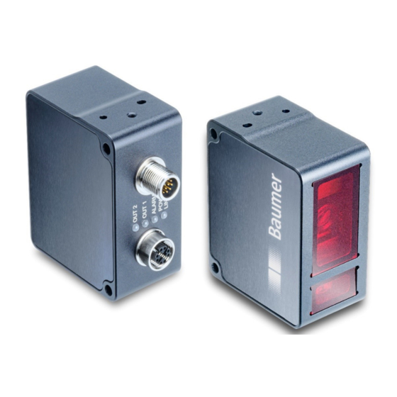
Description Baumer Description Sensor 3.1.1 Structure Ill. 2: OX200 – Structure Electrical connection Ethernet connection M12 12-pin, A-coded, male M12 8-pin, X-coded, female Sensor LEDs Front panel Operating Manual OX200 | V2... -
Page 11: Functionality
3. The reflected laser line is projected onto a surface camera in the sensor. 4. The sensor uses the camera image and stored calibration data to calculate the profile of a measurement object. Ill. 3: OX200 – Triangulation principle OX200 | V2 Operating Manual... -
Page 12: Ill. 4 Oxm200 - Functionality
Output of calibrated 2D point cloud for further external PC processing. Sensor parameterisation via intuitive web interface or freely available SDK (software devel- opment kit) with sample code. Synchronisation of profile image and belt speed for moving objects via integrated encoder input. Operating Manual OX200 | V2... -
Page 13: Ill. 6 Ox200 - Measurement Rate Limited By The Exposure Time
Depending on the measurement tool Measurement result output Response time Time Ill. 6: OX200 – Measurement rate limited by the exposure time Single shot Earliest possible mode (trigger) trigger pulse Exposure & read out Depending on: - Exposure time... -
Page 14: Reference Surfaces
Reference surfaces The purpose of the reference surfaces R1 to R3 presented below is to facilitate alignment of the sensor during mounting and commissioning. Ill. 8: OX200 – Reference surfaces Reference surface 1; positioned parallel Reference surface 2; positioned parallel to the side surface at a right angle to... -
Page 15: Field Of View Of The Sensor
The presence of measurement objects in this area can lead to incorrect measurement values. RP D: (0,0) : (0,0) – Ill. 9: OX200 – Field of view Positive alignment of the Z axis in the Positive alignment of the Z axis in the height mode distance mode... -
Page 16: Ill. 10 Ox200 - Transmission And Receiving Axes
Objects that should not be measured should be kept away from this area as they can interfere with the measurement and lead to incorrect measurement values. Ill. 10: OX200 – Transmission and receiving axes Operating Manual OX200 | V2... -
Page 17: Operating And Display Elements
The sensor contains an integrated web server for this purpose. The web interface is accessible through a web browser. For a detailed description of the web interface, the individual elements of the user interface and all required operating processes, see Web interface description [} 73]. Ill. 11: Web interface – Overview OX200 | V2 Operating Manual... -
Page 18: Sensor Leds
Description Baumer 3.2.2 Sensor LEDs Ill. 12: OX200 – LEDs on the sensor Denotation Colour Illuminated Blinking OUT 2 Yellow Switching output 2 active. Signal reserve of the detected object is close to the detection limit. OUT 1 Yellow Switching output 1 active. -
Page 19: Interfaces And Protocols
Profinet, EtherNet/IP, Modbus TCP, OPC UA and IO-Link. For the precise range of interfaces and protocols, please see the data sheet that is available for download at www.baumer.com/OX200. OX200 | V2 Operating Manual... -
Page 20: Industrial Ethernet [Oxm]
In the following, the individual data elements are described, which can be exchanged in different combinations in the shape of modules depending on the protocol used: Operating Manual OX200 | V2... - Page 21 (NaN) each and should therefore accordingly not be evaluated by the measurement ap- plication. Data element Direction Description Measured values Sensor > PLC Result data of the set measurement tools para- 1 ... 7 metrised via the web interface. OX200 | V2 Operating Manual...
-
Page 22: Profinet [Oxm]
Measurement rate (Hz) Float32 Time stamp (s) UInt32 Time stamp (µs) UInt32 Encoder value UInt16 Output 1 UInt8 Output 2 UInt8 Parameter: Name Sub-mod- Index Data type Byte off- Default Change- Visible value able Parameter setup UInt8 Operating Manual OX200 | V2... - Page 23 Input data sensor > PLC: Sub-module ID Data element Data type Measured value 1 Float32 Measured value 2 Float32 Measured value 3 Float32 Measured value 4 Float32 Measured value 5 Float32 Measured value 6 Float32 Measured value 7 Float32 OX200 | V2 Operating Manual...
-
Page 24: Ethernet/Ip [Oxm]
PLC parameterisation data > Sensor: Assembly Object (Class Code: 0x04), Instance 151 Byte Data element Data type Parameter setup UInt8 You can find an example of integration in EtherNet/IP: Integrating the sensor in the PLC [OXM] [} 58]. Operating Manual OX200 | V2... -
Page 25: Modbus Tcp [Oxm]
Reading or writing only part of the specified address ranges is not supported. The less significant words are saved at the lower address. Example: Value (UInt32): 0x12345678 Register address n: 0x5678 Register address n + 1: 0x1234 OX200 | V2 Operating Manual... - Page 26 PDU starting with zero. For this reason, input registers with the numbers 1-16 are addressed as 0-15. Address Data element Data type Access Offset Description 0 ... 32 Vendor info String[65] Read Manufacturer (33 bytes) name Operating Manual OX200 | V2...
- Page 27 Low 2 Bytes High 2 Bytes Measured value Float32 Measured value parametrised in advance on the web interface. Low 2 Bytes High 2 Bytes Measured value Float32 Measured value parametrised in advance on the web interface. OX200 | V2 Operating Manual...
- Page 28 (µs) the most recent measured values. Low 2 Bytes High 2 Bytes Encoder value UInt16 Encoder value of the connected encoder. Address Data element Data type Access Offset Description Active Parameter Setup Number. UInt8 Read (1 byte) Operating Manual OX200 | V2...
-
Page 29: Opc Ua [Oxm]
Of course, the sensor can also be configured using the software of other manufacturers and their controls. The steps must then be carried out correspondingly. Ill. 13: OPC UA – UaExpert Client – Surface Node Variable node (partial read/write) Variable node (characteristic or property) Method node (action with call) OX200 | V2 Operating Manual... - Page 30 Time stamp of the measurement (in s) TimeStampUSec Time stamp of the measurement (in µs) TimeSynchronised Time synchronisation active (yes/no) MeasurementValuesBlock Last 100 measurement results. In the case of new measure- ment results, the oldest measurement result disappears. Operating Manual OX200 | V2...
- Page 31 In the structure of the function tree, navigate to Root | Objects | Device Set | OX-Line | Lock | InitLock. c) In the context menu (right-click InitLock) select the option Call. d) In the Call InitLock on Lock window, confirm with Call. OX200 | V2 Operating Manual...
- Page 32 ParameterSetup | LoadParameterSetup. c) In the context menu (right-click LoadParameterSetup), select the option Call. d) Enter the desired parameter setup in the Call LoadParameterSetup on ParameterSetup window in the field Value. e) Confirm with Call. Operating Manual OX200 | V2...
-
Page 33: Io-Link [Oxm]
Acyclic data: The measurement values 1 to 7 parametrised via the web interface, the measurement rate of the sensor and all other available information (see IODD file) are transferred as acyclic data. For information regarding the commissioning of IO-Link, see Setting up IO-Link [OXM] [} 72]. OX200 | V2 Operating Manual... -
Page 34: Udp
If the sensor transmits a profile divided into several packets, the first frame provides the total num- ber of the related packets in the FrameCount field. Operating Manual OX200 | V2... -
Page 35: Ill. 15 Udp - Packet Framing Example
0x02 0x00 0x03 0x00 Dp+1 Ill. 15: UDP – Packet framing example Field Type Type dependant data Offset Unfragmented data ….. Fragmented data Dn+1 Do+1 Dp+1 ….. ….. ….. ….. Ill. 16: UDP – Body recomposition example OX200 | V2 Operating Manual... - Page 36 The content and order of the measurement results corres- MeasurementValue2 Float32 ponds to the order in the MeasurementValue3 Float32 measured value array. MeasurementValue4 Float32 MeasurementValue5 Float32 MeasurementValue6 Float32 MeasurementValue7 Float32 MeasurementRateHz Float32 TimestampSeconds UInt32 TimestampMicroSeconds UInt32 EncoderPosition UInt16 Operating Manual OX200 | V2...
- Page 37 Time is synced by NTP Bool Values are valid Bool Alarm Bool Quality UInt8 MeasurementRateHz Float32 TimestampSeconds UInt32 TimestampMicroSeconds UInt32 EncoderValue UInt16 ProfileLength UInt32 Number of profile points. Profile_x_coordinate_[0] UInt16 Profile_z_coordinate_[0] UInt16 Profile_x_coordinate_[n] 24+4*n UInt16 n = ProfileLength - 1 Profile_z_coordinate_[n] 24+4*n UInt16 OX200 | V2 Operating Manual...
- Page 38 Time is synced by NTP Bool Values are valid Bool Alarm Bool Quality UInt8 MeasurementRateHz Float32 TimestampSeconds UInt32 TimestampMicroSeconds UInt32 EncoderValue UInt16 ProfileLength UInt32 Number of profile points. Profile_x_coordinate_[0] UInt16 Profile_Intensity_[0] UInt16 Profile_x_coordinate_[n] 24+4*n UInt16 n = ProfileLength - 1 Profile_Intensity_[n] 24+4*n UInt16 Operating Manual OX200 | V2...
- Page 39 Bool Alarm Bool Quality UInt8 MeasurementRateHz Float32 TimestampSeconds UInt32 TimestampMicroSeconds UInt32 EncoderValue UInt16 ProfileLength UInt32 Number of profile points. Profile_x_coordinate_[0] UInt16 Profile_z_coordinate_[0] UInt16 Profile_Intensity_[0] UInt16 Profile_x_coordinate_[n] 24+6*n UInt16 n = ProfileLength - 1 Profile_z_coordinate_[n] 24+6*n UInt16 Profile_Intensity_[n] 24+6*n UInt16 OX200 | V2 Operating Manual...
-
Page 40: Sdk
2.4.0 or later (https://pypi.org). There are also several sample projects available that show how to use the SDK in C#, C++ and Python. These were created with Visual Studio 2017 and/or with Eclipse and a CDT plugin. Operating Manual OX200 | V2... - Page 41 Meta GetSensorInfo ParameterSetup LoadParameterSetup GetActiveSetup ConfigureStartupSetup GetStartupSetup GetParameterSetup GetNumberOfSetups StoreParameterSetup ReadAllSettings StartWriteSettings WriteSettingsBlock GetWriteSettingsBlockLimit WriteSettings FactoryReset ResetSettings ResetAllSettings Profiles GetProfileInfo GetProfile GetIntensityProfile ProfileConfiguration ConfigureResampling GetResamplingGridValue GetResamplingInfo ConfigureProfileFilter GetProfileFilter GetProfileFilterLimits ConfigureProfileAlgorithm GetProfileAlgorithm GetProfileAlgorithms GetProfileAlgorithm- ParamsLimits GetProfileAlgorithmParamsInfo OX200 | V2 Operating Manual...
- Page 42 Function ConfigureProfileAlgorithmPara- GetProfileAlgorithmParameters meters GetAxesInfo ConfigureZAxis GetZAxis RoleManagement Login DataAcquisition SetExposureTime GetExposureTime GetExposureTimeLimits GetExposureTimeResolution ConfigureResolution GetResolution GetResolutionInfo LaserPower ConfigureLaserPower GetLaserPower GetLaserPowerInfo GetLaserPowerLimits Trigger Trigger ConfigureTrigger GetTrigger GetTriggerLimits GetTriggerInfo Measurement GetMeasurement GetMeasurementInfo GetMeasurementValuesInfo Image GetImage GetImageInfo Operating Manual OX200 | V2...
-
Page 43: External Triggering
The recorded measurement value is maintained at all outputs. For the specification of input IN 1 (sync in), please see the data sheet that is available for down- load at www.baumer.com/OX200. The delay between the detection of a trigger and the start of a measurement is < 25 µs. -
Page 44: Ill. 18 Encoder - 2-Channel Operation
For safe operation, the maximum frequency of the encoder signal specified on the data sheet must not be exceeded. The sensor can process a minimum step width of 3. Channel A Channel B Step width 3 Ill. 18: Encoder – 2-channel operation Operating Manual OX200 | V2... -
Page 45: Transport And Storage
Keep away from the sun. Avoid mechanical agitation. Storage temperature: -10 ... +60 °C Ambient humidity: 20 ... 85 % When storing for longer than 3 months, regularly check the general state of all parts and the packaging. OX200 | V2 Operating Manual... -
Page 46: Mounting
The background should be dark, for example, matt black. Power is supplied via: ▪ the Ethernet connection (if a Power-over-Ethernet infrastructure is available), or ▪ the electrical connection (M12 12-pin, A-coded, male). Operating Manual OX200 | V2... -
Page 47: Mounting The Sensor
Mounting the sensor at the head end For head end mounting, the sensor features 2 dowel holes 3.05 × 4 mm (1 in the following fig- ure) and 1 tapped hole M4×6 (2). Ill. 20: OX200 – Head end mounting OX200 | V2 Operating Manual... -
Page 48: Electrical Installation
Device damage or unintended operation due to work on live parts. Work on live parts may lead to unintentional operation. a) Disconnect the power before carrying out any cable. b) Disconnect the power before connecting or disconnecting electrical connections. Operating Manual OX200 | V2... -
Page 49: Pin Assignment
OUT 2 IN 1 (sync in) Encoder B neg. Power / IO-Link L+ GND / IO-Link L- Pin 11 and pin 12 must also be connected if no IO-Link is used and OUT 1 should be used. OX200 | V2 Operating Manual... -
Page 50: Connecting The Sensor To Electricity
Use either a power supply unit or a PoE switch for the sensor power supply. The PoE switch must comply with the Standard IEEE 802.3af. Instruction: a) Ensure that the system is disconnected from power. b) Connect the sensor according to the pin assignment. Operating Manual OX200 | V2... -
Page 51: Commissioning
Start the web browser on your PC. b) Enter the IP address of the sensor in the address bar of the web browser. The factory setting for the IP address is 192.168.0.250. Ill. 24: Entering the IP address of the sensor OX200 | V2 Operating Manual... -
Page 52: Allocating An Ip Address To The Pc
IP address: in the range from 192.168.0.1 to 192.168.0.254. Select an IP address that is not allocated yet in your network. Subnet mask: 255.255.255.0. g) Click OK. Result: ü An IP address has been allocated to the PC. Operating Manual OX200 | V2... -
Page 53: Determining The Ip Address Of The Sensor
Allocating an IP address to the [} 52]). Make sure to allocate an IP address to the PC that is adjacent to the IP address of the sensor, e.g.: IP address of the PC: 192.168.0.251 IP address of the sensor: 192.168.0.250 OX200 | V2 Operating Manual... -
Page 54: Profinet: Integrating The Sensor In The Plc [Oxm]
Observe the general rules for wiring Industrial Ethernet. The maximum cable length is 100 m. Use shielded cables for data transfer. During assembly, make sure that the cable shield is correctly connected to the plug housing. Operating Manual OX200 | V2... -
Page 55: Connecting The Sensor To The Plc [Oxm]
The Profinet name of the sensor is set to the default value. ü Using a Profinet tool, the sensor can be allocated its Profinet name and, if required, its IP address. Connection to the PC is only possible after an IP address is allocated. OX200 | V2 Operating Manual... - Page 56 (product-specific driver) in the Siemens software. The GSD file describes the scope of the Profinet function in the device (e.g. the available modules) and is required for configuration. INFO The GSD file is available for download at www.baumer.com/OX200. To install the GSD file, proceed as follows: Instruction: a) Open the Siemens software.
-
Page 57: Integrating The Sensor Into The Plc Project [Oxm]
If necessary, adjust the input address range of the data in the PLC process image and the name. f) Compile the project (1) and then load it onto the PLC (2), by clicking the following button: For more information about the Profinet interface, see Profinet [OXM] [} 22]. OX200 | V2 Operating Manual... -
Page 58: Changing The Parameter Setup
Observe the general rules for wiring Industrial Ethernet. The maximum cable length is 100 m. Use shielded cables for data transfer. During assembly, make sure that the cable shield is correctly connected to the plug housing. Operating Manual OX200 | V2... -
Page 59: Connecting The Sensor To The Plc [Oxm]
ü The sensor has the IP address 0.0.0.0. ü The IP address can be allocated to the sensor using an EtherNet/IP tool. Connection to the PC is only possible after an IP address is allocated. OX200 | V2 Operating Manual... - Page 60 (product-specific driver) in the Rockwell software. The EDS file describes the scope of the Eth- erNet/IP function in the device (e.g. the available modules) and is required for configuration. INFO The EDS file is available for download at www.baumer.com/OX200. To install the EDS file, proceed as follows: Instruction: a) Open the Rockwell software.
- Page 61 Baumer Commissioning d) Select Register an EDS file(s) and click on Continue. e) Navigate to the EDS file to be installed and select Register a single file. Click on Con- tinue. OX200 | V2 Operating Manual...
- Page 62 Commissioning Baumer f) In the following dialogues, click on Continue. Result: ü The device description file (EDS) is now installed. Operating Manual OX200 | V2...
-
Page 63: Integrating The Sensor Into The Plc Project [Oxm]
Right click on Ethernet. c) Click on New Module. d) Enter OX in the Find line and double-click on the entry for OX-Line. e) In the General tab, enter the name and the IP address of the sensor. OX200 | V2 Operating Manual... - Page 64 In the Connection tab, set the desired cycle time (RPI) And click on OK. g) To compile and load the project into the PLC, select the menu Communications | Down- load. h) Click on Download. Operating Manual OX200 | V2...
- Page 65 Baumer Commissioning i) Click on Yes. Result: ü The sensor is now incorporated into the PLC project. For more information about the Ethernet interface, see Ethernet/IP [OXM] [} 24]. OX200 | V2 Operating Manual...
-
Page 66: Reading/Changing Parameter Setup Via Parameter 151
Under Controller Tags | Edit Tags, create the variable ConfigData_Value_SINT with the data type SINT. d) Create the following program modules: e) To fill in the content of the message, proceed as follows. In the Destination Elementfield, select ConfigData_Value_SINT. Operating Manual OX200 | V2... - Page 67 Under Controller Tags | Edit Tags, create the variable Activate_Write_ConfigData with data type BOOL. c) Under Controller Tags | Edit Tags, create the variable ConfigData_Value_SINT with the data type SINT. d) Create the following program modules: OX200 | V2 Operating Manual...
- Page 68 ConfigData_Value_SINT. f) Go online (connection to PLC established). g) Under Controller Tags, enter the desired value for Parameter 151. h) Click on Activate_Write_ConfigData and then press Ctrl + T. Result: ü Parameter 151 is written. Operating Manual OX200 | V2...
-
Page 69: Additional Information About Accessing Cyclic Process Data
ü Using the COP instruction specified, the bytes OX200:I.Data[7] to OX200:I.Data[10] are copied to the variable Input 1. On an OX200, the process data bytes 7 to 10 correspond to Measured value 1. The data type for Measured value 1 is REAL. OX200 | V2... -
Page 70: Additional Notes About Ethernet/Ip Objects
The Modbus TCP server (Modbus TCP slave) integrated in the sensor can be addressed using the following parameters: TCP port no.: 502 Modbus TCP Unit Identifier: 1 For more information about the Modbus interface, see Modbus TCP [OXM] [} 25]. Operating Manual OX200 | V2... -
Page 71: Opc Ua: Adding Sensor In Uaexpert Client [Oxm]
In the Enter URL window, enter the IP address of the sensor. f) Confirm with OK. ü The sensor appears in the Add Server window under Custom Discovery. g) Confirm with OK. ü The sensor appears in the Project window under Project | Servers. OX200 | V2 Operating Manual... -
Page 72: Setting Up Io-Link [Oxm]
OUT 1 / IO-Link C/Q Encoder B OUT 2 IN 1 (sync in) Encoder B neg. Power / IO-Link L+ GND / IO-Link L- For more information about the IO-Link interface, see IO-Link [OXM] [} 33]. Operating Manual OX200 | V2... -
Page 73: Web Interface Description
"sees", so you can use this information to precisely adjust the sensor to the given conditions. Description of the user interface Ill. 26: Web interface – user interface Header area Menu bar Parametrisation area Footer area Visualisation area Measurement Results window OX200 | V2 Operating Manual... -
Page 74: Header Area
Message that a change has not been stored yet. Button for requesting support via e-mail. Display of sensor type and serial number. Link to the Baumer website. Selection of the language of the user interface. Operating Manual OX200 | V2... -
Page 75: Menu Bar
When importing, you can select whether these are imported. Device Configuration Setting the interface-specific properties (Ethernet configura- tion, active process interfaces). Condition Monitoring Display of diagnostic data, such as operating time, temperat- ure and operating voltage. OX200 | V2 Operating Manual... -
Page 76: Measurement Results Window
In the parametrisation area, depending on the selected menu item within the Parametrization mode, you can set various parameters (see Global Parametrization mode [} 79], Measurement Tools Parametrization mode [OXM] [} 96], Outputs Parametrization mode [OXM] [} 100] Save Parameter-Setups mode [} 105]). Operating Manual OX200 | V2... -
Page 77: Web Interface Operation
Selection of the signal quality and the visualised switching states via a drop-down list: ▪ Signal quality: Green: valid signal Yellow: weak signal Red: no signal (no valid measured value) ▪ Switching out: Yellow: switching output is active Grey: switching output is inactive OX200 | V2 Operating Manual... -
Page 78: Saving Measured Data As A Csv File
In the visualisation area click the button II Pause. ü The currently displayed measured data are frozen. b) Click the diskette symbol in the visualisation area. c) The file is saved in the .csv format. Operating Manual OX200 | V2... -
Page 79: Global Parametrization Mode
To change the view in the visualisation area, proceed as fol- lows: Instruction: w Select the desired view in the drop-down menu on the top left of the visualisation area. You can choose from the following views: OX200 | V2 Operating Manual... -
Page 80: Ill. 29 Web Interface - Parametrisation Mode - Result Over Time & Profile View
In the visualisation area click the button II Pause. ü The currently displayed measured data are frozen. b) Click the diskette symbol in the visualisation area to the right of the profile graph. c) The file is saved in the .csv format. Operating Manual OX200 | V2... -
Page 81: Ill. 30 Web Interface - Parametrisation Mode - Profile & Camera Picture View
The lower button can be used to show an overlay indicating a cut along a select camera column. The overlay indicates the intensity of the column. The active column can be freely se- lected by the grey slider underneath the camera image. OX200 | V2 Operating Manual... -
Page 82: Ill. 31 Web Interface - Parametrisation Mode - Intensity & Camera Picture View
In the visualisation area click the button II Pause. ü The currently displayed measured data are frozen. b) Click the diskette symbol in the visualisation area to the right of the camera image. c) The file is saved in the .png format. Operating Manual OX200 | V2... -
Page 83: Ill. 32 Web Interface - Parametrisation Mode - Profile & Intensity View
Result over Time & Profile view. The bottom diagram shows the summarised pixel values along a column. This diagram corres- ponds to the top diagram in the Intensity & Camera Picture view. OX200 | V2 Operating Manual... -
Page 84: Ill. 33 Web Interface - Parametrisation Mode - Profile View
Ill. 33: Web interface – Parametrisation mode – Profile view The diagram in this view shows the profile points of the object. This diagram corresponds to the bottom diagram in the Result over Time & Profile view. Operating Manual OX200 | V2... -
Page 85: Adjusting The Internal Resolution
Place the object to be measured in the field of view of the sensor. d) Click the Optimize button. Result: ü The sensor automatically adjusts the exposure time (once). INFO In Expert Mode, you have the additional option of manually adjusting the exposure time in the entire range. OX200 | V2 Operating Manual... -
Page 86: Adjusting The Laser Power
In the menu, select the Parametrization | Global Parametrization mode. b) In the Global Parameters window, proceed to Data Acquisition | Laser Power Selection. c) In the drop-down list next to Laser Power Level, select the desired level of the laser power. Operating Manual OX200 | V2... -
Page 87: Calculating The Surface Profile
With profile smoothing, profile points are averaged with the respective adjacent profile points. This can reduce spatial noise, which can be caused, for example, by the structure of the surface or by speckle patterns. You can set the profile smoothing within the Profile Computation area via Filter. OX200 | V2 Operating Manual... -
Page 88: Trigger Mode Setting
As soon as the IN 1 (sync in) input is set to high, all output functions are frozen in their last state until the next measurement. For the specification of input IN 1 (sync in), please see the data sheet that is available for download at www.baumer.com/OX200. Encoder: Use the encoder input for synchronisation with an external movement, such as a conveyor belt. -
Page 89: Aligning The Sensor (Height And Distance Mode)
In distance mode (sensor space), the zero point of the Z axis is at the front of the sensor , see also Field of view of the sensor [} 15]). The positive direction of the Z axis points away from the sensor. OX200 | V2 Operating Manual... -
Page 90: Mounting Assistant
Mounting Assistant INFO Baumer recommends mounting the sensor at a right angle to the reference surface of the meas- uring object. The Mounting Assistant function of the web interface supports you with this. If 90° mounting is not possible, the Flex Mount function allows compensation of a mounting angle up to ±30°... -
Page 91: Flex Mount: Compensating Mounting Angles
By angling the sensor, the two sections of the meas- urement field (measurement field width left (area A) and measurement field width right (area B)) are no longer the same size. Ill. 35: OX200 – Reference point for angled mounting OX200 | V2 Operating Manual... -
Page 92: Ill. 36 Ox200 - Tilt Angle And Distance To The Reference Surface With Angled Mounting
Ill. 36: OX200 – Tilt angle and distance to the reference surface with angled mounting To activate the Flex Mount function, proceed as follows: Condition: ð... -
Page 93: Ill. 37 Ox200 - Minimum Length Of The Reference Surface L
You can then deduct the thickness via the web interface (see Flex Mount: Moving the reference surface [} 94]). Ill. 37: OX200 – Minimum length of the reference surface L R, min OX200 | V2 Operating Manual... -
Page 94: Flex Mount: Moving The Reference Surface
Example: When using the Delta Height function within Parametrization | Measurement Tools, the taught-in reference surface impairs the measurement result. Ill. 38: OX200 – Flex Mount – Moving the reference surface To move the reference surface, proceed as follows: Instruction: a) In the menu, select the Parametrization | Global Parametrization mode. -
Page 95: Resetting Flex Mount
The Region of Interest Limits function in the Measurement Tools Parametrization mode is available for masking disruptive reflexes or undesired objects. You can set individual evaluation range limits for each stored measurement tool. OX200 | V2 Operating Manual... -
Page 96: Measurement Tools Parametrization Mode [Oxm]
Blind regions (shown in grey on the web interface) are the regions outside the ROI. Profile points and measurement values inside the blind region are ignored in the evaluation. You can freely select the blind regions (on the web interface with the help of the sliders or the input fields). Operating Manual OX200 | V2... -
Page 97: Setting The Position Tracking (Roi Tracking) [Oxm]
If the position of the edge changes, the position of the ROI is dynamically tracked. find lock Edge position & Z Ill. 40: OX200 – Position tracking (ROI tracking) To set the position tracking, proceed as follows: Instruction: a) In the menu, select the Parametrization | Measurement Tools Parametrization mode. -
Page 98: Setting Background Tracking [Oxm]
You can select a line defined previously in a line / angle measuring tool as the background source. If the position of the background line changes, the position of the ROI is tracked dynam- ically. Ill. 41: OX200 – Background tracking To set background tracking, proceed as follows: Instruction: a) In the menu, select the Parametrization | Measurement Tools Parametrization mode. -
Page 99: Setting The Temporal Filter [Oxm]
In the menu, select the Parametrization | Measurement Tools Parametrization mode. b) In the Measurement Tools window, go to the desired measurement tool and select Invalid Value Handling. c) Enter the desired holding time for the invalid measured value. OX200 | V2 Operating Manual... -
Page 100: Outputs Parametrization Mode [Oxm]
With Polarity, you can determine how the switching outputs behave with respect to the output level. In the web interface the region where the switching outputs are set to high is shown in grey. – – Active low Active high – – Operating Manual OX200 | V2... - Page 101 Processing of the point cloud is easier for most algorithms if the profile points are uniformly distributed along the X axis. Here, you can select how the profile points are output: ▪ Raw (not equidistant) ▪ Interpolated (equidistant) OX200 | V2 Operating Manual...
-
Page 102: Setting The Hysteresis [Oxm]
The hysteresis is situated outside the switching points (window mode) or points towards larger measurement values (point mode). With a positive hysteresis, the minimum distance between the switching points is 0. Ill. 42: OX200 – negative hysteresis Ill. 43: OX200 – positive hysteresis Operating Manual... - Page 103 Ill. 44: Behaviour of the switching output in point mode (positive hysteresis) Example: Switching point P1 Negative hys- teresis Hysteresis High Active low level Level Ill. 45: Behaviour of the switching output in point mode (negative hysteresis) OX200 | V2 Operating Manual...
- Page 104 Window Hysteresis Switching point P2 High Level Active high level Ill. 47: Behaviour of the switching output in window mode (negative hysteresis) Polarity With Polarity, you can invert the level with Active High or Active Low. Operating Manual OX200 | V2...
-
Page 105: Save Parameter-Setups Mode
Individual parameter setups can be saved, load or deleted. They are referenced via the process interfaces through use of a unique number, which can also be displayed in the Web in- terface. Ill. 48: Web interface – Save parameter setup mode OX200 | V2 Operating Manual... -
Page 106: Device Configuration Mode
If DHCP is deactivated, the IP address is retained. Time Synchronization The time stamps of the measurement results are set according to the synchronisation. UTC is the time basis. Note: The daylight savings time function is not supported! Operating Manual OX200 | V2... - Page 107 − Security Activation/deactivation of Password Protection. − Factory Reset Resetting the sensor to factory settings. − Settings Reset Resetting the sensor settings. The IP address is not reset in this process. OX200 | V2 Operating Manual...
-
Page 108: Preventive Maintenance
Do not use scouring agents, solvents or other aggressive cleaning agents. c) Do not use jets of liquid for cleaning, for example a high-pressure cleaner. d) Do not scrape off soiling with sharp-edged items. Interior clean- No interior cleaning of the sensor is required. Operating Manual OX200 | V2... -
Page 109: Troubleshooting
Do not dispose of electrical and electronic equipment in household waste. The product contains valuable raw materials for recycling, which is why the old product must be returned to an authorised collecting point for correct disposal/recycling. For further information see www.baumer.com. 11.4 Accessories You can find accessories at the website at: https://www.baumer.com/OX200... -
Page 110: Technical Data
Technical data The technical data for your sensor can be found in the data sheet that is available for download at www.baumer.com/OX200. 12.1 Dimensional drawing LASER ø 3,05 ±0,05 3,05 ±0,05 Ill. 50: OX200 – Dimensional drawing Operating Manual OX200 | V2... - Page 111 Ill. 35 OX200 – Reference point for angled mounting .................. 91 Ill. 36 OX200 – Tilt angle and distance to the reference surface with angled mounting....... 92 Ill. 37 OX200 – Minimum length of the reference surface L ..............93 R, min Ill.
- Page 112 List of illustrations Baumer Ill. 39 Web interface – Measurement Tools Parametrization mode.............. 96 Ill. 40 OX200 – Position tracking (ROI tracking)................... 97 Ill. 41 OX200 – Background tracking......................98 Ill. 42 OX200 – negative hysteresis......................102 Ill. 43 OX200 – positive hysteresis ....................... 102 Ill.
- Page 114 Baumer Worldwide Belgium Brazil Canada Baumer SA/NV Baumer do Brasil Ltda Baumer Inc. BE-2260 Westerlo BR-13208-120 Jundiaí, São Paulo CA-Burlington, ON L7M 4B9 Phone +32 14 57 462 0 Phone +55 11 4523-5120 Phone +1 905 335 8444 China France Denmark Baumer (China) Co., Ltd.
Need help?
Do you have a question about the OX200 and is the answer not in the manual?
Questions and answers