Table of Contents
Advertisement
Quick Links
Advertisement
Chapters
Table of Contents

Related Manuals for Baumer OXM200-R05A.001


Summary of Contents for Baumer OXM200-R05A.001
- Page 1 Operating Manual OX200 EN-US Smart Profile sensors...
-
Page 2: Table Of Contents
List of contents Baumer List of contents 1 About this document........................... Purpose .............................. Warnings in this manual ........................Labels ..............................Liability limitation..........................Scope of delivery ..........................Name plate ............................2 Safety................................Intended use ............................Personnel requirements........................General safety instructions ......................... - Page 3 Baumer List of contents 7 Commissioning............................59 Connecting the sensor to the PC......................59 7.1.1 Allocating an IP address to the PC ..................60 7.1.2 Tracking the sensor's IP address..................61 Profinet: Integrating the sensor in the PLC [OXM]................62 7.2.1...
- Page 4 List of contents Baumer 9.3.2 Setting background tracking [OXM] ..................106 9.3.3 Setting the Temporal Filter [OXM] ..................107 9.3.4 Processing an invalid measured value [OXM] ..............107 Outputs Parametrization mode [OXM]....................108 9.4.1 Setting the hysteresis [OXM] ....................110 Mode Save Parameter-Setups ......................113 Mode Device Configuration ........................
-
Page 5: About This Document
In addition, the local occupational health and safety regulations and general safety regulations apply. The illustrations in this manual are examples only. Deviations are at the discretion of Baumer at all times. Warnings in this manual Warnings draw attention to potential personal injury or material damage. -
Page 6: Labels
Scope of delivery The scope of delivery includes: 1 x sensor 1 x Quick start guide 1 x General information leaflet In addition, you can find the following information in digital format at www.baumer.com/OX200: Operating manual Data sheet 3D CAD drawing Quickstart Dimensional drawing Connection diagram &... -
Page 7: Name Plate
Baumer About this document Name plate Ill. 1: Name plate on the sensor Type code, MAC address, serial num- Item number, production date Pin pictogram Pin assignment Labels QR code (Baumer website) V3 | OX200 Operating Manual... -
Page 8: Safety
Safety Baumer Safety Intended use The sensor is used to measure surface profiles for the following purposes: Check and inspect: ▪ Checking and inspection of object geometries, such as height measurement, inspection of surfaces, etc. ▪ Inline quality control of object geometries. -
Page 9: General Safety Instructions
Baumer Safety General safety instructions Assembly, mounting, and calibration of the sensor may only be performed by a specialist. Only use the fasteners and fastener accessories intended for the sensor for mounting. Outputs not in use must not be wired. Unused wires of cable outputs must be insulated. -
Page 10: Description
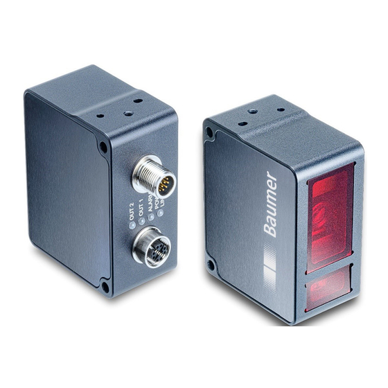
Description Baumer Description Sensor 3.1.1 Structure Ill. 2: OX200 – Structure Electrical connection Ethernet connection M12 12-pin, A-coded, male M12 8-pin, X-coded, female Sensor LEDs Front panel Operating Manual OX200 | V3... -
Page 11: Functionality
Baumer Description 3.1.2 Functionality The sensor measures the surface profile of an object along the projected laser line. The mea- sured surface profile can be retrieved by the user – either via the integrated web server, the UDP interface or the SDK (software development kit). Sensors in the OXM version have addi- tional integrated functions (tools) that allow carrying out geometric measurements on the profile (such as width, height, circle diameter or angle). -
Page 12: Ill. 4 Oxm200 - Functionality
Description Baumer Functionality of the OXM version OXM200 7 measured values Ill. 4: OXM200 – Functionality The sensor is equipped with smart measurement functions (tools) as well as integrated im- age processing and delivers precise results in physical units such as mm or degrees. -
Page 13: Ill. 6 Ox200 - Measurement Rate Limited By The Exposure Time
Baumer Description Measurement frequency, measurement repeat time and response time A complete measurement cycle of the sensor consists of the following steps: 1. Exposure and read out 2. Calculation 3. Output of the measured values To increase the measurement speed, process steps are executed in parallel. The illustration be- low shows two scenarios: measurement rate limited by exposure time (Fig.1) and measurement... -
Page 14: Reference Surfaces
Description Baumer The time between two exposure periods is called the measurement repeat time, which can be converted into a measurement frequency. The calculated measurement frequency indicates how many measured values the sensor can output per second. Formula for calculating the measurement frequency: ▪... -
Page 15: Measurement Field Of The Sensor
Baumer Description 3.1.4 Measurement field of the sensor The following illustration shows the measurement field of the sensor. The sensor can be oper- ated in both height mode (object space) and distance mode (sensor space) (see also Aligning the sensor (height and distance mode) [} 97]). -
Page 16: Ill. 10 Ox200 - Transmission And Receiving Axes
Description Baumer Transmission and receiving axis The transmission and receiving axes can lie in the areas shown in blue in the figures below. The exact axes depend on the position of the object. Objects that should not be measured should be kept away from this area as they can interfere with the measurement and lead to incorrect mea- sured values. -
Page 17: Operating And Display Elements
Baumer Description Operating and display elements 3.2.1 Web interface The sensor features a web interface enabling sensor parameterization and data visualization. For doing so, the sensor integrates a web server. Web interface access is via web browser. For a detailed description of the web interface, the individual elements of the user interface and... -
Page 18: Sensor Leds
Description Baumer 3.2.2 Sensor LEDs Ill. 12: OX200 – LEDs on the sensor Denotation Colour Illuminated Flashing OUT 2 Yellow Switching output 2 active. Signal reserve of the detected object is close to the detection limit. OUT 1 Yellow Switching output 1 active. -
Page 19: Interfaces And Protocols
Profinet, EtherNet/IP, Modbus TCP, OPC UA and IO-Link. For the precise range of interfaces and protocols, please see the data sheet that is available for download at www.baumer.com/OX200. V3 | OX200 Operating Manual... -
Page 20: Industrial Ethernet [Oxm]
Description Baumer 3.3.1 Industrial Ethernet [OXM] Industrial Ethernet protocols (e.g. Profinet) enable the communication between the sensor and a PLC. In general, the following data can be transferred: General control and status data (measuring rate, time stamp, status of outputs, etc.) - Page 21 Baumer Description Module: Con- In the control and status module you have access to: trol and sta- Data element Direction Description Parameter setup PLC > sensor Currently used parameter setup 1 to 3. Change only possible in the parametrisation mode.
-
Page 22: Profinet [Oxm]
Description Baumer 3.3.2 Profinet [OXM] Profinet (Process Field Network) is an open Industrial Ethernet standard from PI (Profibus and Profinet International) and is based on existing IT standards (such as UDP, for example). For information regarding the commissioning of Profinet, see... - Page 23 Baumer Description Module: Re- Module ID: 4 sult data Preselected in slot 2 Input data sensor > PLC: Sub-module ID Data element Data type Measured value 1 Float32 Measured value 2 Float32 Measured value 3 Float32 Measured value 4 Float32...
-
Page 24: Ethernet/Ip [Oxm]
Description Baumer 3.3.3 EtherNet/IP [OXM] EtherNet/IP is a TCP/IP- and UDP/IP-based network protocol that is widely used in automation technology. As with other protocols developed further by ODVA, it uses the Common Industrial Protocol (CIP) in the application layer. Connectivity... - Page 25 Baumer Description Mapping the sensor functions on the CIP assembly objects The following tables give an overview of the arrangement of the sensor functions (data ele- ments) in the individual assembly objects. The assembly objects can be accessed via either an implicit or an explicit connection.
- Page 26 Description Baumer Sensor input data > PLC: Assembly Object (Class Code: 0x04), Instance 101 Byte Data element Data type Parametrisation mode UInt8 Time synchronization UInt8 Valid values UInt8 Alarm state UInt8 Quality status UInt8 Output 1 UInt8 Output 2 UInt8 7 ... 10...
- Page 27 Baumer Description Sensor input data > PLC: Assembly Object (Class Code: 0x04), Instance 102 Byte Data element Data type Parametrisation mode UInt8 Time synchronization UInt8 Valid values UInt8 Alarm state UInt8 Quality status UInt8 Output 1 UInt8 Output 2 UInt8 7 ... 8...
- Page 28 Description Baumer Sensor input data > PLC: Assembly Object (Class Code: 0x04), Instance 103 Byte Data element Data type Parametrisation mode UInt8 Time synchronization UInt8 Valid values UInt8 Alarm state UInt8 Quality status UInt8 Output 1 UInt8 Output 2 UInt8 7 ... 8...
- Page 29 Baumer Description PLC parameterization data > Sensor: Assembly Object (Class Code: 0x04), Instance 110 Byte Data element Data type Laser state OUT: UInt8 0: Laser off 1: Laser on 2 ...255: reserved Parameter Ctrl OUT: UInt8 Bit 0: Request Bit 1: 1 = Write / 0 = Read 2 ...255: reserved...
-
Page 30: Ill. 13 Load New Parameter Setup (Error)
Description Baumer Byte Data element Data type 2 ... 5 Parameter value IN 4 bytes, data type depending on the applied parameter, see table Func- Result depending on parameterization tion ID state IN (see above): Done = 1 -> requested value Error = 1 -> Error Code... -
Page 31: Ill. 14 Load New Parameter Setup (Success)
Baumer Description Ctrl.Request (OUT) Ctrl.Write (OUT) Parameter (OUT) 0: ParameterSetup Parameter Value (OUT) <ParameterSetup No.> State.Done (IN) State.Error (IN) State.Busy (IN) Value (IN) Ill. 14: Load new Parameter Setup (success) The diagram above shows an example timeline for loading of new parameter setup without er-... -
Page 32: Modbus Tcp [Oxm]
Description Baumer 3.3.4 Modbus TCP [OXM] Modbus TCP is a protocol with a long history that is already supported by many programmable logic controllers as delivered or can be retrofitted using a software module. For PC-based sys- tems, libraries for different programming languages are available. The standard is freely avail- able on the website of the Modbus organisation. - Page 33 Baumer Description Holding Reg- The following table provides an overview of the Index Commands Holding Registers. These isters can be reached with functions 03/06/16. Address Data element Data type Access Description Request parametrisation UInt16 Write Request parametrisation (1 Regis- mode.
- Page 34 Description Baumer Data Address Data element type Access Offset Description 200 ... 223 All Measure- Read (24 Regis- ment Values ter) Status UInt16 Status Bit 0 Parametrisation mode is ac- tive. Bit 1 Time is synchronised with NTP server. Bit 2 Valid values (measured values allow for interpretation).
- Page 35 Baumer Description Data Address Data element type Access Offset Description High 2 Bytes Measured Float32 Measured value parametrised in ad- value 7 vance on the web interface. Low 2 Bytes High 2 Bytes Measurement Float32 Measurement rate rate Low 2 Bytes High 2 Bytes Time stamp (s) UInt32 Value of the time stamp (s) of the most recent measured values.
- Page 36 Description Baumer Data Address Data element type Access Offset Description No signal. Output UInt8 Outputs Bit 0 Status of binary output 1. Bit 1 Status of binary output 2. Measured Int16 Measured value parametrised in ad- value 1 vance on the web interface.
-
Page 37: Opc Ua [Oxm]
Baumer Description 3.3.5 OPC UA [OXM] OPC UA (Open Platform Communications United Architecture) is an open interface standard, which was developed specifically for the requirements of automation technology. An increasing number of controls and systems already support the required client functionality. Various soft- ware libraries are available for PC-based systems. - Page 38 Description Baumer Identification The following table provides an overview of the Identification folder in the function tree. OPC UA command Sensor command ProductId Item/order number of the sensor Lock The following table provides an overview of the Lock folder in the function tree.
- Page 39 Baumer Description MethodSet The following table provides an overview of the MethodSet folder in the function tree. OPC UA command Sensor command LoadParameterSetup Load stored parameter setup 1-3. The value 1-3 must be given. ParameterSet The following table provides an overview of the ParameterSet folder in the function tree.
- Page 40 Description Baumer Reading out the measured value a) Open the function tree of the sensor in the Address Space window. b) In the structure of the function tree, navigate to Root | Objects | Device Set | OX-Line | Measurement.
-
Page 41: Io-Link
Baumer Description 3.3.6 IO-Link The sensor supports IO-Link communication for transfer of cyclic process data and status infor- mation. The device supports COM 3 transmission rate in line with IO-Link specification. You can either use the setup parameters stored in the sensor or the web interface-programmed... -
Page 42: Udp
Description Baumer 3.3.7 The sensor is equipped with a UDP interface, which makes it possible to stream measured val- ues as well as profile and intensity data from the sensor. UDP (User Datagram Protocol) is a connectionless and unsecured protocol that is based on the Internet Protocol (IP) network pro- tocol. -
Page 43: Ill. 17 Udp - Packet Framing Example
Baumer Description UDP header The following table provides an overview of the UDP header. Field name Offset Data type Description BlockId UInt32 Incremented with each UDP packet block sent (profiles can be sent in sev- eral UDP packets in one block). - Page 44 Description Baumer UDP body The following table provides an overview of the UDP body. The content of the UDP body depends on the MessageType field. MessageType: Measured values Field name Offset Value Data type Description MessageType UInt8 0 = Measured values 1 = Z profile 2 = I profile...
- Page 45 Baumer Description MessageType: Z profile Field name Offset Value Data type Description MessageType UInt8 0 = Measured values 1 = Z profile 2 = I profile 3 = Z-I profile ConfigMode active Bool Time is synced by NTP Bool Values are valid Bool Alarm Bool Quality UInt8 MeasurementRateHz...
- Page 46 Description Baumer MessageType: I profile Field name Offset Value Data type Description MessageType UInt8 0 = Measured values 1 = Z profile 2 = I profile 3 = Z-I profile ConfigMode active Bool Time is synced by NTP Bool Values are valid Bool Alarm Bool Quality UInt8 MeasurementRateHz...
- Page 47 Baumer Description MessageType: Z I profile Field name Offset Value Data type Description MessageType UInt8 0 = Measured values 1 = Z profile 2 = I profile 3 = Z-I profile ConfigMode active Bool Time is synced by NTP Bool Values are valid Bool Alarm Bool Quality UInt8...
-
Page 48: Sdk
Description Baumer 3.3.8 An SDK (software development kit) is available for the sensor. The SDK allows you to conve- niently integrate the sensor into your own applications. However, compared to the web inter- face, the SDK does not provide all parametrisation options for the sensor, e.g. it is not possible to parametrise the smart functions (measurement tools) with the SDK. - Page 49 Baumer Description Scope of functions The following table provides an overview of the commands and functions supported by the SDK: Function FieldOfView GetFieldOfViewInfo GetFieldOfViewLimits ConfigureFieldOfView GetFieldOfView ConfigureFieldOfViewDistance GetFieldOfViewDistance Interfaces ConfigureNetwork GetNetworkConfiguration ConfigureProcessInterfaces GetProcessInterfaces GetProcessInterfacesInfo GetUdpStreamingInfo ConfigureUdpStreams GetActiveUdpStreams GetNumberOfTimeServers ConfigureTimeServer GetTimeServerConfiguration...
- Page 50 Description Baumer Function ConfigureProfileAlgorithmPara- GetProfileAlgorithmParameters meters GetAxesInfo ConfigureZAxis GetZAxis RoleManagement Login DataAcquisition SetExposureTime GetExposureTime GetExposureTimeLimits GetExposureTimeResolution ConfigureResolution GetResolution GetResolutionInfo LaserPower ConfigureLaserPower GetLaserPower GetLaserPowerInfo GetLaserPowerLimits Trigger Trigger ConfigureTrigger GetTrigger GetTriggerLimits GetTriggerInfo Measurement GetMeasurement GetMeasurementInfo GetMeasurementValuesInfo Image GetImage GetImageInfo Operating Manual OX200 | V3...
-
Page 51: External Triggering
The recorded measured value is maintained at all outputs. For the specifi- cation of input IN 1 (sync in), please see the data sheet that is available for download at www.baumer.com/OX200. The delay between the detection of a trigger and the start of a mea- surement is < 25 µs. -
Page 52: Ill. 20 Encoder - 2-Channel Operation
Description Baumer Encoder If an encoder is connected to the sensor, the measured value recording can be triggered by the encoder steps. INFO If the encoder inputs are not connected and not connected to GND, the sensitive encoder input may interpret and count ambient noise as steps. This does not affect the performance of the sensor. -
Page 53: Transport And Storage
Baumer Transport and storage Transport and storage Transport NOTICE Material damage due to improper transport. a) Practice the greatest diligence when unloading the delivery packages and when transporting them within the company. b) Note the information and symbols on the packaging. -
Page 54: Installation
Installation Baumer Installation General information for mounting Recommended installation: The sensor's reference level R2 aligned in parallel towards the surface to be measured If required, the optimal alignment of the sensor can be graphically supported by the mount- ing assistant in the web interface. -
Page 55: Mounting The Sensor
Baumer Installation Mounting the sensor Mounting the sensor on the side Ill. 21: OX200 – Side mounting Condition: ð Screws M4×40 (2). ð Matching washers (preferably toothed to penetrate the anodised layer of the sensor hous- ing). Instruction: w Screw the sensor in place. -
Page 56: Electrical Installation
Electrical installation Baumer Electrical installation NOTICE Device damage due to faulty power supply. The device can be damaged due to faulty power supply. a) Operate the device only with protected low voltage and safe electrical isolation of protection class III. -
Page 57: Ill. 24 Oxm200 - Electrical Connection, M12 12-Pin, A-Coded, Male
Baumer Electrical installation Electrical connection for the OXM version Ill. 24: OXM200 – Electrical connection, M12 12-pin, A-coded, male Power (18 ... 30 VDC) / GND / IO-Link P24 (2L+) IO-Link N24 (2M) Encoder A Analog Out Encoder A neg. OUT 1 / IO-Link C/Q Encoder B... -
Page 58: Connecting The Sensor To Electricity
Electrical installation Baumer Connecting the sensor to electricity NOTICE For sensor supply use either a power unit or a PoE switch. PoE switch must be compliant to Standard IEEE 802.3af. Instruction: a) Ensure that the system is disconnected from power. b) Connect the sensor according to the pin assignment. -
Page 59: Commissioning
Baumer Commissioning Commissioning Connecting the sensor to the PC INFO Prerequisite for using the web interface is a web browser on your PC, Mozilla Firefox from Ver- sion 69 or Google Chrome from Version 77. Internet Explorer is not supported in any version and cannot be used for connection to the sen- sor. -
Page 60: Allocating An Ip Address To The Pc
Commissioning Baumer 7.1.1 Allocating an IP address to the PC NOTICE Network errors due to multiple allocations of IP addresses. a) Make sure that each IP address within the network is unique and not already allocated. The following section describes how to allocate a unique IP address to the PC. The prerequisite for this is that the IP address of the sensor has not been changed. -
Page 61: Tracking The Sensor's Ip Address
Baumer Commissioning Result: ü An IP address has been allocated to the PC. 7.1.2 Tracking the sensor's IP address Below is a description of how to determine the IP address of the sensor. This is required if the IP address was assigned via DHCP or the statically set IP address is no longer available. In general, there are 2 options for determining the IP address. -
Page 62: Profinet: Integrating The Sensor In The Plc [Oxm]
Commissioning Baumer Profinet: Integrating the sensor in the PLC [OXM] INFO The examples in this section refer to a Siemens control and the associated software TIA Portal/ Step7. The illustrations in this document were created with TIA Portal/Step7 v13 SP2. Of course, the sensor can also be configured using the software of other manufacturers and their controls. -
Page 63: Connecting The Sensor To The Plc [Oxm]
Baumer Commissioning 7.2.2 Connecting the sensor to the PLC [OXM] To connect the sensor to the PLC, proceed as follows: Activate Profinet on the sensor Profinet is deactivated as standard in the factory settings of the sensor. After connecting the sensor, go to the Siemens software (Accessible Devices dialogue) and check whether the sensor is visible. - Page 64 (product-specific driver) in the Siemens software. The GSD file describes the scope of the Profinet function in the device (e.g. the available modules) and is required for configuration. INFO The GSD file is available for download at www.baumer.com/OX200. To install the GSD file, proceed as follows: a) Open the Siemens software.
-
Page 65: Integrating The Sensor Into The Plc Project [Oxm]
Baumer Commissioning 7.2.3 Integrating the sensor into the PLC project [OXM] After the GSD file has been installed, the sensor can be used in the PLC project. PLC configu- ration usually takes place independently of the actual connection in the network. Proceed as fol-... -
Page 66: Changing The Parameter Setup
Commissioning Baumer 7.2.4 Changing the parameter setup You can change the parameter settings via the acyclic communication path. Most PLCs offer in- tegrated functions for this. Use the functions RDREC or WDREC to read or write acyclic data for a Siemens PLC and when working via the TIA Portal. -
Page 67: Connecting The Sensor To The Plc [Oxm]
Baumer Commissioning 7.3.2 Connecting the sensor to the PLC [OXM] To connect the sensor to the PLC, proceed as follows: Activating EtherNet/IP on the sensor EtherNet/IP is deactivated as standard in the factory settings of the sensor. Check whether the sensor is visible after the sensor is connected in the Rockwell software (Dialogue Communica- tions | Who Active). - Page 68 (product-specific driver) in the Rockwell software. The EDS file describes the scope of the Eth- erNet/IP function in the device (e.g. the available modules) and is required for configuration. INFO The EDS file is available for download at www.baumer.com/OX200. To install the EDS file, proceed as follows: a) Open the Rockwell software.
- Page 69 Baumer Commissioning d) Select Register an EDS file(s) and click on Continue. e) Navigate to the EDS file to be installed and select Register a single file. Click on Con- tinue. V3 | OX200 Operating Manual...
- Page 70 Commissioning Baumer f) In the following dialogues, click on Continue. Result: ü The device description file (EDS) is now installed. Operating Manual OX200 | V3...
-
Page 71: Integrating The Sensor Into The Plc Project [Oxm]
Baumer Commissioning 7.3.3 Integrating the sensor into the PLC project [OXM] After the EDS file has been installed, the sensor can be used in the PLC project. PLC configura- tion usually takes place independently of the actual connection in the network. Proceed as fol-... - Page 72 Commissioning Baumer f) In the Connection tab, set the desired cycle time (RPI) And click on OK. g) To compile and load the project into the PLC, select the menu Communications | Down- load. h) Click on Download. Operating Manual...
- Page 73 Baumer Commissioning i) Click on Yes. Result: ü The sensor is now incorporated into the PLC project. For more information about the Ethernet interface, see EtherNet/IP [OXM] [} 24]. V3 | OX200 Operating Manual...
-
Page 74: Reading/Changing Parameter Setup Via Parameter 151
Commissioning Baumer 7.3.4 Reading/changing parameter setup via Parameter 151 Reading parameter setup Instruction: a) Open MainRoutine. b) Under Controller Tags | Edit Tags, create the variable Activate_Read_ConfigData with the data type BOOL. c) Under Controller Tags | Edit Tags, create the variable ConfigData_Value_SINT with the data type SINT. - Page 75 Baumer Commissioning f) Go online (connection to PLC established). g) Click on Activate_Read_ConfigData and then press Ctrl + T. Result: ü Parameter 151 is read. ü The value of Parameter 151 is displayed under Controller Tags. Writing parameter setup a) Open MainRoutine.
- Page 76 Commissioning Baumer e) To fill in the content of the message, proceed as follows. In the Source Element field, select ConfigData_Value_SINT. f) Go online (connection to PLC established). g) Under Controller Tags, enter the desired value for Parameter 151. h) Click on Activate_Write_ConfigData and then press Ctrl + T.
-
Page 77: Additional Information About Accessing Cyclic Process Data
Baumer Commissioning 7.3.5 Additional information about accessing cyclic process data Instruction: a) Open MainRoutine. b) Select COP. c) Select the variable for the source (Source). For example, OX200:I.Data[7] for Measured value 1 (Input1). d) Under Controller Tags | Edit Tags, create the variable Input 1 with data type REAL. -
Page 78: Additional Notes About Ethernet/Ip Objects
Commissioning Baumer 7.3.6 Additional notes about EtherNet/IP objects Keep the following special aspects in mind when operating the sensor with EtherNet/IP. 0x1 Identity Object The Identity object (0x1) supports the service Reset Type Class 0. It can be used to perform a Soft Reset via this interface. -
Page 79: Opc Ua: Adding Sensor In Uaexpert Client [Oxm]
Baumer Commissioning OPC UA: Adding sensor in UaExpert client [OXM] INFO The example in this section refers to the use of the free-of-charge OPC UA client UaExpert. You can obtain the software following prior registration at https://www.unified-automation.com. Of course, the sensor can also be configured using the software of other manufacturers and their controls. -
Page 80: Setting Up Io-Link [Oxm]
Commissioning Baumer Setting up IO-Link [OXM] Download the IODD file for the sensor from the website www.baumer.com/OX200 or from IODDfinder (https://ioddfinder.io-link.com). You can track the matching IODD file using the sen- sor's product number. The sensor requires an IO-Link master of port class B (additional power supply via pin 11 and pin 12). -
Page 81: Web Interface Description
Baumer Web interface description Web interface description Functions and tasks The web interface offers users the option of configuring the sensor in a simple yet precise way. The web interface can be used for the configuration of sensor parameters as well as parametri- sation of the application-specific measuring tasks. -
Page 82: Header
Message that a change has not been stored yet. Button for requesting support via e-mail. Display of sensor type and serial number. Link to the Baumer website. Selection of the language of the user interface. Operating Manual OX200 | V3... -
Page 83: Menu Bar
Baumer Web interface description 8.2.2 Menu bar The menu bar allows the navigation among the modes of the web interface. The currently se- lected menu item is highlighted by a blue ribbon and blue text. Monitoring Display of measured data. -
Page 84: Window Measurement Results
Web interface description Baumer 8.2.3 Window Measurement Results The parameterized measured values appear in window Measurement Results. Display layout depends on the sensor-configured measurement tools. First, the window is empty but it allows for display of up to 7 measured values. Clicking one of the fields provides the assigned mea- sured value in the visualisation area. -
Page 85: Web Interface Operation
Baumer Web interface operation Web interface operation Mode Monitoring In Monitoring mode, the time curve of the measured value selected in the Measurement Re- sults window (see Window Measurement Results [} 84]) is displayed in the visualisation area. In addition, there are various setting options for the display of the measured values. The grey background and the dotted orange lines indicate the switching output window or the switching point. -
Page 86: Saving Measured Data As A Csv File
Web interface operation Baumer Time [mm:ss] Setting the time period in which the measured values are dis- played (can be freely selected). The set time period applies to all defined measured values. 9.1.1 Saving measured data as a CSV file The web interface offers you the option of saving the displayed measured data as a CSV file. -
Page 87: Mode Global Parametrization
Baumer Web interface operation Mode Global Parametrization In Global Parametrization mode, you can carry out settings at the beginning of the signal chain (especially camera). Ill. 30: Web interface – Global Parametrization mode Result over Time & Profile Selection of the view of the measured values in the visualisa- tion area. -
Page 88: Ill. 31 Web Interface - Parametrisation Mode - Result Over Time & Profile View
Web interface operation Baumer Result over Time & Profile Ill. 31: Web interface – Parametrisation mode – Result over Time & Profile view The above diagram shows the time curve of the measured value selected in the Measurement Results window. The grey background and the dotted orange lines indicate the switching output window or the switching point. -
Page 89: Ill. 32 Web Interface - Parametrisation Mode - Profile & Camera Picture View
Baumer Web interface operation Profile & Camera Picture Ill. 32: Web interface – Parametrisation mode – Profile & Camera Picture view The top diagram shows the profile points of the object. This diagram corresponds to the bottom diagram in the Result over Time & Profile view. -
Page 90: Ill. 33 Web Interface - Parametrisation Mode - Intensity & Camera Picture View
Web interface operation Baumer Intensity & Camera Picture Ill. 33: Web interface – Parametrisation mode – Intensity & Camera Picture view The top diagram is a measure of the intensity of the pixels along a column. This view allows you to recognise artefacts in the profile graph and to trace them back to the structure of the surface. -
Page 91: Ill. 34 Web Interface - Parametrisation Mode - Profile & Intensity View
Baumer Web interface operation Profile & Intensity Ill. 34: Web interface – Parametrisation mode – Profile & Intensity view The top diagram shows the profile points of the object. This diagram corresponds to the bottom diagram in the Result over Time & Profile view. -
Page 92: Ill. 35 Web Interface - Parametrisation Mode - Profile View
Web interface operation Baumer Profile Ill. 35: Web interface – Parametrisation mode – Profile view The diagram in this view shows the profile points of the object. This diagram corresponds to the bottom diagram in the Result over Time & Profile view. -
Page 93: Adjusting The Internal Resolution
Baumer Web interface operation 9.2.2 Adjusting the internal resolution Adjusting the internal resolution allows you to adjust the number of pixels transferred by the camera. While this affects the measurement rate positively, it lowers the resolution and must therefore be adjusted individually to the application. For this process, proceed as follows: Condition: ð... -
Page 94: Adjusting The Laser Power
Web interface operation Baumer 9.2.4 Adjusting the laser power NOTICE Decreased service life due to high laser power setting. The permanent use of a higher laser power setting (level 2 and up) decreases the service life of the sensor. a) Keep the laser power at level 1, especially at constantly high ambient temperatures. -
Page 95: Calculating The Surface Profile
Baumer Web interface operation 9.2.5 Calculating the surface profile Setting the parameters of the algorithm The web interface offers you the option of adjusting the parameters of the algorithm that is used to calculate the profile graph. The parameters define how the algorithm extracts the profile point from the camera image. -
Page 96: Trigger Mode Setting
As soon as the IN 1 (sync in) input is set to high, all output functions are frozen in their last state until the next measurement. For the specification of input IN 1 (sync in), please see the data sheet that is available for download at www.baumer.com/OX200. Encoder: Use the encoder input for synchronization with an external movement, such as a conveyor belt. -
Page 97: Aligning The Sensor (Height And Distance Mode)
Baumer Web interface operation 9.2.7 Aligning the sensor (height and distance mode) With the Sensor Orientation function, you can set the mode of the sensor (height or distance mode). When changing the mode, you alter the coordination system of the sensor. -
Page 98: Mounting Assistant
Mounting Assistant INFO Baumer recommends mounting the sensor at a right angle towards the reference surface of the object to be measured. The Mounting Assistant function of the web interface will support you in doing so. If 90° mounting is not possible, the Flex Mount function allows compensation of a mounting angle up to ±30°... -
Page 99: Flex Mount: Compensating Mounting Angles
Baumer Web interface operation 9.2.9 Flex Mount: Compensating mounting angles INFO The Flex Mount function is exclusively available in the height mode (see Aligning the sensor (height and distance mode) [} 97]). With the Flex Mount function, you can compensate mounting angles up to ±30°. This is re- quired if 90°... -
Page 100: Ill. 38 Ox200 - Tilt Angle And Distance To The Reference Surface With Angled Mounting
Web interface operation Baumer For the teach-in process, make sure that the reference surface is even and that the maximum possible measurement range of the sensor is covered. The detected line must have a minimum length (50 % relative to the field of view width) and must not exceed a maximum roughness. -
Page 101: Ill. 39 Ox200 - Minimum Length Of The Reference Surface L
Baumer Web interface operation Using an auxiliary plate To compensate for irregularities in the reference surface, an auxiliary plate can be used for the teach-in process. The reference plate should be as smooth and even as possible and must fulfil the minimum length of the reference surface L . -
Page 102: Flex Mount: Moving The Reference Surface
Web interface operation Baumer 9.2.10 Flex Mount: Moving the reference surface Moving the reference surface after teaching in is necessary if you want to deduct the thickness of the auxiliary plate used during teaching in, for example. Example: When using the Delta Height function within Parametrization | Measurement Tools, the taught-in reference surface impairs the measurement result. -
Page 103: Resetting Flex Mount
Baumer Web interface operation 9.2.11 Resetting Flex Mount Resetting the Flex Mount sets the angle to 0° and the distance to the measurement range end Sde. As soon as the function is reset, the measurement field is equal to the maximum field of view. -
Page 104: Mode Measurement Tools Parametrization
Web interface operation Baumer Mode Measurement Tools Parametrization In Measurement Tools Parametrization mode you can allocate measurement tools to the sen- sor and set the properties of the individual measurement tools. A measurement tool is a function that is predefined in the sensor and which can be used to generate measured values such as height, width or angle, based on the profile data. -
Page 105: Setting The Position Tracking (Roi Tracking) [Oxm]
Baumer Web interface operation 9.3.1 Setting the position tracking (ROI tracking) [OXM] With position tracking (ROI tracking), a measurement can be carried out in a specific region of an object relative to another distinctive feature (e.g. an edge). This way, variations of the object position along the laser line can be compensated. -
Page 106: Setting Background Tracking [Oxm]
Web interface operation Baumer 9.3.2 Setting background tracking [OXM] With background tracking, you perform a measurement relative to a defined background line. This compensates for fluctuations of the background angle or background height. You can select a line defined previously in a line / angle measuring tool as the background source. -
Page 107: Setting The Temporal Filter [Oxm]
Baumer Web interface operation 9.3.3 Setting the Temporal Filter [OXM] With the Temporal Filter function, the noise can be reduced and thus the resolution and re- peatability increased. The response and drop-off times are increased and moving objects de- tected less precisely as a result. The precision filter calculates the results in the form of floating values. -
Page 108: Outputs Parametrization Mode [Oxm]
Web interface operation Baumer Outputs Parametrization mode [OXM] In Outputs Parametrization mode, you can allocate the corresponding measurement tools to the sensor outputs. Digital Output 1 / 2 − Switching Output Each active measured value or the alarm can be assigned to one of the switching outputs. - Page 109 Baumer Web interface operation Analog Output Each active measured value can be applied to the analogue output. You can define the behaviour of the Analog Output for cases where the measured value applied to the Analog Output is not valid (NaN). The following cases are possible: ▪...
-
Page 110: Setting The Hysteresis [Oxm]
Web interface operation Baumer 9.4.1 Setting the hysteresis [OXM] The hysteresis is the difference between the switching-on and switching-off threshold in mm. Without hysteresis (H), objects near the switching point can lead to a repeated switching of the switching output. It is recommended to use a hysteresis with a value at least as high as the res- olution of the sensor. -
Page 111: Ill. 46 Behaviour Of The Switching Output In Point Mode (Positive Hysteresis)
Baumer Web interface operation Behaviour of the switching output in point mode Example: Positive hys- teresis Hysteresis Switching point P1 High Active low level Level Ill. 46: Behaviour of the switching output in point mode (positive hysteresis) Example: Switching point P1... -
Page 112: Ill. 48 Behaviour Of The Switching Output In Window Mode (Positive Hysteresis)
Web interface operation Baumer Behaviour of the switching output in window mode Example: Hysteresis Positive hys- Switching point P1 teresis Window Switching point P2 Hysteresis High Active high level Level Ill. 48: Behaviour of the switching output in window mode (positive hysteresis) -
Page 113: Mode Save Parameter-Setups
Baumer Web interface operation Mode Save Parameter-Setups You can save up to 32 parameter setups in the Save Parameter-Setups mode. In addition, you have the option to export and re-import parameter setups. External storage is in the .json for- mat. The JSON file can be transferred to sensors with identical type code (measurement range and interface). -
Page 114: Mode Device Configuration
Web interface operation Baumer Mode Device Configuration In Device Configuration mode, you can carry out device-specific settings. Ill. 51: Web interface – Device Configuration mode Sensor Info Display of the sensor characteristics. Please pass on this information should you require customer service. - Page 115 Baumer Web interface operation Time Synchronization The time stamps of the measured values are set according to the synchronization. UTC is the time basis. Note: The daylight savings time function is not supported! − NTP Activation/deactivation of the NTP synchronization: When NTP is activated, the sensor synchronises its internal clock with a defined time server of the network.
-
Page 116: Preventive Maintenance
Preventive maintenance Baumer Preventive maintenance The sensor is maintenance-free. No special preventive maintenance is required. Regular clean- ing and regular checking of the plug connections are recommended. 10.1 Cleaning the sensor External cleaning When cleaning the exterior of the sensor, make sure to use cleaning agents that do not affect the housing surface and seals. -
Page 117: Troubleshooting
Do not dispose of electrical and electronic equipment in household waste. The product contains valuable raw materials for recycling, which is why the old prod- uct must be returned to an authorised collecting point for correct disposal/recy- cling. For further information see www.baumer.com. 11.4 Accessories You can find accessories at the website at: https://www.baumer.com/OX200... -
Page 118: Technical Data
Technical data Baumer Technical data The technical data for your sensor can be found in the data sheet that is available for download at www.baumer.com/OX200. 12.1 Dimensional drawing LASER ø 3,05 ±0,05 3,05 ±0,05 Ill. 52: OX200 – Dimensional drawing Operating Manual... - Page 119 Baumer List of illustrations List of illustrations Ill. 1 Name plate on the sensor........................Ill. 2 OX200 – Structure ..........................10 Ill. 3 OX200 – Triangulation principle ......................11 Ill. 4 OXM200 – Functionality ........................12 Ill. 5 OXP200 – Functionality ........................12 Ill.
- Page 120 List of illustrations Baumer Ill. 39 OX200 – Minimum length of the reference surface L ..............101 R, min Ill. 40 OX200 – Flex Mount – Moving the reference surface ................ 102 Ill. 41 Web interface – Measurement Tools Parametrization mode.............. 104 Ill.
- Page 124 www.baumer.com/worldwide...
Need help?
Do you have a question about the OXM200-R05A.001 and is the answer not in the manual?
Questions and answers