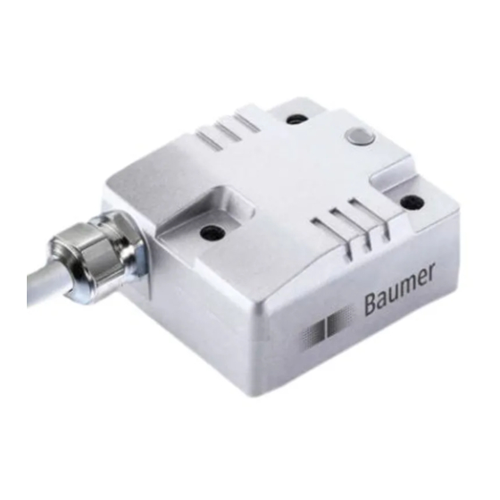
Baumer GIM500R Manual
Inclination sensor with analog interface
Hide thumbs
Also See for GIM500R:
- Manual (29 pages) ,
- Manual (13 pages) ,
- Assembly instructions (2 pages)
Table of Contents
Advertisement
Quick Links
Download this manual
See also:
Manual
Advertisement
Table of Contents

Related Manuals for Baumer GIM500R


Summary of Contents for Baumer GIM500R
- Page 1 Manual Inclination sensor GIM500R with analog interface Firmware version 1.00 and up 04.18· 174.02.077/2 Subject to modification in technic and design. www.baumer.com Errors and omissions excepted.
-
Page 2: Table Of Contents
Terminal assignment 2-dimensional ..................... 18 LED activity indicator ..........................20 4.2.1 LED green ............................20 4.2.2 LED red ..............................20 4.2.3 LED amber ............................20 4.2.4 DUO-LED in standard operation ......................20 Baumer_GIM500R_Analog_MA_EN.docx 2/20 Baumer IVO GmbH & Co. KG 11.04.18 Villingen-Schwenningen, Germany... -
Page 3: Introduction
The present manual was compiled with utmost care, errors and omissions reserved. For this reason Baumer rejects any liability for the information compiled in the present manual. Baumer nor the author will accept any liability for direct or indirect damages resulting from the use of the present information. -
Page 4: Safety And Operating Instructions
Supplementary information This manual is intended as a supplement to already existing documentation (i.e. catalogue, product information and mounting instruction). Baumer_GIM500R_Analog_MA_EN.docx 4/20 Baumer IVO GmbH & Co. KG 11.04.18 Villingen-Schwenningen, Germany... -
Page 5: Analog Interface Communication
The maximum misalignment of ±3° must not be exceeded. The sensor default position is 0° as shown in the illustration below but may be configured at will in a 2-point teaching or zeroing operation. Baumer_GIM500R_Analog_MA_EN.docx 5/20 Baumer IVO GmbH & Co. KG 11.04.18 Villingen-Schwenningen, Germany... -
Page 6: Installation Position: 2-Dimensional
Installation position: 2-dimensional 3.2.2 Inclination sensor GIM500R can be installed both in horizontal and vertical position (according to the default settings). Horizontal installation The 2-dimensional inclination sensor (housing in horizontal position) must be installed with the base plate aligned parallel to the horizontal line. The sensor can be inclined both towards the X and Y direction at the same time. -
Page 7: Output Signals
0…5 V 0…10 V 10 V 4…20 mA 4 mA 20 mA 0…20 mA 0 mA 20 mA 0…24 mA 0 mA 24 mA 0.5…4.5 V 0.5 V 5.5 V Baumer_GIM500R_Analog_MA_EN.docx 7/20 Baumer IVO GmbH & Co. KG 11.04.18 Villingen-Schwenningen, Germany... -
Page 8: Analog Output Signals 1-Dimensional
Analog output signals 1-dimensional 3.3.2 Measuring range 0…90° / 0.5...4.5 V Measuring range 0…180° / 0...10 V (0...5 V) Measuring range 0…360° Baumer_GIM500R_Analog_MA_EN.docx 8/20 Baumer IVO GmbH & Co. KG 11.04.18 Villingen-Schwenningen, Germany... -
Page 9: Analog Output Signals 2-Dimensional
Analog output signals 2-dimensional 3.3.3 Measuring range ±30° / horizontal installation Measuring range ±60° / vertical installation Measuring range ±90° / horizontal installation Baumer_GIM500R_Analog_MA_EN.docx 9/20 Baumer IVO GmbH & Co. KG 11.04.18 Villingen-Schwenningen, Germany... -
Page 10: Analog Output With Sensing Range Monitoring (Option: /4822)
0 mA 24 mA None 0.5…4.5 V Underrange, Overrange Analog output with sensing range monitoring 1-dimensional Measuring range 0…90° / 0.5…4.5V Measuring range 0…180° / 0...10 V (0...5 V) Baumer_GIM500R_Analog_MA_EN.docx 10/20 Baumer IVO GmbH & Co. KG 11.04.18 Villingen-Schwenningen, Germany... - Page 11 Measuring range 0…360° / 4...20 mA Baumer_GIM500R_Analog_MA_EN.docx 11/20 Baumer IVO GmbH & Co. KG 11.04.18 Villingen-Schwenningen, Germany...
- Page 12 Analog output with sensing range monitoring 2-dimensional Measuring range ±30° / horizontal installation / 0.5…4.5V Measuring range ±60° / vertical installation / 0...10 V (0...5 V) Measuring range ±90° / horizontal installation / 4...20 mA Baumer_GIM500R_Analog_MA_EN.docx 12/20 Baumer IVO GmbH & Co. KG 11.04.18 Villingen-Schwenningen, Germany...
-
Page 13: 2-Point Teaching Operation
Confirm position 2 Set teach input on HIGH for >0.1 sec. DUO-LED: amber continuous for 3 seconds, followed > 0.1 s by 3x flashing green. Teach input Baumer_GIM500R_Analog_MA_EN.docx 13/20 Baumer IVO GmbH & Co. KG 11.04.18 Villingen-Schwenningen, Germany... -
Page 14: Time Pattern 2-Point Teaching Operation
1 2 3 4 5 6 7 8 9 10 11 12 13 14 15 16 18 19 20 21 22 23 24 25 26 27 28 30 31 32 33 34 Ti me Baumer_GIM500R_Analog_MA_EN.docx 14/20 Baumer IVO GmbH & Co. KG 11.04.18 Villingen-Schwenningen, Germany... -
Page 15: Sensor Zeroing
2-dimensional sensors apply the zeroing operation to both directions X/Y). 1-dimensional: + 45° 2-dimensional - horizontal installation: Y axis X axis - 45° - 45° 2-dimensional - vertikal installation: X axis Y axis + 45° - 45° Baumer_GIM500R_Analog_MA_EN.docx 15/20 Baumer IVO GmbH & Co. KG 11.04.18 Villingen-Schwenningen, Germany... -
Page 16: Zeroing Operation
Set teach input on HIGH for >250 ms (≥0.7 * +Vs). Activate Sensor inclination = 0° > 250 ms Teach input Time pattern zeroing operation 3.5.2 DUO-LED HIGH 0 1 2 3 4 5 6 Baumer_GIM500R_Analog_MA_EN.docx 16/20 Baumer IVO GmbH & Co. KG 11.04.18 Villingen-Schwenningen, Germany... -
Page 17: Restore Factory Settings
Time pattern of Restore Factory Settings 3.6.2 DUO-LED HIGH 0 1 2 3 4 5 6 7 8 9 10 11 12 13 14 15 16 17 18 19 20 21 22 23 Baumer_GIM500R_Analog_MA_EN.docx 17/20 Baumer IVO GmbH & Co. KG 11.04.18 Villingen-Schwenningen, Germany... -
Page 18: Terminal Assignment And Commissioning
Voltage supply Ground connection relating to +Vs OUT_X Output OUT_Y Output Teach Teach input d.u. Do not use d.u. Do not use A_GND Ground connection related to analog Baumer_GIM500R_Analog_MA_EN.docx 18/20 Baumer IVO GmbH & Co. KG 11.04.18 Villingen-Schwenningen, Germany... - Page 19 Ground connection related to analog Wires with the same designation are internally hardwired and identical in their functions. Maximum load applied on Vs-Vs / GND-GND is 1 A each. Baumer_GIM500R_Analog_MA_EN.docx 19/20 Baumer IVO GmbH & Co. KG 11.04.18 Villingen-Schwenningen, Germany...
-
Page 20: Led Activity Indicator
DUO-LED in standard operation 4.2.4 Example for DUO-LED indications in a 2-point teaching operation, min. limit 315°, max. limit 90°. min. min. Position Position 315° 315° max. max. Position Position 90° 90° Baumer_GIM500R_Analog_MA_EN.docx 20/20 Baumer IVO GmbH & Co. KG 11.04.18 Villingen-Schwenningen, Germany...
Need help?
Do you have a question about the GIM500R and is the answer not in the manual?
Questions and answers