Sign In
Upload
Download
Table of Contents
Contents
Add to my manuals
Delete from my manuals
Share
URL of this page:
HTML Link:
Bookmark this page
Add
Manual will be automatically added to "My Manuals"
Print this page
×
Bookmark added
×
Added to my manuals
Manuals
Brands
Baumer Manuals
Accessories
OX100
Operating manual
Baumer OX100 Operating Manual
Smart profile sensors
Hide thumbs
1
2
3
4
5
6
7
8
9
10
11
12
13
14
15
16
17
18
19
20
21
22
23
24
25
26
27
28
29
30
31
32
33
34
35
36
37
38
39
40
41
42
43
44
45
46
47
48
49
50
51
52
53
54
55
56
57
58
59
60
61
62
63
64
65
66
67
68
69
70
71
72
page
of
72
Go
/
72
Contents
Table of Contents
Troubleshooting
Bookmarks
Table of Contents
List of Contents
Table of Contents
Purpose
Warnings in this Manual
Labels in this Manual
About this Document
Liability Limitation
Scope of Delivery
Name Plate
Ill. 1 Name Plate on the Sensor
Safety
Personnel Requirements
General Information
Laser
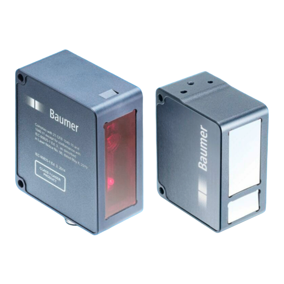
Ill. 2 Structure
Description
Structure
Sensor
Functionality
Ill. 3 Triangulation Principle
Ill. 4 Functionality
Ill. 5 Measurement Rate Limited by Exposure Time
Reference Surfaces
Ill. 6 Measurement Rate Limited by Calculation Time
Ill. 7 Reference Surfaces
Measurement Field of the Sensor
Ill. 8 Measurement Field
Ill. 9 Transmission and Receiving Axis
Ill. 10 Web Interface - Overview
Web Interface
Operating and Display Elements
Sensor Leds
Interfaces and Protocols
Modbus RTU
IO-Link
External Triggering
Transport and Storage
Transport
Delivery Inspection
Storage
Installation
General Information for Mounting
Mounting the Sensor
General Instructions for Electric Installation
Electrical Installation
Pin Assignment
Connecting the Sensor to Electricity
Commissioning
Connecting the Sensor to the PC
Tracking the Sensor's IP Address
Wiring the Sensor
Set up RS485 Interface with Modbus RTU
IO-Link Setup
Web Interface Description
Functions and Tasks
Description of the User Interface
Ill. 11 Web Interface - User Interface
Header
Menu Bar
Parametrisation Area
Footer
Visualisation Area
Window Measurement Results
Web Interface Operation
Mode Monitoring
Ill. 12 Web Interface - Monitoring Mode
Saving Measured Data as a CSV File
Mode Global Parametrization
Ill. 13 Web Interface - Global Parametrization Mode
Changing the View
Ill. 14 Web Interface - Parametrisation Mode - Result over Time & Profile View
Ill. 15 Web Interface - Parametrisation Mode - Profile & Camera Picture View
Ill. 16 Web Interface - Parametrisation Mode - Intensity & Camera Picture View
Ill. 17 Web Interface - Parametrisation Mode - Profile & Intensity View
Ill. 18 Web Interface - Parametrisation Mode - Profile View
Adjusting the Internal Resolution
Optimising the Exposure Time
Adjusting the Laser Power
Calculating the Surface Profile
Trigger Mode Setting
Aligning the Sensor (Height and Distance Mode)
Mounting Assistant
Ill. 19 Inclination Angle and Distance to the Reference Surface
Flex Mount: Compensating Mounting Angles
Ill. 20 Reference Point for Angled Installation
Ill. 21 Inclination Angle and Distance to the Reference Surface with Angled Installation
Ill. 22 Minimum Length of the the Reference Surface L
Flex Mount: Moving the Reference Surface
Ill. 23 Flex Mount: Moving the Reference Surface
Setting the Limits of the Field of View
Resetting Flex Mount
Mode Measurement Tools Parametrization
Ill. 24 Web Interface - Measurement Tools Parametrization Mode
Setting the Position Tracking (ROI Tracking)
Ill. 25 Position Tracking (ROI Tracking)
Setting the Background Tracking
Ill. 26 Background Tracking
Temporal Filter Setting
Processing an Invalid Measured Value
Mode Outputs Parametrization
Setting the Hysteresis
Ill. 27 Negative Hysteresis
Ill. 28 Positive Hysteresis
Ill. 31 Behaviour of the Switching Output in Window Mode (Positive Hysteresis)
Ill. 30 Behaviour of the Switching Output in Point Mode (Negative Hysteresis)
Ill. 29 Behaviour of the Switching Output in Point Mode (Positive Hysteresis)
Mode Save Parameter-Setups
Ill. 32 Behaviour of the Switching Output in Window Mode (Negative Hysteresis)
Ill. 33 Web Interface - Save Parameter Setup Mode
Mode Device Configuration
Ill. 34 Web Interface - Device Configuration Mode
Preventive Maintenance
Cleaning the Sensor
Troubleshooting
Resetting the Sensor to the Factory Settings
Return and Repair
Accessories
Technical Data
Dimensional Drawing
Ill. 35 Dimensional Drawing
List of Illustrations
Advertisement
Quick Links
1
Modbus Rtu
Download this manual
Operating Manual
OX100
EN-US
Smart Profile sensors
Table of
Contents
Previous
Page
Next
Page
1
2
3
4
5
Advertisement
Chapters
List of Contents
2
List of Illustrations
68
Table of Contents
Need help?
Do you have a question about the OX100 and is the answer not in the manual?
Ask a question
Questions and answers
Related Manuals for Baumer OX100
Accessories Baumer PosCon OXH7 Manual
Sensor with tcp/ip interface (98 pages)
Accessories Baumer OXE7.E15T-11148276 User Manual
Photoelectric sensors (4 pages)
Accessories Baumer OX200 Operating Manual
Smart profile sensors (114 pages)
Accessories Baumer PosCon OXE7 Operating Instructions Manual
(75 pages)
Accessories Baumer OXM100 Operating Manual
Smart profile sensors (72 pages)
Accessories Baumer OXM100-R05V.001 Operating Manual
Smart profile sensors (72 pages)
Accessories Baumer OXM100-R10V.001 Operating Manual
Smart profile sensors (72 pages)
Accessories Baumer OXC7-11170024 Mounting Instructions
Circle measurement sensor (4 pages)
Accessories Baumer OM70 multi-spot Operating Instructions Manual
(60 pages)
Accessories Baumer O200 Instruction Manual
Sensors with io-link (34 pages)
Accessories Baumer OM30 IO-Link Operating Manual
Laser distance sensor (52 pages)
Accessories Baumer PosCon3D Operating Instructions Manual
Edge sensor (64 pages)
Accessories Baumer CombiTemp TFRH Operating Instructions Manual
Temperature sensor (12 pages)
Accessories Baumer UNCK 09U6914/D1 Manual
Distance measuring sensor with analog output 0 - 10 v (3 pages)
Accessories Baumer CleverLevel LBFS Series Operating Instructions Manual
Level measurement, point level detection (48 pages)
Accessories Baumer GIM500R Manual
Inclination sensor with analog interface (20 pages)
This manual is also suitable for:
Oxm100
Oxm100-r05v.001
Oxm100-r10v.001
Table of Contents
Print
Rename the bookmark
Delete bookmark?
Delete from my manuals?
Login
Sign In
OR
Sign in with Facebook
Sign in with Google
Upload manual
Upload from disk
Upload from URL


Need help?
Do you have a question about the OX100 and is the answer not in the manual?
Questions and answers