Sign In
Upload
Manuals
Brands
Baumer Manuals
Accessories
OX200
Baumer OX200 Manuals
Manuals and User Guides for Baumer OX200. We have
2
Baumer OX200 manuals available for free PDF download: Operating Manual
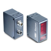
Baumer OX200 Operating Manual (124 pages)
Smart Profile sensors
Brand:
Baumer
| Category:
Security Sensors
| Size: 5 MB
Table of Contents
List of Contents
2
Table of Contents
2
1 About this Document
5
Purpose
5
Warnings in this Manual
5
Labels
6
Liability Limitation
6
Scope of Delivery
6
Name Plate
7
Ill. 1 Name Plate on the Sensor
7
2 Safety
8
Intended Use
8
Personnel Requirements
8
General Safety Instructions
9
3 Description
10
Sensor
10
Structure
10
Ill. 2 OX200 - Structure
10
Functionality
11
Ill. 3 OX200 - Triangulation Principle
11
Ill. 4 OXM200 - Functionality
12
Ill. 5 OXP200 - Functionality
12
Ill. 6 OX200 - Measurement Rate Limited by the Exposure Time
13
Ill. 7 OX200 - Measurement Rate Limited by the Calculation Time
13
Reference Surfaces
14
Ill. 8 OX200 - Reference Surfaces
14
Measurement Field of the Sensor
15
Ill. 9 OX200 - Measurement Field
15
Ill. 10 OX200 - Transmission and Receiving Axes
16
Operating and Display Elements
17
Web Interface
17
Ill. 11 Web Interface - Overview
17
Sensor Leds
18
Ill. 12 OX200 - Leds on the Sensor
18
Interfaces and Protocols
19
Industrial Ethernet [OXM]
20
Profinet [OXM]
22
Ethernet/Ip [OXM]
24
Ill. 13 Load New Parameter Setup (Error)
30
Ill. 14 Load New Parameter Setup (Success)
31
Modbus TCP [OXM]
32
Opc Ua [Oxm]
37
Ill. 15 OPC UA - Uaexpert Client - Surface
37
IO-Link
41
Udp
42
Ill. 16 Web Interface - Mode Outputs Parametrization - UDP
42
Ill. 17 UDP - Packet Framing Example
43
Ill. 18 UDP - Body Recomposition Example
43
Sdk
48
Ill. 19 SDK - Structure
48
External Triggering
51
Ill. 20 Encoder - 2-Channel Operation
52
4 Transport and Storage
53
Transport
53
Delivery Inspection
53
Storage
53
5 Installation
54
General Information for Mounting
54
Mounting the Sensor
55
Ill. 21 OX200 - Side Mounting
55
Ill. 22 OX200 - Head End Mounting
55
6 Electrical Installation
56
Pin Assignment
56
Ill. 23 Ethernet Connection, M12 8-Pin, X-Coded, Female
56
Ill. 24 OXM200 - Electrical Connection, M12 12-Pin, A-Coded, Male
57
Ill. 25 OXP200 - Electrical Connection, M12 12-Pin, A-Coded, Male
57
Connecting the Sensor to Electricity
58
7 Commissioning
59
Connecting the Sensor to the PC
59
Ill. 26 Entering the IP Address of the Sensor
59
Allocating an IP Address to the PC
60
Tracking the Sensor's IP Address
61
Profinet: Integrating the Sensor in the PLC [OXM]
62
Wiring the Sensor [OXM]
62
Connecting the Sensor to the PLC [OXM]
63
Integrating the Sensor into the PLC Project [OXM]
65
Changing the Parameter Setup
66
Ethernet/Ip: Integrating the Sensor in the PLC [OXM]
66
Wiring the Sensor [OXM]
66
Connecting the Sensor to the PLC [OXM]
67
Integrating the Sensor into the PLC Project [OXM]
71
Reading/Changing Parameter Setup Via Parameter 151
74
Additional Information about Accessing Cyclic Process Data
77
Additional Notes about Ethernet/Ip Objects
78
Modbus TCP: Integrating the Sensor in the PLC [OXM]
78
OPC UA: Adding Sensor in Uaexpert Client [OXM]
79
Setting up IO-Link [OXM]
80
Ill. 27 OXM200 - Electrical Connection, M12 12-Pin, A-Coded, Male
80
8 Web Interface Description
81
Functions and Tasks
81
Description of the User Interface
81
Ill. 28 Web Interface - User Interface
81
Header
82
Menu Bar
83
Window Measurement Results
84
Footer
84
Visualisation Area
84
Parametrisation Area
84
9 Web Interface Operation
85
Mode Monitoring
85
Ill. 29 Web Interface - Monitoring Mode
85
Saving Measured Data as a CSV File
86
Mode Global Parametrization
87
Changing the View
87
Ill. 30 Web Interface - Global Parametrization Mode
87
Ill. 31 Web Interface - Parametrisation Mode - Result over Time & Profile View
88
Ill. 32 Web Interface - Parametrisation Mode - Profile & Camera Picture View
89
Ill. 33 Web Interface - Parametrisation Mode - Intensity & Camera Picture View
90
Ill. 34 Web Interface - Parametrisation Mode - Profile & Intensity View
91
Ill. 35 Web Interface - Parametrisation Mode - Profile View
92
Adjusting the Internal Resolution
93
Optimising the Exposure Time
93
Adjusting the Laser Power
94
Calculating the Surface Profile
95
Trigger Mode Setting
96
Aligning the Sensor (Height and Distance Mode)
97
Mounting Assistant
98
Ill. 36 OX200 - Tilt Angle and Distance to the Reference Surface
98
Flex Mount: Compensating Mounting Angles
99
Ill. 37 OX200 - Reference Point for Angled Mounting
99
Ill. 38 OX200 - Tilt Angle and Distance to the Reference Surface with Angled Mounting
100
Ill. 39 OX200 - Minimum Length of the Reference Surface L
101
Flex Mount: Moving the Reference Surface
102
Ill. 40 OX200 - Flex Mount - Moving the Reference Surface
102
Resetting Flex Mount
103
Setting the Limits of the Field of View
103
Mode Measurement Tools Parametrization
104
Ill. 41 Web Interface - Measurement Tools Parametrization Mode
104
Setting the Position Tracking (ROI Tracking) [OXM]
105
Ill. 42 OX200 - Position Tracking (ROI Tracking)
105
Setting Background Tracking [OXM]
106
Ill. 43 OX200 - Background Tracking
106
Setting the Temporal Filter [OXM]
107
Processing an Invalid Measured Value [OXM]
107
Outputs Parametrization Mode [OXM]
108
Setting the Hysteresis [OXM]
110
Ill. 44 OX200 - Negative Hysteresis
110
Ill. 45 OX200 - Positive Hysteresis
110
Ill. 46 Behaviour of the Switching Output in Point Mode (Positive Hysteresis)
111
Ill. 47 Behaviour of the Switching Output in Point Mode (Negative Hysteresis)
111
Ill. 48 Behaviour of the Switching Output in Window Mode (Positive Hysteresis)
112
Ill. 49 Behaviour of the Switching Output in Window Mode (Negative Hysteresis)
112
Mode Save Parameter-Setups
113
Ill. 50 Web Interface - Save Parameter Setup Mode
113
Mode Device Configuration
114
Ill. 51 Web Interface - Device Configuration Mode
114
10 Preventive Maintenance
116
Cleaning the Sensor
116
11 Troubleshooting
117
Resetting the Sensor to the Factory Settings
117
Return and Repair
117
Disposal
117
Accessories
117
12 Technical Data
118
Dimensional Drawing
118
Ill. 52 OX200 - Dimensional Drawing
118
List of Illustrations
119
Advertisement
Baumer OX200 Operating Manual (114 pages)
Smart Profile sensors
Brand:
Baumer
| Category:
Accessories
| Size: 5 MB
Table of Contents
List of Contents
2
Table of Contents
2
1 About this Document
5
Purpose
5
Warnings in this Manual
5
Labels
6
Liability Limitation
6
Scope of Delivery
6
Name Plate
7
Ill. 1 Name Plate on the Sensor
7
2 Security
8
Intended Use
8
Personnel Requirements
8
General Safety Instructions
9
3 Description
10
Sensor
10
Structure
10
Ill. 2 OX200 - Structure
10
Functionality
11
Ill. 3 OX200 - Triangulation Principle
11
Ill. 4 OXM200 - Functionality
12
Ill. 5 OXP200 - Functionality
12
Ill. 6 OX200 - Measurement Rate Limited by the Exposure Time
13
Ill. 7 OX200 - Measurement Rate Limited by the Calculation Time
13
Reference Surfaces
14
Ill. 8 OX200 - Reference Surfaces
14
Field of View of the Sensor
15
Ill. 9 OX200 - Field of View
15
Ill. 10 OX200 - Transmission and Receiving Axes
16
Operating and Display Elements
17
Web Interface
17
Ill. 11 Web Interface - Overview
17
Sensor Leds
18
Ill. 12 OX200 - Leds on the Sensor
18
Interfaces and Protocols
19
Industrial Ethernet [OXM]
20
Profinet [OXM]
22
Ethernet/Ip [OXM]
24
Modbus TCP [OXM]
25
Opc Ua [Oxm]
29
Ill. 13 OPC UA - Uaexpert Client - Surface
29
IO-Link [OXM]
33
Udp
34
Ill. 14 Web Interface - Mode Outputs Parametrization - UDP
34
Ill. 15 UDP - Packet Framing Example
35
Ill. 16 UDP - Body Recomposition Example
35
Sdk
40
Ill. 17 SDK - Structure
40
External Triggering
43
Ill. 18 Encoder - 2-Channel Operation
44
4 Transport and Storage
45
Transport
45
Delivery Inspection
45
Storage
45
5 Mounting
46
General Information for Mounting
46
Mounting the Sensor
47
Ill. 19 OX200 - Side Mounting
47
Ill. 20 OX200 - Head End Mounting
47
6 Electrical Installation
48
Pin Assignment
49
Ill. 21 Ethernet Connection, M12 8-Pin, X-Coded, Female
49
Ill. 22 OXM200 - Electrical Connection, M12 12-Pin, A-Coded, Male
49
Connecting the Sensor to Electricity
50
Ill. 23 OXP200 - Electrical Connection, M12 12-Pin, A-Coded, Male
50
7 Commissioning
51
Connecting the Sensor to the PC
51
Ill. 24 Entering the IP Address of the Sensor
51
Allocating an IP Address to the PC
52
Determining the IP Address of the Sensor
53
Profinet: Integrating the Sensor in the PLC [OXM]
54
Wiring the Sensor [OXM]
54
Connecting the Sensor to the PLC [OXM]
55
Integrating the Sensor into the PLC Project [OXM]
57
Changing the Parameter Setup
58
Ethernet/Ip: Integrating the Sensor in the PLC [OXM]
58
Wiring the Sensor [OXM]
58
Connecting the Sensor to the PLC [OXM]
59
Integrating the Sensor into the PLC Project [OXM]
63
Reading/Changing Parameter Setup Via Parameter 151
66
Additional Information about Accessing Cyclic Process Data
69
Additional Notes about Ethernet/Ip Objects
70
Modbus TCP: Integrating the Sensor in the PLC [OXM]
70
OPC UA: Adding Sensor in Uaexpert Client [OXM]
71
Setting up IO-Link [OXM]
72
Ill. 25 OXM200 - Electrical Connection, M12 12-Pin, A-Coded, Male
72
8 Web Interface Description
73
Functions and Tasks
73
Description of the User Interface
73
Ill. 26 Web Interface - User Interface
73
Header Area
74
Menu Bar
75
Measurement Results Window
76
Footer Area
76
Visualisation Area
76
Parametrisation Area
76
9 Web Interface Operation
77
Monitoring Mode
77
Ill. 27 Web Interface - Monitoring Mode
77
Saving Measured Data as a CSV File
78
Global Parametrization Mode
79
Changing the View
79
Ill. 28 Web Interface - Global Parametrization Mode
79
Ill. 29 Web Interface - Parametrisation Mode - Result over Time & Profile View
80
Ill. 30 Web Interface - Parametrisation Mode - Profile & Camera Picture View
81
Ill. 31 Web Interface - Parametrisation Mode - Intensity & Camera Picture View
82
Ill. 32 Web Interface - Parametrisation Mode - Profile & Intensity View
83
Ill. 33 Web Interface - Parametrisation Mode - Profile View
84
Adjusting the Internal Resolution
85
Optimising the Exposure Time
85
Adjusting the Laser Power
86
Calculating the Surface Profile
87
Trigger Mode Setting
88
Aligning the Sensor (Height and Distance Mode)
89
Mounting Assistant
90
Ill. 34 OX200 - Tilt Angle and Distance to the Reference Surface
90
Flex Mount: Compensating Mounting Angles
91
Ill. 35 OX200 - Reference Point for Angled Mounting
91
Ill. 36 OX200 - Tilt Angle and Distance to the Reference Surface with Angled Mounting
92
Ill. 37 OX200 - Minimum Length of the Reference Surface L
93
Flex Mount: Moving the Reference Surface
94
Ill. 38 OX200 - Flex Mount - Moving the Reference Surface
94
Resetting Flex Mount
95
Setting the Limits of the Field of View
95
Measurement Tools Parametrization Mode [OXM]
96
Setting the Position Tracking (ROI Tracking) [OXM]
97
Setting Background Tracking [OXM]
98
Setting the Temporal Filter [OXM]
99
Processing an Invalid Measured Value [OXM]
99
Outputs Parametrization Mode [OXM]
100
Setting the Hysteresis [OXM]
102
Save Parameter-Setups Mode
105
Device Configuration Mode
106
10 Preventive Maintenance
108
Cleaning the Sensor
108
11 Troubleshooting
109
Resetting the Sensor to the Factory Settings
109
Return and Repair
109
Disposal
109
Accessories
109
12 Technical Data
110
Dimensional Drawing
110
List of Illustrations
111
Advertisement
Related Products
Baumer PosCon OXH7
Baumer PosCon OXE7
Baumer OX100
Baumer OXM100
Baumer OXM100-R05V.001
Baumer OXM100-R10V.001
Baumer OM30-L0350.HV.YIN
Baumer OM30-L0100.HV.YUN
Baumer OM20-P0120.HH.YUN
Baumer OM30-P0100.HV.YUN
Baumer Categories
Accessories
Media Converter
Security Sensors
Measuring Instruments
Portable Generator
More Baumer Manuals
Login
Sign In
OR
Sign in with Facebook
Sign in with Google
Upload manual
Upload from disk
Upload from URL