Baumer OM30 IO-Link Operating Manual
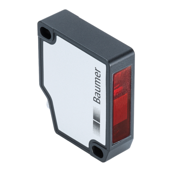
Laser distance sensor
Hide thumbs
Also See for OM30 IO-Link:
- Operating manual (48 pages) ,
- Operating manual (52 pages) ,
- Operating manual (54 pages)
Table of Contents
Advertisement
Quick Links
Advertisement
Chapters
Table of Contents

Subscribe to Our Youtube Channel
Related Manuals for Baumer OM30 IO-Link


Summary of Contents for Baumer OM30 IO-Link
- Page 1 Operating Manual OM20/OM30 IO-Link EN-US Laser distance sensor...
-
Page 2: Table Of Contents
Pin assignment............................ 22 Connection diagram ..........................22 Connecting the sensor to electricity ....................22 7 Commissioning ............................23 Factory settings........................... 23 Setting up IO-Link ..........................23 8 Functions ..............................24 Filter ..............................24 Trigger mode............................27 Operating Manual OM20/OM30 IO-Link | V6... - Page 3 10 Preventive maintenance ..........................45 10.1 Cleaning the sensor ..........................45 11 Troubleshooting ............................46 11.1 Return and repair ..........................46 11.2 Accessories............................46 12 Annex ................................47 12.1 Analog output resolution - diagrams ....................47 V6 | OM20/OM30 IO-Link Operating Manual...
-
Page 4: About This Document
In addition, the local occupational health and safety regulations and general safety regulations apply. The illustrations in this manual are examples only. Deviations are at the discretion of Baumer at all times. Warnings in this manual Warnings draw attention to injury or material damage. -
Page 5: Labels In This Manual
Name plate Swiss made Ill. 1: Name plate Short item name (OMxx item number) Production date Serial number V6 | OM20/OM30 IO-Link Operating Manual... -
Page 6: Scope Of Delivery
In addition, you can find the following information, among other things, in digital format at www.baumer.com: Operating manual Data sheet 3D CAD drawing Quickstart Dimensional drawing Connection diagram & pin assignment IODD file Certificates (EU conformity declaration, etc.) Operating Manual OM20/OM30 IO-Link | V6... -
Page 7: Safety
Used electrical and electronic devices may not be disposed of in household waste. The product contains valuable raw materials that can be recycled. There- fore dispose of this product at the appropriate collection point. For additional in- formation visit www.baumer.com. V6 | OM20/OM30 IO-Link Operating Manual... -
Page 8: Laser
Complies with 21 CFR 1040.10 and 1040.11 except for conformance with IEC 60825-1 Ed. 3., as described in Laser Notice No. 56, dated May 8, 2019 Products with the following type codes are rated as Laser Class 2: OM20-xxxxx.HV.xxx OM30-xxxxx.HV.xxx Operating Manual OM20/OM30 IO-Link | V6... -
Page 9: Description
Digital IO-Link interface Analog output The following options are available to you for parameterizing the sensor: IO-Link parameter Teach button on the sensor V6 | OM20/OM30 IO-Link Operating Manual... -
Page 10: Measurement Field
The following values depend on the zero position: ▪ Output measured values ▪ Analog value ▪ Switching points Capable of parameterization via: ▪ IO-Link ▪ Teach button Operating Manual OM20/OM30 IO-Link | V6... -
Page 11: Operating And Display Elements
Result: ü Teach-in OK: Green and yellow LEDs light up briefly. Afterwards, the sensor returns to oper- ating mode. ü Teach-in not OK: Green and yellow LEDs blink simultaneously with 8 Hz. V6 | OM20/OM30 IO-Link Operating Manual... -
Page 12: Ill. 3 Analog Measurement Field (Inverted)
Yellow and green LEDs blink simultaneously with 2 Hz. Result: ü Teach-in OK: Green and yellow LEDs light up briefly. Afterwards, the sensor goes back to operating mode. ü Teach-in not OK: Yellow and green LEDs blink simultaneously with 8 Hz. Operating Manual OM20/OM30 IO-Link | V6... -
Page 13: Analog Measurement Performance
In this example, the repeatability of the sensor is specified as 1 µm at the beginning of the mea- suring range to 3 µm at the end of the measuring range. This precision can be achieved at the analog output by narrowing the analog measuring field to 3 mm. V6 | OM20/OM30 IO-Link Operating Manual... -
Page 14: Io-Link
▪ Find me (localizing the sensor by activating the LEDs) ▪ Laser on/off Input: ▪ Measured value ▪ Scale of the measured value ▪ Status of the alarm output ▪ Status of the signal quality ▪ Status of the switching output Operating Manual OM20/OM30 IO-Link | V6... - Page 15 Boolean Status of the switching output. (Switching Signal ▪ Bit 0 = 0: Switching output is inac- Channel 1) tive. ▪ Bit 0 = 1: Switching output is active. MDC = Measurement Data Channel V6 | OM20/OM30 IO-Link Operating Manual...
- Page 16 Exposure reserve Signal quality Device status Operating time Histogram function For a detailed description of the IO-Link functions, see Functions [} 24]. For a detailed descrip- tion of the diagnostic data, see Diagnostic data [} 39]. Operating Manual OM20/OM30 IO-Link | V6...
-
Page 17: Dimensional Drawing
Baumer Description Dimensional drawing 34,5 31,6 Teach-in Ill. 4: Dimensional drawing OM20 40,3 13,6 Teach-in Ill. 5: Dimensional drawing OM30 V6 | OM20/OM30 IO-Link Operating Manual... -
Page 18: Transport And Storage
Keep away from the sun. Avoid mechanical agitation. Storage temperature: -10 ... +60 °C Ambient humidity: 20 ... 85 % When storing for longer than 3 months, regularly check the general state of all parts and the packaging. Operating Manual OM20/OM30 IO-Link | V6... -
Page 19: Installation Instructions
Baumer Installation instructions Installation instructions INFO You can find the suitable installation accessories on the Baumer website. Go to www.baumer.com for this. Then enter the item number of the sensor in the search field of the website. For measurement objects with shiny surfaces: Tilt the sensor 6 to 10° to the side so that the light directly reflected by the surface does not hit the receiver of the sensor. - Page 20 Prevent the ambient light from entering the detection range of the receiver. û ü Mounting several sensors close to each other: Prevent the detection ranges of the receivers from overlapping. Only the sensor’s own laser spot may be in the detection range of the receiver. Operating Manual OM20/OM30 IO-Link | V6...
- Page 21 Baumer Installation instructions ü û Mounting for round measurement objects: Align the sensor on the same axis as the measurement object to prevent reflections. V6 | OM20/OM30 IO-Link Operating Manual...
-
Page 22: Electrical Installation
/ IO-Link BU (3) BU – Blue BK – Black Connecting the sensor to electricity Instruction: a) Ensure that the system is disconnected from power. b) Connect the sensor according to the pin assignment. Operating Manual OM20/OM30 IO-Link | V6... -
Page 23: Commissioning
Setting up IO-Link Instruction: w Download the IODD file for the sensor from one of the following two websites (the IODD file can be found via the item number of the sensor): www.baumer.com ioddfinder.io-link.com V6 | OM20/OM30 IO-Link Operating Manual... -
Page 24: Functions
The median value is the mea- sured value located right “in the center” if the measured values are sorted by size. Time Ill. 6: Moving Median filter Raw data Data after filtering with Moving Median Operating Manual OM20/OM30 IO-Link | V6... -
Page 25: Ill. 7 Moving Average Filter
Very High Highest INFO When several sensors are calculated, for example, for thickness measurement, the Standard fil- ter should always be chosen to obtain a raw measured value of both sensors for further calcula- tions. V6 | OM20/OM30 IO-Link Operating Manual... - Page 26 Custom: Enter the filter length as a nu- merical value. MovAvgFilter.Custom Mov- Freely configurable filter length for Mov- ing Average Length ing Average. MovMedianFilter.Custom Freely configurable filter length for Mov- Moving Median Length ing Median. Operating Manual OM20/OM30 IO-Link | V6...
-
Page 27: Trigger Mode
IO-Link parameter: Sampling Mode (Trigger) operating mode Parameter name Values Description OperationMode.Sampling Trigger mode Free Running, Mode Interval OperationMode.Sampling Time interval for the Interval trigger Time mode V6 | OM20/OM30 IO-Link Operating Manual... -
Page 28: Zero Position
Parameter name Values Description Zero Position.Zero Position Zero position Baumer commands – Zero Position Teach Teach in the current position as the new zero position. Measurement range With the Measurement range function, the limits of the measurement range can be set so that the active measurement range is limited to a partial range of the maximum measurement range of the sensor. -
Page 29: Invalid Value Handling
The last valid value is maintained during the time period. The type of Invalid Value Handling has no effect yet at this point. Digital output Analog output Hold Time Hold Time Hold Time Hold Time Signal quality Ill. 8: Invalid Value Handling – example 1 V6 | OM20/OM30 IO-Link Operating Manual... - Page 30 ▪ Last valid: Last valid measured value near, far ▪ near: min. output point ▪ far: max. output point Process Value Disruption Time period during which an invalid mea- Filter.Hold Time sured value is suppressed. Operating Manual OM20/OM30 IO-Link | V6...
-
Page 31: Switching Points
▪ Window mode (SP1 and SP2) Point, Window SSC1 Param.SP1 Distance at which the SSC1 is activated or inacti- vated. SSC1 Param.SP2 Distance at which the SSC1 is activated or inacti- vated. Only relevant for window mode. V6 | OM20/OM30 IO-Link Operating Manual... -
Page 32: Polarity
Window mode: The switching output is activated as soon as the measured value is outside the window of SP1 and SP2. IO-Link parameter: Polarity Parameter name Values Description SSC1 Config.Polarity Polarity of the switching output Active Low, Ac- tive High Operating Manual OM20/OM30 IO-Link | V6... -
Page 33: Hysteresis
The Hysteresis prevents unwanted switching of the switching output. The parameterized value of the hysteresis is the difference in distance between the points at which the switching output is activated and deactivated. Baumer recommends always setting the hysteresis not equal to 0. Positive hysteresis... -
Page 34: Ill. 16 Behavior Of The Switching Output In Point Mode (Positive Hysteresis)
Level Ill. 16: Behavior of the switching output in point mode (positive hysteresis) Negative hysteresis: Switching point P1 Hysteresis High Active low level Level Ill. 17: Behavior of the switching output in point mode (negative hysteresis) Operating Manual OM20/OM30 IO-Link | V6... -
Page 35: Ill. 18 Behavior Of The Switching Output In Window Mode (Positive Hysteresis)
Active high level Ill. 19: Behavior of the switching output in window mode (negative hysteresis) IO-Link parameter: Hysteresis Parameter name Values Description Hysteresis.SSC1 Width Enter the hysteresis as a positive or negative nu- merical value (in mm). V6 | OM20/OM30 IO-Link Operating Manual... -
Page 36: Function Of The Output
Max. limit of the analog measurement range range Zero position You have the option of inverting the characteristic curve of the analog measurement field. not inverted (pos. sensitivity) inverted (neg. sensitivity) Distance Ill. 21: Analog measurement field – inverted Operating Manual OM20/OM30 IO-Link | V6... - Page 37 Teach in max. limit of the analog mea- Output Scale at Analog Max surement range (alternatively to the Teach button) Baumer commands – Output Set the analog measurement range to the Scale is set to the possible max. max. possible limits V6 | OM20/OM30 IO-Link Operating Manual...
-
Page 38: Function Of The Teach Button
Teach button should be deactivated after a teach-in process (in min). With a value of 0, the Teach button is always activated. With a value of 255 (0xFF), the Teach button is perma- nently deactivated. Operating Manual OM20/OM30 IO-Link | V6... -
Page 39: Diagnostic Data
The measure- ment and change of the output always take place with the same frequency. IO-Link diagnostic data: Measurement rate Name Description Measurement Values. PV1 Rate Output of the measuring rate. V6 | OM20/OM30 IO-Link Operating Manual... -
Page 40: Response Delay
Use the histogram function for this purpose (Histogram function [} 42]). IO-Link diagnostic data: Exposure reserve Name Description Exposure Reserve. Exposure Reserve Output of the exposure reserve. Operating Manual OM20/OM30 IO-Link | V6... -
Page 41: Signal Quality
Output of the operating time since the last power up. Operation Time.Resetable Output of the operating time since an individually configurable point in time (by reset). Operation Time.Lifetime Operating time since the initial power up. V6 | OM20/OM30 IO-Link Operating Manual... -
Page 42: Histogram Function
Bin 2 75 mm < 100 mm Bin 3 100 mm < 125 mm Bin 4 125 mm < 150 mm Bin 5 150 mm < 175 mm Example of a recorded distance histogram: Operating Manual OM20/OM30 IO-Link | V6... - Page 43 0. This results in the following distribution: Number of Value range min. Value range max. measurements Bin 1 < 5 Bin 2 < 10 Bin 3 < 15 Bin 4 < 20 Bin 5 < 25 V6 | OM20/OM30 IO-Link Operating Manual...
- Page 44 Exposure Reserve Resetable Histogram.Range Start Start of valid range Exposure Reserve Resetable Histogram.Range End End of valid range Exposure Reserve Resetable Histogram.Nbr of Bins Number of intervals/bins Exposure Reserve Resetable Histogram.Bin 1 - 20 Bin 1 - 20 Operating Manual OM20/OM30 IO-Link | V6...
-
Page 45: Preventive Maintenance
Do not use scouring agents, solvents, or other aggressive cleaning agents. c) Do not use jets of liquid for cleaning, for example, a high-pressure cleaner. d) Do not scrape off contamination with sharp-edged items. Interior cleaning No interior cleaning of the sensor is required. V6 | OM20/OM30 IO-Link Operating Manual... -
Page 46: Troubleshooting
Remedy: Reduce the ambient light (e. g. with a cover). 11.1 Return and repair In case of complaints, please contact the relevant sales company. 11.2 Accessories You can find accessories at the website at: https://www.baumer.com Operating Manual OM20/OM30 IO-Link | V6... -
Page 47: Annex
The following diagrams show the resolution of the analog output in relation to the measuring distance for the different sensor types. The type code of the sensor shown is indicated in the caption. Ill. 23: Characteristic curves for OM20-x0026.xx.Yxx Ill. 24: Characteristic curves for OM20-x0120.xx.Yxx V6 | OM20/OM30 IO-Link Operating Manual... -
Page 48: Ill. 25 Characteristic Curves For Om30-X0100.Xx.yxx
Annex Baumer Ill. 25: Characteristic curves for OM30-x0100.xx.Yxx Ill. 26: Characteristic curves for OM30-x0350.xx.Yxx Operating Manual OM20/OM30 IO-Link | V6... -
Page 49: Ill. 27 Characteristic Curves For Om30-X0550.Xx.yxx
Baumer Annex Ill. 27: Characteristic curves for OM30-x0550.xx.Yxx V6 | OM20/OM30 IO-Link Operating Manual... - Page 50 Characteristic curves for OM20-x0026.xx.Yxx ..................47 Ill. 24 Characteristic curves for OM20-x0120.xx.Yxx ..................47 Ill. 25 Characteristic curves for OM30-x0100.xx.Yxx ..................48 Ill. 26 Characteristic curves for OM30-x0350.xx.Yxx ..................48 Ill. 27 Characteristic curves for OM30-x0550.xx.Yxx ..................49 Operating Manual OM20/OM30 IO-Link | V6...
- Page 52 Baumer Electric AG Hummelstrasse 17 CH − 8501 Frauenfeld www.baumer.com...
Need help?
Do you have a question about the OM30 IO-Link and is the answer not in the manual?
Questions and answers