Table of Contents
Advertisement
Quick Links
Advertisement
Table of Contents
Troubleshooting

Related Manuals for Barco Event Master E2 Lite


Summary of Contents for Barco Event Master E2 Lite
- Page 1 E2 Lite and EC-40 User’s Guide ENABLING BRIGHT OUTCOMES...
- Page 2 Barco Inc, Image Processing 3078 Prospect Park Drive, Rancho Cordova, CA , 95670, USA www.barco.com/en/support www.barco.com Registered office: Barco NV President Kennedypark 35, 8500 Kortrijk, Belgium www.barco.com/en/support www.barco.com...
- Page 3 Barco. If the purchaser or a third party carries out modifications or repairs on goods delivered by Barco, or if the goods are handled incorrectly, in particular if the systems are operated incorrectly or if, after the transfer of risks, the goods are subject to influences not agreed upon in the contract, all guarantee claims of the purchaser will be rendered invalid.
- Page 4 Changes or modifications not expressly approved by the party responsible for compliance could void the user's authority to operate the equipment FCC responsible: Barco Inc. 3059 Premiere Parkway Suite 400 30097 Duluth GA, United States Tel: +1 678 475 8000...
-
Page 5: Table Of Contents
The Screen management system.............................13 2 Safety...........................................15 General considerations...................................16 Important safety instructions................................16 3 General ..........................................19 Event Master devices overview ..............................20 Event Master E2 Lite processors features...........................21 Event Master EC-40 controller features ..........................23 Terms and definitions..................................23 Control overview....................................26 Presentation System overview..............................27 Installation requirements................................28 Initial inspection....................................29... - Page 6 5.10 System menu > VFD brightness (display brightness) ....................58 5.11 System menu > Diagnostics ................................58 5.12 System menu > Lock front panel...............................62 5.13 Using the Tech Support menu..............................62 5.14 Restoring Factory Default Settings ............................62 5.15 Firmware Upgrade.....................................63 5.16 Save All........................................64 6 EM GUI orientation....................................65 General requirements..................................67 Download of Event Master Toolset Software........................67...
- Page 7 Restoring the system ..................................173 User preference setup.................................. 174 Saving the setup....................................174 Backing up the system ................................. 174 7.10 Configuration Menu > Initial Setup ............................175 7.11 Configuration Menu > Add Inputs ............................176 7.12 Configuration Menu > Add Outputs ............................177 7.13 Configuration Menu >...
- Page 8 12Preventive maintenance actions ............................221 12.1 E2 Lite maintenance actions..............................222 12.2 EC-40 maintenance actions..............................222 13E2 Lite Maintenance..................................223 13.1 E2 Lite unit Overview ..................................225 13.2 Process Overview................................... 226 13.3 Spare Parts Serviceable by All Users ..........................227 13.4 Rear I/O Cards....................................
- Page 9 Standard connector pinouts ..............................296 B Remote Control Protocol ................................301 Event Master series processor ASCII remote control ....................302 Event Master series processor JSON RPC remote control ..................303 C Troubleshooting..................................... 317 Troubleshooting List ..................................318 D Third Party Software Acknowledgements........................321 Third Party Software list ................................
- Page 10 R5909934 /00 E2 Lite and EC-40...
-
Page 11: Introduction
Introduction Overview • About this guide • Record of changes • Symbols, pictures and fonts • The Screen management system R5909934 /00 E2 Lite and EC-40... -
Page 12: About This Guide
This manual This User's guide describes how to install and operate the Event Master E2 Lite video processor and the EC- 40 controller. The User's Guide is designed to be a reference tool in the everyday work of the user with the product. -
Page 13: The Screen Management System
Introduction Note: gives extra information about the described subject Tip: gives extra advice about the described subject Picture overview Images and pictures given in the manual are used as illustration. The content of the images can be slightly different with the reality, e.g. version numbers, device types, installed modules, form and position of software windows on screen. - Page 14 Introduction R5909934 /00 E2 Lite and EC-40...
-
Page 15: Safety
Safety About this chapter Please read this chapter carefully. It contains important information to prevent personal injury while installing and operating Event Master devices. Furthermore, it includes several cautions to prevent damage to the Event Master devices. Ensure that you understand and follow all safety guidelines, safety instructions and warnings mentioned in this chapter before you begin installation. -
Page 16: General Considerations
• FRAGILE: Event Master devices are fragile. Handle these devices with care at all times. • To prevent injury, minimum 2 persons are required to carry an Event Master E2 Lite processor. R5909934 /00 E2 Lite and EC-40... - Page 17 Refer cord and connector changes to qualified service personnel. • Replace spare parts only with the same parts supplied by Barco. • Save the original shipping carton and packing material. They will come in handy if you ever have to ship your equipment.
- Page 18 Safety R5909934 /00 E2 Lite and EC-40...
-
Page 19: General
About this chapter This chapter is designed to introduce you to the Event Master series products. Overview • Event Master devices overview • Event Master E2 Lite processors features • Event Master EC-40 controller features • Terms and definitions •... -
Page 20: Event Master Devices Overview
While the functionality is limited compared to the Event Master series, E2 Lite offers all the features and performance needed for most mid-sized performances, without compromising the image quality of the Barco brand, while being more competitively priced. E2 Lite supports 32 single-layer layers, or 16 mixed-layer management, and the image scaling performance is sufficient for most performances. -
Page 21: Event Master E2 Lite Processors Features
Genlock input 2x BNC connector (Input and loop output) Supports black burst* and tri-level analog signals The Event Master E2 Lite video processor ships with the following seven (7) input cards: • 26 inputs: 8x HDMI 1.4 (297 Mpix/sec max) 8x DisplayPort 1.1 (300 Mpix/sec max) - Page 22 General User interface User interface Details Event Master Software • GUI based configuration and control application • Cross platform (Mac/Windows) Event Master Console EC-40 Dedicated hardware panel specifically designed to support Event Master processors The E2 Lite works only with the EMTS version 6.4. Processing and latency •...
-
Page 23: Event Master Ec-40 Controller Features
General • Loaded via PNG file Presets 300 user definable presets. E2 Lite chassis • • Dual Redundant PSU • Modular field swappable processing and I/O cards • Variable flow cooling • Rugged steel chassis 3.3 Event Master EC-40 controller features Connectivity The Event Master EC-40 controller has a USB connection to connect to the Event Master Toolset on a control computer. - Page 24 “look.” Refer to the chapter .“EM GUI orientation”, page 65 for more information about the EM GUI. Event Master Series Processor (EMP) Any Event Master E2 Lite processor may be referred to as an EMP. R5909934 /00 E2 Lite and EC-40...
- Page 25 General Fader See T-Bar. GUI (Graphical User Interface) A term that describes a status display based on graphics and icons, rather than strictly on numbers and letters. Input The actual input connector of a processor. An electronic (and visual) process whereby one image is electronically superimposed over another source or background.
-
Page 26: Control Overview
Event Master Toolset running on a Windows 7 PC or Apple Mac with OSX. • Event Master Controller EC-40. Remote recall and non-Barco device connectivity: • External ASCII protocol connected devices like PresetManager. Not all of these do the same thing, below the immediate differences. Several of these all work at the same time, providing multiple points of control. -
Page 27: Presentation System Overview
Event Master Controller The Event Master EC-40 controllers is a dedicated hardware console, specifically designed to support the Event Master E2 Lite processor. It runs from the same software as the Event Master ToolSet, and includes a tactile operation style with buttons and touch screen displays allowing for easy and direct control. -
Page 28: Installation Requirements
“Configuration Menu > Adjustment > Destination Configuration”, page 3.7 Installation requirements Environmental conditions Table below summarizes the physical environment in which the Event Master E2 Lite video processor and EC- 40 controller can be operated or stored. Operating... -
Page 29: Initial Inspection
Save all packing material until the inspection is completed. If damage is found, file claim with carrier immediately. The Barco Sales and the Service office should be notified as soon as possible. -
Page 30: Rack-Mount Procedure
Quick start guide Mechanical check This check should confirm that there are no broken parts and the unit is free of dents or scratches. Your Barco Sales representative should be notified as soon as possible if this is not the case. - Page 31 General Image 3-5 Chassis rear Side rail Mounting screws Re-install the mounting screws. When properly adjusted, the end of each side rail will protrude through the slot in the rear mounting bracket, once the chassis is rack mounted. Image 3-6 To take advantage of this feature, ensure that there is at least 1/2”...
- Page 32 General R5909934 /00 E2 Lite and EC-40...
-
Page 33: Hardware Orientation
Hardware orientation About this chapter This chapter explains the Event Master series processors hardware in detail. Overview • Front panel • Rear panel • Dual link DVI input card • HDMI/DisplayPort input card • Tri-Combo input card • HDMI output card •... -
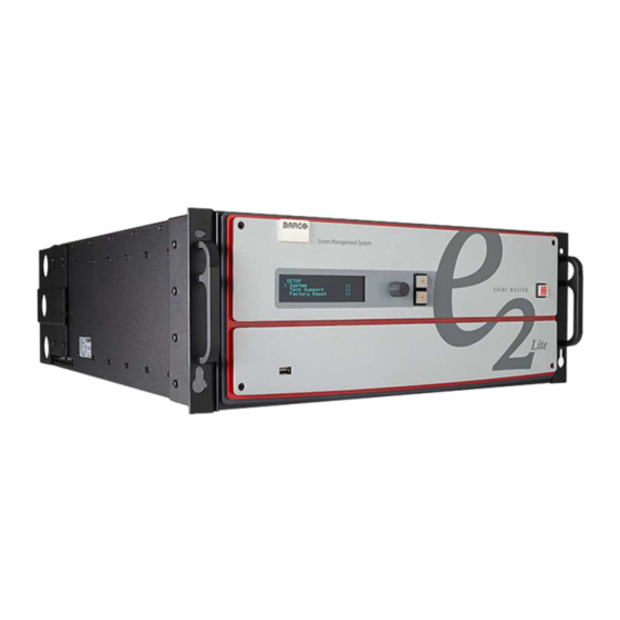
Page 34: Front Panel
Hardware orientation 4.1 Front panel About the front panel See Image 4-1 for an illustration of the front panel of the Event Master E2 Lite video processor. Image 4-1: E2 Lite front panel Barco logo Power ON/OFF button Display screen... -
Page 35: Rear Panel
The USB port is provided to support uploading and downloading system configurations and upgrading Event Master series processors firmware. 4.2 Rear panel About the rear panel See Image 4-4 for an illustration of the rear panel of the Event Master E2 Lite video processor. R5909934 /00 E2 Lite and EC-40... - Page 36 Genlock Input BNC with passive Loop-through AC connectors The Event Master E2 Lite is equipped with two redundant power supplies. During normal operation the load is shared equally by both supplies. If one supply fails, the second carries the whole load. Two AC connectors are provided to connect the E2 Lite video processor to your facility’s AC power source through the supplied power...
- Page 37 (with the second generation Tri-Combo Input card). Outputs cards The Event Master E2 Lite video processor supports HDMI output cards. Each output card supports resolutions of up to 1920x1200. On an E2 Lite processor, slots 11 through 13 are reserved for output cards.
-
Page 38: Dual Link Dvi Input Card
Hardware orientation 4.3 Dual link DVI input card General The dual link DVI input card includes two DVI-I dual-link connectors that can support a single or dual-link DVI video signal. Although the DVI-I connectors includes pins that support analog signals, the DVI card doesn't support analog signals. -
Page 39: Hdmi/Displayport Input Card
Hardware orientation ◦ 3,840x2,160/ 50/59.94/60 input via 2x DVIDL (L and R half) or 4x DVISL (quadrants) ◦ 4,096x2,160/ 23.98/24/25/29.97/30 input via 2x DVISL (L and R half) or 4x DVISL (quadrants) ◦ 4,096x2,160/ 50/59.94/60 input via 2x DVIDL (L and R half) or 4x DVISL (quadrants) ◦... -
Page 40: Tri-Combo Input Card
Hardware orientation Features • Process up to 4 signals independently • 2x 19–pin HDMI connector (Type A) • 2x 20–pin DisplayPort connector • Each input channel includes an LED that turns green when a valid sync is detected. HDMI specifications •... - Page 41 Hardware orientation Image 4-7: Tri-Combo Input Card Rear Panel DP connector — with an LED that turns on green when a valid sync has been detected HDMI connector — with an LED that turns on green when a valid sync has been detected BNC connector —...
- Page 42 Hardware orientation • Multi-Stream Transport (MST)—not supported • EDID version 1.3 compatible • HDCP version 1.3 compatible HDMI • HDMI per 2.0 specification • Pixel clock up to 600 MHz Max pixel clock at 24 bits/pixel = 600 Mpix/sec Max pixel clock at 30 bits/pixel = 480 Mpix/sec Max pixel clock at 36 bits/pixel = 400 Mpix/sec •...
-
Page 43: Hdmi Output Card
Hardware orientation 4K / UHD SMPTE 424M Image mapping: Quadrants SMPTE 2048-2 3840x2160 @ 50/59.94/60 as 4x 3G-SDI 4096x2160 @ 50/59.94/60 60 as 4x 3G-SDI Level A and B supported 4K / UHD SMPTE ST 425-5 Image mapping: 2 Sample Interleave Subdivision (2SI) 3840x2160 @ 23.98/24/25/29.97/30 as 4x HD- 4096x2160 @ 23.98/24/25/29.97/30 as 4x HD-... -
Page 44: Vpu Card
Hardware orientation Image 4-8: HDMI Output Card Rear Panel HDMI connector — HDMI 1 HDMI connector — HDMI 2 HDMI connector — HDMI 3 HDMI connector — HDMI 4 Features • Provide up to 4 independent signals • 4x 19–pin HDMI connector (Type A) Specifications •... - Page 45 Hardware orientation Mixing Layer Type Maximum number of Single Layers/Mixing Layers 2K HD 32/16 Dual Link 16/8 The VPU cards are not accessible from the rear panel on the E2 Lite unit. R5909934 /00 E2 Lite and EC-40...
- Page 46 Hardware orientation R5909934 /00 E2 Lite and EC-40...
-
Page 47: Front Panel Menu Orientation
About this chapter This chapter describes the front panel menus of the Event Master E2 Lite processor, including how they are accessed and the functions or parameters that are available. The menu trees are presented in block diagram format throughout the chapter. -
Page 48: Power-Up Initialization
Front Panel Menu orientation 5.1 Power-up initialization Initialization Ensure that your system is properly installed and cabled. Make sure the two AC Connector are properly connected to your facility’s AC power source through the two supplied power cords. Locate the power button on the front panel and turn power On. -
Page 49: Using Menu System
Front Panel Menu orientation Menu tree Image 5-2 5.3 Using menu system General This section describes the conventions for using the menu system of the Event Master devices. For reference, the following illustration shows the System Menu. R5909934 /00 E2 Lite and EC-40... - Page 50 Front Panel Menu orientation Image 5-3: System menu The unit’s display screen is four lines high. Throughout this chapter, entire menus are shown for ease of reference, unless otherwise noted. Please note the following important menu rules and conventions: • The top line names the current menu, in upper-case letters.
- Page 51 Front Panel Menu orientation Answering a menu query The SEL button is used to answer Yes to certain menu queries. The ESC button is used to answer No to menu queries. Sometimes the two buttons are appropriate to answer menu queries. The following illustration shows an example of a menu query.
-
Page 52: About Status Menu
Front Panel Menu orientation 5.4 About Status menu General The Status Menu is the Event Master series processor’s top-level menu, which appears by default at system startup. This menu provides system name, Unit ID, Genlock status and unit IP address. The following figure illustrates a sample Status Menu. -
Page 53: About The System Menu
Front Panel Menu orientation Image 5-7: Setup menu From the Setup menu, you can configure certain system settings for the Event Master unit, display Technical Support contact information, restore factory default settings, and check for available firmware updates. And finally, you can save all the recent changes to the system. The following sections describe each Setup Menu option in detail, except for the Code Upgrade feature. -
Page 54: System Menu > Usb Device (Backup/Restore)
Front Panel Menu orientation 5.8 System menu > USB device (Backup/Restore) General The unit's front panel contains a USB port that you can use to connect a flash drive to the Event Master unit. The flash drive must be formatted to use the FAT32 file system. For formatting instructions, refer to section Formatting the flash drive in the section “Upgrading firmware using the USB port”, page 196. - Page 55 Press the Save icon (the floppy disk icon in the lower left-hand corner of the screen). Copy the XML file to the USB device: Open Windows File Explorer. Locate and select the Barco folder on your C: drive. R5909934 /00 E2 Lite and EC-40...
- Page 56 Front Panel Menu orientation Image 5-13 Locate in the Barco folder and select the Event Master Toolset folder that corresponds to the current version you are using. Image 5-14 Select the wvp_9876 subfolder. Image 5-15 Open the xml folder. Image 5-16 The xml folder contains subfolders for presets, stills, and userkeys, and it contains the configuration settings file for your simulated system.
-
Page 57: System Menu > Ethernet
Front Panel Menu orientation Rename the settings.xml file to settings_backup.xml. Make sure that you do not change the file extension. Copy and paste the entire EM folder from your desktop to the root directory of a FAT32-formatted USB drive. Import the simulated configuration created offline to the live system: Insert the USB drive into the USB port on the front of a live Event Master processor. -
Page 58: System Menu > Vfd Brightness (Display Brightness)
Front Panel Menu orientation Setting a static IP Address When a DHCP server is not available, you can set the Event Master unit’s IP address, using the Set IP submenu shown in the following illustration. Image 5-18: Set IP Submenu (sample) How to set a static IP address? Ensure that the DHCP setting is Off. - Page 59 Front Panel Menu orientation Image 5-19 The Diagnostics options allow a user to check if the Event Master unit is functioning normally. Front panel and card operations can be checked. Various system temperatures can be monitored and backup log files can be saved for customer service troubleshooting.
- Page 60 Front Panel Menu orientation Cards Image 5-21 The Card Slot test will perform a variety of diagnostics for an individual card or for all cards. This is a quick way to determine if a given card is having a problem. After selecting a Slot number or choosing All cards to be tested, the following message will be displayed.
- Page 61 Front Panel Menu orientation If a slot is not populated with a card, the result will show EMPTY. Temperature Image 5-26 The DIAGNOSTIC TEMPERATURE menu will show real time measurements for the System, Motherboard and all card slots. All temperatures are shown in degrees Celsius. FPGA temperatures may reach as high as 85°C under normal operating conditions.
-
Page 62: System Menu > Lock Front Panel
The US Customer Support telephone number. This number is accessible from 6 a.m. to 10 p.m. (PST), 7 days per week. The European customer support number is: 0800-90-0410. In China call: 40088-22726. All other regions, call your local Barco support. •... -
Page 63: Firmware Upgrade
Front Panel Menu orientation Image 5-31 The following attributes constitute a factory default condition: • The Status Menu is shown in the display screen. • All custom configurations are deleted. The Factory Reset Menu provides two options for restoring factory default settings: •... -
Page 64: Save All
Front Panel Menu orientation Please refer to the chapter “Settings Menu”, page 162 for the instructions on how to perform firmware upgrades through the USB memory or the web interface. 5.16 Save All General Save All on the Setup menu saves your custom configuration parameters in non-volatile memory. If you save the system state, these parameters are restored the next time you power up the Event Master unit. -
Page 65: Em Gui Orientation
Multiviewer and manage system functions. Some screenshots and descriptions provided in this chapter may not accurately reflect the released software. Barco will update the documentation in a timely manner to mirror the released software. Overview •... - Page 66 EM GUI orientation • Programming Menu > Layer Modifier area • Programming Menu > Adjustment area • Programming Menu > Adjustment area > Layer configuration • Programming Menu > Adjustment area > Background configuration • Programming Menu > Adjustment area > User Keys configuration •...
-
Page 67: General Requirements
Fixed Ethernet connection 1Gb 6.2 Download of Event Master Toolset Software Overview The Event Master Toolset Software can be downloaded for free from Barco’s website, (URL: http://www.barco.com). The E2 Lite works only with the EMTS version 6.4. The software is also available on myBarco, with login to get access to secured information. Registration is necessary. -
Page 68: Software Installation
Currently the EM GUI is available for PCs with Microsoft Win7 or Microsoft Win10, and Apple MACs with OS X. The software will run on other Microsoft and Mac operating systems, but currently Barco only supports software installations with Win7 (or Win10) and OS X computers. Linux version of the software will be available in a future release. - Page 69 EM GUI orientation Image 6-1: GUI orientation Menu navigation bar Title bar Selection area Diagram area Modifier area Configuration area Menu navigation bar On the far left hand side of the screen is the Menu Navigation bar that allows users to navigate between the different screens and save or restore system configurations.
-
Page 70: Controls
EM GUI orientation Configuration area On the right hand side, is the configuration area where users perform all needed adjustments. 6.6 Controls Edit box Edit box is used to edit the values or names. Image 6-2 Properties: • By double clicking, the background changes to a dark blue color indicating that modifications can be made. •... -
Page 71: Configuration Menu
EM GUI orientation 6.7 Configuration Menu General The Configuration menu is the module used to edit the Presentation Systems (creation, modification, deletion). This page is the first page that appears when you launch the EM GUI software. The user will use this page to add or remove devices to the selected system. The user also could modify the parameters of these devices such as inputs, outputs, and destinations. -
Page 72: Configuration Menu > Network Resource Area
EM GUI orientation System modifier area System information is displayed in this area. To view a different system you select the corresponding tab from the top. This area also includes Workspace related tools. Adjustment area There are several panels in this area: Adjustment, Input/Background, Output/MVR and Destinations. - Page 73 EM GUI orientation Description The panel in this area has three tabs: • Discovered: Lists all of the devices discovered on the local network, regardless of the selected System. • In use: Lists the devices in the selected System. Note: When the Discovered tab is selected, the Event Master ToolSet Software will continuously send a UDP broadcast over the network to locate devices (every 5 seconds).
-
Page 74: Configuration Menu > System Diagram Area
EM GUI orientation Image 6-7: Drag and drop a device into the selected system How to manually add a device into the selected system To manually add a device, use the “Manual Add” section. Enter the IP address. Press the “Add” button. Image 6-8 Unit is added and retrieves the available configuration in the Device. - Page 75 EM GUI orientation Image 6-9: System diagram area In this area, the rear panel of the selected system is represented graphically with the cards, and the connectors are color coded to indicate their status. The color code is: • White = Connector available to add and configure. •...
- Page 76 EM GUI orientation Image 6-10 A confirmation window appears. Click on OK. The tab is removed. How to select device in the system Click on the area situated below the Event Master series processor graphic representation. Image 6-11: Device selected The device is selected.
-
Page 77: Configuration Menu > System Modifier Area
EM GUI orientation Image 6-12: Destination selected The destination is selected. The destination is highlighted in blue. Selecting a device or a destination in the Diagram allows the Adjustment area to display to display the parameters corresponding to the device or destination. See Adjust Tab in the section “Configuration Menu >... -
Page 78: Configuration Menu > Adjustment Area
EM GUI orientation • System Native Rate (Hz): System native rate in Hz (Cycles in second). Available selections: 59.94 The native system rate needs to match the general frame rate in the event where the unit is used. • System Backup: IP address of the backup system. Enter the IP address of the backup unit, and press the "Sync"... -
Page 79: Configuration Menu > Adjustment > Unit Configuration
EM GUI orientation • “Configuration Menu > Adjustment > Input Configuration”, page 83 • “Configuration Menu > Adjustment > Output Configuration”, page 91 • “Configuration Menu > Adjustment > Destination Configuration”, page 97 6.12 Configuration Menu > Adjustment > Unit Configuration General In the unit configuration adjustments panel, the user can define and adjust unit (device) specific parameters. - Page 80 EM GUI orientation Description Settings tab: • Name: The name of the unit can be edited here. • Contact info: User information for contact person responsible for the unit. • SW Version: Unit’s Firmware version. • OS Version: Unit’s OS version. Note: The EM GUI has its Software version shown in the Settings Page.
- Page 81 EM GUI orientation Setup tab: • Unit ID: Unique unit identification number. • Front Panel: Locks or unlocks the front panel. • Front Panel VFD Brightness: Updates the brightness of the front panel VFD. • Black on invalid video: If checked, when the input timing on the video does not match what was previously acquired on the input connector the video will be set to black.
- Page 82 EM GUI orientation The Status tab shows the name, temperature, and fan status of the motherboard and each card slot. Last slot as MVR or Output in the simulator To toggle between using the last slot on the simulator as an Output or as an MVR... Check the "Last slot as MVR"...
-
Page 83: Configuration Menu > Adjustment > Input Configuration
EM GUI orientation 6.13 Configuration Menu > Adjustment > Input Configuration General In the Input configuration menu users can assign input connectors to inputs and adjust parameters to match the incoming signal format and timing parameters. Input Card arrangement On the E2 Lite model, the input cards occupy slots 3 through 10 and are right justified to slot 10. If there is an empty input slot between two input slots, all input cards to the left of the empty slot are marked with red. - Page 84 EM GUI orientation Input connector colors Not assigned and no input signal is detected Not assigned to any Source or an input, but a signal has been detected Assigned to a source or an input and an input signal is detected Assigned to a source or an input, but an input signal is not detected Input configuration menu description Input configuration menu is accessed by clicking on the Input tab.
- Page 85 EM GUI orientation as “Input 1, 2, 3….”. Input configuration names can be renamed by double-clicking on the name and turning the box blue. Image 6-15: Configuration menu, Adjustment area, Input The auto add feature adds only up to 2K resolution inputs. 4K Inputs need to be assigned manually. See How to add Input section below.
- Page 86 EM GUI orientation Multiple connector configurations can be selected to be deleted together. How to access to the Input configuration adjustments Adjustments to inputs are performed in the “Adjust” panel: Select the input from the configuration list clicking on the connector graphic. An input is selected.
- Page 87 EM GUI orientation Input adjustment panel > Main page This menu is available in two versions according to the input type: • DVI, HDMI and DisplayPort input types • Name: Edits the name of the input configuration. • Sync Status: Detects a good video sync. •...
- Page 88 EM GUI orientation All inputs can have an EDID (Extended Display Identification Data) set according to its connector capacity. The currently set EDID is visible in the Current box. Format: The drop-down menu with its search function provide a way to select any of the available VESA or SMPTE standard EDIDs as well as a frame rate.
- Page 89 EM GUI orientation Please note the following important points regarding In Auto Acquire: • It is recommended that you turn Off Auto Acquire in applications where you have already configured and saved the system’s input setup. • If Auto Acquire is On and a valid input is selected that does not have a saved input associated with it, the system attempts to detect and acquire the source.
- Page 90 EM GUI orientation Input adjustment panel > Color Adjustment This menu allows for color adjustments for each input. • The RGB Contrast and Brightness settings are adjustable. The Overall adjustment has a range of 50 to 150. The individual Red/Green/Blue adjustments have a range of 25 to 150.
-
Page 91: Configuration Menu > Adjustment > Background Configuration
EM GUI orientation 6.14 Configuration Menu > Adjustment > Background Configuration General Because the E2 Lite uses only Stills and mattes as backgrounds, the Background configuration controls are disabled. Image 6-17: Background configuration disabled 6.15 Configuration Menu > Adjustment > Output Configuration General In the Output menu users can assign output connectors to configurations and adjust signal parameters to... - Page 92 EM GUI orientation If the card with the connectors that are part of an output configuration is missing, the card in the unit graphic and the output configuration in the configuration list will be grayed out. Also, if there is an existing output configuration but the card in the slot is of different type, then again the configuration will be greyed out.
- Page 93 EM GUI orientation Image 6-19: Configuration menu, Adjustment area, Output The unit will query the connected device on its output for a preferred EDID and try to assign that as the output resolution and frame rate. If no devices are connected, a standard HD resolution with the native rate of the EMP is assigned as frame rate.
- Page 94 EM GUI orientation You can only delete Output Configurations that are not assigned in Destinations. How to access to the output configuration adjustments Adjustments to outputs are performed in the “Adjust” panel: Select the output from the configuration list clicking on the connector graphic. An output is selected.
- Page 95 EM GUI orientation Output adjustment panel > Main page • Auto Configure Output format: Selects the output format will be set to match the format contained in the EDID of the display device connected to the corresponding output(s). • Name: The name of the output configuration can be edited in this field.
- Page 96 EM GUI orientation Output adjustment panel > Timing Menu • Format: Selects the video format of the output configuration from the drop menu. This is the same adjustment as in the previous menu. • H Total: Adjusts (in pixels) the total pixel count per line for the selected output.
-
Page 97: Configuration Menu > Adjustment > Destination Configuration
EM GUI orientation The selection of HD (1080i) or 3G SDI (1080p) actually happens when the format type is selected in the main tab. 6.16 Configuration Menu > Adjustment > Destination Configuration General Output configurations that are created in the previous menus are assigned to destination in the Destination Panel. - Page 98 EM GUI orientation Destination formats A few words about destination formats: • For Screen Destinations: The format of any Output configuration added to a Screen Destination is updated to match the format of the Screen Destination. If the first Output configuration in a Screen Destination is deleted and a new Output configuration is added, then the format of the new Output configuration becomes the format of the Screen Destination.
- Page 99 EM GUI orientation Image 6-21: Assign Screen and Aux Destinations Manipulating Screen Destinations in the Programming Menu Use the Programming menu to manipulate Screen Destinations. Image 6-22: Screen and Aux Destinations on the Programming Menu AOI markers “Off” Aux Destination 1 Screen Destination 1 Resources area Screen Destination 2...
-
Page 100: Configuration Menu > Adjustment > Destination Configuration > Adjust Panel
EM GUI orientation buttons align the Layer into the Screen Destination in which the center of the Layer is located. With the AOI Markers set to "Off," the Layer alignment buttons align the Layer in the entire Screen Destination. Drag and drop Inputs from the Resources area to desired Destinations. Apply system-wide functions, User Keys, or Presets to Layers in the Screen Destinations. - Page 101 EM GUI orientation Image 6-23: Add destination buttons If the Add destination button is pressed without selecting an output configuration, the software will automatically assign the first unassigned output configuration (from left most output card) to a destination. The output configuration format is copied to the destination output format. New Screen or Aux destinations can be added as long as there are unassigned output configurations to destinations.
- Page 102 EM GUI orientation How to delete Destination Click on the Delete Destination(s) button The Delete Destination(s) button is replaced by the Delete Selected button (highlighted in red) and the unit diagram is greyed out, except the area dedicated to destinations (Screen and Aux).
- Page 103 EM GUI orientation Image 6-26: Destination Adjust tab The Destination adjustment panel is displayed. Destination adjustment panel description The Destination adjustment panel is divided in three sections: • Assign • Output • Wide R5909934 /00 E2 Lite and EC-40...
- Page 104 EM GUI orientation Assign Menu • Name: Adjusts the name of the Destination. • Destination type: Reports the type of destination Screen or Aux. Can convert from Screen to Aux if it meets requirements. • Number of output(s): Reports the number of output configurations in the destination.
- Page 105 EM GUI orientation ◦ Minimum delay capable Screen Destinations that are rotated have 1 frame of delay. ◦ Non-minimum delay capable Screen Destinations that are rotated have 2 frames of delay. ◦ AUX Destinations have 1 frame of delay. ◦ Rotated AUX Destinations have 2 frames of delay.
- Page 106 EM GUI orientation Image 6-27: Configuration Menu: Destination Adjust—Output (Top of panel) Main Color Timing Connector properties R5909934 /00 E2 Lite and EC-40...
- Page 107 EM GUI orientation Output menu – Main submenu Operate similarly to the Output adjustment panel > Main menu. • Test pattern: Turns the Test Patterns ON and select the desired type. The default setting is OFF. Test pattern types: – Horizontal Ramp –...
- Page 108 EM GUI orientation Output menu – Color submenu The Output Effects Submenu adjusts color variable of the output image, such as contrast and brightness, saturation, hue and gamma corrections. • The RGB Contrast and Brightness settings are adjustable. The Overall adjustment has a range of 50 to 150.
- Page 109 EM GUI orientation Output menu – Timing submenu Operate similarly to the Output adjustment panel > Timing menu. • Format: Selects the video format of the output configuration from the drop menu. This is the same adjustment as in the previous menu. •...
- Page 110 EM GUI orientation HDMI Connector submenu • Color/Sample/Bit: Choices are: – RGB/4:4:4/8 – YCbCr/4:4:4/8 – RGB/4:4:4/10 – YCbCr/4:4:4/10 – RGB/4:4:4/12 – YCbCr/4:4:4/12 – YCbCr/4:2:2/12 • Color Range: Choices are: RGB, Reduced Range (Values 16–235, television and movies) RGB, Full Range (Values 0–255, computer monitors) SMPTE, Full Range SMPTE, Reduced Range...
- Page 111 EM GUI orientation Data-doubling submenu—Basic Mode • Canvas H: This is the horizontal size of the canvas, measured in pixels. The edit box allows the user to adjust this size. • Canvas V: This is the vertical size of the canvas, measured in pixels.
- Page 112 EM GUI orientation Data-doubling submenu—Expert Mode The top part of the panel is the same in Expert Mode as it is in Basic Mode. Expert Mode, however, offers greater control over horizontal and vertical Offset and Size. Expert Mode also allows the user to add Outputs without increasing the canvas size and to place those Outputs anywhere within the canvas.
-
Page 113: Configuration Menu > Linking
EM GUI orientation Feathering submenu • Canvas shows the actual pixel ratio for the full blend. • Select the region where feathering will be performed. All edges can be separately selected and have a different value of Feather and Gamma. The adjustment can be made my moving the slider, entering the value manually in the box or click on the plus and minus. - Page 114 EM GUI orientation After linking chassis, a few menus provide the option of changing between which unit controls you are viewing. From the Menu bar at the top of all pages, you can select which processor’s details you are viewing, by selecting that processor from the pull down menu.
- Page 115 1294: Cable and Connector Damage on the Link Cards for E2 Series and S3– 4K Series Presentation Switchers” on the Technical Downloads tab on the E2 Full-sized Event Master processor web page (URL: https://www. barco. com/en/Products/Image-processing/Presentation-switchers/Full-sized-Event-Master- processor.aspx?#!downloads). For more information on Event Master Link-Cable solutions, see “InfoT-1413: Event Master series link-cable solutions for E2, S3–...
-
Page 116: Programming Menu
EM GUI orientation Always check for updated information that may have come out since this manual was published and for the latest version of all documents on www.barco.com. 6.19 Programming Menu General The programming page is where the event is set up and everything comes together. Users can define sources from inputs, assign layers and backgrounds into screens and create User keys and presets and more. -
Page 117: Programming Menu > Resources Area
EM GUI orientation The following sections describe each part of the Programming page in detail: • “Programming Menu > Resources area”, page 117 • “Programming Menu > Diagram area”, page 127 • “Programming Menu > Layer Modifier area”, page 130 •... - Page 118 EM GUI orientation Layer • Definition: A layer is one image stacked on top of another or a background. • Features: Each mixer layer has two layers, Preview and Program. For complete flexibility, each layer can be assigned to either PIP or Key functionality. Image 6-30 The mixing Background layer (BG) has the lowest priority.
- Page 119 EM GUI orientation Inputs (List view) Inputs (List view) • Resolution: This is the resolution of the Input signal. • The LED color indicates the status of the input: Red: Sync is missing or invalid format. Green: Sync is valid. •...
- Page 120 EM GUI orientation Inputs (Thumbnail view) • Behavior is similar to the List View mode (see above). By clicking in thumbnail area images can be imported using the file picker menu. The picker can select pictures with the BMP, JPG or PNG format. R5909934 /00 E2 Lite and EC-40...
- Page 121 EM GUI orientation Stills (List view) Stills (List view) • Stills can be added from external source of the GUI computer in the PNG format. A PNG with a transparency is marked in the Stills list with a (T). • Name that can be changed by double click action and then the resolution of the Stillstore.
- Page 122 EM GUI orientation Stills (Thumbnail view) • Behavior is similar to the List View mode (see above). By clicking in thumbnail area images can be imported using the file picker menu. The picker can select pictures with the BMP, JPG or PNG format. R5909934 /00 E2 Lite and EC-40...
- Page 123 EM GUI orientation Destination Destination (List view) Destination (Thumbnail view) The Destinations can be used as a source in Layers provided they have the capacity to fit. Up to 2K resolutions on SL, up to 4096 x 1200 / 2560 x 1600 for DL and 4K / 8192 x 1200 for 4K Scaler Mode. How to delete sources The delete process is similar for all lists with more than one entry.
- Page 124 EM GUI orientation Image 6-31: Delete Selected Input sources Select the sources that you desire to delete and click the Delete Source(s) button. The selected sources are removed. How to hide Inputs As the inputs are usually named after its physical names while the sources are named after the Show Usage we allow to hide the inputs from the list: Check the Hide Inputs box.
- Page 125 EM GUI orientation Image 6-32: Hide Input(s) checkbox Background Stills In this menu, Background Stills captured in the Background Source menu are assigned to destinations via drag and drop procedure. Background Stills and Destinations need to have the same resolution including the Destinations eventual blend overlap.
- Page 126 EM GUI orientation Background Stills (List view) • Name: This is the Name of the Stillstore as created in Background menu. Name can be changed by double click action. • Resolution: This is the resolution of the Stillstore. • [Disk Icon] Indicates the memory required for the Stillstore.
-
Page 127: Programming Menu > Diagram Area
EM GUI orientation Background Stills (Thumbnail view) • Behavior is similar to the List View mode (see above). By clicking in thumbnail area images can be imported using the file picker menu. The picker can select pictures with the BMP, JPG or PNG format. 6.21 Programming Menu >... - Page 128 EM GUI orientation Image 6-33: Diagram Area of the Programming Menu Lock icon indicates whether the PGM destination is locked. When locked, the Program screen can only change after a Mix or Cut transition. When the program screen is unlocked, the user can click on a layer that is on PGM and move or resize it.
- Page 129 EM GUI orientation Next a source from the Input panel on the left hand side can be dragged into the layer. Image 6-35 Alternatively, an Input or a source can be dragged into the Preview screen directly as long as there are available layers.
-
Page 130: Programming Menu > Layer Modifier Area
EM GUI orientation Selected layers are highlighted with a blue border. Aux Destination Canvas Assigning inputs/sources to Aux destination works the same way as in the screen destinations within the constraints of the AUX destinations. Only one input can be assigned to each destination and it is always at full screen. - Page 131 EM GUI orientation Alignment Image 6-39: Alignment adjustments Align Left to align the left edges of all selected PIPs. Align Top to align the top edges of all selected PIPs. Align Right to align the right edges of all selected PIPs. Align Bottom to align the bottom edges of all selected PIPs.
- Page 132 EM GUI orientation Moves the selected layer up in priority and swaps with the layer previously above. Moves the selected layer to the top of the priority and swaps it with the layer previously on top. Moves down in priority and swaps the z-order of the selected layer with the layer previously below. Moves the selected layer to the bottom of the priority and swaps it with the layer previously at the bottom.
- Page 133 EM GUI orientation Resize example: Image 6-43 Match example: Image 6-44 Transition Image 6-45: Transition adjustments Rate(frame) is the rate in frames at which transitions from Preview to Program take place. Trans transitions Preview to Program according at the rate indicated in the rate box following the s- curve pattern.
- Page 134 EM GUI orientation Miscellaneous operations Image 6-47: Miscellaneous operations Freeze freezes the image that is displayed in the layer. The layer can still be positioned and sized within the destination. The text of a frozen layer turns blue and a “freeze” icon (snowflake) appears on the bottom right corner.
-
Page 135: Programming Menu > Adjustment Area
EM GUI orientation Select All selects all Layers in Preview. It is equivalent to left clicking on all unselected layers on Preview one at a time while Multiple Select is On. Unselect All unselects all Layers in Preview. It is equivalent left clicking on all selected layers on Preview one at a time while Multiple Select is On. - Page 136 EM GUI orientation This menu provide: • A list of the available destinations and the layers associated with that destination. • Swap Z order button that allows for layers that are in the same Destination and of the same type to be swapped.
- Page 137 EM GUI orientation Image 6-50 When the layer is selected and is visible on the canvas, it will have a blue highlight around the layer. Click on the Adjust tab that is on the top of the adjustment area. The layer adjustment panel is displayed. It is possible to select multiple layers by clicking on the each targeted layer once Multiple Select is set to ON.
- Page 138 EM GUI orientation • Borders are enabled by selecting the type of to apply. Note: Only hard borders are available on the E2 Lite processor. • Border width and color are selected by adjusting the corresponding sliders or entering a figure in the adjacent edit boxes.
- Page 139 EM GUI orientation Layer type = Key; Mode = Luma A Luma (Luminance) Key is one in which the hole- cutting information is derived from the luminance (brightness) level of the key source. Source on the Key Bus can be selected as the “cut.” You can select Self or Matte, Preset Bus or Split for the “fill”...
- Page 140 EM GUI orientation Layer type = Key; Mode = Chroma A Chroma (Chrominance) Key is one in which the hole-cutting information is derived from a color in the key source. After selecting a Hue color to key out, it may be necessary to make additional adjustments to improve the look of the overall compositing effect.
- Page 141 EM GUI orientation • Range: 0 to 100 • Default: 5 Saturation Gain: This defines the transition along the saturation axis between keying off and keying on. • Range: 0 to 100 • Default: 5 Reset:Press to return all clip, gain and opacity settings to their default values.
- Page 142 EM GUI orientation Layer adjustment panel > Layer Window adjustment The following PIP Adjustment Menu functions are provided: (All figures are in pixels) • H Size — adjusts the PIP’s horizontal size. • V Size — adjusts the PIP’s vertical size. •...
-
Page 143: Programming Menu > Adjustment Area > Background Configuration
EM GUI orientation Layer adjustment panel > Layer Effects adjustment • Layer Opacity: Adjusts the opacity of the layer. Opacity is adjustable within a range of 0 to 100. The default setting is 100. • Strobe: Toggles the strobe function on and off. When On, adjust the strobe Rate interval (in frames) to set the duration that the source is frozen until the next grab. - Page 144 EM GUI orientation Select the background from the preview windows. The layer is selected. Image 6-55: Select background layer from Preview window The background button will have a blue highlight when selected. Click on the Adjust tab that is on the top of the adjustment area. The background adjustment panel is displayed.
-
Page 145: Programming Menu > Adjustment Area > User Keys Configuration
EM GUI orientation The Standard color wheel selection is available for the Background Matte too • Background color can be adjusted by updating the Red / Green / Blue slider or edit box. The selected color is shown in the Current Color row. •... - Page 146 EM GUI orientation User Keys configuration menu description This menu provides: • A numbered list of the available User Keys. • A button to Save the attributes of a Layer as a new User Key. • A button to Overwrite the Layer data in the selected User Key.
- Page 147 EM GUI orientation Delete User Key(s) Allows for multiple deletes of User keys. Click the Delete UserKey(s) button. Select the User Key to be deleted by clicking the X next to the lock for that User Key. Image 6-56: Select a User Key Note: If a User Key is locked, it cannot be deleted.
-
Page 148: Programming Menu > Adjustment Area > Presets Configuration
EM GUI orientation 6.27 Programming Menu > Adjustment area > Presets configuration General The Preset is a register that enables you to store destination setups, “looks,” to memory, and to recall them. Presets configuration menu description This menu provides: • A numbered list of the available Presets. - Page 149 EM GUI orientation Save From PVW Saves the current look on Preview into a new Preset. Only Destinations that are active or selected will be saved. For example: There are 3 Destinations. User enables Dest1 and Dest 3 and presses “Save to new Preset.”...
-
Page 150: Programming Menu > Adjustment Area > Source Adjustment
EM GUI orientation 6.28 Programming Menu > Adjustment area > Source adjustment General The Source adjustments are shown on the Adjust panel when a layer with a valid Source is selected. The Source adjustment controls does not appear when you select the Source by itself. Also note that the adjustments made here are made on the layer’s copy of the Source, not the actual Source itself. -
Page 151: Programming Menu > Adjustment Area > Global Transition Rate/Trans/Cut
EM GUI orientation Color adjustment • RGB Contrast and Brightness settings are adjustable within a range of 0% to 200%. The default setting for all of these properties is 100%. • Gamma is adjustable within a range of 0.3 to 3.28. The default setting is 1.0. -
Page 152: Multiviewer (Mvr) Menu
EM GUI orientation This button transitions the Preview into Program according to the transition rate. The transition Rate is transition rate in frames of the native rate. Four transition types are available: Linear, S-Curve, Logarithmic and Exponential. Image 6-61: Available transition types CUT button Pressing the CUT button immediately presents the Preview to the Program. -
Page 153: Multiviewer Menu > Resource Area
EM GUI orientation Resources area Lists the resources available to be displayed in the Multiviewer: Inputs, Backgrounds and Program/Preview Destination Outputs. Multiviewer Layout area The two multiviewer outputs are composed, viewed and managed individually or as a group. Modifier area Alignment adjustments and controls to manage the multiviewer outputs Adjustment area... - Page 154 EM GUI orientation Description Image 6-63: Multiviewer Menu, Resource area There are 3 tabs in this section: • Input: Lists the inputs as defined in the System Configuration menu. • Background: Lists the backgrounds as defined in the System Configuration menu. •...
-
Page 155: Multiviewer Menu > Multiviewer Layout Area
EM GUI orientation Image 6-64: Add a resource to the Multiviewer Screen Destinations (Program and Preview) can be used up to two times in any Multiviewer Output. The position of the window for each copy can be different, but the size of the window for each copy is always be the same."... -
Page 156: Multiviewer Menu > Modifier Area
EM GUI orientation Multiviewer windows, also called Image windows, are composed from inputs, backgrounds and destination sources. There are 3 elements that make up a multiviewer image window: Content area, border and UMD (Under-Screen-Display). Image 6-67 Content area The default content display area has 16:9 aspect ratio. If the source dragged to this area has different aspect ratio, it will be adjusted horizontally to fit the space. - Page 157 EM GUI orientation Image 6-68: Window alignment controls Align Left to align the left edges of all selected PIPs. Align Top to align the top edges of all selected PIPs. Align Right to align the right edges of all selected PIPs. Align Bottom to align the bottom edges of all selected PIPs.
- Page 158 EM GUI orientation Clear removes the selected window from the multiviewer window. Auto Layout Input clears the multiviewer display and places all selected sources and the background from the list in the multiviewer display in the arrangement shown in Image 6-70. UMD: On/Off toggles the UMD (under-screen-display) of selected windows on and off.
-
Page 159: Multiviewer Menu > Adjustment Area
EM GUI orientation 6.34 Multiviewer Menu > Adjustment area General Situated on the right hand side of the screen is the Adjustment area. In this area the user can configure the color and sizing of each multiviewer windows. Description There are several tabs in this area: •... -
Page 160: Multiviewer Menu > Adjustment Area > Window Adjustment
EM GUI orientation • The selected color is shown in the Current Color bar. The color can also be stored by clicking in one of the square boxes at the bottom of the menu next to the Learn button. These boxes are quick shortcuts to select that color. -
Page 161: Controller Menu
EM GUI orientation Description The following functions are provided: • H Size(pixel): Adjusts the window’s horizontal size in pixels. • V Size(pixel): Adjusts the window’s vertical size in pixels. • H Pos(pixel): Adjusts the window’s horizontal position in pixels. • V Pos(pixel): Adjusts the window’s vertical position in pixels. -
Page 162: Settings Menu
EM GUI orientation Description Image 6-72: Controller Menu Overview Resources area Virtual representation of the selected controller This menu is accessible by clicking the Controller icon in the menu bar on the left side of the UI. The Controller setup page is divided in two parts. One list of available resources (right side of the page) and one virtual representation of the selected controller. - Page 163 EC-30 settings and is applicable only when an EC-50 / EC-40 / EC-30 controller is connected on the network. • The Devices tabs shows what Barco devices (such as projectors) are detected on the network. • The Option tab allows the user to choose settings concerning the Event Master Toolset Software.
- Page 164 EM GUI orientation Description of the Options tab of the Resources area • Language: This parameter allows the user to choose the language of the GUI. Note: The only language available in version 1.5 is English. • Version Number: version number of the Event Master Toolset (read only). •...
- Page 165 EM GUI orientation Software subtab This panel displays the serial number and the software version for each detected controller. When the Controller > Software subtab is selected in the Resources area, the Web App area shows the EC- 200/EC-210 web app. The user can upgrade the EC- 200/EC-210 software through the EC-200/EC-210 web app.
- Page 166 EM GUI orientation Diagnostic subtab This panel displays test controls for each detected controller. • LED Test: Test Off: LEDs are returned to normal behavior. All Blue/Red: Turns on all blue and red LEDs; other LEDs are turned off. All Green: Turns on all green LEDs; other LEDs are turned off.
- Page 167 EM GUI orientation Image 6-76: Devices tab Dragging and dropping any discovered device from the Resources area to the Web App area hosts the device (for example, an ImagePro II) in the Web App area. Image 6-77: Devices list R5909934 /00 E2 Lite and EC-40...
- Page 168 EM GUI orientation R5909934 /00 E2 Lite and EC-40...
-
Page 169: System Setup
System Setup About this chapter This chapter outlines procedures for setting up and configuring Event Master series processors. CAUTION: Before starting to set up your Event Master series processor, please ensure that you are familiar with front panel menus and Event Master Toolset Software. Overview •... -
Page 170: Setup Prerequisites
System Setup 7.1 Setup Prerequisites Prerequisites Before starting to set up your Event Master series processor, please review the following prerequisites: • Ensure that you are familiar with the Event Master devices, including system control means and features. For details, please refer to Chapter “General”, page 19. •... -
Page 171: Power Up And Status Check
System Setup Configuration Menu > Layer optimization. For more information see section “Configuration Menu > Layer optimization”, page 183. Configuring Menu > Add Aux Destinations. For more information see section “Configuration Menu > Add Aux Destinations”, page 184. Configuring Menu > Add MVR Outputs. For more information see section “Configuration Menu > Add MVR Outputs”, page 186. -
Page 172: Return To Factory Default
System Setup check all Ethernet connections. After checking connections, if devices still report “Not Connected,” use the procedure “Communication setup”, page 172. 7.4 Return to factory default General Prior to performing any setup procedures, it is recommended that you perform a factory reset — in order to reset all input, output and source mappings to their default values. -
Page 173: Restoring The System
System Setup Define the Ethernet settings to remotely access is mandatory to control the Event Master series processor via the Event Master Toolset Software or via a web interface. Please contact the manager of the local network (LAN) to know how configuring your device. Query the DHCP server Select Ethernet from the System Menu. -
Page 174: User Preference Setup
System Setup You must reboot the system to use the restored configuration file. At the conclusion of this procedure, your system is completely set up — exactly the way that you left it when you performed a complete system “backup.” No further setup operations are required. 7.7 User preference setup General This procedure enables you to set a variety of important user preferences and options. -
Page 175: Configuration Menu > Initial Setup
System Setup Prerequisite • Ensure that you are familiar with the USB device (Backup/Restore) Menu. For details on this menu, please refer to chapter “System menu > USB device (Backup/Restore)”, page 54. Restore a system configuration file Use the following steps to restore your system from the USB Drive: Insert a formatted flash drive in the unit’s front-panel USB port. -
Page 176: Configuration Menu > Add Inputs
System Setup 7.11 Configuration Menu > Add Inputs General In this procedure, you will add Inputs to the system. The system must have inputs added in order for them to be available. Prerequisite • Ensure that you are familiar with the Configuration Menu. For details on this menu, please refer to chapter “Configuration Menu”, page 71 If more than one Input is utilized, repeat the below steps until all Inputs are added and adjusted. -
Page 177: Configuration Menu > Add Outputs
System Setup Select color space, capacity and type (for SDI inputs). Perform color adjustments. Read all timing parameters associated with the selected format. (Optional) Delete Inputs Click on the blue button Delete Input(s). From the Name list click on the “x” space next to the Input(s) you wish to delete. Or select connectors. Hit the red button Delete Input(s) button. - Page 178 System Setup (Optional) Delete Outputs Click on the blue button Delete Output(s). From the Name list click on the “x” space next to the Output(s) you wish to delete. Or select the connector. Hit the red button Delete Output(s) button. All of the selected Outputs will be removed from the list. (Optional) Adjust Output Parameters Click on the Adjust tab that is located on the top.
- Page 179 System Setup Image 7-2: Adjust MVR panel—Timing [Connector tab] Select SDI type and Sync standards. [Connector tab] Select Color space and Sample bit depth available as reported from the EDID of the Device. [Connector tab] Change Connector capacity as long as the connector is not included in a Destination. [Connector tab] Select HDCP Mode On or Off.
-
Page 180: Configuration Menu > Add Screen Destinations & Layers
System Setup Image 7-3: Adjust MVR panel—Connector 7.13 Configuration Menu > Add Screen Destinations & Layers General In this procedure, you will Add Screen Destinations from the defined outputs. Prerequisite • Ensure that you are familiar with the Configuration Menu. For details on this menu, please refer to chapter “Configuration Menu”, page 71 If more than one Destination is utilized, repeat the below steps until all Destinations are added. - Page 181 System Setup If you need to delete layers, click on the Blue button Delete layers. (Optional) Edit the Name Double click on “Destination1” in the Name list to edit the name. When the area turns blue, click the eraser icon to clear the field. Type a new name and hit enter when done.
- Page 182 System Setup (Optional) Adjust Destination Parameters part 3 > Wide Tab From this menu you choose between the two sub tabs: • Data Double, where you can adjust data doubling parameters based on the selection done in the window below. Image 7-4 •...
-
Page 183: Configuration Menu > Layer Optimization
System Setup Image 7-5 (Optional) Delete Destinations Click on the blue button Delete Destination(s). From the Name list click on the “x” space next to the output(s) you wish to delete. Hit the red button Delete Destination(s) button. All of the selected Destination(s) will be removed from the list. 7.14 Configuration Menu >... -
Page 184: Configuration Menu > Add Aux Destinations
System Setup Here is an important difference from other systems, an EMP only scales the number of available layers based on the inputs size, not the output size as long we are inside a maximum of a 4K or 10MP output. Once passed the 10MP (MegaPixel), resources have to be added. - Page 185 System Setup Each of the settings will allow for different size input / still and destination sources from the Input Resource tab covered in the Programming Section below. DL = Max 2560 x 1600 or 4095 x 1200 4K = Max 4096 x 2400 or 8192 x 1200 8L = Max 8192 x 2400 or 16384 x 1200 (Optional) Adjust Destination Parameters part 2 >...
-
Page 186: Configuration Menu > Add Mvr Outputs
System Setup 7.16 Configuration Menu > Add MVR Outputs General In this procedure, you will add MVR Outputs to the system. Prerequisite • Ensure that you are familiar with the Configuration Menu. For details on this menu, please refer to chapter “Configuration Menu”, page 71 Add MVR Output Click on the MVR tab to select the outputs that will be defined. -
Page 187: Programming Menu > Capture Stillstore From Inputs
System Setup Image 7-6: Adjust tab: Connector Settings subtab Only a few formats are available for the MVR Outputs as it is not a Program Output Only Destinations with the same frame rate will be possible to add to the MVR output. More details on this topic in the Help File in your Event Master Processor. -
Page 188: Programming Menu > Select Thumbnails For Inputs
System Setup Capacities and limitations As a reference approximately 50 HD or 12 UHD stills can be stored, if the size of the still is bigger, the memory allocation increases allowing for less number of stills. Image can be imported as described in the Operation Section below. -
Page 189: Programming Menu > Drop Backgrounds Into Screen Destinations
System Setup Image 7-9 Click on the arrow next the Input name. To copy the raw original source file click on the PLUS in the Input. To copy the source click on the copy icon. This creates a copy of the Source including changes made and saved. - Page 190 System Setup Prerequisite • Ensure that you are familiar with the Programming Menu. For details on this menu, please refer to chapter “Programming Menu”, page 116. Drop Sources into Screen Destinations From the top of the Resource Pane to the left select INPUT. Choose from the available Source types: Input Stills Destination...
-
Page 191: Programming Menu > Drop Inputs To Aux Destinations
System Setup Adjust Mask of the layer. This has in the past been called crop. (Optional) Adjust Layer Parameters > Layer Effects submenu With the Layer Effects submenu you can: Activate and Adjust Strobe effect for the layer. Activate and Adjust Flip effect for the layer. Activate Freeze effect for the layer. - Page 192 System Setup (Optional) User Keys Click on the Adjust tab that is located on the top. Click on the User Keys tab. To create a user key, first select the layer parameters you wish to save to a user key: Type, transition, Effects, Border, Key, Position, Size, Source and Mask.
-
Page 193: Programming Menu > Destination Transition
System Setup Presets can be applied to Preview in a drag and drop fashion. 7.24 Programming Menu > Destination Transition General Any selection of Destinations can be transitioned. It is done by selecting the Destinations name tab in the top of the Preview area of the workspace. - Page 194 System Setup (Optional) Auto Layout Input Click on the Adjust tab that is located on the top. Alternatively, to selecting sources individually to drag them into the multiviewer window, drop all of the sources simultaneously. Click on the Auto Layout Input button that is located at the bottom of the display area. All of the sources will appear lined up at the top of the window.
-
Page 195: Updating Firmware
Updating firmware About this chapter This chapter provides a detailed procedure for upgrading Event Master series processor software (firmware). The E2 Lite works only with the EMTS version 6.4. The Event Master series processor provides two options for upgrading firmware via the front panel menu: •... -
Page 196: Upgrading Firmware Using The Usb Port
8.1 Upgrading firmware using the USB port Necessary tools USB drive (Not supplied by Barco) formatted in FAT32. How to upgrading firmware Ensure that your flash drive is formatted to use the FAT32 file system. If necessary, reformat the drive as described in the following section “Formatting the flash drive”. -
Page 197: Upgrading Firmware Using The Web Upgrade
It is not necessary to install any other software. Unzip directly the software upgrade downloaded from the Barco website to the USB drive. This operation automatically creates a directory named EM (or E2) with the upgrade file inside (em_update_vp.xx.xx.tar.gz). - Page 198 Updating firmware How to upgrading firmware Verify that the Event Master series processor has internet access. Contact your system administrator if necessary. Select Setup > Firmware Upgrade > Web Upgrade. The submenu shown in the following illustration appears. Image 8-4: Web Firmware Upgrade Submenu Select Check.
-
Page 199: Controller Orientation
Controller Orientation About this chapter This chapter provides a detailed description of the Event Master EC-40 controller. Overview • General description • EC-40 front panel overview • EC-40 backside overview • Use of color • Touch screen • Destinations buttons •... -
Page 200: General Description
Controller Orientation 9.1 General description General The Event Master EC-40 controller is a dedicated hardware console specifically designed to support the Event Master E2 Lite processor. It runs the Event Master Toolset Software (EMTS). The EC-40 includes tactile operation style with buttons and a touch screen display, allowing for easy and direct control of the E2 Lite processor. -
Page 201: Front Panel Overview
Controller Orientation 9.2 EC-40 front panel overview Overview Image 9-2: EC-40 front-panel overview Work light (flexible support Layer buttons and a contextual display showing Touchscreen page of Layers T-bar Assign Buttons in three identical rows that can 12 Destination buttons and a contextual display host multiple selections and a contextual display showing page of Destinations showing page of the Assign button row... -
Page 202: Backside Overview
Controller Orientation 9.3 EC-40 backside overview Overview Image 9-3: EC-40 backside overview Power switch HDMI In Power connector Optional accessory location for future USB B connector for connection to Host system expansions 2x USB A connectors for USB peripherals, such Kensington Lock attachment point as mouse and keyboard Red effects light (located behind rear vent holes) -
Page 203: Touch Screen
Controller Orientation Image 9-4 Button Backlight color for display Applies to an entire row of displays. • Source = Yellow backlight. • User Key = Magenta backlight. • Background Source = Green backlight. • Preset = White backlight. A Red backlight is reserved for LOS (Loss Of Signal). 9.5 Touch screen General The touchscreen is a 10 point multi touch HD (1920x1080) screen. -
Page 204: Layer Buttons
Controller Orientation Description The 12 destinations buttons have several pages which allows an operator to define custom orders and layouts of mapped Destinations. The name of the destination is written in the bottom of the console menu page. It can be shown or hidden on preference. -
Page 205: Assign Buttons With Contextual Displays
Controller Orientation 9.8 Assign buttons with contextual displays Overview Image 9-7: EC-40 Assign buttons Three rows of 12 Assign buttons LED on each button (red or green) Three rows of “Up” and “Down” arrows Three type buttons (with contextual displays) Description The three rows of 12 buttons, each row can be assigned with several types of functions including memories, Source Files, Presets and UseKeys. -
Page 206: T-Bar
Controller Orientation 9.9 T-Bar EC-40 Overview Image 9-8: EC-40 T-bar T-bar Right side of the controller Description A traditional manual transition T-bar is included in the consoles. It is placed on the far right side of the console for convenience. The T-bar will transition from 0 to 100% of the transition for Destinations and will cut Auxiliary at 100%. -
Page 207: Transition Buttons
Controller Orientation 9.10 Transition buttons EC-40 Overview Image 9-9: EC-40 transition buttons All Trans Right side of controller Description The EC-40 controller has one All Trans and one Cut button. All Trans Preview transitions to Program according at the rate indicated in the rate box following the s-curve pattern. The layer on Program does NOT fade in preview at the same time. - Page 208 Controller Orientation R5909934 /00 E2 Lite and EC-40...
-
Page 209: 10Controller Configuration
Controller Configuration About this chapter This chapter provides a detailed description of how to connect and configure the EC-40 controller. Overview • General • EC-40 controller connection • Touchscreen calibration • Lights • Assigning resources to the desk R5909934 /00 E2 Lite and EC-40... -
Page 210: General
Event Master Toolset revision 6.4 must be installed on the Host computer prior to the connection of the EC-40. Verify that the Host computer is equipped with the latest software version available on the Barco web site (URL:https://www.barco.com/). Refer to the chapters “Download of Event Master Toolset Software”, page 67 and “Software installation”, page 68 for more information on the software... -
Page 211: Lights
Controller Configuration EC-40 Touchscreen calibration Image 10-2: EC-40 Touchscreen calibration The operating system on the host computer provides this capability as it would for any standard touchscreen. Refer to the OS manual for the correct procedure. 10.4 Lights EC-40 Overview Image 10-3: EC-40 lights Work light White light... -
Page 212: Assigning Resources To The Desk
Controller Configuration The Red backlight indicate that the power is on an is a design element. Light can be turned on and off in the Events Master Toolset Settings menu page in the tab User Prefs, which is available only when hardware is connected. - Page 213 Controller Configuration How to remove incorrect mapping In the case a mapping is incorrect, a Delete Mapping button in the lower part of the resource pane is available. When this button is clicked on it will turn in red. Now select the button with the incorrect mapping. How to use the Console Representation Selection There are four tabs with a bullet indication, Green means available and Red unavailable.
- Page 214 Controller Configuration R5909934 /00 E2 Lite and EC-40...
-
Page 215: 11Controller Operation
Controller Operation About this chapter This chapter describes the proper usage of the EC-40 controller. Overview • General Overview • How to select destinations • How to use the Layer buttons • What are Layer executors? • How to use assign buttons •... -
Page 216: General Overview
Controller Operation 11.1 General Overview Overview The layout of the keyboard of the EC-40 controller is designed to give direct access to memories and selections in a live situation. Programming, Playback, and Edit of any given event is greatly sped up, enhancing the abilities of an operator to react quickly to any given situation. -
Page 217: What Are Layer Executors
Controller Operation • Match Program via the Green Layer Executors to the right of the Layer button row. In general it can be said that a layer selection via the console have the same actions available as in the Event Master Toolset, just in a more hands-on direct way. -
Page 218: How To Use The Page Arrow Buttons
12 to page 12, and so forth for all of the buttons. A quick return to page 1 is also possible by holding the Barco Eye and tapping the Arrow Down.* (*) This functionality is not available on the EC-50. -
Page 219: How To Use The T-Bar
Controller Operation 11.8 How to use the T-bar General The T-bar is the way to manually transition Destinations. It works both ways to transition the set up pre-view into program. In the case a transition is not completed it can be reversed. A manually started transition can be finished with an All-Trans command. - Page 220 Controller Operation R5909934 /00 E2 Lite and EC-40...
-
Page 221: 12Preventive Maintenance Actions
Preventive maintenance actions Overview • E2 Lite maintenance actions • EC-40 maintenance actions R5909934 /00 E2 Lite and EC-40... -
Page 222: E2 Lite Maintenance Actions
Preventive maintenance actions 12.1 E2 Lite maintenance actions MAINTENANCE TYPE C (perform every year) The yearly maintenance actions, listed below, may be performed by the user in accordance with the procedures described in the E2 Lite Maintenance chapter. No. Maintenance action Remarks Check battery valid date. -
Page 223: 13E2 Lite Maintenance
Simple servicing E2 Lite is based on a modular design that ensures easy serviceability. Users can swap most of the E2 Lite components in the case of damage, without shipping the unit to a Barco service center. Methodology Most procedures in these chapters include multiple steps to gain access to the parts requiring service. A workflow flow chart is provided next indicating all of the procedures and their relationships. - Page 224 E2 Lite Maintenance • 3RU Fan Tray • 1RU Fan Tray • VPU Card(s) • Front Panel Knob • Front Panel Mount • Front Panel Board • VFD Display Assembly • VFD Display Filter • Bottom Panel • Solid-State Memory •...
-
Page 225: E2 Lite Unit Overview
E2 Lite Maintenance 13.1 E2 Lite unit Overview Orientation and main components Image 13-1: Main components Motherboard Front Top cover Screws Front-cover assembly Front-panel k nob Front brackets VFD display 10 1RU fan tray Rack ears 11 3RU fan tray VPU cards 12 Chassis R5909934 /00... -
Page 226: Process Overview
E2 Lite Maintenance 13.2 Process Overview Flow chart Image 13-2 R5909934 /00 E2 Lite and EC-40... -
Page 227: Spare Parts Serviceable By All Users
E2 Lite Maintenance The EMI filter is no longer needed, and it can be removed. 13.3 Spare Parts Serviceable by All Users E2 Lite Spare Parts list Description Comments R767241K VFD Display assembly R767246K VFD Filter R767260K Front Panel board R767263K Heatsink fan One for each Input, Output, Link and VPU card... - Page 228 E2 Lite Maintenance Overview Image 13-4: Chassis rear – I/O cards Chassis I/O cards First three slots empty Concerned parts R9004740 DVI Input R9009368 HDMI Input R9009400 HDMI Output R9009401 Tri-Combo Input Necessary tools Phillips Screwdriver #2. How to remove a card Locate the card you wish to replace.
-
Page 229: Rear I/O And Vpu Heatsink Fan
E2 Lite Maintenance Image 13-5 How to install a card To install a card follow the same procedure in the reverse order. Apply a little pressure on the card until it is fully inserted in the back plane connector. 13.5 Rear I/O and VPU Heatsink Fan Flow chart Image 13-6 R5909934 /00... - Page 230 E2 Lite Maintenance Overview Image 13-7 I/O board Heatsink Fan Pins Concerned parts R767263K Heatsink Fan Necessary tools • 1 x Phillips Screwdriver #2. • Small fine nose pliers. How to remove the Rear I/O or VPU card heatsink fan After you remove the card from the chassis, unplug the heatsink fan power wire from the PCB connector.
-
Page 231: Tri-Combo Input Card Disassembly And Assembly
E2 Lite Maintenance 13.6 Tri-Combo Input Card Disassembly and Assembly Flow chart Image 13-8: TCI cards Concerned parts R9009401 Tri-Combo Input R767263K Fansink kit Required tools Phillips screwdriver PH2 How to disassemble a Tri-Combo Input (TCI) card Cut the zip tie that secures the fan cable, and remove the fan cable. Image 13-9: Screws, standoff, washers, and nuts PCBA (on mounting bracket) Screws... - Page 232 E2 Lite Maintenance Image 13-10: PCBA and mounting bracket PCBA (with mezzanine and fansink installed) Mounting bracket Remove the PCBA from the sheet metal bracket. Image 13-11: Mezzanine removal PCBA (with fansink installed) Mezzanine Mezzanine BNC connectors Mainboard BNC connectors Remove the mezzanine.
- Page 233 E2 Lite Maintenance Image 13-12: TCI card fansink pin locations Fansink pins CAUTION: Do not reuse a fansink, once it has been removed from the mainboard (PCBA). The thermal compound will no longer be properly located, and the compression of the pins during removal will prevent them from fastening properly to the motherboard.
- Page 234 E2 Lite Maintenance Image 13-13: Fansink installation PCBA Fansink (heatsink fan) Fansink pins Pin holes Image 13-14: Mezzanine installation PCBA (with fansink installed) Mezzanine Mezzanine BNC connectors Mainboard BNC connectors Place kapton tape on the rear portion of the mainboard BNC connectors. (Kapton tape is not needed on the mezzanine BNC connectors.) Install the mezzanine on the PCBA.
- Page 235 E2 Lite Maintenance On the TCI card, make sure that the LED's length is a maximum of 1.2 mm below the bottom surface of the PCBA. Image 13-15: PCBA and mounting bracket PCBA (with mezzanine and fansink installed) Mounting bracket Place the PCBA on the sheet metal bracket, aligning the screw holes of the PCBA with the screw holes of the bracket.
-
Page 236: Front Cover Assembly
Image 13-17 Overview Image 13-18: Front-cover disassembly Screws 1RU fan tray Front-cover assembly 3RU fan tray Front brackets VPU cards Necessary tools 1 x Screwdriver HEX 0.05" 7.05" (Provide by Barco in the original package). R5909934 /00 E2 Lite and EC-40... - Page 237 E2 Lite Maintenance Image 13-19 How to remove the Front Cover Assembly Use the Hex screwdriver to remove the 4 screws (Hex 6-32x.25) that attach the front cover to the brackets located behind it. Note: the standoffs go through the holes in sheet metal to properly align the front enclosure. Image 13-20 Pull out the Front cover and lay it flat in front of the unit.
-
Page 238: Front Brackets
E2 Lite Maintenance Image 13-21 Front Panel Connector VFD Connector USB Connector Pull the latches away from connectors and gently pull the flat Front Panel away. Remove cables as outlined in the related procedures (VFD, USB and Front Panel connectors). How to install the Front Cover Assembly To install the Front Cover Assembly follow the same procedure in the reverse order. -
Page 239: 3Ru Fan Tray
E2 Lite Maintenance How to remove the Front Brackets Remove the two front brackets by lifting them up and then pulling them inwards and then out. Image 13-23 How to install the Front Brackets To install the front Brackets follow the same procedure in the reverse order. 13.9 3RU Fan Tray Flow chart Image 13-24... -
Page 240: 1Ru Fan Tray
E2 Lite Maintenance Image 13-25 How to install the 3RU Fan Tray Follow the same procedure in the reverse order and in addition perform the following: Ensure that the bottom slots at the bottom of the tray align with the pins located on the bracket in the chassis. Make sure that the connector located at the back of the tray is aligned to the connector located on the bracket behind it. - Page 241 E2 Lite Maintenance Image 13-27 Pull the tray out. Note: You might need to tilt the tray and maneuver it to go around the dimples located on the side of the chassis. Image 13-28 Caution: Before you completely remove it from the unit carefully push the USB and Front panel cables through the grommet located on the left hand side.
-
Page 242: Vpu Card(S)
E2 Lite Maintenance Image 13-29 Make sure that the front panel flat cable goes through the slot located on the right hand side. Line up the connector behind the fan tray and the connector on the bracket behind it and push so the two connectors mate. -
Page 243: Front Panel Knob
Before you proceed removing the Front panel knob you need to remove the Front Cover Assembly as outlined in the related procedure. Necessary tools • Knob removal tool provided by Barco Image 13-34 • Flat head screwdriver or a tool with a sharp edge How to remove the Front Panel Knob Remove the knob cover with a flat screw driver or a sharp object to expose the inside of the knob. -
Page 244: Front Panel Mount
E2 Lite Maintenance Image 13-35 Use the knob removal tool provided by Barco to take out the knob. Align the notches on the tool with the grooves in the knob as indicated below. Note: If the tool is not available use fine point needle nose pliers to squeeze at knob between the two grooves while pulling it out. -
Page 245: Front Panel Board
E2 Lite Maintenance Image 13-38 How to install the Front Panel Mount To install the Front Panel Mount follow the same procedure in the reverse order. 13.14 Front Panel Board Flow chart Image 13-39 Concerned parts R767260K Front Panel Board Necessary tools 1 x Phillips Screwdriver #2 How to remove the Front Panel Board... - Page 246 E2 Lite Maintenance Image 13-40 Move the PCB to the right and then out to release it from the mount. Image 13-41 How to install the Front Panel Board To install the Front Panel Board follow the same procedure in the reverse order. R5909934 /00 E2 Lite and EC-40...
-
Page 247: Vfd Display Assembly
E2 Lite Maintenance 13.15 VFD Display Assembly Flow chart Image 13-42 Before you proceed removing the VFD Display mount you need to remove the Front Cover Assembly as outlined in the related procedure Concerned parts R767241K VFD Display Assembly Necessary tools 1 x Phillips Screwdriver #2 How to remove the VFD Display Assembly Turn the Front Cover over and remove the four screws (4-40X.25) that secure the VFD display assembly to... -
Page 248: Vfd Display Filter
E2 Lite Maintenance 13.16 VFD Display Filter Flow chart Image 13-44 Concerned parts R767246K VFD Display Filter Necessary tools None. How to remove the VFD Display Filter From the front of the unit push hard on the filter until it detaches from the unit. Image 13-45 Use alcohol to clean the adhesive residue that held the filter to the metal plate. -
Page 249: Solid-State Memory
E2 Lite Maintenance Push on the edge of the piece that is in the middle of the chassis until it's loosened and release from the unit. Carefully remove this piece from the unit. Remove the other piece. Image 13-46 How to install the Bottom Panel To install the Bottom Panel follow the same procedure in the reverse order. - Page 250 E2 Lite Maintenance Overview Image 13-48 System Power board Solid State Memory card Socket Concerned parts R767544K Solid State Memory Necessary tools 1 x Phillips Screwdriver #2 How to remove the Solid State Memory Remove the 2 screws that hold the memory card. Carefully remove the memory card from the socket.
-
Page 251: System Battery
E2 Lite Maintenance 13.19 System Battery Flow chart Image 13-50 Before you proceed removing the System Battery you need to remove the Bottom Panel as outlined in the related procedure. The System Battery can also be replaced after the System Power board is removed from the unit. Concerned parts R9801120 Motherboard Battery Kit... -
Page 252: Cpu Module
E2 Lite Maintenance When a new battery is installed, the user need to place a sticker on the inside of the metal plate (Bottom Panel) that indicates when the battery was last replaced. The absence of sticker means the battery has never been replaced. In this case the S/N sticker can be used for the reference date. Image 13-52 13.20 CPU Module Flow chart... -
Page 253: Power Supply
E2 Lite Maintenance Necessary tools 1 x Phillips Screwdriver #2 How to remove the CPU module Remove the five screws that attach CPU module to the system card. Carefully remove the CPU module by lifting it up. Image 13-55 How to install the CPU module To install the CPU module follow the same procedure in the reverse order. - Page 254 E2 Lite Maintenance Image 13-56 Pull the Power supply out of its slot by pulling on the handle. How to install Power Supply Insert the Power Supply into the slot. Note: The card edge should be at the top of the power supply as shown in the drawing. R5909934 /00 E2 Lite and EC-40...
-
Page 255: System-Power Board
E2 Lite Maintenance Push the power supply completely inside the slot. Apply a little pressure by using the handle until the power supply is fully inserted. 13.22 System-Power Board Flow chart Image 13-57 Before you proceed removing the System-Power board you need to remove the Power Supplies, Bottom Panel and the CPU board. - Page 256 E2 Lite Maintenance Overview Image 13-58 Chassis System-Power Board Bottom Panel part 1 Bottom Panel part 2 Concerned parts R767543K System Power Board, E2 Lite Necessary tools • 1 x Phillips Screwdriver #2 • Hex Screwdriver How to remove the System-Power board Unplug the USB, VFD, 3RU and 1RU cables that are plugged on the top side of the board and are visible when the bottom panel is removed.
- Page 257 E2 Lite Maintenance Image 13-59 Remove the 15 screws (6-32x.31 Stainless Steel) that attach the System Power Board to the Mother board. Carefully lift the board up and remove the card from the System. Don't pull the board too far because there are still 3 cables attached to the card.
- Page 258 E2 Lite Maintenance Top side Image 13-60 USB connector 3RU connector VFD connector 1RU connector R5909934 /00 E2 Lite and EC-40...
-
Page 259: Genlock Assembly
E2 Lite Maintenance Bottom side Image 13-61 Keyboard connector Ethernet connector Genlock connector 13.23 Genlock Assembly Flow chart Image 13-62 R5909934 /00 E2 Lite and EC-40... - Page 260 E2 Lite Maintenance Overview Image 13-63: Genlock assembly removal Chassis Genlock Assembly Concerned parts R767552K Genlock Assembly Necessary tools 1 x Phillips Screwdriver #2 How to remove the Genlock Assembly Remove the seven flat head screws (4-40 X .25) that attach the Genlock assembly to the rear side of the chassis.
- Page 261 E2 Lite Maintenance Image 13-64 Gently pull the Genlock assembly away from the unit . Don't pull the assembly too far back because there are still 2 cables attached. Note: At this point there are still 2 cables connecting the Genlock Assembly to the unit. Unlatch the VFD ribbon cable from the connector and pull it up and away from the Genlock board.
-
Page 262: Usb Cable
E2 Lite Maintenance Image 13-65 Unlatch the Ethernet cable from the connector and pull back and away from the Genlock board. Note: This cable connects the Genlock board to the System-Power board. How to install the Genlock Assembly To install the Genlock Assembly follow the same procedure in the reverse order. 13.24 USB Cable Flow chart Image 13-66... - Page 263 E2 Lite Maintenance Place the Front panel enclosure face down on a flat area. Use the nut socket to remove the 16 nuts (6-32) that attach the first plate to the assembly. Remove and put aside the 16 spacers situated under the plate you just removed. Image 13-67 Remove the plate that has been exposed after the nuts are removed.
-
Page 264: Usb Extension Cable
E2 Lite Maintenance Image 13-68 Remove the USB cable. How to install the USB cable To install the USB cable follow the same procedure in the reverse order. 13.25 USB Extension Cable Flow chart Image 13-69 The USB Extension cable connects the USB cable to the System Power board. This procedure provides instructions on how to disconnect the cable on both sides. -
Page 265: Vfd Cable
E2 Lite Maintenance Image 13-70 Turn the unit upside down and remove the bottom panel (Follow the instructions provided in the bottom panel removal section). Locate the USB Extension cable that is plugged on the System-Power board. Image 13-71 Unplug the USB Extension cable by gently pushing it out. Pull the cable out of the unit. - Page 266 E2 Lite Maintenance Concerned parts R767269K Cable Kit Set Necessary tools • 1 x Phillips Screwdriver #2 • Hex Screwdriver How to remove the VFD Cable Partially remove the front panel assembly and pull it away to expose the cables behind it (refer to the related procedure).
- Page 267 E2 Lite Maintenance Image 13-74 Turn the unit upside down and remove the bottom panel (Follow the instructions provided in the bottom panel removal section). Locate the VFD cable that is plugged on the System-Power board. Image 13-75 Pull the cable out of the unit . How to install the VFD Cable To install the VFD Cable follow the same procedure in the reverse order.
-
Page 268: Keyboard Cable
E2 Lite Maintenance 13.27 Keyboard Cable Flow chart Image 13-76 The flat ribbon keyboard cable connects the Front panel board to the System-Power board. This procedure provides instructions on how to disconnect the cable on both sides. Concerned parts R767269K Cable Kit Set Necessary tools •... - Page 269 E2 Lite Maintenance Image 13-77 Carefully remove the cable from the unit. How to install the Keyboard Cable To install the Keyboard Cable follow the same procedure in the reverse order. There is a key on the connector to prevent incorrect insertion of the cable. R5909934 /00 E2 Lite and EC-40...
-
Page 270: Genlock Cable
E2 Lite Maintenance 13.28 Genlock Cable Flow chart Image 13-78 The flat ribbon Genlock cable connects the Genlock Assembly to the System-Power board. This procedure provides instructions on how to disconnect the cable on both sides. Make sure the latches are fully engaged to prevent the cable from coming loose. Concerned parts R767269K Cable Kit Set Necessary tools... -
Page 271: Ethernet Cable
E2 Lite Maintenance Image 13-79 Remove the cable from the unit. How to install the Genlock Cable To install the Genlock Cable follow the same procedure in the reverse order. There is a key on the connector to prevent incorrect insertion of the cable. Make sure the latches are fully engaged to prevent the cable from coming loose. -
Page 272: 3Ru Fan Cable
E2 Lite Maintenance The Ethernet cable connects the Genlock board to the System Power board. This procedure provides instructions on how to remove the cable from both sides. Concerned parts R767269K Cable Kit Set Necessary tools 1 x Phillips Screwdriver #2 How to remove the Ethernet cable Follow the steps detailed in other procedures to remove Ethernet cable from the Genlock assembly. - Page 273 E2 Lite Maintenance The 3RU cable assembly provides power to the 3RU fans from the System-Power board. One side of the cable is attached to a metal bracket that is accessible after the 3RU fan tray is removed. The other side of the cable assembly connects to the System-Power board and is accessible when the bottom panel is removed Concerned parts R767269K Cable Kit Set...
- Page 274 E2 Lite Maintenance Image 13-84 Push the connector up until the slots in the metal bracket align with the flanges on the connectors. Image 13-85 Gently pull the 3RU cable assembly away from the bracket. Image 13-86 Turn the unit upside-down and remove the bottom panel. Locate the 3RU cable that is plugged on the System-Power board.
-
Page 275: 1Ru Fan Cable
E2 Lite Maintenance Image 13-87 Remove the 3RU cable by gently pushing it out. How to install the 3RU Fan Cable To install the 3RU Fan Cable follow the same procedure in the reverse order. 13.31 1RU Fan Cable Flow chart Image 13-88 The 1RU cable assembly provides power to the 1RU fans from the System-Power board. - Page 276 E2 Lite Maintenance How to remove the 1RU Fan cable Make sure the unit is placed in the upright position and the 3RU and 1RU fan trays are removed. Locate the 1RU cable connector that is exposed after the 1RU fan tray is removed. The connector is attached on a metal bracket that is horizontally mounted in the chassis.
- Page 277 E2 Lite Maintenance Image 13-91 Gently pull the cable away from the bracket. Image 13-92 Turn the unit upside-down and remove the bottom panel. Locate the 1RU cable that is plugged on the System-Power board. R5909934 /00 E2 Lite and EC-40...
-
Page 278: Rear Rack Ears
E2 Lite Maintenance Image 13-93 Remove the 1RU cable by gently pushing it out. How to install the 1RU Fan Cable To install the 1RU Fan Cable follow the same procedure in the reverse order. 13.32 Rear Rack Ears Concerned parts R767273K Connector protector Necessary tools 1 x Phillips Screwdriver #2... -
Page 279: Front Rack-Ears
How to install Rear Rack-Ears To install the Rear Rack-Ears follow the same procedure in the reverse order. When shipping an E2 Lite in a Barco-supplied case, make sure that the rear connector protectors are installed to prevent damage. 13.33 Front Rack-Ears... -
Page 280: Top Cover
E2 Lite Maintenance Image 13-96 Remove the Rack-Mount Brackets from the Chassis. How to install Side Rack-Ears To install the Side Rack-Ears follow the same procedure in the reverse order. 13.34 Top Cover Flow chart Image 13-97 Necessary tools 1 x Phillips Screwdriver #2 How to remove Top Cover Remove the 12 screws from the two sides (6 in each side, 4-40x0.25) that are located towards the top side of the unit. -
Page 281: Top Card Guide
E2 Lite Maintenance Image 13-98 How to install Top Cover To install the Top Cover follow the same procedure in the reverse order. 13.35 Top Card Guide Flow chart Image 13-99 Necessary tools 1 x Phillips Screwdriver #2 How to remove Top Card Guide Remove the 18 screws from the two sides (8 in each side, 6-32x0.25) that are located towards the bottom of the unit. -
Page 282: Motherboard Fan
E2 Lite Maintenance Image 13-100 How to install Top Card Guide To install the Top Card Guide follow the same procedure in the reverse order. When installing the guide make sure you have 2 cards from the rear and two cards from the front (VPUs) installed before tightening the screws. - Page 283 E2 Lite Maintenance Overview Image 13-102 Motherboard Heatsink Fan power cable Concerned parts R767265K Motherboard Heatsink & Fan kit Necessary tools 1 x Phillips Screwdriver #2 How to remove Motherboard Fan Remove the cable that provides power to the heatsink fan. Lift the two handles to release the fan from the heatsink.
- Page 284 E2 Lite Maintenance R5909934 /00 E2 Lite and EC-40...
-
Page 285: 14Ec-40 Maintenance
EC-40 Maintenance About this chapter This chapter describes how to service the EC-40 controller. Overview • Servicing R5909934 /00 E2 Lite and EC-40... -
Page 286: Servicing
The only parts that the user may have to change by itself is the work light and power fuse. The work light is a spare part provided by Barco (see spare parts list bellow). The fuse is not provided by Barco. - Page 287 EC-40 Maintenance Image 14-2: EC-40 controller (rear view) Work-light connector USB B connector for connection to Host system Power switch 2x USB A connectors for USB peripherals Power connector (and fuse) HDMI In EC-40 Spare Parts list Description Comments R767327K KIT DESKLIGHT EC-50 1x work light (flexible support with XLR connection) Fuse...
- Page 288 EC-40 Maintenance Image 14-4 It is strongly recommended to quickly buy a new fuse when the spare fuse is used. How to change power supply fuse: Note the open slot under the fuse compartment. Image 14-5 Use a small flat blade screwdriver to open the fuse compartment. Image 14-6 Change the fuse.
-
Page 289: 15Environmental Information
Environmental Information R5909934 /00 E2 Lite and EC-40... -
Page 290: Disposal Information
Electronic Products” (Also called RoHS of Chinese Mainland), the table below lists the names and contents of toxic and/or hazardous substances that Barco’s product may contain. The RoHS of Chinese Mainland is included in the MCV standard of the Ministry of Information Industry of China, in the section “Limit Requirements of toxic substances in Electronic Information Products”. -
Page 291: Contact Information
15.3 Contact information Sales and importers To find your local Barco Sales representative or your local importer, contact Barco directly, or contact one of Barco's regional offices via the contact information given on the Barco web site, www.barco.com. R5909934 /00... - Page 292 Environmental Information Factories Barco Inc. 3000 Technology Road Angleton, TX 77515 Production date The month and year of production is indicated on the product ID label on the product itself. R5909934 /00 E2 Lite and EC-40...
-
Page 293: A Specifications
Specifications About this annex This chapter gives an overview of the specifications of the Event Master E2 Lite and EC-40 devices. Overview • Specifications of E2 Lite • Specifications of EC-40 • Specifications of standard connections • Standard connector pinouts... -
Page 294: Specifications Of E2 Lite
Specifications A.1 Specifications of E2 Lite E2 Lite Specifications Live effects canvas Up to 20 Megapixels PVW/PGM. Does not support PGM only mode. Video inputs 26 inputs via 7 input cards (E2 Lite series or Event Master series) • Up to 4x 4K inputs in input slots 7 & 8 - 4K@60p •... -
Page 295: Specifications Of Ec-40
Specifications • E2 Lite cards can only be used in E2 Lite. All Event Master cards can be used in E2 Lite. Noise Level Max 52.9 dB avg. Fans at 100%. Fan speed is software managed based on operating temperature. Reference ISO 7779. -
Page 296: Standard Connector Pinouts
Specifications • 4K/UHD Supported: 3,840 × 2,160/23.98/24/25/29.97/30 input via 1x DVI-DL, 2x DVI-SL (L and R half) or 4x DVI-SL (quadrants) 3,840 × 2,160/50/59.94/60 input via 2x DVI-DL (L and R half) or 4x DVI- SL (quadrants) 4,096 × 2,160/23.98/24/25/29.97/30 input via 2x DVI-SL (L and R half) or 4x DVI-SL (quadrants) 4,096 ×... - Page 297 Specifications Image A-1: DisplayPort connector The following table lists the DisplayPort connector pinouts. DisplayPort connector Signal Signal ML_Lane 0 (p) ML-Lane 3 (n) ML_Lane 0 (n) CONFIG1 (connected to Ground) ML-Lane 1 (p) Config2 (connected to Ground) AUX CH (p) ML_Lane 1 (n) ML-Lane 2 (p) AUX CH (n)
- Page 298 Specifications DVI connector Signal T.M.D.S. Data 2- T.M.D.S. Data 3+ T.M.D.S. Data 2+ +5V Power T.M.D.S. Data 2/4 Shield ground (for +5V) T.M.D.S. Data 4- Hot Plug Detect T.M.D.S. Data 4+ T.M.D.S. Data 0- DDC Clock T.M.D.S. Data 0+ DDC Data T.M.D.S.
- Page 299 Specifications 10/100 Base-T — RJ45 port 1000 Base-T — RJ45 port Description Description Pair Color white/brown — Rx1+ brown — RX1- HDMI connector pinouts The following figure illustrates the HDMI connector. Image A-4: HDMI connector The following table lists HDMI connector pinouts. HDMI connector Signal Signal...
- Page 300 Specifications R5909934 /00 E2 Lite and EC-40...
-
Page 301: B Remote Control Protocol
Remote Control Protocol About this annex This chapter lists and provides details for the Event Master series processor remote control commands. R5909934 /00 E2 Lite and EC-40... -
Page 302: Event Master Series Processor Ascii Remote Control
Remote Control Protocol B.1 Event Master series processor ASCII remote control General The user can remotely control the Event Master series processor via a telnet connection to the unit’s IP address. How to access the Event Master series processor remotely To access the Event Master series processor remote commands, use the following procedure: In a command prompt window, type a telnet command in the following format: >... -
Page 303: Event Master Series Processor Json Rpc Remote Control
Remote Control Protocol (Recall preset 10 and auto transition) • Query Format: N/A • Query Response: N/A B.2 Event Master series processor JSON RPC remote control General JSON (JavaScript Object Notation) is a lightweight format that is used for interchanging data. It is based on a subset of JavaScript language: the way objects are built in JavaScript. - Page 304 Remote Control Protocol Image B-1: Use JSON from the web application JSON APIs Here are some of the JSON APIs defined for controlling the Event Master processor. If you have a master / slave Event Master setup, JSON must be sent to the master unit. For all the requests, this section explains the parameter passed or used in the RPC calls.
- Page 305 Remote Control Protocol ◦ 5: Power down. • Response: response: null success: (0=success, anything else is an error) • Example: {"params":{"reset": 0}, "method":"resetFrameSettings", "id":"1234", "jsonrpc":"2.0"} powerStatus • Definition: This queries the power plug status of the Event Master processor. (There can be 1 or 2 power slots in Event Master processor).
- Page 306 Remote Control Protocol “x” can be: ◦ –1: List all Presets. ◦ 0–999: list only that specific Preset. • Response: response: Array of: [{"id": 0, "Name": "Preset3.00", "LockMode": 0, "presetSno": 3.00, "ScreenDest":[{"id": 0}, {"id": 3}],"AuxDest":[{"id": 0}, {"id": 1}]}] ◦ Response contains the array of Presets. success: (0=success, anything else is an error) •...
- Page 307 Remote Control Protocol "method":"renamePreset", "id":"1234", "jsonrpc":"2.0"} {"params": {"presetSno": 1.00, "newPresetName": " newPresetName "}, "method":"renamePreset", "id":"1234", "jsonrpc":"2.0"} activatePreset • Definition: Recall a Preset on the Event Master processor. User can recall Preset with id, Preset serial number, or Preset name. Send any one of the parameters to recall Preset. •...
- Page 308 Remote Control Protocol {"params": {"presetSno": 1.00}, "method":"deletePreset", "id":"1234", "jsonrpc":"2.0"} {"params": {"presetName": "Preset 5.00"}, "method":"deletePreset", "id":"1234", "jsonrpc":"2.0"} listDestinations • Definition: This API lists all the destinations with properties such as layers, outputs, id, size, and name. • Request: params: {"type": x} ◦...
- Page 309 Remote Control Protocol • Response: response: { "id": 0, "Name": "ScreenDest1""BGLyr":[{"id": 0, "LastBGSourceIndex": 0, "BGShowMatte":0, "BGColor":[{"id":0, "Red":0, "Green":0, "Blue":0}]}, {"id": 1, "LastBGSourceIndex": 0, "BGShowMatte":0, "BGColor":[{"id":0, "Red":0, "Green":0, "Blue":0}]}],(0 = PGM Background, 1 = PVW Background) "Layers":[{"id": 0, "LastSrcIdx": 0, "HPos": 0, "VPos": 0, "HSize": 400, "VSize": 300, "PvwMode": 0, "PgmMode": 0, "Freeze": 0, "FlexZOrder": 0,"LayerTrans":[{"id": 0, "TransTime": 30, "TransPos": 0}, {"id": 1, "TransTime": 30, "TransPos": 0}] , "3D": "Yes", "Freeze": 0, "Capacity":...
- Page 310 Remote Control Protocol "Source":{"HPos":0,"VPos":0,"HSize":1920,"VSize":1080}, "Mask": { "Left":0.01, "Right":10.1, "Top":0.0,"Bottom":0.0},"PvwMode":1,"PgmMode":0, "Freeze":0,"PgmZOrder":0,"PvwZOrder":0}]} ◦ id—Screen destination index. ◦ BGLyr—Background layer index, Last source index of background. “id”:0 affects the Background in Program. “id”:1 affects the Background in Preview. ◦ Layers—Layer information. ◦ Window—Layer window size. ◦...
- Page 311 Remote Control Protocol {"Min":0,"Max":2,"$t":0},"FileSize":{"Min":0,"Max":100000,"$t":9331.2}}] ◦ id—Index of still store. ◦ Name—Name of still store. ◦ LockMode—For future use. Always set to 0. ◦ H/V size—Horizontal and vertical size, Min, max and current value. It shows the current value. ◦ StillState—This tells user if the still is currently being captured or not, or if it is getting deleted. ◦...
- Page 312 Remote Control Protocol "CardStatusLabel":"Ready","CardTypeID":70,"CardTypeLabel":"Expansion", "CardID":"thisissometextforid0"}},{"Card": {"CardStatusID":2,"CardStatusLabel": "Ready","CardTypeID":70,"CardTypeLabel":"Expansion","CardID": "thisissometextforid1"}},{"Card":{"CardStatusID":0,"CardStatusLabel": "Not Installed","CardTypeID":255,"CardTypeLabel":"Unknown","CardID": "Undefined"}},{"Card":{"CardStatusID":2,"CardStatusLabel":"Ready", "CardTypeID":1,"CardTypeLabel":"SDI Input","CardID":"thisissometextforid211"}}, {"Card": {"CardStatusID":2,"CardStatusLabel":"Ready","CardTypeID":3,"CardID": "thisissometextforid2"}},{"Card": {"CardStatusID":2,"CardStatusLabel":"Ready", "CardTypeID":0,"CardTypeLabel":"DVI Input","CardID":"thisissometextforid4"}}, {"Card":{"CardStatusID":2,"CardStatusLabel":"Ready","CardTypeID":2, "CardTypeLabel":"HDMI/DP Input","CardID":"thisissometextforid5"}}, {"Card":{"CardStatusID":2,"CardStatusLabel":"Ready","CardTypeID":2, "CardTypeLabel":"HDMI/DP Input","CardID":"thisissometextforid7"}}, {"Card":{"CardStatusID":2,"CardStatusLabel":"Ready","CardTypeID":2, "CardTypeLabel":"HDMI/DP Input","CardID":"thisissometextforid8"}}, {"Card":{"CardStatusID":2,"CardStatusLabel":"Ready","CardTypeID":2, "CardTypeLabel":"HDMI/DP Input","CardID":"thisissometextforid9"}}, {"Card":{"CardStatusID":2,"CardStatusLabel":"Ready","CardTypeID":22, "CardTypeLabel":"HDMI Output","CardID":"CardID3"}},{"Card": {"CardStatusID":2, "CardStatusLabel":"Ready","CardTypeID":22,"CardTypeLabel":"HDMI Output", "CardID":"CardID4"}},{"Card":{"CardStatusID":2,"CardStatusLabel":"Ready", "CardTypeID":21,"CardTypeLabel":"SDI Output","CardID":"CardID415"}}, {"Card":{"CardStatusID":2,"CardStatusLabel":"Ready","CardTypeID":40, "CardTypeLabel":"MVR","CardID":"CardID15"}},{"Card":{"CardStatusID":2, "CardStatusLabel":"Ready","CardTypeID":50,"CardTypeLabel":"VPU Scaler",...
- Page 313 Remote Control Protocol ◦ Name—Name of the frame. ◦ Contact—Contact information. ◦ Version—Current version of the software installed on the frame. ◦ OSVersion—Current OS version installed on the frame. ◦ FrameType—0: E2, 1:S3, 2: Ex. ◦ FrameTypeName—Type of the frame: E2/S3/Ex. ◦...
- Page 314 Remote Control Protocol All subscriptions are lost once the Event Master processor is restarted, and they must be subscribed again if required. subscribe • Definition: User can use this API to subscribe to change events in the Event Master processor. Once subscribed, the API sends a notification in the form of an HTTP Post to the Url: http://hostname: port/.
- Page 315 Remote Control Protocol ["ScreenDestChanged", "AUXDestChanged"]}, "method":"unsubscribe", "id":"1234", "jsonrpc":"2.0"} R5909934 /00 E2 Lite and EC-40...
- Page 316 Remote Control Protocol R5909934 /00 E2 Lite and EC-40...
-
Page 317: C Troubleshooting
Troubleshooting R5909934 /00 E2 Lite and EC-40... -
Page 318: Troubleshooting List
If the problem stays with the slot, then the fault possibly lies with the System Power card. Contact your local Barco customer service support for further assistance. All or most images are unstable or/... - Page 319 Performing a factory reset will allow the Event Master unit to boot normally. If the problem persists, contact you local Barco customer service support for further assistance. Can't read or write to or from the...
- Page 320 Troubleshooting R5909934 /00 E2 Lite and EC-40...
-
Page 321: D Third Party Software Acknowledgements
Third Party Software Acknowledgements About this annex This chapter lists the third-party software components. The third-party software components are reusable software components developed to be either freely distributed or sold by an entity other than the original vendor of the development platform. R5909934 /00 E2 Lite and EC-40... -
Page 322: Third Party Software List
Third Party Software Acknowledgements D.1 Third Party Software list List and short description The products and software applications described in this manual make use of one or more of the following third party software items: • Boost: Boost software is distributed under the Boost Software License, Version 1.0, http://www.boost.org/LICENSE_1_0.txt •... -
Page 323: E Warranty
Warranty About this annex This chapter gives an overview of Warranty and conditions of RMA concerning the Event Master devices. R5909934 /00 E2 Lite and EC-40... -
Page 324: About Warranty And Rma
(drop/crush), and/or other unusual damages. The customer shall pay shipping charges when unit is returned for repair. Barco will cover shipping charges for return shipments to customers. -
Page 325: Index
Index System diagram area 74 System modifier area 77 About Contact User Guide 12 Importer 291 About Event Master unit 11 Sales 291 About Setup menu 52 Control overview 26 About Status menu 52 Controller configuration 209 About the System menu 53 General 210 About Warranty and RMA 324 Controller Configuration... - Page 326 Event Master devices overview Configuration Menu (Adjustment area) 83 E2 Lite 20 Installation requirements EC-40 20 Environmental conditions 28 Event Master E2 Lite processors features 21 Software package 28 Event Master EC-40 controller features 23 Introduction fonts 12 pictures 12...
- Page 327 Index Presets configuration Programming Menu (Adjustment area) 148 JSON RPC remote control Preventative API: Application Programming Interface 303 Maintenance actions Introduction 303 E2 Lite 221 JSON RPC commands EC-40 221 Data interchange format 303 Programming JSON: JavaScript Object Notation 303 Programming Menu (Adjustment area) 135 RPC: Remote Procedure Call 303 Programming Menu 116...
- Page 328 Index Black Invalid 53 Diagnostics 58 VFD brightness 58 Ethernet 57 VPU card 44 Lock front panel 62 USB Backup/Restore 54 VFD brightness 58 System modifier area 77 System Setup 169 Warranty 323 System Setup: Communication setup 172 System Setup: Configuration Menu Add Aux Destinations 184 Add Inputs 176 Add MVR Outputs 186...
- Page 329 Index R5909934 /00 E2 Lite and EC-40...
- Page 330 R5909934 /00 | 2020-01-13 Barco Inc, Image Processing | 3078 Prospect Park Drive, Rancho Cordova, CA , 95670, USA Registered office: Barco NV | President Kennedypark 35, 8500 Kortrijk, Belgium www.barco.com...
Need help?
Do you have a question about the Event Master E2 Lite and is the answer not in the manual?
Questions and answers