Table of Contents
Advertisement
Quick Links
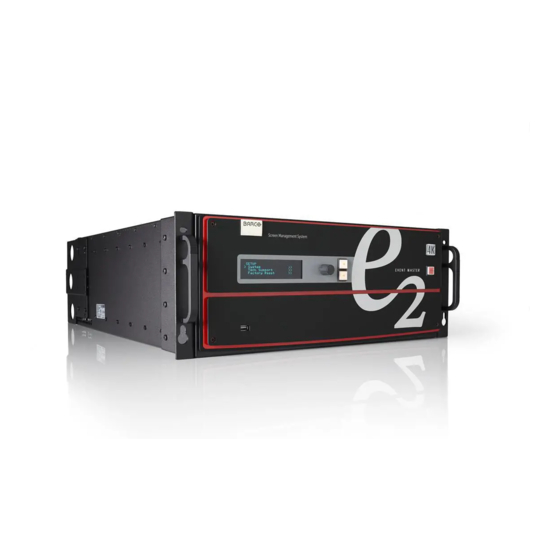
E2 Gen 2
Event Master
Screen Management System
Quick Start Guide
Download Product Manual
Product manuals and documentation are available online at www.barco.com/td/R9009203
Registration may be required; follow the instructions given on the website.
IMPORTANT!
Read Installation Instructions before connecting equipment to the mains power supply.
E2 Gen 2 Setup
Note: Refer to the Event Master Devices User's Guide (R5905948) for detailed
system specifications, descriptions, and operation instructions.
Any item contained in this document may change without notice.
7
1
6
1 Inputs
2 Multiviewers
3 PC with Event Master
control software
4 Ethernet switch
5 Outputs
8
2
MVR
MVR
9
3
4
6 USB port
7 Display
8 ADJUST knob
9 SEL and ESC buttons
10 Power switch
10
5
Advertisement
Table of Contents

Related Manuals for Barco E2 Gen 2


Summary of Contents for Barco E2 Gen 2
- Page 1 Screen Management System Quick Start Guide Download Product Manual Product manuals and documentation are available online at www.barco.com/td/R9009203 Registration may be required; follow the instructions given on the website. IMPORTANT! Read Installation Instructions before connecting equipment to the mains power supply.
- Page 2 System Setup Ensure that the unit is physically secured in a rack or is placed on a flat surface with stable support. If the unit is installed in a rack, it is mandatory that the rear brackets are also installed. Connect all sources, displays, and peripherals to the E2 according to your event’s requirements.
- Page 3 – Card configurations vary based on model; your configuration may be di erent. – E2 Gen 2 power supplies (red handle) are not backward compatible with E2 Gen 1 or S3 power supplies (black handle). Page 3 of 8...
- Page 4 Link Connections Check the cable orientation for keying. The cable fits in only one orientation. Fully insert the cable into the connector on the Link Card. If the cable resists full insertion, do not force it; pull the cable out, check its orientation, and reinsert it.
- Page 5 Event Master Control Software Flowchart C1: Discover C2: Connect C3: System Parameters (Native Rate, Genlock Mode, and Preset Conflict Mode) C6: Add Outputs C4: Add C5: Add C7: Add MVR Backgrounds Inputs Outputs (Turn on Test Patterns) C8: Add Screen Destinations C9: Add Aux Destinations...
- Page 6 Configuration Menu C8,9 Configuration Menu C1: Discovery – When the Event Master control software loads, it automatically discovers the devices connected to the network. These devices are listed on the left-hand side of the configuration screen. C2: Connect – Click on the device you want to connect and drag it in the middle area.
- Page 7 Programming Menu Programming Menu P1: Select thumbnails for Backgrounds – Press Refresh All, or select the thumbnails to represent the Backgrounds. P2: Select thumbnails for Inputs &Stills – Press Refresh All, or select the thumbnails to represent the Inputs and Stills. P3: Create Source Files –...
- Page 8 S1: Options – On the Options tab click on the boxes to select system wide user preferences such as Layer positioning. S2: Tools – Allows users to perform Backup and Restore operations or download the latest software from the Barco website. S3: Dashboard – Provides status information regarding the cards and other system diagnostic information.
Need help?
Do you have a question about the E2 Gen 2 and is the answer not in the manual?
Questions and answers