Table of Contents
Advertisement
Quick Links
Advertisement
Chapters
Table of Contents

Related Manuals for Barco ImagePRO-II Jr


Summary of Contents for Barco ImagePRO-II Jr
- Page 1 ImagePRO-II Jr User’s Guide Addendum • Manual #: 26-0904101-00 • Revision: 01...
-
Page 2: Table Of Contents
Table of Contents Introduction ............... 7 ImagePRO-II Jr Product Overview ......7 Hardware Orientation ..........8 3.1. Front Panel ................8 3.2. Rear Panel ................9 ImagePRO-II Family Comparison ......12 26-0904101-00 Rev 01.00... -
Page 3: Introduction
1. Introduction This addendum is only intended to introduce you to ImagePRO-II Jr and provide an overview of the ImagePRO-II Jr product. For detailed operating instructions, please refer to the ImagePRO-II User’s Guide that can be found on your Product CD. -
Page 4: Hardware Orientation
Following are descriptions of each front panel control feature: 1) USB Port The USB port is provided to support uploading and downloading system configurations and logos, and upgrading ImagePRO-II Jr firmware. 2) Display Section The Display Section consists of a four-line display screen. Refer to “The Display Section”... -
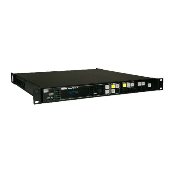
Page 5: 3.2. Rear Panel
Following are descriptions of each rear panel connector: 1) AC Connector One AC Connector with a power switch is provided to connect the ImagePRO-II Jr to your facility’s AC power source through the supplied power cord. The integral switch turns the unit on and off. (100-240 VAC, 50-60Hz) - Page 6 2) Ethernet Port One RJ-45 connector is provided for 10/100Base-T Ethernet Communications with the ImagePRO-II Jr. The port is used for running the Web Interface, for diagnostics, and for connection to an external device such as the Encore or ScreenPRO-II Controller.
- Page 7 Genlock signal to another device downstream of the ImagePRO- II Jr and will continue to function when the ImagePRO-II Jr is turned off. When the ImagePRO-II Jr is genlocked and the lock source is lost for some reason, the output of the unit will automatically switch to “free-run”...
-
Page 8: Imagepro-Ii Family Comparison
4. ImagePRO-II Family Comparison ImagePRO-II Dual ImagePRO-II Jr ImagePRO-II ImagePRO-II Audio ImagePRO-II Dual with Audio Analog Universal EDID Loop-through DVI with EDID Dual-Link HDCP Loop-through SDI 3G/HD/SD Dual-Link Loop-through HDMI with HDCP & EDID Display Port with HDCP & EDID... - Page 9 q~ÄäÉ=çÑ=`çåíÉåíë `Ü~éíÉê=N fåíêçÇìÅíáçå =K=K=K=K=K=K=K=K=K=K=K=K=K=K=K=K=K=K=K=K=K=K=K=K=K=K=K=K=K=K=K=K=K=K=K=K=K=K=K=K=K=K= N Chapter Structure ..........1 How to Use This Guide.
- Page 10 Table of Contents Installation Requirements ........20 Installing the ImagePRO-II.
- Page 11 Table of Contents About Genlock Settings ......68 Saving an Output Configuration ..... . 69 Restoring Output Configuration Default Values .
- Page 12 Table of Contents About the 3D/Dual Channel Option ....... 105 Switching System Modes.
- Page 13 Table of Contents Rotating Lists........140 Web App Interface Menu Tree .
- Page 14 Table of Contents ^ééÉåÇáñ=_= oÉãçíÉ=`çåíêçä=mêçíçÅçäK=K=K=K=K=K=K=K=K=K=K=K=K=K=K=K=K=K=K=K=K=K=K=K=K=K=K=K=KNUP In This Appendix ..........183 Introduction.
- Page 15 Table of Contents OTPM type rast diag ......203 PANH nnn.n ........203 PANHV hhh.h vvv.v.
-
Page 16: Chapter Structure
NK==fåíêçÇìÅíáçå This chapter is designed to introduce you to the ImagePRO-II and to the content of and conventions used in this guide. The following topics are included in this chapter: • Chapter Structure • How to Use This Guide • Conventions •... - Page 17 NK==fåíêçÇìÅíáçå How to Use This Guide eçï=íç=rëÉ=qÜáë=dìáÇÉ Following are important tips for streamlining your use of this User’s Guide in its electronic PDF form. k~îáÖ~íáåÖ Use Acrobat Reader’s bookmarks to navigate to the desired location. All chapter files have the same bookmark structure for instant navigation to any section. Please note: •...
- Page 18 NK==fåíêçÇìÅíáçå Terms and Definitions qÉêãë=~åÇ=aÉÑáåáíáçåë The following terms and definitions are used throughout this guide: • Area of Interest — The portion of the output display that a video image occupies. • Composite Video — A color video format that combines YUV signals into one channel, transmitting brightness/luma (Y) and colors/chroma (U and V) over one cable.
-
Page 19: Imagepro-Ii Universal Video Processor
For more information about the Web Interface, refer to Chapter 5, Web Remote Control Operations, on page 129. ™ You can also operate the ImagePRO-II remotely using the Barco Encore Controller ™ (release 2.32 or higher), or the ScreenPRO-II Controller. - Page 20 Programmable input and output Extended Display Identification Data (EDID) Remote control via a Web Interface or the Barco Encore (release 2.32 or higher) or ScreenPRO-II Controllers Front panel lockout for remote control applications •...
- Page 21 129 for more information about the Web Interface. • The ImagePRO-II also can be remotely controlled using the Barco Encore (release 2.32 or higher) or ScreenPRO-II Controller. For more information, refer to the Encore Presentation System User’s Guide or the ScreenPRO-II Controller User’s Guide.
-
Page 22: Imagepro-Ii Front Panel
OK==e~êÇï~êÉ=lêáÉåí~íáçå få=qÜáë=`Ü~éíÉê This chapter provides detailed information about the ImagePRO-II’s hardware. The following topics are discussed: • ImagePRO-II Front Panel • ImagePRO-II Rear Panel ImagePRO-II • User’s Guide... -
Page 23: The Display Section
2. Hardware Orientation ImagePRO-II Front Panel fã~ÖÉmolJff=cêçåí=m~åÉä The figure below illustrates the ImagePRO-II front panel. Figure 2-1. ImagePRO-II Front Panel Chassis Handles Menu Navigation Section LOGO and BLACK Buttons USB Port Menu Access Buttons FRZ Button Display Section Input Buttons Following are descriptions of each front panel control feature: Chassis Handles Two Chassis Handles are provided for ease of installation and transportation. -
Page 24: The Frz Button
2. Hardware Orientation ImagePRO-II Front Panel FRZ Button FRZ (FREEZE) enables you to freeze a displayed image. Refer to The FRZ Button on page 11 for more information. qÜÉ=aáëéä~ó=pÉÅíáçå The Display Section consists of a 4-line x 24-character screen that shows all ImagePRO-II menus, sub-menus, and messages. - Page 25 2. Hardware Orientation ImagePRO-II Front Panel jÉåì=^ÅÅÉëë=_ìííçåë TEST SETUP PAN/ AUDIO ZOOM Figure 2-4. Menu Access Buttons The Menu Access Buttons provide entry to specific locations in the menu system: • The SETUP button accesses the Setup Menu, the ImagePRO-II’s top-level menu.
- Page 26 2. Hardware Orientation ImagePRO-II Front Panel fåéìí=_ìííçåë Input buttons 1 through 5 correspond to the five standard input connectors on the rear panel. These buttons select the source signal that you want to display. DVI-I HD-15 HDMI SDI-1 SDI-2 Figure 2-5. ImagePRO-II Input Buttons The sixth button is reserved for use with the optional 3D/Dual Channel mezzanine.
-
Page 27: Imagepro-Ii Rear Panel
2. Hardware Orientation ImagePRO-II Rear Panel rëáåÖ=cêçåí=m~åÉä=_ìííçåë Pressing a front panel button once causes that button to light up. If the button is associated with a menu system, the display shows the top-level menu for that button. For example, pressing SEL at the Status Menu displays the Setup Menu. If the button performs a function, that function begins. - Page 28 2. Hardware Orientation ImagePRO-II Rear Panel Following are descriptions of each rear panel connector: AC Connector One AC Connector with a power switch is provided to connect the ImagePRO-II to your facility’s AC power source through the supplied power cord. The integral switch turns the unit on and off.
-
Page 29: Dual Channel Mezzanine
2. Hardware Orientation ImagePRO-II Rear Panel 14) DisplayPort Output 15) SDI-2 Output pPa=póåÅ=`çååÉÅíçêë Conforming to the VESA 3D specification, these miniDIN 3-pin connectors are used to indicate which eye corresponds to the current frame of single-stream 100/120 Hz video. The output is always active when the output S3D format is Sequential and the input must be connected whenever an S3D Sequential source is being processed through DVI or HDMI. -
Page 30: Safety Precautions
PK==e~êÇï~êÉ=fåëí~ää~íáçå få=qÜáë=`Ü~éíÉê This chapter provides comprehensive installation instructions for the ImagePRO-II system’s hardware. The following topics are discussed: • Safety Precautions • Unpacking and Inspection • Site Preparation • Rack-Mount Installation • Cable and Adapter Information • Installation ImagePRO-II • User’s Guide... - Page 31 3. Hardware Installation Safety Precautions p~ÑÉíó=mêÉÅ~ìíáçåë= For all ImagePRO-II installation procedures, please observe the following important safety and handling rules to avoid damage to yourself and the equipment: • To protect users from electric shock, ensure that the chassis connects to earth via the ground wire provided in the AC power cord.
- Page 32 3. Hardware Installation Cable and Adapter Information • Rack mount each ImagePRO-II chassis from the front rack ears using four rack screws (not supplied). Rack threads may be metric or otherwise — depending upon the rack type. • Install the lower of the two mounting holes first. `~ÄäÉ=~åÇ=^Ç~éíÉê=fåÑçêã~íáçå...
- Page 33 3. Hardware Installation Cable and Adapter Information Avertissement La choix de la ligne de voltage se réalise automatiquement par le ImagePRO-II Transformateur Graphique. On n'a pas besoin du controller usager pour la choix de la ligne de voltage. Warnung Das ImagePRO-II gerät mu beim Anschlu an 240V ~ mit einer vom VDE auf 250V/ 10A geprüften Netzleitung mit einem Schukostecker ausgestattet sein.
- Page 34 3. Hardware Installation Installation fåëí~ää~íáçå With five input sources and six output connectors, there are many possible ways to configure an ImagePRO-II installation. The following figure illustrates one possible installation for the ImagePRO-II. Output 1 DVI-D Input 1 DVI-I / Universal Analog Input 2 HD-15 Output 2...
- Page 35 3. Hardware Installation Installation Chapter 4, or by using zoom and pan settings, as described in Creating a View on page 78 in Chapter 4. fåëí~ää~íáçå=oÉèìáêÉãÉåíë To set up the ImagePRO-II, you will need the following equipment: Table 3-2. Equipment List, Basic ImagePRO-II System Qty.
- Page 36 3. Hardware Installation Installation Connect the video source(s) to the analog or digital input connectors as required. Output Connections To connect the ImagePRO-II to a digital projector or other digital display, connect one of the following output connectors to the appropriate input of the display device: •...
- Page 37 3. Hardware Installation Installation Connect the ImagePRO-II’s Ethernet port to the external device. The devices you can use to control the ImagePRO-II remotely include: ® • Smartphone (iPhone , Android™, etc.) • PC, notebook, laptop, or tablet with a compatible OS and browser There may be additional steps needed, such as turning on the DHCP feature or setting a static IP address.
- Page 38 QK==jÉåì=lêáÉåí~íáçå få=qÜáë=`Ü~éíÉê This chapter describes all ImagePRO-II system menus, including how they are accessed and the functions or parameters that are available. The principal menu trees are presented in block diagram format throughout the chapter. The following topics are included in this chapter: •...
- Page 39 Program Loading Please Wait Figure 4-1. System Initialization Message 1 ImagePRO-II Barco Inc Version 1.00 Initializing… Figure 4-2. System Initialization Message 2 The version number in the preceding menu shows the software version that is installed.
- Page 40 4. Menu Orientation Quick Setup and Operation nìáÅâ=pÉíìé=~åÇ=léÉê~íáçå To quickly set up and begin operating your system, follow the steps in this section. Links are provided to the appropriate sections in this guide, if you require more information. Connect power — Ensure that power is properly connected to the ImagePRO-II. (Chapter 3, Installation, page 19.) Connect inputs —...
- Page 41 4. Menu Orientation Quick Setup and Operation 15. Save system configuration — After completing all system adjustments, save the system configuration. (This chapter, Saving System State, page 96.) 16. Ready to roll — With all output, input and system configurations saved, press the desired input button.
- Page 42 “Channel,” or “Ch” are available only when the optional dual- channel/S3D mezzanine is installed. The Audio Menu is available only when the optional Audio mezzanine is installed. For information about these options, contact your Barco sales representative or refer to Appendix D “Contact Information”...
- Page 43 4. Menu Orientation ImagePRO-II Menu Tree Status Menu Setup Menu Output In Auto Acq Custom Formats Views Transition System Logo Input Recall Capture Logo Input Format Output Format Format Name Trans With Black Invalid Type Out Auto Config Save Trans Time HDCP Delete Logo Save As...
- Page 44 4. Menu Orientation Using the Menu System rëáåÖ=íÜÉ=jÉåì=póëíÉã This section describes the conventions for using the ImagePRO-II’s menu system. For reference, the following illustration shows the Setup Menu. SETUP > Input >> Output >> In Auto Acquire Custom Formats >> Views >>...
- Page 45 4. Menu Orientation Using the Menu System j~âáåÖ=~=jÉåì=pÉäÉÅíáçå To select a menu item, use the ADJUST knob to scroll to the item, then press the SEL button on the front panel: • To scroll through a menu: Turn the ADJUST knob counter-clockwise to scroll down. Turn the ADJUST knob clockwise to scroll up.
- Page 46 4. Menu Orientation Quick Function Reference nìáÅâ=cìåÅíáçå=oÉÑÉêÉåÅÉ Use the following table to quickly access information by clicking the hyperlinks to section names or page numbers. Table 4-1. ImagePRO-II Quick Function Reference Table To Learn About Refer to Section Page 3D settings Operating the ImagePRO-II in 3D page 114 Mode...
- Page 47 4. Menu Orientation About the Status Menu ^Äçìí=íÜÉ=pí~íìë=jÉåì The Status Menu is the ImagePRO-II’s top-level menu, which appears by default at system startup. This menu provides input, Genlock, and output information. The following figure illustrates a sample Status Menu if you use the standard ImagePRO-II. 1280x1024p @59.94 Genlock: N/A CHA:...
- Page 48 4. Menu Orientation About the Status Menu • The second line indicates: The Genlock status for the output channel. The options are: • Lock to external source • Lock to input number... • Freerun (default) The type of input signal being processed. Options are CVBS, YC, SDI, RGB, YPbPr, DVI-I, HDMI and DP.
- Page 49 4. Menu Orientation About the Setup Menu ^Äçìí=íÜÉ=pÉíìé=jÉåì The Setup Menu, shown in the following illustration, is the menu from which you access all operational menus. To display the Setup Menu, press the SETUP button on the front SETUP panel. SETUP >...
- Page 50 4. Menu Orientation Configuring Inputs `çåÑáÖìêáåÖ=fåéìíë The Input Menu is used to adjust all parameters relating to inputs. Using this menu, you can set all of the configuration options for the selected input. This section provides detailed information about setting up and using inputs. To quickly position and size video on an LED wall or monitor, refer to Setting up an LED Wall page 101 of this chapter.
- Page 51 4. Menu Orientation Configuring Inputs fåéìí=jÉåì=cìåÅíáçåë=~åÇ=pìÄãÉåìë The following Input Menu functions and submenus are covered in this section: Setting the Input Format Resetting Masking Effects Selecting the Input Type Adjusting Timing Parameters Selecting the Colorspace Adjusting Edge Timings Using 1:1 Sample Setting Input Contrast and Brightness Setting the Aspect Ratio Setting Input Color Balance...
- Page 52 4. Menu Orientation Configuring Inputs As you change the input Type, the default Colorspace setting changes, too. For example, if you select YP or YC, the Colorspace changes to SMPTE. If you select RGB, the Colorspace changes to RGB. For details about these options, refer to Selecting the Colorspace on this page.
- Page 53 4. Menu Orientation Configuring Inputs pÉííáåÖ=íÜÉ=^ëéÉÅí=o~íáç The Input Aspect Ratio Submenu, shown in the following illustration, provides one way to affect aspect ratio. The ImagePRO-II selects and displays the input video aspect ratio according to the selected input format. INPUT ASPECT RATIO Set Mode Ratio Figure 4-3.
- Page 54 4. Menu Orientation Configuring Inputs S IZ IN G A D JU S T > H S ize 1024 V S ize H P os V P os R eset S ize M ask To p 0.00% M ask B otto m 0.00% M ask Left 0.00%...
- Page 55 4. Menu Orientation Configuring Inputs Original image size Image resized horizontally Figure 4-7. Horizontal Resizing • V Size is also center-based. Decreasing V Size “stretches” the image across the active area, along the vertical plane. This setting adjusts both the top and bottom edges simultaneously, while the center point of the image remains stable.
- Page 56 4. Menu Orientation Configuring Inputs • Select H Pos to pan left or right across the image, to the portion you want to display. Values are in pixels. The H Pos value of 0 represents the horizontal center of the active area. •...
- Page 57 4. Menu Orientation Configuring Inputs Press SEL to confirm your choice. Note To restore the original unmasked image, refer to Resetting Masking Effects on page 43. rëáåÖ=j~ëâ=mêÉëÉíë The Mask Presets feature on the input Sizing Adjust Submenu provides a convenient way to mask all the edges of an image at once, to a preset aspect ratio.
- Page 58 4. Menu Orientation Configuring Inputs Figure 4-11. 16:9 Image (top) with 5:4 Masking Preset (bottom) The image on display is the base image to which the mask is applied. If an image has already been masked to a 5:4 aspect ratio, and you mask it again using the 1:1 preset, the system creates the 1:1 mask using the previous 5:4 image as a base.
- Page 59 4. Menu Orientation Configuring Inputs ^ÇàìëíáåÖ=qáãáåÖ=m~ê~ãÉíÉêë The ImagePRO-II supports adjusting the positioning of the input signal’s active area. There are two timing adjustment menus: 1:1 Timing Adjust and Edge Timing Adjust. The 1:1 Timing Adjust Submenu displays the timing information of the input signal, shown in the following illustration.
- Page 60 4. Menu Orientation Configuring Inputs EDGE TIMING ADJUST > Right Edge 2460 Left Edge Top Edge Bottom Edge Figure 4-14. Edge Timing Adjust Submenu (sample) Using this menu, you can set the exact locations of the active video edges, when 1:1 Sample is Off.
- Page 61 4. Menu Orientation Configuring Inputs • As with the global Contrast and Brightness menus, you can adjust both contrast and brightness within a range of 25% to 150%. The default setting for both contrast and brightness is 100%. • Hue is measured in degrees. The range is -90 to +90 degrees. The default setting is 0.
- Page 62 4. Menu Orientation Configuring Inputs resolution is reduced in this mode, video processing delay is also significantly reduced. The following table shows the maximum delay for each mode, for both interlaced and progressive video. Table 4-3. Maximum Video Processing Delay Video Processing Delay DeInterlace Mode (Maximum)
- Page 63 4. Menu Orientation Configuring Inputs ^Äçìí=fåéìí=`çåÑáÖìê~íáçåë The ImagePRO-II supports saving up to 64 input configuration files in non-volatile memory, each of which is available to the five six physical inputs. Input configuration files contain settings that can govern everything from pixel resolution to aspect ratio and color balance —...
- Page 64 4. Menu Orientation Configuring Inputs Use the ADJUST knob to scroll to the first character you want to use for the format name. Note Turning the ADJUST knob clockwise once moves to the next letter of the alphabet. If you start with an upper-case letter, as shown in the preceding illustration, then the next letter is also a capital letter.
- Page 65 4. Menu Orientation Configuring Inputs If you have used all 64 input configurations, the following message appears. SAVE CONFIG AS LIBRARY FULL <ESC> = Continue Figure 4-20. Library Full Message When you see this message, press ESC and go to the Delete Config Submenu to delete a different configuration file.
- Page 66 4. Menu Orientation Configuring Inputs Use the ADJUST knob to scroll through the list to the file you wish to recall. Note The Recall Config Submenu displays only configurations that match the current input format and type. Press SEL to select the file. Scroll down to Recall Config and press SEL again.
- Page 67 4. Menu Orientation Configuring Outputs `çåÑáÖìêáåÖ=lìíéìíë= The Output Menu enables you to configure the ImagePRO-II’s outputs and save your settings if you wish. This section provides detailed information about setting up and using outputs. To quickly position and size video on an LED wall or monitor, refer to Setting up an LED Wall on page 101 of this chapter.
- Page 68 4. Menu Orientation Configuring Outputs Output Output Format Out Auto Config Select Output Auto Config Status Area of Interest H Size V Size H Pos V Pos Reset Timing Adjust H Total H Position H Active H Sync V Total V Position V Active V Sync...
-
Page 69: About Genlock Settings
4. Menu Orientation Configuring Outputs lìíéìí=jÉåì=cìåÅíáçåë=~åÇ=pìÄãÉåìë All Output Menu functions and submenus are discussed in the following sections: Setting the Output Format Setting the SDI Type Using Output Auto Config Setting ColorSpace, Sample Rate, and Bit Depth Viewing Output EDID Information Setting Output Effects Setting the Area of Interest About Genlock Settings... - Page 70 4. Menu Orientation Configuring Outputs For devices connected to the ImagePRO-II, you can read the name of the digital display and the preferred video format that the display uses. The Output Auto Config Submenu supports letting the output device on the DVI-D, HD-15, HDMI, or DisplayPort connector change the output format and the audio sample rate...
- Page 71 4. Menu Orientation Configuring Outputs For the output connector you selected, the Status field indicates whether the connector has read the EDID information correctly. Possible status information includes: n/a — The EDID information is not available, possibly because no output device is connected.
- Page 72 4. Menu Orientation Configuring Outputs Figure 4-28. Adjusted Area of Interest To adjust the Area of Interest, you use four settings on the Area of Interest Submenu, shown in the following illustration. You can also restore the default AOI. AREA OF INTEREST >...
- Page 73 4. Menu Orientation Configuring Outputs Figure 4-31. V Size Adjustment • H Pos — Using H Pos, you can move the image horizontally. The default value is 0, representing the left edge of the active area. Increasing the H Pos value moves the image to the right.
- Page 74 4. Menu Orientation Configuring Outputs If you have the 3D/Dual Channel mezzanine installed, and the System Mode is set to Dual2K, select a channel to work with, or accept the default setting of All. To change the horizontal size of the AOI, select H Size and turn the ADJUST knob counter-clockwise.
- Page 75 4. Menu Orientation Configuring Outputs ^ÇàìëíáåÖ=lìíéìí=qáãáåÖ From the Output Menu, select Timing Adjust to display the Output Timing Adjust Submenu. On this submenu, shown in the following illustration, you can change the selected output’s total, active and sync settings, and reposition video on the output. Note All but the most advanced users are advised to avoid changing the output timing values.
- Page 76 4. Menu Orientation Configuring Outputs • V Position — Adjusts (in lines) the offset of the start of the output active area from V sync. • V Active — Adjusts (in lines) the vertical size of the output active area. •...
- Page 77 4. Menu Orientation Configuring Outputs • For HD-15 Sync, the available options are: CVBS / YC / SOG/Y / CSync +H +V +H -V -H+V -H-V The default setting for HD-15 Sync is SOG/Y for most formats. For NTSC and PAL, the default setting is CSync with equalizations on.
- Page 78 4. Menu Orientation Configuring Outputs pÉííáåÖ=`çäçêpé~ÅÉI=p~ãéäÉ=o~íÉI=~åÇ=_áí=aÉéíÜ= The ImagePRO-II supports setting the output colorspace, sample rate and bit depth. Within limits, you can modify these settings for some outputs. From the Output Menu, select the ColorSpace/Bit Depth option. The following menu appears, showing valid options for each output type.
- Page 79 4. Menu Orientation Configuring Outputs RGB, 4:4:4, 24 bit RGB, 4:4:4, 30 bit RGB, 4:4:4, 36 bit YCbCr, 4:4:4, 24 bit YCbCr, 4:4:4, 30 bit YCbCr, 4:4:4, 36 bit The default setting upon format change is: RGB, 4:4:4, to the maximum bit depth supported, as given in the EDID information The default setting if EDID information is invalid or not present is: RGB, 4:4:4, 24 bit...
- Page 80 4. Menu Orientation Configuring Outputs OUT EFFECTS > Channel Contrast Figure 4-40. Output Effects Submenu in Dual-Channel Mode In either mode, the options on this menu are: • Contrast — For outputs, the Contrast adjustment range is 0% to 200%. The default setting is 100%.
- Page 81 4. Menu Orientation Configuring Outputs Figure 4-42. Full-Color Image and Monochrome Effect • Invert — This option inverts the output image’s color hues by 180 degrees. For example, on the color wheel, red and cyan hues are 180 degrees apart. 180 degrees Figure 4-43.
- Page 82 4. Menu Orientation Configuring Outputs Figure 4-44. Full-Color Image and Inverted Effect If you invert a monochrome image, white becomes black, black becomes white, dark gray becomes light gray, and light gray becomes dark gray. Figure 4-45. Monochrome Image and Inverted Effect •...
- Page 83 4. Menu Orientation Configuring Outputs Figure 4-46. Image Flip — Vertical The options are H, V, H+V, and Off. The default setting is Off. • Strobe Mode — This option turns the strobe effect or Off. The default setting is Off. If Strobe Mode is on, the timing of the strobe’s flash effect is determined by the Strobe Rate setting.
- Page 84 4. Menu Orientation Configuring Outputs Channel — If you have the 3D/Dual Channel option installed, you can select the channel to which these offsets will apply. If you are using the standard ImagePRO-II, this option is not available. H Offset — Sets the horizontal offsets, in increments of +/- one-half line, in pixels.
-
Page 85: Working With Test Patterns
4. Menu Orientation Working with Test Patterns oÉëíçêáåÖ=lìíéìí=`çåÑáÖìê~íáçå=aÉÑ~ìäí=s~äìÉë To remove user-defined configuration settings and restore the default values for the current output, select Reset Config from the Output Menu. If you select this command, custom configurations are not restored the next time you power up the ImagePRO-II. With the 3D/Dual Channel mezzanine installed and the system mode set to Dual2K, the Out Reset Config Submenu appears. - Page 86 4. Menu Orientation Working with Test Patterns pÉííáåÖ=ré=~=qÉëí=m~ííÉêå=áå=pí~åÇ~êÇ=póëíÉã=jçÇÉ To set up a test pattern on an output in Standard system mode, use the following procedure: Press the TEST PAT button. TheTest Pattern Menu appears, as shown in TEST Figure 4-50 on page 70. In standard system mode, the first three options on this menu support setting up the test pattern in the default active area and creating an optional raster box around it.
-
Page 87: Acquiring An Input Signal
4. Menu Orientation Acquiring an Input Signal If you selected A or B, and you want to set up a test pattern on the second channel, scroll back up to Channel and select the channel. Change any of the settings you wish to change. Press ESC to return to the Status Menu. -
Page 88: Creating Custom Formats
4. Menu Orientation Creating Custom Formats `êÉ~íáåÖ=`ìëíçã=cçêã~íë To access the Custom Formats Menu, select Custom Formats from the Setup Menu. Using the Custom Formats Menu, you can create custom video formats from existing formats. When you save a custom or edited format, the ImagePRO-II stores it in a library. During auto-acquisition (i.e., when In Auto Acquire is On), the system searches this library before it searches the standard system library. - Page 89 4. Menu Orientation Creating Custom Formats CUSTOM FORMATS > NTSC (480i) Save As >> Delete >> H Total H Active H Front Porch H Sync H Rate (KHz) 31.25 V Total V Active V Front Porch V Sync V Rate (Hz) 59.94 Interlaced Figure 4-53.
- Page 90 4. Menu Orientation Creating Custom Formats The Interlaced option is either or Off. When Interlaced is On, the V Total value is forced to an odd number. When you press SEL to select an option in this list, the navigation cursor changes to an edit cursor.
- Page 91 4. Menu Orientation Creating Custom Formats SAVE FORMAT AS > MyFormat Save -- Format Saved -- Figure 4-55. Format Saved Message If the format library is full, the following message appears. Press ESC, then decide if you want to delete one of the existing formats to make room in the library. SAVE CONFIG AS LIBRARY FULL <ESC>...
- Page 92 4. Menu Orientation Creating Custom Formats aÉäÉíáåÖ=~=`ìëíçã=cçêã~í You can delete any custom format from your format library. You cannot delete a system format. Note Be sure the format is not in use before you attempt to delete it. You cannot delete a format if it is: •...
-
Page 93: Creating And Saving Views
4. Menu Orientation Creating and Saving Views `êÉ~íáåÖ=~åÇ=p~îáåÖ=sáÉïë A view is a combination of the pan and zoom settings on an input. The Views Menu lets you name and store up to 16 custom views, along with the Default view. The Default view displays the image at 100% zoom and 0% pan, filling the screen. -
Page 94: Saving A View To An Input
4. Menu Orientation Creating and Saving Views • Units defines the units you are using. The options are Pixel and Percent. • Fill H/V adjusts the image to fill the display both horizontally and vertically. • Save View saves the current input’s view settings. For more information, refer to Saving a View to an Input on page 79. - Page 95 4. Menu Orientation Creating and Saving Views p~îáåÖ=~=sáÉï=íç=íÜÉ=póëíÉã= If you want to save a view you created and make it available to other inputs, you can save it to the system, using the View Menu. After you create pan and zoom settings for a view, use the following procedure to name the view and save it.
- Page 96 4. Menu Orientation Creating and Saving Views oÉÅ~ääáåÖ=~=póëíÉã=sáÉï The Recall View Submenu lets you apply a saved system view to the selected input. You can recall any previously saved system view. Note Recalling applies the selected view to the input, but does not save the view to the input.
-
Page 97: About Transition Effects
4. Menu Orientation About Transition Effects A confirmation message appears. The custom settings assigned to the view are deleted, and the view is restored to its default values. The preset name of the view remains in the system. ^Äçìí=qê~åëáíáçå=bÑÑÉÅíë The ImagePRO-II supports three transition effects that occur when you switch between inputs: •... - Page 98 4. Menu Orientation About Transition Effects TRANSITION > Trans With Blk Fade Trans Time Figure 4-70. Transition Menu pÉííáåÖ=qê~åëáíáçåë To set the transition type and timing, use the following procedure: Select the input you want to transition from. From the Setup Menu, select Transition. The Transition Menu appears. Set the transition mode by selecting Trans With, and scrolling to the type you want.
-
Page 99: Using The System Menu
4. Menu Orientation Using the System Menu rëáåÖ=íÜÉ=póëíÉã=jÉåì The System Menu enables you to configure certain system-wide settings for the ImagePRO-II. To access the menu, select System from the Setup Menu. The following topics are discussed in this section: • The System Menu Tree •... -
Page 100: Setting Black Invalid
4. Menu Orientation Using the System Menu póëíÉã=jÉåì=cìåÅíáçåë=~åÇ=pìÄãÉåìë System Menu functions allow you to view and change settings such as HDCP status, input EDID information, and Ethernet options, and save your changes. You can also save configurations and formats to a flash drive, and restore them from the drive later. This section includes the following topics: •... - Page 101 4. Menu Orientation Using the System Menu Please note the following important points: • You can turn the HDCP option on or off. If the option is turned off and the signal is encrypted, the ImagePRO-II does not send the signal to the output device. •...
- Page 102 4. Menu Orientation Using the System Menu IN HDCP STATUS > In 1 (DVI-I) In 3 (HDMI) In 4 (DP) Figure 4-73. Input HDCP Status Menu When you first power up the ImagePRO-II, this menu displays the default values for each of the three inputs, as shown in the preceding illustration.
- Page 103 4. Menu Orientation Using the System Menu • MinDelay. In this mode, the output format is automatically mapped to the input format and locked for minimal delay. This mode is useful when you want to convert a 3G Level B input to a 3G Level A output or vice versa. •...
- Page 104 4. Menu Orientation Using the System Menu U S B B A C K U P C O N FIG > S ysB ackup1 B ackup C onfig (FA T filesystem only) Figure 4-76. USB Backup Config Submenu If you wish to change the default name of the backup configuration, press SEL. Use the ADJUST knob to change the name, as described in Saving an Input Configuration...
- Page 105 4. Menu Orientation Using the System Menu A message confirms the restore operation and instructs you to reboot the ImagePRO-II. Note You must reboot the ImagePRO-II to use the restored configuration file. _~ÅâáåÖ=ré=içÖç=cáäÉë After you capture and save a logo image, you can back it up to a flash drive. With the 3D/ Dual Channel mezzanine installed and the system mode set to Dual2K, you can back up the image on either channel.
- Page 106 Set a static IP address for the ImagePRO-II, along with a subnet mask and gateway. This feature is available only if DHCP is turned Off. • Set up the ImagePRO-II connection to a Barco Encore or ScreenPRO-II Controller. • View the ImagePRO-II’s IP address.
- Page 107 4. Menu Orientation Using the System Menu When DHCP is off, you can manually enter a static IP address, along with a subnet mask and gateway, in the Set Static IP Submenu. Consult your network administrator for a valid IP address, subnet mask and gateway. pÉííáåÖ=~=pí~íáÅ=fm=^ÇÇêÉëë...
- Page 108 COM port communication. Verify with the network administrator that the ImagePRO-II can communicate with the computer. pÉííáåÖ=ré=Ñçê=íÜÉ=båÅçêÉ=çê=pÅêÉÉåmolJff=`çåíêçääÉê The Barco Remote Control Submenu sets up the ImagePRO-II for remote control through a Barco Encore or ScreenPRO-II Controller. BARCO REMOTE CONTROL > Unit ID 192.168.000.001...
- Page 109 4. Menu Orientation Using the System Menu Attempting remote connection Please wait ..Figure 4-84. Remote Connection Message When the connection is established, a confirmation message appears. `Ü~åÖáåÖ=fåéìí=bafa The ImagePRO-II’s EDID information is stored in non-volatile memory. This file contains the preferred and allowed resolutions for each EDID-capable input in the ImagePRO-II.
- Page 110 4. Menu Orientation Using the System Menu source device reads this information. The selections are 2 and 8. The default setting is 8. This feature is useful when the audio being played from the source is more than two channels, and you want to use the two analog audio outputs on the Audio mezzanine.
-
Page 111: Using A Logo Or Internal Black
4. Menu Orientation Using a Logo or Internal Black Front Panel Locked Out. Unit ID 18 Figure 4-88. Front Panel Locked Message To disable the front panel lock, press and hold the SEL and ESC buttons simultaneously for 3 seconds. When the panel is unlocked, the display screen displays the Status Menu. - Page 112 4. Menu Orientation Using a Logo or Internal Black This section discusses both methods of capturing, deleting, and restoring a logo or internal black. In addition to these methods, you can also downloading or restore a logo from a USB flash drive or from the ImagePRO-II Web Interface.
- Page 113 4. Menu Orientation Using a Logo or Internal Black the LOGO button. You can also determine whether a logo is stored in the system, and delete or erase the logo, using this menu. LOGO > Capture Logo Delete Logo Erase Logo Backup Logo >>...
-
Page 114: Deleting A Logo
4. Menu Orientation Using a Logo or Internal Black output, using the timings you create in Setting Transitions on page 83. When the logo is displayed: • The PAN/ZOOM button and the Input Menu are not available. • The Status Menu indicates LOGO as the input format and shows the resolution of the captured logo. -
Page 115: Erasing A Logo
4. Menu Orientation Using a Logo or Internal Black system memory. Note When data security is an issue, it is advisable to erase the logo rather than delete it. For information, refer to Erasing a Logo on page 100. To make a logo unavailable for use, use the following procedure: Select Logo from the Setup Menu. -
Page 116: Setting Up An Led Wall
4. Menu Orientation Setting up an LED Wall pÉííáåÖ=ìé=~å=iba=t~ää The LED Setup Submenu, shown in the following illustration, provides a quick way to position the video image on an LED wall or another display device. Select Setup > LED Setup to view this menu. LED SETUP >... - Page 117 4. Menu Orientation Setting up an LED Wall ZOOM/PAN > Channel Zoom H 1280 Zoom V Figure 4-94. Zoom/Pan Menu in Dual-Channel Mode This Zoom/Pan Menu provides the following options: Channel (available In dual-channel mode only), supports selecting a channel on which to adjust the video. Match Input 1:1 fills the Area of Interest with the unscaled input image.
-
Page 118: Using The Tech Support Menu
4. Menu Orientation Using the Tech Support Menu rëáåÖ=íÜÉ=qÉÅÜ=pìééçêí=jÉåì The Tech Support Menu, shown in the following illustration, provides quick access to Customer Support contact information, and also shows you the software version for your ImagePRO-II. TECH SUPPORT Version 2.00 Phone 866-374-7878 w w w . -
Page 119: Restoring Factory Default Settings
4. Menu Orientation Restoring Factory Default Settings oÉëíçêáåÖ=^ää=c~Åíçêó=pÉííáåÖë To restore all default settings to the ImagePRO-II, use the following procedure: Select Factory Reset from the Setup Menu. The Factory Reset Menu appears. Select Factory Reset. A prompt appears, asking if you want to clear all configurations, formats, and views. - Page 120 4. Menu Orientation About the 3D/Dual Channel Option ^Äçìí=íÜÉ=PaLaì~ä=`Ü~ååÉä=léíáçå The ImagePRO-II’s 3D/Dual Channel option is a user-installable mezzanine that offers two distinct but related capabilities: • Dual-channel capability, to display a single video source on separate output devices at different output resolutions •...
- Page 121 4. Menu Orientation Operating the ImagePRO-II in Dual-Channel Mode Warning! Chnl B logo & settings will be lost! <SEL> = Continue <ESC> = Cancel Figure 4-96. Warning Message for System Mode Switching This message indicates that you are switching from dual-channel mode to standard mode. If you press SEL, the video on Channel A is retained as the standard-mode output.
- Page 122 4. Menu Orientation Operating the ImagePRO-II in Dual-Channel Mode 1024x768 @59.94 Genlock: N/A CHA: 1280x720p @60 CHB: 1280x720p @60 Figure 4-97. Status Menu in Dual-Channel Mode Other menus — such as the Output Timing Adjust, Area of Interest, Input Sizing Adjust, and Zoom/Pan menus —...
- Page 123 4. Menu Orientation Operating the ImagePRO-II in Dual-Channel Mode O U T C O N N E C T O R M A P > O u t 1 ( D V I - D ) O u t 2 ( H D 1 5 ) O u t 3 ( H D M I ) O u t 4 ( D P ) O u t 5 ( S D I 1 )
- Page 124 4. Menu Orientation Operating the ImagePRO-II in Dual-Channel Mode Save Output Cfg? > <SEL> = Yes <ESC> = No Figure 4-100. Save Output Config Prompt Press SEL at this prompt if you want to save the output format to non-volatile memory.
- Page 125 4. Menu Orientation Operating the ImagePRO-II in Dual-Channel Mode OUT EFFECTS > Channel Contrast Figure 4-103. Output Effects Submenu in Dual-Channel Mode pÉííáåÖ=íÜÉ=^êÉ~=çÑ=fåíÉêÉëí=áå=aì~äJ`Ü~ååÉä=jçÇÉ With the 3D/Dual Channel mezzanine installed and the system mode set to Dual2K, the Area of Interest Menu includes a Channel field that lets you set the AOI separately for each channel.
- Page 126 4. Menu Orientation Operating the ImagePRO-II in Dual-Channel Mode ZOOM/PAN > Channel Zoom H 1280 Zoom V Figure 4-105. Zoom/Pan Menu — Dual-Channel Mode (sample) `êÉ~íáåÖ=~=sáÉï=áå=aì~äJ`Ü~ååÉä=jçÇÉ To create a view for a channel in dual-channel mode, use the following procedure: Press the PAN/ZOOM button.
- Page 127 4. Menu Orientation Operating the ImagePRO-II in Dual-Channel Mode USB BACKUP LOGO > Channel LogoBackupCHA_1 Backup Logo Figure 4-107. USB Backup Logo Submenu in Dual-Channel Mode Either accept the default channel or change this selection and press SEL. Scroll to the next line, which displays the default name for this logo. If you wish to change the name, press SEL.
- Page 128 4. Menu Orientation Operating the ImagePRO-II in Dual-Channel Mode dÉåäçÅâ=pÉííáåÖë=áå=aì~äJ`Ü~ååÉä=jçÇÉ Using the Output > Genlock Submenu in dual-channel mode, you can lock Channel B to Channel A, so that the sources remain in sync, or you can set Channel B to Freerun to remove this lock.
- Page 129 4. Menu Orientation Operating the ImagePRO-II in 3D Mode léÉê~íáåÖ=íÜÉ=fã~ÖÉmolJff=áå=Pa=jçÇÉ With the 3D/Dual Channel option installed, the ImagePRO-II can process both single- stream and dual-stream 3D video. Single-stream 3D is delivered on a single wire. Dual- stream video consists of two video signals, one containing the right-eye image and the other containing the left-eye image.
- Page 130 4. Menu Orientation Operating the ImagePRO-II in 3D Mode Table 4-4. Supported Input/Output Resolutions — Single-Stream 3D Video Signal Format Resolutions Top/Bottom 1920x1080p @23.98 Hz 1920x1080p @24 Hz 1280x720p @50 Hz 1280x720p @59.94 Hz 1280x720p @60 Hz Sequential Sequential progressive frames up to 2048x1200 @120 Hz (24 bits) on the DVI dual- link and DisplayPort connectors pÉííáåÖ=ré=fåéìíë=íç=aáëéä~ó=páåÖäÉJpíêÉ~ã=Pa=sáÇÉç...
- Page 131 4. Menu Orientation Operating the ImagePRO-II in 3D Mode L/R. Processes the video as if the left image is the right, and the right image is on the left. R/L. Processes the video as if the right image is on the left, and the left image is on the right.
- Page 132 4. Menu Orientation Operating the ImagePRO-II in 3D Mode Left/Right. The complete left and right images are displayed on different output connectors. You can use this option with the following pairs of connectors: • The DVI and HDMI connectors, with the DVI as the left image by default, and the HDMI as the right image by default.
- Page 133 4. Menu Orientation Operating the ImagePRO-II in 3D Mode iÉÑíLoáÖÜí=fã~ÖÉ=pï~ééáåÖ The miniDIN-3 connectors on the ImagePRO-II rear panel determine which eye corresponds to the current frame of single-stream 3D video. By default, on both inputs and outputs: • The DVI connector takes the left eye and HDMI takes the right eye. •...
- Page 134 4. Menu Orientation Operating the ImagePRO-II in Quad to Dual Mode léÉê~íáåÖ=íÜÉ=fã~ÖÉmolJff=áå=nì~Ç=íç=aì~ä=jçÇÉ Quad to Dual system mode supports driving a 4K projector. In Quad to Dual mode, two ImagePRO-II units accept single-link video signals from two pairs of input devices. The inputs can be paired on the SDI 1/SDI 2 connectors or the DVI/HDMI connectors.
- Page 135 4. Menu Orientation Working with Audio tçêâáåÖ=ïáíÜ=^ìÇáç When you install the optional Audio mezzanine, the ImagePRO-II can process both digital and analog audio. With this option, you can: • Process a video signal that contains embedded audio, on any output that supports audio •...
-
Page 136: Configuring Outputs With The Web App Interface
5. Web Remote Control Operations Configuring Outputs with the Web App Interface Figure 5-25. Area of Interest Page To change the Area of Interest, use any of the following settings: • H Size — Determines the width (in pixels) of the Area of Interest. This setting must be equal to or less than the H Active setting of the output timing. - Page 137 5. Web Remote Control Operations Configuring Outputs with the Web App Interface Figure 5-26. Output Auto Config Page To let the output device change the output format of the ImagePRO-II, use the following procedure: On the Output Auto Config page, select the field for one of the outputs. Click Auto Config.
-
Page 138: Setting Up Test Patterns With The Web App Interface
5. Web Remote Control Operations Setting Up Test Patterns with the Web App Interface pÉííáåÖ=ré=qÉëí=m~ííÉêåë=ïáíÜ=íÜÉ=tÉÄ=^éé=fåíÉêÑ~ÅÉ From the Web App Interface, you can set up test patterns on an output display, turn the Area of Interest raster box on or off, and set up diagonal motion for the pattern. To access the Test Patterns page from the Home page, select Test Patterns from the side menu. -
Page 139: Creating Pan And Zoom Settings With The Web App Interface
5. Web Remote Control Operations Creating Pan and Zoom Settings with the Web App Interface `êÉ~íáåÖ=m~å=~åÇ=wççã=pÉííáåÖë=ïáíÜ=íÜÉ=tÉÄ=^éé=fåíÉêÑ~ÅÉ The Pan/Zoom page lets you zoom in or out on an image, and pan horizontally or vertically to the portion you wish to display. You can assign the pan and zoom settings to an input using this page. -
Page 140: Viewing And Resetting Recent Changes
5. Web Remote Control Operations Viewing and Resetting Recent Changes sáÉïáåÖ=~åÇ=oÉëÉííáåÖ=oÉÅÉåí=`Ü~åÖÉë The Web App Interface Recent Changes page lets you revert most settings in the Setup, Test Patterns, and Pan/Zoom menus to their previous values after you have made changes. The following settings cannot be reset to their default values on this page: •... -
Page 141: Remotely Accessing Front-Panel Functions
5. Web Remote Control Operations Remotely Accessing Front-Panel Functions To change a value, select one or more fields. The background color of the selected field(s) changes, as shown in the following illustration. The Revert to Selected button becomes available. Figure 5-30. Selection on the Recent Changes Page Click Revert to Selected. -
Page 142: Launching The Front Panel Emulator
5. Web Remote Control Operations Remotely Accessing Front-Panel Functions The Emulator also provides: • SEL and ESC buttons for making selections or backing out of menus • Two navigation buttons — UP and DOWN — to take the place of the ADJUST knob •... - Page 143 5. Web Remote Control Operations Remotely Accessing Front-Panel Functions Setup Button Figure 5-33. Setup Menu — Front Panel Emulator Use the DOWN button to scroll down through this menu. Click SEL to select an item. Continue using the navigation buttons to scroll through menu options and make selections.
-
Page 144: Input Specifications
^K==péÉÅáÑáÅ~íáçåë få=qÜáë=^ééÉåÇáñ This appendix provides detailed technical specifications for the ImagePRO-II. The following topics are provided: • Input Specifications • Output Specifications • Audio Mezzanine Specifications • User Control Specifications • Physical and Electrical Specifications • Communications Specifications • Standard Connector Pinouts •... - Page 145 ^K==péÉÅáÑáÅ~íáçåë Input Specifications fåéìí=péÉÅáÑáÅ~íáçåë= The following table lists ImagePRO-II input specifications. Table A-1. ImagePRO-II Input Specifications Input Detail Specification Connector DVI-I Input 1 Format (Digital) All single-link DVI digital formats up to 165 MHz, per DVI 1.0 Specification All dual-link DVI formats up to 300 MHz Max H Active: 4096 Max V Active: 3072 Format (Analog)
- Page 146 ^K==péÉÅáÑáÅ~íáçåë Input Specifications Table A-1. ImagePRO-II Input Specifications Input Detail Specification Input 3 Connector HDMI (Type A) Formats RGB and YCbCr at 4:4:4, YCbCr at 4:4:2, per HDMI 1.4 specification Deep color at 8/10/12 bits Resolutions up to 2048x1080p @ 60 Hz EDID support EDID 1.3 compatible HDCP hardware...
- Page 147 ^K==péÉÅáÑáÅ~íáçåë Output Specifications Table A-2. Genlock Input Specification Input Detail Specification Genlock Connector BNC connector Formats NTSC/PAL blackburst HD with tri-level sync SMPTE bi-level sync Loop-through Passive loop-through lìíéìí=péÉÅáÑáÅ~íáçåë= The following table lists the ImagePRO-II output specifications. Table A-3. ImagePRO-II Output Specifications Output Detail Specification...
- Page 148 ^K==péÉÅáÑáÅ~íáçåë Output Specifications Table A-3. ImagePRO-II Output Specifications Output Detail Specification Bit depths supported: 16, 20 or 24 Sample rate: 48 KHz DisplayPort Connector DisplayPort Formats Resolutions up to 2560x1600p @60 Hz EDID EDID 1.3 compatible HDCP hardware HDCP 1.4 compatible support Audio Processing LPCM audio only...
- Page 149 ^K==péÉÅáÑáÅ~íáçåë Audio Mezzanine Specifications ^ìÇáç=jÉòò~åáåÉ=péÉÅáÑáÅ~íáçåë The following table lists the ImagePRO-II Audio mezzanine specifications. Table A-4. ImagePRO-II Audio Mezzanine Specifications Connection Detail Specification Channels 2 channels of balanced audio, each on 3 Analog Inputs pins Sample Rate 48 KHz Frequency Response +/- 0.5dB, 20Hz to 20 KHz Signal-to-Noise Ratio 90dB A-weighting...
- Page 150 ^K==péÉÅáÑáÅ~íáçåë Audio Mezzanine Specifications Table A-4. ImagePRO-II Audio Mezzanine Specifications Connection Detail Specification Input Level Control +4dBu, -10dBV Recommended Connector Recommended Cable Type 110 Ohm Differential Twinax Audio Processing 8 channels of AES/EBU inputs, 2 channels Digital Outputs per pin Connection 75 ohms, unbalanced Audio Type...
- Page 151 ^K==péÉÅáÑáÅ~íáçåë User Control Specifications rëÉê=`çåíêçä=péÉÅáÑáÅ~íáçåë The following table lists ImagePRO-II user control specifications. Table A-5. ImagePRO-II User Control Specifications Parameter Specification Control Modes The unit may be controlled from a computer, tablet, smartphone, or external Encore or ScreenPRO-II Controller via Ethernet link. Control functions include: •...
-
Page 152: Communications Specifications
^K==péÉÅáÑáÅ~íáçåë Communications Specifications `çããìåáÅ~íáçåë=péÉÅáÑáÅ~íáçåë= The following table lists ImagePRO-II communications specifications. Table A-7. ImagePRO-II Communications Specifications Parameter Specification USB 1.1 Ethernet RJ-45, 10/100 Mbps Autosense pí~åÇ~êÇ=`çååÉÅíçê=máåçìíë= The following topics are discussed in this section: • Analog 15-pin D Connector Pinouts •... - Page 153 ^K==péÉÅáÑáÅ~íáçåë Standard Connector Pinouts Table A-8. Analog 15-pin D Connector Pinouts Signal Signal Green return Blue return ImagePRO-II • User’s Guide...
- Page 154 ^K==péÉÅáÑáÅ~íáçåë Standard Connector Pinouts aáëéä~ómçêí=`çååÉÅíçê=máåçìíë The following figure illustrates the DisplayPort connector. Figure A-2. DisplayPort Connector The following table lists the DisplayPort connector pinouts. Table A-9. DisplayPort Connector Pinouts Signal Signal ML_Lane 0 (p) ML-Lane 3 (n) ML_Lane 0 (n) CONFIG1 (connected to Ground) ML-Lane 1 (p)
- Page 155 ^K==péÉÅáÑáÅ~íáçåë Standard Connector Pinouts asf=`çååÉÅíçê=máåçìíë The following figure illustrates the DVI connector. C1 C2 C3 C4 Figure A-1. DVI Connector The following table lists DVI Connector pinouts. Please note: • T.M.D.S = Transition Minimized Differential Signal • DDC = Display Data Channel Table A-10.
- Page 156 ^K==péÉÅáÑáÅ~íáçåë Standard Connector Pinouts bíÜÉêåÉí=`çååÉÅíçê=máåçìíë The following figure illustrates the Ethernet connector. Figure A-2. Ethernet Connector The following table lists Ethernet connector pinouts. Table A-11. Ethernet Connector Pinouts Signal Wire Color TX Data + White / Orange TX Data - Orange RX Data + White / Green...
- Page 157 ^K==péÉÅáÑáÅ~íáçåë Standard Connector Pinouts eajf=`çååÉÅíçê=máåçìíë The following figure illustrates the HDMI connector. Figure A-3. HDMI Connector The following table lists the HDMI connector pinouts. Table A-12. HDMI Connector Pinouts Signal Signal TMDS Data2+ TMDS Clock Shield TMDS Data2 Shield TMDS Clock- TMDS Data2- TMDS Data1+ TMDS Data1 Shield...
- Page 158 ^K==péÉÅáÑáÅ~íáçåë Standard Connector Pinouts ^ìÇáç=jÉòò~åáåÉ=máåçìíë The following figure illustrates the audio mezzanine DB-25 pinouts. 10 11 15 16 17 18 21 22 23 Figure A-4. Audio Mezzanine The following tables list the audio mezzanine pinouts. Table A-12 lists the DB-25 connector pinouts.
- Page 159 ^K==péÉÅáÑáÅ~íáçåë Standard Connector Pinouts Table A-13. DB-25 Connector Pinouts DB-25 Pin Name Analog Audio Input #2 Negative / Cold Analog Audio Input #1 Positive / Hot Analog Audio Input #1 Chassis Ground Digital Audio Output #3 Data Digital Audio Output #2 Data Digital Audio Output #1 / #2 Chassis Ground...
-
Page 160: Input And Output Resolutions
^K==péÉÅáÑáÅ~íáçåë Input and Output Resolutions fåéìí=~åÇ=lìíéìí=oÉëçäìíáçåë The table below lists available input and output formats supported on the DVI-I, DVI-D, HD-15, HDMI, DisplayPort, and SDI BNC connectors. An “x” in a cell indicates that the listed format can be processed by the connector. For a list of the Colorspaces supported by each input connector, refer to Selecting the Colorspace... - Page 161 ^K==péÉÅáÑáÅ~íáçåë Input and Output Resolutions Table A-16. ImagePRO-II Input and Output Formats (Continued) Connectors Format Colorspace HD-15 HDMI 1024x768 @47.95 SMPTE, RGB 1024x768 @48 SMPTE, RGB 1024x768 @50 SMPTE, RGB 1024x768 @59.94 SMPTE, RGB 1024x768 @60 SMPTE, RGB 1024x768 @70 SMPTE, RGB 1024x768 @71.93 SMPTE, RGB...
- Page 162 ^K==péÉÅáÑáÅ~íáçåë Input and Output Resolutions Table A-16. ImagePRO-II Input and Output Formats (Continued) Connectors Format Colorspace HD-15 HDMI 1280x1024 @85 SMPTE, RGB 1360x768 @60 SMPTE, RGB 1364x768 @47.95 SMPTE, RGB 1364x768 @48 SMPTE, RGB 1364x768 @50 SMPTE, RGB 1364x768 @59.94 SMPTE, RGB 1364x768 @75 SMPTE, RGB...
- Page 163 ^K==péÉÅáÑáÅ~íáçåë Input and Output Resolutions Table A-16. ImagePRO-II Input and Output Formats (Continued) Connectors Format Colorspace HD-15 HDMI 1600x1200 @60 SMPTE, RGB 1600x1200 @75 SMPTE, RGB SMPTE, RGB 1680x1050 @60 1280x720p @23.98 SMPTE, RGB 1280x720p @24 SMPTE, RGB 1280x720p @25 SMPTE, RGB 1280x720p @29.97 SMPTE, RGB...
- Page 164 ^K==péÉÅáÑáÅ~íáçåë Input and Output Resolutions Table A-16. ImagePRO-II Input and Output Formats (Continued) Connectors Format Colorspace HD-15 HDMI 1920x1080i @60 SMPTE, RGB 1920x1200p @50 SMPTE, RGB 1920x1200p @59.94 SMPTE, RGB 1920x1200p @60 SMPTE, RGB 1920x1200 II @60 SMPTE, RGB Apple 1200p @60 SMPTE, RGB 1792x1344p @60 SMPTE, RGB...
- Page 165 ^K==péÉÅáÑáÅ~íáçåë Input and Output Resolutions Table A-16. ImagePRO-II Input and Output Formats (Continued) Connectors Format Colorspace HD-15 HDMI 2560x1440p @60 SMPTE, RGB 2560x1600p @50 SMPTE, RGB 2560x1600p @59.94 SMPTE, RGB 2560x1600p @60 SMPTE, RGB Input only Dual-link DVI ImagePRO-II • User’s Guide...
- Page 166 Index Status Menu ......9 STMGR command .....193 Strobe Mode setting .
Need help?
Do you have a question about the ImagePRO-II Jr and is the answer not in the manual?
Questions and answers