Sign In
Upload
Manuals
Brands
Hitachi Manuals
Computer Hardware
H8/3062
Hitachi H8/3062 Manuals
Manuals and User Guides for Hitachi H8/3062. We have
2
Hitachi H8/3062 manuals available for free PDF download: Hardware Manual
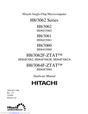
Hitachi H8/3062 Hardware Manual (995 pages)
Single-Chip Microcomputer H8/3062 Series; H8/3062B Series; H8/3062F-ZTAT series; H8/3064F-ZTAT series
Brand:
Hitachi
| Category:
Computer Hardware
| Size: 4.08 MB
Table of Contents
Table of Contents
17
Section 1 Overview
49
Overview
49
Tables
50
Table 1.1 Features
50
Block Diagram
55
Figure 1.1 Block Diagram
55
Figures
55
Pin Description
56
Pin Arrangement
56
Table 1.2 Comparison of H8/3062 Series Pin Arrangements
56
Figure 1.2 Pin Arrangement of H8/3062F-ZTAT, H8/3062F-ZTAT R-Mask Version
57
Figure 1.3 Pin Arrangement of H8/3062F-ZTAT, H8/3062F-ZTAT R-Mask Version
58
Figure 1.4 Pin Arrangement of H8/3064F-ZTAT B-Mask Version
59
H8/3062F-ZTAT B-Mask Version, H8/3064 Mask ROM B-Mask Version
59
Figure 1.5 Pin Arrangement of H8/3064F-ZTAT B-Mask Version
60
Pin Functions
61
Table 1.3 Pin Functions
61
Pin Assignments in each Mode
66
Table 1.4 Pin Assignments in each Mode (FP-100B or TFP-100B, FP-100A)
66
Notes on H8/3062F-ZTAT R-Mask Version
70
Pin Arrangement
70
Product Type Names and Markings
71
Differences between H8/3062F-ZTAT and H8/3062F-ZTAT R-Mask Version
71
Table 1.5 Differences in H8/3062F-ZTAT and H8/3062F-ZTAT R-Mask Version
71
Notes on H8/3064F-ZTAT B-Mask Version, H8/3062F-ZTAT B-Mask Version
72
H8/3061 Mask ROM B-Mask Version, and H8/3060 Mask ROM B-Mask Version
72
Table 1.6 Differences between H8/3062F-ZTAT, H8/3062F-ZTAT R-Mask Version, and On-Chip Mask ROM Versions
72
Pin Arrangement
73
Product Type Names and Markings
73
Table 1.7 Differences in H8/3062F-ZTAT R-Mask Version, H8/3062F-ZTAT B-Mask Version, and H8/3064F-ZTAT B-Mask Version Markings
73
VCL Pin
74
Figure 1.6 H8/3062F-ZTAT B-Mask Version, H8/3064F-ZTAT B-Mask Version, and On-Chip Mask ROM B-Mask Versions
74
Notes on Changeover to On-Chip Mask ROM Versions and On-Chip Mask ROM B-Mask Versions
75
Figure 1.7 Example of Board Pattern Providing for External Capacitor
75
Caution on Crystal Resonator Connection
76
Setting Oscillation Settling Wait Time
76
Section 2 CPU
77
Overview
77
Features
77
Differences from H8/300 CPU
78
CPU Operating Modes
79
Address Space
79
Figure 2.1 CPU Operating Modes
79
Figure 2.2 Memory Map
79
Register Configuration
80
Overview
80
Figure 2.3 CPU Registers
80
2.4.2 General Registers
81
Figure 2.4 Usage of General Registers
81
Figure 2.5 Stack
81
Table 3.2 Registers
81
Control Registers
82
Initial CPU Register Values
83
Data Formats
84
General Register Data Formats
84
Figure 2.6 General Register Data Formats
84
Memory Data Formats
85
Figure 2.7 General Register Data Formats
85
Figure 2.8 Memory Data Formats
86
Instruction Set
87
Instruction Set Overview
87
Table 2.1 Instruction Classification
87
Instructions and Addressing Modes
88
Table 2.2 Instructions and Addressing Modes
88
Tables of Instructions Classified by Function
89
Table 2.3 Data Transfer Instructions
90
Table 2.4 Arithmetic Operation Instructions
91
Table 2.5 Logic Operation Instructions
93
Table 2.6 Shift Instructions
93
Table 2.7 Bit Manipulation Instructions
94
Table 2.8 Branching Instructions
96
Table 2.9 System Control Instructions
97
Basic Instruction Formats
98
Table 2.10 Block Transfer Instruction
98
Notes on Use of Bit Manipulation Instructions
99
Figure 2.9 Instruction Formats
99
Addressing Modes and Effective Address Calculation
101
Addressing Modes
101
Table 2.11 Addressing Modes
101
Table 2.12 Absolute Address Access Ranges
102
Effective Address Calculation
103
Figure 2.10 Memory-Indirect Branch Address Specification
103
Table 2.13 Effective Address Calculation
104
Processing States
107
Overview
107
Program Execution State
107
Figure 2.11 Processing States
107
Exception-Handling State
108
Figure 2.12 Classification of Exception Sources
108
Table 2.14 Exception Handling Types and Priority
108
Exception Handling Operation
109
Figure 2.13 State Transitions
109
Bus-Released State
110
Reset State
110
Figure 2.14 Stack Structure after Exception Handling
110
Power-Down State
111
Basic Operational Timing
111
Overview
111
On-Chip Memory Access Timing
111
On-Chip Supporting Module Access Timing
112
Figure 2.15 On-Chip Memory Access Cycle
112
Figure 2.16 Pin States During On-Chip Memory Access (Address Update Mode 1)
112
Access to External Address Space
113
Figure 2.17 Access Cycle for On-Chip Supporting Modules
113
Figure 2.18 Pin States During Access to On-Chip Supporting Modules
113
Section 3 MCU Operating Modes
115
Overview
115
Operating Mode Selection
115
Table 3.1 Operating Mode Selection
115
Register Configuration
116
Mode Control Register (MDCR)
116
System Control Register (SYSCR)
117
Operating Mode Descriptions
120
Mode 1
120
Mode 2
120
Mode 3
120
Mode 4
120
Mode 5
120
Mode 6
121
Mode 7
121
Pin Functions in each Operating Mode
121
Table 3.3 Pin Functions in each Mode
121
Memory Map in each Operating Mode
122
Comparison of H8/3062 Series Memory Maps
122
Table 3.4 Address Maps in Mode 5
122
Reserved Areas
123
Figure 3.1 Memory Map of H8/3062F-ZTAT, H8/3062F-ZTAT R-Mask Version
124
H8/3062F-ZTAT B-Mask Version, H8/3062 Mask ROM Version, and H8/3062 Mask ROM B-Mask Version in each Operating Mode
124
Figure 3.2 Memory Map of H8/3061 Mask ROM Version and H8/3061 Mask ROM B-Mask Version in each Operating Mode
126
Figure 3.3 Memory Map of H8/3060 Mask ROM Version and H8/3060 Mask ROM B-Mask Version in each Operating Mode
128
Figure 3.4 H8/3064F-ZTAT B-Mask Version and H8/3064 Mask ROM B-Mask Version Memory Map in each Operating Mode
130
Section 4 Exception Handling
133
Overview
133
Exception Handling Types and Priority
133
Exception Handling Operation
133
Table 4.1 Exception Types and Priority
133
Exception Vector Table
134
Figure 4.1 Exception Sources
134
Table 4.2 Exception Vector Table
135
Reset
136
Overview
136
Reset Sequence
136
Figure 4.2 Reset Sequence (Modes 1 and 3)
137
Figure 4.3 Reset Sequence (Modes 2 and 4)
138
Interrupts after Reset
139
Figure 4.4 Reset Sequence (Mode 6)
139
Interrupts
140
Trap Instruction
140
Figure 4.5 Interrupt Sources and Number of Interrupts
140
Stack Status after Exception Handling
141
Figure 4.6 Stack after Completion of Exception Handling
141
Notes on Stack Usage
142
Figure 4.7 Operation When SP Value Is Odd
143
Section 5 Interrupt Controller
145
Overview
145
Features
145
Block Diagram
146
Figure 5.1 Interrupt Controller Block Diagram
146
Pin Configuration
147
Register Configuration
147
Register Descriptions
147
System Control Register (SYSCR)
147
Table 5.1 Interrupt Pins
147
Table 5.2 Interrupt Controller Registers
147
Interrupt Priority Registers a and B (IPRA, IPRB)
148
IRQ Status Register (ISR)
153
IRQ Enable Register (IER)
154
IRQ Sense Control Register (ISCR)
155
Interrupt Sources
156
External Interrupts
156
Figure 5.2 Block Diagram of Interrupts IRQ to IRQ 5
156
Internal Interrupts
157
Interrupt Exception Handling Vector Table
157
Figure 5.3 Timing of Setting of Irqnf
157
Table 5.3 Interrupt Sources, Vector Addresses, and Priority
158
Interrupt Operation
161
Interrupt Handling Process
161
Table 5.4 UE, I, and UI Bit Settings and Interrupt Handling
161
Figure 5.4 Process up to Interrupt Acceptance When UE = 1
162
Figure 5.5 Interrupt Masking State Transitions (Example)
164
Figure 5.6 Process up to Interrupt Acceptance When UE = 0
165
Interrupt Exception Handling Sequence
166
Figure 5.7 Interrupt Exception Handling Sequence
166
Interrupt Response Time
167
Table 5.5 Interrupt Response Time
167
Usage Notes
168
Contention between Interrupt and Interrupt-Disabling Instruction
168
Figure 5.8 Contention between Interrupt and Interrupt-Disabling Instruction
168
Instructions that Inhibit Interrupts
169
Interrupts During EEPMOV Instruction Execution
169
Section 6 Bus Controller
171
Overview
171
Features
171
Block Diagram
172
Figure 6.1 Block Diagram of Bus Controller
172
Pin Configuration
173
Table 6.1 Bus Controller Pins
173
Register Configuration
174
Register Descriptions
174
Bus Width Control Register (ABWCR)
174
Table 6.2 Bus Controller Registers
174
Access State Control Register (ASTCR)
175
Wait Control Registers H and L (WCRH, WCRL)
176
Bus Release Control Register (BRCR)
180
Bus Control Register (BCR)
181
Chip Select Control Register (CSCR)
183
Address Control Register (ADRCR)
184
Operation
185
Area Division
185
Figure 6.2 Access Area Map for each Operating Mode
185
Figure 6.3 Memory Map in 16-Mbyte Mode
186
Version, H8/3062 Mask ROM Version, H8/3061 Mask ROM Version, H8/3062 Mask ROM B-Mask Version, H8/3061 Mask ROM B-Mask Version) (1)
186
Figure 6.3 Memory Map in 16-Mbyte Mode (H8/3060 Mask ROM Version, H8/3060 Mask ROM B-Mask Version) (2)
187
Figure 6.3 Memory Map in 16-Mbyte Mode (H8/3064F-ZTAT B-Mask Version, H8/3064 Mask ROM B-Mask Version) (3)
188
Bus Specifications
189
Table 6.3 Bus Specifications for each Area (Basic Bus Interface)
189
Memory Interfaces
190
Chip Select Signals
190
Figure 6.4 Csn Signal Output Timing (N = 0 to 7)
190
Address Output Method
191
Figure 6.5 Sample Address Output in each Address Update Mode (Basic Bus Interface, 3-State Space)
191
Figure 6.6 Example of Consecutive External Space Accesses in Address Update Mode 2
192
Basic Bus Interface
193
Overview
193
Data Size and Data Alignment
193
Figure 6.7 Access Sizes and Data Alignment Control (8-Bit Access Area)
193
Valid Strobes
194
Figure 6.8 Access Sizes and Data Alignment Control (16-Bit Access Area)
194
Table 6.4 Data Buses Used and Valid Strobes
194
Memory Areas
195
Basic Bus Control Signal Timing
196
Figure 6.9 Bus Control Signal Timing for 8-Bit, Three-State-Access Area
196
Figure 6.10 Bus Control Signal Timing for 8-Bit, Two-State-Access Area
197
Figure 6.11 Bus Control Signal Timing for 16-Bit, Three-State-Access Area
198
Figure 6.12 Bus Control Signal Timing for 16-Bit, Three-State-Access Area
200
Wait Control
203
Figure 6.15 Bus Control Signal Timing for 16-Bit, Two-State-Access Area
203
Figure 6.16 Bus Control Signal Timing for 16-Bit, Two-State-Access Area (3) (Word Access)
203
Figure 6.17 Example of Wait State Insertion Timing
204
Idle Cycle
205
Operation
205
Figure 6.18 Example of Idle Cycle Operation (ICIS1 = 1)
205
Figure 6.19 Example of Idle Cycle Operation (ICIS0 = 1)
206
Figure 6.20 Example of Idle Cycle Operation
206
Pin States in Idle Cycle
207
Bus Arbiter
207
Table 6.5 Pin States in Idle Cycle
207
Operation
208
Figure 6.21 Example of External Bus Master Operation
209
Register and Pin Input Timing
210
Register Write Timing
210
Figure 6.22 ASTCR Write Timing
210
Figure 6.23 DDR Write Timing
210
BREQ Pin Input Timing
211
Figure 6.24 BRCR Write Timing
211
Section 7 I/O Ports
213
Overview
213
Table 7.1 Port Functions
213
Port 1
217
Overview
217
Register Descriptions
217
Figure 7.1 Port 1 Pin Configuration
217
Table 7.2 Port 1 Registers
217
Port 2
220
Overview
220
Figure 7.2 Port 2 Pin Configuration
220
Register Descriptions
221
Table 7.3 Port 2 Registers
221
Table 7.4 Input Pull-Up Transistor States (Port 2)
223
Port 3
224
Overview
224
Register Descriptions
224
Figure 7.3 Port 3 Pin Configuration
224
Table 7.5 Port 3 Registers
224
Port 4
226
Overview
226
Figure 7.4 Port 4 Pin Configuration
226
Register Descriptions
227
Table 7.6 Port 4 Registers
227
Port 5
229
Overview
229
Figure 7.5 Port 5 Pin Configuration
229
Table 7.7 Input Pull-Up Transistor States (Port 4)
229
Register Descriptions
230
Table 7.8 Port 5 Registers
230
Port 6
232
Overview
232
Table 7.9 Input Pull-Up Transistor States (Port 5)
232
Register Descriptions
233
Figure 7.6 Port 6 Pin Configuration
233
Table 7.10 Port 6 Registers
233
Table 7.11 Port 6 Pin Functions in Modes 1 to 5
235
Port 7
236
Overview
236
Figure 7.7 Port 7 Pin Configuration
236
Register Description
237
Table 7.12 Port 7 Data Register
237
Port 8
238
Overview
238
Figure 7.8 Port 8 Pin Configuration
238
Register Descriptions
239
Table 7.13 Port 8 Registers
239
Table 7.14 Port 8 Pin Functions in Modes 1 to 5
241
Table 7.15 Port 8 Pin Functions in Modes 6 and 7
242
Port 9
243
Overview
243
Figure 7.9 Port 9 Pin Configuration
243
Register Descriptions
244
Table 7.16 Port 9 Registers
244
Table 7.17 Port 9 Pin Functions
246
Port a
248
Overview
248
Figure 7.10 Port a Pin Configuration
249
Register Descriptions
250
Table 7.18 Port a Registers
250
Table 7.19 Port a Pin Functions (Modes 1, 2, 6, and 7)
252
Table 7.20 Port a Pin Functions (Modes 3 to 5)
254
Table 7.21 Port a Pin Functions (Modes 1 to 7)
257
Port B
260
Overview
260
Figure 7.11 Port B Pin Configuration
261
Register Descriptions
262
Table 7.22 Port B Registers
262
Table 7.23 Port B Pin Functions (Modes 1 to 5)
264
Table 7.24 Port B Pin Functions (Modes 6 and 7)
266
Section 8 16-Bit Timer
269
Overview
269
Features
269
Table 8.1 16-Bit Timer Functions
270
Block Diagrams
271
Figure 8.1 16-Bit Timer Block Diagram (Overall)
271
Figure 8.2 Block Diagram of Channels 0 and 1
272
Figure 8.3 Block Diagram of Channel 2
273
Pin Configuration
274
Table 8.2 16-Bit Timer Pins
274
Register Configuration
275
Table 8.3 16-Bit Timer Registers
275
Register Descriptions
276
Timer Start Register (TSTR)
276
Timer Synchro Register (TSNC)
277
Timer Mode Register (TMDR)
278
Timer Interrupt Status Register a (TISRA)
281
Timer Interrupt Status Register B (TISRB)
283
Timer Interrupt Status Register C (TISRC)
286
Timer Counters (16TCNT)
288
General Registers (GRA, GRB)
289
Timer Control Registers (16TCR)
290
Timer I/O Control Register (TIOR)
292
Timer Output Level Setting Register C (TOLR)
294
CPU Interface
296
16-Bit Accessible Registers
296
Figure 8.4 16TCNT Access Operation [CPU → 16TCNT (Word)]
296
Figure 8.5 Access to Timer Counter (CPU Reads 16TCNT, Word)
296
Figure 8.6 Access to Timer Counter H (CPU Writes to 16TCNTH, Upper Byte)
297
Figure 8.7 Access to Timer Counter L (CPU Writes to 16TCNTL, Lower Byte)
297
Figure 8.8 Access to Timer Counter H (CPU Reads 16TCNTH, Upper Byte)
297
8-Bit Accessible Registers
298
Figure 8.9 Access to Timer Counter L (CPU Reads 16TCNTL, Lower Byte)
298
Figure 8.10 16TCR Access (CPU Writes to 16TCR)
298
Figure 8.11 16TCR Access (CPU Reads 16TCR)
298
Operation
299
Overview
299
Basic Functions
299
Figure 8.12 Counter Setup Procedure (Example)
300
Figure 8.13 Free-Running Counter Operation
301
Figure 8.14 Periodic Counter Operation
301
Figure 8.15 Count Timing for Internal Clock Sources
302
Figure 8.16 Count Timing for External Clock Sources (When both Edges Are Detected)
302
Figure 8.17 Setup Procedure for Waveform Output by Compare Match (Example)
303
Figure 8.18 0 and 1 Output (TOA = 1, TOB = 0)
304
Figure 8.19 Toggle Output (TOA = 1, TOB = 0)
304
Figure 8.20 Output Compare Output Timing
305
Figure 8.21 Setup Procedure for Input Capture (Example)
306
Figure 8.22 Input Capture (Example)
306
Synchronization
307
Figure 8.23 Input Capture Signal Timing
307
Figure 8.24 Setup Procedure for Synchronization (Example)
308
PWM Mode
309
Figure 8.25 Synchronization (Example)
309
Table 8.4 PWM Output Pins and Registers
309
Figure 8.26 Setup Procedure for PWM Mode (Example)
310
Figure 8.27 PWM Mode (Example 1)
311
Figure 8.28 PWM Mode (Example 2)
312
Phase Counting Mode
313
Figure 8.29 Setup Procedure for Phase Counting Mode (Example)
313
Figure 8.30 Operation in Phase Counting Mode (Example)
314
Figure 8.31 Phase Difference, Overlap, and Pulse Width in Phase Counting Mode
314
Table 8.5 Up/Down Counting Conditions
314
16-Bit Timer Output Timing
315
Figure 8.32 Timing for Setting 16-Bit Timer Output Level by Writing to TOLR
315
Interrupts
316
Setting of Status Flags
316
Figure 8.33 Timing of Setting of IMFA and IMFB by Compare Match
316
Figure 8.34 Timing of Setting of IMFA and IMFB by Input Capture
317
Timing of Clearing of Status Flags
318
Figure 8.35 Timing of Setting of OVF
318
Figure 8.36 Timing of Clearing of Status Flags
318
Interrupt Sources
319
Table 8.6 16-Bit Timer Interrupt Sources
319
Usage Notes
320
Figure 8.37 Contention between 16TCNT Write and Clear
320
Figure 8.38 Contention between 16TCNT Word Write and Increment
321
Figure 8.39 Contention between 16TCNT Byte Write and Increment
322
Figure 8.40 Contention between General Register Write and Compare Match
323
Figure 8.41 Contention between 16TCNT Write and Overflow
324
Figure 8.42 Contention between General Register Read and Input Capture
325
Figure 8.43 Contention between Counter Clearing by Input Capture and Counter Increment
326
Figure 8.44 Contention between General Register Write and Input Capture
327
Table 8.7 (A) 16-Bit Timer Operating Modes (Channel 0)
329
Table 8.7 (B) 16-Bit Timer Operating Modes (Channel 1)
330
Table 8.7 (C) 16-Bit Timer Operating Modes (Channel 2)
331
8-Bit Timers
333
Overview
333
Features
333
Section 9 8-Bit Timers
333
Block Diagram
335
Figure 9.1 Block Diagram of 8-Bit Timer Unit (Two Channels: Group 0)
335
Pin Configuration
336
Table 9.1 8-Bit Timer Pins
336
Register Configuration
337
Table 9.2 8-Bit Timer Registers
337
Register Descriptions
338
Timer Counters (8TCNT)
338
Time Constant Registers a (TCORA)
339
Time Constant Registers B (TCORB)
340
Timer Control Register (8TCR)
341
Timer Control/Status Registers (8TCSR)
344
Table 9.3 Operation of Channels 0 and 1 When Bit ICE Is Set to 1 in 8TCSR1 Register
347
Table 9.4 Operation of Channels 2 and 3 When Bit ICE Is Set to 1 in 8TCSR3 Register
347
CPU Interface
349
8-Bit Registers
349
Figure 9.2 8TCNT Access Operation (CPU Writes to 8TCNT, Word)
349
Figure 9.3 8TCNT Access Operation (CPU Reads 8TCNT, Word)
349
Figure 9.4 8TCNT0 Access Operation (CPU Writes to 8TCNT0, Upper Byte)
349
Figure 9.5 8TCNT1 Access Operation (CPU Writes to 8TCNT1, Lower Byte)
350
Figure 9.6 8TCNT0 Access Operation (CPU Reads 8TCNT0, Upper Byte)
350
Figure 9.7 8TCNT1 Access Operation (CPU Reads 8TCNT1, Lower Byte)
350
Operation
351
8TCNT Count Timing
351
Figure 9.8 Count Timing for Internal Clock Input
351
Compare Match Timing
352
Figure 9.9 Count Timing for External Clock Input (Both-Edge Detection)
352
Figure 9.10 Timing of Timer Output
352
Input Capture Signal Timing
353
Figure 9.11 Timing of Clear by Compare Match
353
Figure 9.12 Timing of Clear by Input Capture
353
Timing of Status Flag Setting
354
Figure 9.13 Timing of Input Capture Input Signal
354
Figure 9.14 CMF Flag Setting Timing When Compare Match Occurs
354
Operation with Cascaded Connection
355
Figure 9.15 CMFB Flag Setting Timing When Input Capture Occurs
355
Figure 9.16 Timing of OVF Setting
355
Input Capture Setting
358
Interrupt
359
Interrupt Sources
359
Table 9.5 Types of 8-Bit Timer Interrupt Sources and Priority Order
359
Table 9.6 8-Bit Timer Interrupt Sources
359
A/D Converter Activation
360
8-Bit Timer Application Example
360
Figure 9.17 Example of Pulse Output
360
Usage Notes
361
Contention between 8TCNT Write and Clear
361
Figure 9.18 Contention between 8TCNT Write and Clear
361
Contention between 8TCNT Write and Increment
362
Figure 9.19 Contention between 8TCNT Write and Increment
362
Contention between TCOR Write and Compare Match
363
Figure 9.20 Contention between TCOR Write and Compare Match
363
Contention between TCOR Read and Input Capture
364
Figure 9.21 Contention between TCOR Read and Input Capture
364
Contention between Counter Clearing by Input Capture and Counter Increment
365
Figure 9.22 Contention between Counter Clearing by Input Capture and Counter Increment
365
Contention between TCOR Write and Input Capture
366
Figure 9.23 Contention between TCOR Write and Input Capture
366
Contention between 8TCNT Byte Write and Increment in 16-Bit Count Mode (Cascaded Connection)
367
Figure 9.24 Contention between 8TCNT Byte Write and Increment in 16-Bit Count Mode
367
Contention between Compare Matches a and B
368
8TCNT Operation and Internal Clock Source Switchover
368
Table 9.7 Timer Output Priority Order
368
Table 9.8 Internal Clock Switchover and 8TCNT Operation
369
Section 10 Programmable Timing Pattern Controller (TPC)
371
Overview
371
Features
371
Block Diagram
372
Figure 10.1 TPC Block Diagram
372
Pin Configuration
373
Table 10.1 TPC Pins
373
Register Configuration
374
Table 10.2 TPC Registers
374
Register Descriptions
375
Port a Data Direction Register (PADDR)
375
Port a Data Register (PADR)
375
Port B Data Direction Register (PBDDR)
376
Port B Data Register (PBDR)
376
Next Data Register a (NDRA)
377
Next Data Register B (NDRB)
379
Next Data Enable Register a (NDERA)
381
Next Data Enable Register B (NDERB)
382
TPC Output Control Register (TPCR)
383
TPC Output Mode Register (TPMR)
385
Operation
387
Overview
387
Figure 10.2 TPC Output Operation
387
Table 10.3 TPC Operating Conditions
387
Output Timing
388
Figure 10.3 Timing of Transfer of Next Data Register Contents and Output (Example)
388
Normal TPC Output
389
Figure 10.4 Setup Procedure for Normal TPC Output (Example)
389
Figure 10.5 Normal TPC Output Example (Five-Phase Pulse Output)
390
Non-Overlapping TPC Output
391
Figure 10.6 Setup Procedure for Non-Overlapping TPC Output (Example)
391
Figure 10.7 Non-Overlapping TPC Output Example
392
TPC Output Triggering by Input Capture
393
Figure 10.8 TPC Output Triggering by Input Capture (Example)
393
Usage Notes
394
Operation of TPC Output Pins
394
Note on Non-Overlapping Output
394
Figure 10.9 Non-Overlapping TPC Output
394
Figure 10.10 Non-Overlapping Operation and NDR Write Timing
395
Section 11 Watchdog Timer
397
Overview
397
Features
397
Block Diagram
398
Pin Configuration
398
Figure 11.1 WDT Block Diagram
398
Table 11.1 WDT Pin
398
Register Configuration
399
Register Descriptions
399
Timer Counter (TCNT)
399
Table 11.2 WDT Registers
399
Timer Control/Status Register (TCSR)
400
Reset Control/Status Register (RSTCSR)
402
Notes on Register Rewriting
403
Figure 11.2 Format of Data Written to TCNT and TCSR
403
Figure 11.3 Format of Data Written to RSTCSR
404
Table 11.3 Read Addresses of TCNT, TCSR, and RSTCSR
404
Operation
405
Watchdog Timer Operation
405
Figure 11.4 Operation in Watchdog Timer Mode
405
Interval Timer Operation
406
Timing of Setting of Overflow Flag (OVF)
406
Figure 11.5 Interval Timer Operation
406
Figure 11.6 Timing of Setting of OVF
406
Timing of Setting of Watchdog Timer Reset Bit (WRST)
407
Figure 11.7 Timing of Setting of WRST Bit and Internal Reset
407
Interrupts
408
Usage Notes
408
Figure 11.8 Contention between TCNT Write and Count up
408
Section 12 Serial Communication Interface
409
Overview
409
Features
409
Block Diagram
411
Figure 12.1 SCI Block Diagram
411
Pin Configuration
412
Table 12.1 SCI Pins
412
Register Configuration
413
Table 12.2 SCI Registers
413
Register Descriptions
414
Receive Shift Register (RSR)
414
Receive Data Register (RDR)
414
Transmit Shift Register (TSR)
415
Transmit Data Register (TDR)
415
Serial Mode Register (SMR)
416
Serial Control Register (SCR)
419
Serial Status Register (SSR)
423
Bit Rate Register (BRR)
428
Table 12.3 Examples of Bit Rates and BRR Settings in Asynchronous Mode
429
Table 12.4 Examples of Bit Rates and BRR Settings in Synchronous Mode
432
Table 12.5 Maximum Bit Rates for Various Frequencies (Asynchronous Mode)
434
Table 12.6 Maximum Bit Rates with External Clock Input (Asynchronous Mode)
435
Operation
436
Overview
436
Table 12.7 Maximum Bit Rates with External Clock Input (Synchronous Mode)
436
Table 12.8 SMR Settings and Serial Communication Formats
438
Table 12.9 SMR and SCR Settings and SCI Clock Source Selection
438
Operation in Asynchronous Mode
439
Figure 12.2 Data Format in Asynchronous Communication (Example: 8-Bit Data with Parity and 2 Stop Bits)
439
Table 12.10 Serial Communication Formats (Asynchronous Mode)
440
Figure 12.3 Phase Relationship between Output Clock and Serial Data (Asynchronous Mode)
441
Figure 12.4 Sample Flowchart for SCI Initialization
442
Figure 12.5 Sample Flowchart for Transmitting Serial Data
443
Figure 12.6 Example of SCI Transmit Operation in Asynchronous Mode (8-Bit Data with Parity and One Stop Bit)
444
Figure 12.7 Sample Flowchart for Receiving Serial Data
445
Table 12.11 Receive Error Conditions
447
Multiprocessor Communication
448
Figure 12.8 Example of SCI Receive Operation (8-Bit Data with Parity and One Stop Bit)
448
Figure 12.9 Example of Communication Among Processors Using Multiprocessor Format (Sending Data H'AA to Receiving Processor A)
449
Figure 12.10 Sample Flowchart for Transmitting Multiprocessor Serial Data
450
Figure 12.11 Example of SCI Transmit Operation (8-Bit Data with Multiprocessor Bit and One Stop Bit)
451
Figure 12.12 Sample Flowchart for Receiving Multiprocessor Serial Data
452
Figure 12.13 Example of SCI Receive Operation (8-Bit Data with Multiprocessor Bit and One Stop Bit)
454
Synchronous Operation
455
Figure 12.14 Data Format in Synchronous Communication
455
Figure 12.15 Sample Flowchart for SCI Initialization
456
Figure 12.16 Sample Flowchart for Serial Transmitting
457
Figure 12.17 Example of SCI Transmit Operation
458
Figure 12.18 Sample Flowchart for Serial Receiving
459
Figure 12.19 Example of SCI Receive Operation
461
Figure 12.20 Sample Flowchart for Simultaneous Serial Transmitting and Receiving
462
SCI Interrupts
463
Table 12.12 SCI Interrupt Sources
463
Usage Notes
464
Notes on Use of SCI
464
Table 12.13 SSR Status Flags and Transfer of Receive Data
464
Figure 12.21 Receive Data Sampling Timing in Asynchronous Mode
465
Figure 12.22 Example of Synchronous Transmission
466
Figure 12.23 Operation When Switching from SCK Pin Function to Port Pin Function
467
Figure 12.24 Operation When Switching from SCK Pin Function to Port Pin Function (Example of Preventing Low-Level Output)
468
Section 13 Smart Card Interface
469
Overview
469
Features
469
Block Diagram
470
Pin Configuration
470
Figure 13.1 Block Diagram of Smart Card Interface
470
Table 13.1 Smart Card Interface Pins
470
Register Configuration
471
Table 13.2 Smart Card Interface Registers
471
Register Descriptions
472
Smart Card Mode Register (SCMR)
472
Serial Status Register (SSR)
474
Serial Mode Register (SMR)
475
Serial Control Register (SCR)
476
Operation
477
Overview
477
Pin Connections
477
Data Format
478
Figure 13.2 Smart Card Interface Connection Diagram
478
Figure 13.3 Smart Card Interface Data Format
479
Register Settings
480
Table 13.3 Smart Card Interface Register Settings
480
Clock
482
Table 13.4 N-Values of CKS1 and CKS0 Settings
482
Table 13.5 Bit Rates (Bits/S) for Various BRR Settings (When N = 0)
482
Table 13.6 BRR Settings for Typical Bit Rates (Bits/S) (When N = 0)
483
Table 13.7 Maximum Bit Rates for Various Frequencies (Smart Card Interface Mode)
483
Transmitting and Receiving Data
484
Figure 13.4 Timing of TEND Flag Setting
485
Figure 13.5 Sample Transmission Processing Flowchart
486
Figure 13.6 Relation between Transmit Operation and Internal Registers
487
Figure 13.7 Timing of TEND Flag Setting
487
Figure 13.8 Sample Reception Processing Flowchart
488
Figure 13.9 Timing for Fixing Cock Output
489
Table 13.8 Smart Card Interface Mode Operating States and Interrupt Sources
489
Figure 13.10 Procedure for Stopping and Restarting the Clock
490
Usage Notes
491
Figure 13.11 Receive Data Sampling Timing in Smart Card Interface Mode
491
Figure 13.12 Retransmission in SCI Receive Mode
493
Figure 13.13 Retransmission in SCI Transmit Mode
493
Advertisement
Hitachi H8/3062 Hardware Manual (939 pages)
Single-Chip Microcomputer
Brand:
Hitachi
| Category:
Computer Hardware
| Size: 2.98 MB
Table of Contents
Table of Contents
11
Section 1 Overview
26
Block Diagram
31
Pin Description
32
Pin Arrangement
32
Pin Functions
37
Pin Assignments in each Mode
41
Notes on H8/3062F-ZTAT R-Mask Version
45
Pin Arrangement
45
Product Type Names and Markings
46
Differences between H8/3062F-ZTAT and H8/3062F-ZTAT R-Mask Version
46
Notes on H8/3064F-ZTAT and H8/3062F-ZTAT A-Mask Version
47
Pin Arrangement
47
Product Type Names and Markings
48
Note on Changeover to Mask ROM Version
50
VCL Pin
50
Setting Oscillation Settling Wait Time
51
Caution on Crystal Resonator Connection
51
Cpu
52
Overview
52
Features
52
Differences from H8/300 CPU
53
CPU Operating Modes
53
Address Space
54
Register Configuration
55
Overview
55
2.4.2 General Registers
56
Control Registers
57
Initial CPU Register Values
58
Data Formats
59
General Register Data Formats
59
Memory Data Formats
60
Instruction Set
62
Instruction Set Overview
62
Instructions and Addressing Modes
63
Tables of Instructions Classified by Function
64
2.6.4 Basic Instruction Formats
73
Notes on Use of Bit Manipulation Instructions
74
Addressing Modes and Effective Address Calculation
76
Addressing Modes
76
Effective Address Calculation
78
Processing States
82
Overview
82
Program Execution State
82
Exception-Handling State
83
Exception Handling Operation
84
Bus-Released State
85
Reset State
85
Power-Down State
86
Basic Operational Timing
86
Overview
86
On-Chip Memory Access Timing
86
On-Chip Supporting Module Access Timing
87
Access to External Address Space
88
MCU Operating Modes
89
Overview
89
Operating Mode Selection
89
Register Configuration
90
Mode Control Register (MDCR)
90
System Control Register (SYSCR)
91
Operating Mode Descriptions
93
Mode 1
93
Mode 2
93
Mode 3
94
Mode 4
94
Mode 5
94
Mode 7
94
Pin Functions in each Operating Mode
95
Memory Map in each Operating Mode
96
Comparison of H8/3062 Series Memory Maps
96
Reserved Areas
97
Exception Handling
106
Overview
106
Exception Handling Types and Priority
106
Exception Handling Operation
106
Exception Vector Table
107
Reset
109
Reset Sequence
109
Interrupts after Reset
112
Interrupts
113
Trap Instruction
113
Stack Status after Exception Handling
114
Notes on Stack Usage
115
Overview
117
Interrupt Controller
117
Features
117
Block Diagram
118
Pin Configuration
119
Register Configuration
119
Register Descriptions
119
System Control Register (SYSCR)
119
Interrupt Priority Registers a and B (IPRA, IPRB)
120
IRQ Status Register (ISR)
125
IRQ Enable Register (IER)
126
IRQ Sense Control Register (ISCR)
127
Interrupt Sources
128
External Interrupts
128
Internal Interrupts
129
Interrupt Exception Handling Vector Table
129
Interrupt Operation
133
Interrupt Handling Process
133
Interrupt Exception Handling Sequence
138
Interrupt Response Time
139
Usage Notes
140
Contention between Interrupt and Interrupt-Disabling Instruction
140
Instructions that Inhibit Interrupts
141
Interrupts During EEPMOV Instruction Execution
141
Bus Controller
142
Overview
142
Features
142
Block Diagram
143
Pin Configuration
144
Register Configuration
145
Register Descriptions
145
Bus Width Control Register (ABWCR)
145
Access State Control Register (ASTCR)
146
Wait Control Registers H and L (WCRH, WCRL)
147
Bus Release Control Register (BRCR)
151
Bus Control Register (BCR)
152
Chip Select Control Register (CSCR)
154
Address Control Register (ADRCR)
155
Operation
156
Area Division
156
Bus Specifications
159
Memory Interfaces
160
Address Output Method
161
Basic Bus Interface
163
Overview
163
Data Size and Data Alignment
163
Valid Strobes
164
Memory Areas
165
Basic Bus Control Signal Timing
166
Wait Control
173
Idle Cycle
175
Operation
175
Pin States in Idle Cycle
177
Bus Arbiter
177
Operation
178
Register and Pin Input Timing
180
Register Write Timing
180
BREQ Pin Input Timing
181
I/O Ports
182
Overview
182
Port 1
186
Overview
186
Register Descriptions
186
Port 2
189
Overview
189
Register Descriptions
190
Port 3
193
Overview
195
Register Descriptions
199
Port 4
201
Overview
201
Port 5
201
Overview
205
Port 6
205
Port 7
205
Register Description
206
Port 8
207
Overview
207
Register Descriptions
213
Overview
217
Port a
217
Register Descriptions
219
Port B
229
Overview
229
Register Descriptions
231
16-Bit Timer
237
Overview
237
Features
237
Block Diagrams
239
Pin Configuration
242
Register Configuration
243
Register Descriptions
244
Timer Start Register (TSTR)
244
Timer Synchro Register (TSNC)
245
Timer Mode Register (TMDR)
246
Timer Interrupt Status Register a (TISRA)
249
Timer Interrupt Status Register B (TISRB)
251
Timer Interrupt Status Register C (TISRC)
254
Timer Counters (16TCNT)
256
General Registers (GRA, GRB)
257
Timer Control Registers (16TCR)
258
Timer I/O Control Register (TIOR)
260
Timer Output Level Setting Register C (TOLR)
262
CPU Interface
264
16-Bit Accessible Registers
264
8-Bit Accessible Registers
266
Operation
267
Overview
267
Basic Functions
267
Synchronization
275
PWM Mode
277
Phase Counting Mode
281
16-Bit Timer Output Timing
283
Interrupts
284
Setting of Status Flags
284
Timing of Clearing of Status Flags
286
Usage Notes
288
8-Bit Timers
300
Overview
300
Features
300
Block Diagram
302
Pin Configuration
303
Register Configuration
304
Register Descriptions
305
Timer Counters (8TCNT)
305
Time Constant Registers a (TCORA)
306
Time Constant Registers B (TCORB)
307
Timer Control Register (8TCR)
308
Timer Control/Status Registers (8TCSR)
311
CPU Interface
316
8-Bit Registers
316
Operation
318
8TCNT Count Timing
318
Compare Match Timing
319
Input Capture Signal Timing
320
Timing of Status Flag Setting
321
Operation with Cascaded Connection
322
Input Capture Setting
325
Interrupt
326
Interrupt Sources
326
A/D Converter Activation
327
8-Bit Timer Application Example
327
Usage Notes
328
Contention between 8TCNT Write and Clear
328
Contention between 8TCNT Write and Increment
329
Contention between TCOR Write and Compare Match
330
Contention between TCOR Read and Input Capture
331
Contention between Counter Clearing by Input Capture and Counter Increment
332
Contention between TCOR Write and Input Capture
333
Contention between 8TCNT Byte Write and Increment in 16-Bit Count Mode (Cascaded Connection)
334
Contention between Compare Matches a and B
335
8TCNT Operation and Internal Clock Source Switchover
335
Section 10 Programmable Timing Pattern Controller (TPC)
338
Overview
338
Features
338
Block Diagram
339
Pin Configuration
340
Register Configuration
341
Register Descriptions
342
Port a Data Direction Register (PADDR)
342
Port a Data Register (PADR)
342
Port B Data Direction Register (PBDDR)
343
Port B Data Register (PBDR)
343
Next Data Register a (NDRA)
344
Next Data Register B (NDRB)
346
Next Data Enable Register a (NDERA)
348
Next Data Enable Register B (NDERB)
349
TPC Output Control Register (TPCR)
350
TPC Output Mode Register (TPMR)
352
Operation
354
Overview
354
Output Timing
355
Normal TPC Output
356
Non-Overlapping TPC Output
358
TPC Output Triggering by Input Capture
360
Usage Notes
361
Operation of TPC Output Pins
361
Note on Non-Overlapping Output
361
Share and save
Advertisement
Related Products
Hitachi H8/3061
Hitachi H8/3062F-ZTAT
Hitachi H8/3064F-ZTAT
Hitachi H8/3060
Hitachi H8/3064B
Hitachi H8/3062B
Hitachi H8/3061B
Hitachi H8/3060B
Hitachi H8/3021
Hitachi H8/3048 Series
Hitachi Categories
Projector
Air Conditioner
Drill
Power Tool
LCD TV
More Hitachi Manuals
Login
Sign In
OR
Sign in with Facebook
Sign in with Google
Upload manual
Upload from disk
Upload from URL