Sign In
Upload
Manuals
Brands
Datalogic Manuals
Media Converter
AMT58 Series
Datalogic AMT58 Series Manuals
Manuals and User Guides for Datalogic AMT58 Series. We have
5
Datalogic AMT58 Series manuals available for free PDF download: Manual, Instruction Manual, Mounting Instructions
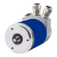
Datalogic AMT58 Series Manual (435 pages)
Absolute Encoders
Brand:
Datalogic
| Category:
Media Converter
| Size: 15 MB
Table of Contents
Italiano
3
Table of Contents
3
Norme DI Sicurezza
9
Identificazione
11
Encoder con Asse Sporgente
12
Fissaggio con Graffe (Codice ST-58-KIT)
12
Fissaggio Standard
12
Istruzioni DI Montaggio
12
Fissaggio con Campana (Codice ST-58-FLNG)
13
Amt58-H15
14
Encoder con Asse Cavo
14
Connessioni Elettriche
15
Coperchio Encoder
15
Collegamento Messa a Terra
16
Coperchio con Pressacavi
16
Collegamento Della Calza
17
Coperchio con Connettori M12
17
LED DI Diagnostica
18
Resistenza DI Terminazione: RT
18
Indirizzo Nodo: DIP B
20
Modifica Della Risoluzione Fisica
21
Quick Reference
21
Risoluzione Fisica Dell'encoder
21
Utilizzo con Le Impostazioni DI Default
23
File EDS
24
Funzionamento a Stati
24
Interfaccia Canopen
24
Stato Inizialization
24
Stato Operational
25
Stato Pre-Operational
25
Stato Stopped
25
COB-ID Previsti O Riconosciuti
26
Tipi DI Messaggi
26
Messaggi DI Boot-Up
27
Messaggi NMT
27
PDO1 Cyclic Mode: Trasmissione Ciclica Della Posizione
28
PDO2 E PDO3 Sync Mode: Trasmissione Sincrona Della Posizione
28
PDO4 Cyclic Mode: Trasmissione Ciclica Della Velocità
28
Messaggi SDO
29
Command
30
1000-00 Tipo DI Dispositivo
31
1001-00 Registro Errori
31
1003 Campo Errori Predefinito
31
1005-00 COB-ID Messaggi Sync
31
Dizionario Oggetti
31
Oggetti Standard (DS 301)
31
00 Guard Time
32
00 Life Time Factor
32
00 Versione Software
32
1008-00 Nome del Costruttore
32
1009-00 Versione Hardware
32
1011-01 Parametri DI Default
33
1015-00 Inhibit Time EMCY
34
1018 Informazioni DI Identificazione
34
1800 Parametri PDO1
34
1801 Parametri PDO2
35
1802 Parametri PDO3
35
1803 Parametri PDO4
36
1A00-01 Mappatura PDO1
36
1A01-01 Mappatura PDO2
36
1A02-01 Mappatura PDO3
36
1A03-01 Mappatura PDO4
36
2104-00 Limit Switch Min
37
2105-00 Limit Switch Max
37
3000-00 Velocità Trasmissione Dati
37
3001-00 Node-ID
39
3005-00 Formato Velocità
39
3006-00 Valore Della Velocità
39
6000-00 Parametri Operativi
40
Direzione DI Conteggio
40
Funzione DI Scaling
40
6001-00 Informazioni Per Giro
41
6002-00 Risoluzione Totale
41
6003-00 Valore DI Preset
42
6200-00 Cyclic Timer
43
6500-00 Stato Operativo
43
Direzione Conteggio
43
Funzione DI Scaling
43
6501-00 Informazioni Per Giro Fisiche
44
6502-00 Numero DI Giri Fisico
44
6504-00 Allarmi Supportati
44
6506-00 Warning Supportati
44
6507-00 Versione Profilo E Software
44
Limit Switch Max
44
Limit Switch Min
44
Stato Operativo Attuale
44
00 Numero DI Serie
45
01 Valore DI Offset del Costruttore
45
6508-00 Tempo DI Lavoro Dispositivo
45
6509-00 Valore DI Offset
45
Messaggi DI Avvertenza
46
Messaggi Emergenza
46
Programmazione
48
English
169
About this Manual
172
Manual Conventions
172
Preface
172
Reseller Technical Support
173
Support through the Website
173
Technical Support
173
Glossary of Profinet Terms
174
List of Abbreviations
178
Chapter 1. Safety Summary
181
Safety
181
Electrical Safety
181
Mechanical Safety
182
Chapter 2. Identification
183
Chapter 3. Mechanical Installation
184
Solid Shaft Encoders
184
Customary Installation
184
Installation Using Fixing Clamps (Code ST-58-KIT)
185
Installation Using a Flange (Code ST-58-FLNG)
185
Hollow Shaft Encoders
186
Amt-58-H15
186
Chapter 4. Electrical Connections
187
PWR Power Supply Connector
188
P1 Port1 and P2 Port2 Connectors
188
Network Configuration: Cables, Hubs, Switches
188
Line Termination
189
MAC Address and IP Address
189
Ground Connection
189
Diagnostic Leds
190
States
192
SETUP State
192
NW_INIT State
192
WAIT_PROCESS State
192
IDLE State
192
PROCESS_ACTIVE State
192
ERROR State
192
EXCEPTION State
192
Chapter 5. Getting Started
193
Quick Start Information
193
Setting the Resolution and the Scaling Function
194
Reading the Position
194
Setting and Executing the Preset
194
Configuring the Encoder with Siemens TIA PORTAL V15
195
About TIA Portal
195
Project Overview
195
Device View
197
Network View
197
Topology View
198
Network and Communication Settings
198
MAC Address
198
Installing the Encoder under TIA Portal Environment
199
Description of the GSDML File
199
Installing the GSDML File
200
Adding a Node to the Project
201
Establishing the Bus Connection
202
Inserting the Telegrams
203
Module Parameters
204
Device Name and IP Address at Delivery
205
Setting the Device Name and the IP Address
206
Compiling and Transferring the Project
207
Establishing an Online Connection (Online Mode)
208
Closing an Online Connection
209
Diagnostics
210
Resetting the Parameters to the Default Factory Values
211
TO Technology Objects
214
Properties of a Technology Object (TO)
214
Installing the Encoder as a Technology Object (TO)
214
Downloading the Project and Going Online
218
Enabling the Encoder
219
Setting and Activating the Preset Value
222
Chapter 6. Profinet Interface
223
A Brief Introduction to Profinet
223
Profinet Encoders from Datalogic
224
Overview of the Encoder Profiles
224
Application Class Definition
225
Application Class 3
225
Application Class 4
225
Encoder Object Model
226
Encoder Object Architecture
227
Chapter 7. Profinet Io Data Description
228
Telegrams
228
Standard Telegram 81
228
Telegram 860
228
Chapter 8. Cyclic Data Exchange - Std Signals
230
List of the Available Standard Signals
232
G1_Xist1
232
G1_Xist2
233
G1_Xist1_Preset_Value
234
Stw2_Enc
235
Control by PLC
235
Controller Sign-Of-Life
235
Zsw2_Enc
236
Control Requested
236
Encoder Sign-Of-Life
236
G1_Stw
237
Home Position Mode
237
Request Set/Shift of Home Position
238
Request Absolute Value Cyclically
239
Activate Parking Sensor
239
Acknowledging a Sensor Error
239
G1_Zsw
240
Nist_B
240
Error Codes in G1_XIST2
241
Chapter 9. Encoder Parameters
242
User Parameter Data
242
Type of Encoder
243
Code Sequence
243
Class 4 Functionality
244
G1_XIST1 Preset Control
244
Scaling Function Control
245
Alarm Channel Control
245
Compatibility Mode
246
Scaling Function Parameters
247
Measuring Units / Revolution
247
Total Measuring Range
248
Maximum Tolerated Failures of Master Sign-Of-Life
249
Velocity Measuring Unit
249
Red Zone
250
Chapter 10. Real-Time Class Communication
252
Real-Time Classes in PROFINET IO
252
Real-Time Class 2 (RT2) - Not Synchronized
252
Real-Time Class 3 (IRT_TOP) (RT3)
252
Setting an Isochronous Communication
253
Ob61
257
PIP (Process Image Partition)
257
Consistency
257
Chapter 11. Encoder Replacement Using Lldp
258
Chapter 12. Media Redundancy Protocol (Mrp)
260
Setting MRP Roles
261
Configuring the Network Topology
262
Interconnecting the Ports in the Inspector Window
263
Chapter 13 Encoder State Machine
264
Normal Operation Diagram
265
Preset Diagram
266
Parking Sensor Diagram
267
Error Diagram
268
Acknowledgment of Acknowledgeable Sensor Error
268
Acknowledgment of Not Acknowledgeable Sensor Error
269
Chapter 14. Integrated Web Server
270
Web Server Home Page
271
Encoder Position and Speed
272
Specific Notes on Using Internet Explorer
273
Encoder Information (Profinet Parameters)
273
Setting the Parameters
274
Setting and Activating the Preset
276
Firmware Upgrade
278
Chapter 15. Default Parameter List
283
Advertisement
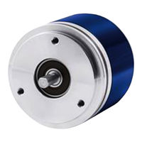
Datalogic AMT58 Series Instruction Manual (59 pages)
Brand:
Datalogic
| Category:
Media Converter
| Size: 0 MB
Table of Contents
Table of Contents
3
Norme DI Sicurezza
7
Identification
9
Mounting Instructions
10
Solid Shaft Encoders
10
Customary Installation
10
Fissaggio con Graffe (Codice ST-58-KIT)
10
Installation Using a Flange (Code ST-58-FLNG)
11
Hollow Shaft Encoders
12
Amt58-H15
12
Electrical Connections
13
Connection Cap
13
Ground Connection
14
Connection Cap with
14
Connection Cap with M12 Connectors
15
Connection of the Shield
15
Baud Rate: DIP a
16
Node Address: DIP B
17
Diagnostic LEDS
18
Bus Termination
18
Quick Reference (Using Rsnetworx)
19
Import EDS File
19
Adding a Node to the Project
20
Encoder Parameters Configuration
21
Save Parameter with Rsnetworx
24
Using Scanner Module
25
Encoder Parameters
28
Position
28
Position Sensor Type
28
Counting Direction
28
Scaling Function Control
28
Measuring Units/Rev
28
Total Measuring Range
29
Preset Value
29
Physical Resolution/Revolution
29
Physical Number of Revolutions
29
Alarms
29
Supported Alarms
30
Offset Value
30
Velocity Value
30
Velocity Format
30
Dip Switch
30
Data Tx in Poll Mode
30
Data Tx in Cos/Cyclic Mode
31
Alarm Flags
31
Delta for COS
31
Auto-Save Parameters
31
Devicenet Interface
32
EDS File
32
Communication Messages
32
I/O Messages (Msg Group 1)
34
Explicit Messages (Msg Group 2)
35
Duplicate MAC-ID Check
36
Error Messages
37
Explicit Messages Connection
39
Message Data Transfer
40
Object Dictionary
41
Class 01H: Identity Object
41
Vendor-ID
42
Device Type
42
Product Code
42
Revision
42
Status
42
Serial Number
43
Product Name
43
Class 03H: Devicenet Object
44
Node Address
44
Baud Rate
44
Bus-Off Interrupt
44
Bus-Off Counter
44
Allocation Information
44
Class 05H: Connection Object
45
05-Inst-01 Connection Status
45
05-Inst-02 Instance Type
45
05-Inst-03 Transportclass_Trigger
45
05-Inst-04 Produced Connection ID
45
05-Inst-05 Consumed Connection ID
45
05-Inst-06 Initial Comm. Characteristics
45
05-Inst-07 Produced Connection Size
47
05-Inst-08 Consumed Connection Size
47
05-Inst-09 Expected Packet Rate
47
05-Inst-0C Watchdog Time-Out Action
47
05-Inst-0D Produced Connection Path Length
47
05-Inst-0E Produced Connection Path
47
05-Inst-0F Consumed Connection Path Length
47
05-Inst-10 Consumed Connection Path
48
05-Inst-11 Production Inhibit Time
48
Class 23H: Position Sensor Object
49
Position Value
49
23-01-0B Device Type
49
23-01-0C Code Sequence
49
23-01-0E Scaling Function Control
49
Resolution Per Revolution
51
Total Measuring Range
51
Preset Value
52
Delta for COS
52
Velocity Value
52
Velocity Format
52
23-01-2A Hardware Counts Per Revolution
52
23-01-2B Hardware Number of Turns
52
23-01-2C Alarms
52
23-01-2D Supported Alarms
53
23-01-2E Alarm Flags
53
Offset
53
Dip Switch
53
Data Tx in Poll Mode
53
Data Tx in Cos/Cyclic Mode
54
Auto-Save Parameters
54
Class 2Bh: Acknowledge Handler Object
55
01-01 Acknowledge Timer
55
01-02 Retry Limit
55
01-03 Connection Instance of COS
55
Setup
56
Read and Set Parameters
56
Set 23-01-13 Preset Value
57
Save Parameter
58
Close Master/Slave Connection
58
Set Cyclic Mode Without Velocity
59
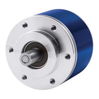
Datalogic AMT58 Series Instruction Manual (63 pages)
EtherCAT Absolute Encoders
Brand:
Datalogic
| Category:
Media Converter
| Size: 3 MB
Table of Contents
Table of Contents
3
Safety Summary
8
Safety
8
Electrical Safety
8
Mechanical Safety
9
Identification
10
Mechanical Installation
11
Solid Shaft Encoders
11
Customary Installation
11
Installation Using Fixing Clamps (Code LKM-386)
11
Installation Using a Mounting Bell (Code ST-58-FLNG)
12
Hollow Shaft Encoders
13
Amt58-H15
13
Electrical Connections
14
M12 Connectors
14
Ground Connection
15
Diagnostic Leds
15
Quick Reference (Twincat)
16
System Configuration Using Twincat Software System from Beckhoff
16
Setting the Network Card
16
Add New I/O Modules (Boxes)
18
Synchronous with SM3
23
Synchronous with DC (SYNC0)
24
Process Data Objects
25
COE Object Dictionary
26
Online Data
27
Eeprom Upgrade
28
Firmware Upgrade
33
Ethercat® Interface
37
Basic Information on Ethercat® Protocol
37
Data Transfer
38
ISO/OSI Layer Model
38
Topology
39
Line Termination
40
Addressing
40
Communication Mode
41
Freerun
42
Synchronous with DC SYNC0
44
Ethercat State Machine (ESM)
45
Slave Configuration
46
Timing and Synchronization
47
Sync Manager
47
Buffered Mode (3-Buffer Mode)
47
Mailbox Mode (1-Buffer Mode)
47
Canopen over Ethercat (Coe)
48
XML File
48
Process Data Objects (PDO)
50
Object Dictionary
52
Standard Objects
52
1000-00 Device Type
52
1008-00 Manufacturer Device Name
52
1009-00 Hardware Version
52
100A-00 Software Version
53
1010-01 Store Parameters
53
1011-01 Restore Default Parameters
53
1018 Identification Object
54
Vendor Number
54
Product Number
54
Revision Number
54
Serial Number
54
1A00-01 PDO Mapping Parameter
54
1C00 Sync Manager Communication Type
54
SM Mailbox Receive (SM0)
54
SM Mailbox Send (SM1)
54
SM PDO Output (SM2)
54
Sync Type
55
Cycle Time
55
Shift Time
55
Sync Modes Supported
55
Minimum Cycle Time
55
Calc and Copy Time
55
Device Profile Objects
56
6000-00 Operating Parameters
56
Code Sequence
56
Scaling Function
56
6001-00 Counts Per Revolution
56
6002-00 Total Resolution
57
6003-00 Preset Value
58
6004-00 Position Value
60
6500-00 Operating Status
60
Code Sequence
60
Scaling Function
60
6501-00 Hardware Counts Per Revolution
61
6502-00 Hardware Number of Turns
61
6503-00 Errors
61
6504-00 Supported Errors
61
6505-00 Warnings
61
6506-00 Supported Warnings
61
6509-00 Offset Value
61
SDO Abort Codes
62
Emergency Error Codes
62
AL Status Error Codes
62
Default Parameters List
63
Advertisement
Datalogic AMT58 Series Manual (2 pages)
Brand:
Datalogic
| Category:
Media Converter
| Size: 0 MB
Table of Contents
Mounting Instructions
1
Safety
2
Electrical Safety
2
Mechanical Safety
2
Warranty
2
Datalogic AMT58 Series Mounting Instructions (2 pages)
Brand:
Datalogic
| Category:
Media Converter
| Size: 0 MB
Advertisement
Related Products
Datalogic AMT58*-PN Series
Datalogic AMT58-PB Series
Datalogic Profibus AMT58 13x12 PB Series
Datalogic AMT58 16x14 CB Series
Datalogic AMT58-H15 13x12 CB
Datalogic AMT58-H15 16x14 CB
Datalogic A20
Datalogic Jota A6 Touch
Datalogic Arex 420
Datalogic Arex 400
Datalogic Categories
Barcode Reader
Scanner
Accessories
PDA
Handhelds
More Datalogic Manuals
Login
Sign In
OR
Sign in with Facebook
Sign in with Google
Upload manual
Upload from disk
Upload from URL