Sign In
Upload
Manuals
Brands
Datalogic Manuals
Media Converter
AMT58*-PN Series
Datalogic AMT58*-PN Series Manuals
Manuals and User Guides for Datalogic AMT58*-PN Series. We have
1
Datalogic AMT58*-PN Series manual available for free PDF download: Instruction Manual
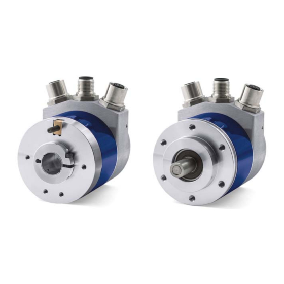
Datalogic AMT58*-PN Series Instruction Manual (145 pages)
ProfiNET Absolute Encoders
Brand:
Datalogic
| Category:
Media Converter
| Size: 8 MB
Table of Contents
Table of Contents
3
1 Safety Summary
17
2 Identification
19
3 Mechanical Installation
20
Solid Shaft Encoders
20
Customary Installation
20
Installation Using Fixing Clamps (Code LKM-386)
20
Installation Using a Flange (Code ST-58-FLNG)
21
Hollow Shaft Encoders
22
Amt58-H15
22
4 Electrical Connections
23
PWR Power Supply Connector (Fig.1)
23
Figure 1 - Connectors and Diagnostic Leds
23
P1 Port 1 and P2 Port 2 Connectors (Fig.1)
24
Ground Connection (Fig.1)
24
MAC Address and IP Address
24
Diagnostic Leds (Fig.1)
25
5 Getting Started
26
Configuring the Encoder with Siemens SIMATIC STEP 7
26
Mac Address
26
Encoder Installation under STEP 7 Environment
27
Description of the GSDML File
27
Installing the GSDML File
28
Figure 2 - Installing the GSDML File
28
Figure 3 - Selecting the GSDML File
29
Figure 4 - GSDML File Installation
29
Figure 5 - Scrolling through Profinet Families and Categories
30
Inserting the Module in the Profinet-IO System
31
Figure 6 - Inserting a Module in the Profinet-IO System
31
Figure 7 - Inserted Module
31
Figure 8 - Adding the Standard Telegram
32
Device Name and IP Address at Delivery
33
Setting the Device Name
33
Figure 9 - Assigning the Device Name
35
Figure 10 - Assigning the IP Address
36
Figure 11 - Downloading Data to the PLC
37
Figure 12 - Assigning the Device Name
38
Figure 13 - Confirming the Device Name
39
Figure 14 - Edit Ethernet Node Dialog Box
40
Figure 15 - Edit Ethernet Node Confirmation
41
Figure 16 - Browsing the Network
41
Checking the Device Name
42
Figure 17 - Verifying Device Name
42
Figure 18 - Verifying Device Name
42
Setting the IP Address
43
Figure 19 - Setting the IP Address
43
Figure 20 - Browsing the Network
44
Figure 21 - Assigning IP Configuration
45
Figure 22 - Edit Ethernet Node Confirmation
45
Setting the Parameters: Parameter Access Point
46
Figure 23 - Browsing the Network
46
Figure 24 - Entering the Parameter Access Point Dialog Box
46
Figure 25 - Parameter Access Point Properties
47
Figure 26 - Downloading Data to the PLC
47
Resetting the Parameters to Default Factory Values
48
Figure 27 - Parameter Access Point Help Messages
48
Figure 28 - Restoring Default Values
49
Figure 29 - Reset to Factory Settings
50
Figure 30 - Reset First Confirmation Message
50
Figure 31 - Reset Second Confirmation Message
51
Figure 32 - Reset Executed Message
51
Figure 33 - Checking Data after Reset
52
6 Profinet Interface
53
A Brief Introduction to Profinet
53
Profinet Encoders from Datalogic Automation S.r.l
54
Overview of the Encoder Profiles
55
Application Class Definition
55
Application Class 3
55
Application Class 4
55
Encoder Object Model
55
Encoder Object Architecture
57
7 PROFINET IO Data Description
58
Telegrams
58
Standard Telegram 81
58
Standard Telegram 82
58
Standard Telegram 83
59
Standard Telegram 84
59
8 Cyclic Data Exchange–Standard Signals
60
G1_Xist1
61
G1_Xist2
62
G1_Xist3
63
Zsw2_Enc
64
G1_Stw
65
Request Absolute Value Cyclically
67
Acknowledging a Sensor Error
68
9 Acyclic Data Exchange
69
Index 0Xaff0: Identification & Maintenance (I&M) Functions
70
P975 – Encoder Object Identification
71
P979 – Sensor Format
72
Index 0Xb02E : Supported Encoder Specific Parameters
73
Index 0Xbf00 : User Parameter Data
75
Class 4 Functionality
76
Scaling Function Control
77
Compatibility Mode
78
Measuring Units / Revolution
79
Maximum Master Sign-Of-Life Failures
80
Velocity Measuring Units
81
Red Zone
82
10 Diagnostics and Alarms
84
Acyclic Diagnosis Parameter
85
Use of the Channelerrortype
86
11 Real Time Class Communication
87
Figure 34 - Setting the Not Synchronized Role of the IO Controller
88
Figure 35 - Setting the Not Synchronized Role of the IO Device
89
Real-Time Class 3 (IRT_TOP) (RT3)
89
Figure 36 - Setting the Sync Master Role of the IO Controller
90
Setting an Isochronous Communication
90
Figure 37 - Setting the Sync Slave Role of the IO Device
91
Figure 38 - CPU Property Sheet
92
Figure 39 - PIP of OB61
93
Figure 40 - OB61: Assigning IO Device in Isochronous Mode
94
Figure 41 - Standard Telegram as Isochronous Submodule
95
Figure 42 - Setting PIP for Standard Telegram Ios
96
Figure 43- Configuring the IO Controller Topology
97
Figure 44 - Configuring the IO Device Topology
98
Figure 45 - Checking the Profinet IO Isochronous Mode
99
Figure 46 - Isochronous Mode Dialog Box
100
Figure 47 - OB61
101
Figure 48 - Process Image Partition
102
PIP (Process Image Partition)
102
Sfc126 "Sync_Pi
103
Domain Management
104
Figure 49 - Assigning the IO Device to a Sync Domain
105
Figure 50 - Domain Management Dialog Box
106
Figure 51 - Sync Domain Details Dialog Box
107
Figure 52 - Entering the Topology Editor
108
Figure 53 - Topology Editor: Table View
109
Figure 54 - Topology Editor: Offline/Online Comparison
110
Figure 55 - Topology Editor: Graphic View
111
Figure 56 - Message Monitoring
112
Figure 57 - Link Layer Discovery Protocol (LLDP)
113
12 Encoder Replacement Using LLDP
113
Figure 58 - Base Mode Parameter Request and Response
114
Read & Write Records in Acyclic Communication
114
13 Read & Write Records in Acyclic Communication
115
Figure 59 - SFB52
115
Example: Reading and Writing a Parameter (Preset Value)
115
Figure 60 - SFB53
115
Data Block 1 (DB1)
116
Figure 61 - DB1
116
Figure 62 - DB2
116
Data Block 3 (DB3)
117
Figure 63 - DB3
117
Figure 64 - DB4
117
Figure 65 - OB1
118
Figure 66 - FC1
118
Organization Block 1 (OB1)
118
Figure 67 - FC1
119
Figure 68 - FC2
119
Function 2 (FC2)
119
Figure 69 - Acyclic Request of Preset Value
120
Figure 70 - Monitoring a Variable
121
Figure 71 - Encoder State Machine
122
14 Encoder State Machine
123
Normal Operation Diagram
123
Preset Diagram
124
Parking Sensor Diagram
125
Error Diagram
126
Acknowledgment of Not Acknowledgeable Sensor Error
127
Figure 72 - Opening the Web Server
128
15 Integrated Web Server
128
Figure 73 - Web Server Index Page
129
Figure 74 - Encoder Information Page
129
Figure 75 - Firmware Upgrade Page
130
Figure 76 - Status & Alarms Page
130
Figure 77 - Encoder Parameters Page
131
Figure 78 - Encoder Specific Profile Parameters Page
131
Figure 79 - Encoder Specific Profile Parameters
132
Figure 80 - Encoder Specific Profile Parameters
132
Figure 81 - Identification & Maintenance Page
133
Figure 82 - Change the Preset Value Page
134
Figure 83 - Reserved Area Page
134
Firmware Upgrade
135
Figure 84 - Opening the Web Server
136
Figure 85 - Web Server Index Page
136
Figure 86 - Confirming the Access to the Firmware Upgrade Page
137
Figure 87 - Firmware Upgrade Page
137
Figure 88 - Web Server Stopped
138
Figure 89 - Firmware Upgrade Executable File
138
Figure 90 - Starting the Firmware Upgrade Operation
139
Figure 91 - Firmware Upgrade Operation Process
140
Figure 92 - Opening the Web Server
141
Setting the Preset Value
141
Figure 93 - Web Server Index Page
142
Figure 94 - Confirming the Access to the Preset Page
142
Figure 95 - Changing the Preset Value
143
Figure 96 - Preset Value Stored Properly
143
16 Default Parameters List
144
Advertisement
Advertisement
Related Products
Datalogic AMT58 Series
Datalogic AMT58-PB Series
Datalogic Profibus AMT58 13x12 PB Series
Datalogic AMT58 16x14 CB Series
Datalogic AMT58-H15 13x12 CB
Datalogic AMT58-H15 16x14 CB
Datalogic AccuLazr AL5010
Datalogic A30
datalogic AV7000
Datalogic AV500
Datalogic Categories
Barcode Reader
Scanner
Accessories
PDA
Handhelds
More Datalogic Manuals
Login
Sign In
OR
Sign in with Facebook
Sign in with Google
Upload manual
Upload from disk
Upload from URL