Sign In
Upload
Manuals
Brands
Datalogic Manuals
Measuring Instruments
Arex 400
Datalogic Arex 400 Manuals
Manuals and User Guides for Datalogic Arex 400. We have
2
Datalogic Arex 400 manuals available for free PDF download: User Manual
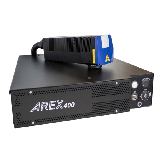
Datalogic Arex 400 User Manual (148 pages)
InfraRed Fiber Laser Marker
Brand:
Datalogic
| Category:
Measuring Instruments
| Size: 21 MB
Table of Contents
Table of Contents
3
Preface
7
About this Manual
7
Manual Conventions
7
Technical Support
8
Support through the Website
8
Reseller Technical Support
8
Introduction
9
General
9
Model Description
10
PRO Version
10
BASIC Version
10
CE Compliance
11
FCC Compliance
11
EAC Compliance
11
UL Compliance
12
Laser Standards
13
Overview
14
Laser Source
14
Galvanometric Scan Head
14
Operation of a Laser Marker with Galvanometric Scanning
14
Marking Software
15
Important Warnings
15
Installation
16
Unpacking
16
Contents of the Packaging
18
On Moisture Condensation
19
Note on Moisture Condensation
19
If Moisture Condensation Occurs
19
How to Avoid Moisture Condensation
19
Fixing and Positioning
20
Control Rack Installation
21
Horizontal Installation
21
Vertical Installation
23
Control Rack Mounting Screws Length
24
Scan Head Installation
25
Scan Head Mounting Screws Length
28
Installation Environment
29
Control Rack
29
Scan Head
30
Fume / Dust Extractor
31
Technical Specifications
32
Technical Characteristics
32
Product Description
34
Control Rack
34
Scan Head
35
Marking Area Specification
36
F-Theta Scan Lens for Arex™ 110-XXX and 120-XXX
37
F-Theta Scan Lens for Arex™ A20-X6X
37
F-Theta Scan Lens for Arex™ 130-X6X and 150-X6X
38
Green Spot
39
Connectors Specifications
40
Safety Circuit
40
Control Rack Back Panel Connector
40
Muting Device
42
Command Box (Laser Control)
43
Control Rack Back Panel Connector
43
Muting Device
44
Axes (I/O Control)
45
Control Rack Back Panel Connector
45
Encoder
46
Control Rack Back Panel Connector
46
Photocell
46
Device Port 1
47
Control Rack Back Panel Connector
47
Device Port 2
47
Rs232 (Com3)
48
Control Rack Back Panel Connector
48
Ext Focus
48
Scan Head Connector
48
Input/Output Specifications
49
Digital Input
49
Digital Output
49
Laser Marker States
50
Normal Operation States
50
Error States
51
Warning State
51
Control the Laser Marker States
52
Key Selector Mode
52
Command Box Mode
52
Timing Diagrams
53
Turning on Sequence
53
Marking Control Signals Behavior
53
Sw_Ready Output Signal (Ready to Mark Mode)
54
Good\Bad Output Signal
54
System_Alarm Output Signal
54
MARVIS™ I/O Signals Behavior
55
Safety Functions Behavior
55
Interlock Behavior
55
Laser_Stop Behavior
55
Green Spot Behavior
56
System Ready to Mark Mode
56
Marking Confirmation Mode
56
MARVIS Verification Mode
56
Axes I/O Signals Behavior
57
Lighter™ Suite Marking Software
57
Set up
60
Connections
60
Connecting Command Box Connector
60
Connecting Safety Circuit Connector
61
Connecting Power Supply Cable
62
Connecting the Earth Ground
62
Local Mode Control Connections
63
Remote Mode Control Connection
65
F-Theta Scan Lens Protection Cap Removal
66
Use and Operation
67
First Time Boot
68
Turning on Sequence
69
Sequence Using Key Selector
69
Sequence Using Command Box
72
Customize the Laser Marker Software
74
Change O.S. Language and Keyboard Layout
74
Change the LAN Configuration and IP Address
78
Change the Video Setting
81
Remote Desktop Connection
83
Accessories
84
Control Box
84
Remote Start Foot Switch
85
I/O Interface
85
DB25-To-Free Leads Cable
86
MARVIS™ Add-On
86
MARVIS™ Mounting Bracket
87
MARVIS™ LED Ring Light ID 50Mm - White
87
Micrometric Distance Sensor Kit
87
M39 F-Theta Protective Cap
88
Starter Kit for Marking on the Fly (MOF)
89
Rack Handles
90
Fume Extractor
90
Technical Support
91
Seals
91
Maintenance
92
F-Theta Scan Lens Cleaning Procedure
92
Air Filter Cleaning Procedure
93
Troubleshooting
94
Service Interface
94
List of Warning and Error States
96
List of Problems Related to Laser Marker States
97
List of most Common Problems
97
Remote Assistance
100
Labels
101
Positioning of External Labels
102
Positioning of Labels on the Control Rack
102
Positioning of Labels on the Scan Head
103
Safety Labels in Local Languages
103
Understanding Slo: Safe Laser off Safety Considerations According to en Iso 13849-1:2008
104
Machine Safety
104
Risk Assessment
104
Performance Level (PL)
106
Datalogic Laser Markers
106
SLO Connection Diagram
107
Safety Functions of Arex™ 400
108
Arex™ XXX-X5X
108
Arex™ XXX-X6X
108
Example 1
109
Example 2
110
Example 3
111
Laser Safety
112
Laser Radiation
114
Absorption of Laser Radiation
115
Classification and Danger Level
116
Degree of Risk with Radiation Viewing Conditions
116
Direct Viewing of the Laser Beam
116
Viewing of a Laser Reflected Beam
117
Viewing of Direct Laser Beam from a Fiber Output
117
Viewing of Scattered Laser Beam
117
Determination and O.D. of Protection Goggles
118
Accidental Vision of the Reflected Laser Radiation
119
Filter Scale Index of the Protection Goggles
119
Eyes and Skin Risks
119
General Safety Regulations
119
Other Risks
120
Using Marking Software
121
How to Create and Edit Graphics Layout
121
How to Test and Mark Layout
123
How to Use Command Box Signals to Mark Layout
125
Mopa Fiber Laser
127
Laser Marker Operations
127
Pulse Profile
129
Lighter™ Pulse Profile Configuration
131
Creating a Document with Multiple Objects Using a Single Pulse Profile
131
Creating a Document with Multiple Objects Using Different Pulse Profiles
132
Marking Software Upgrade
134
How to Update the Marking Software
134
Recover the Laser Marker
140
Overview
140
How to Recover the Laser Marker
140
Recover the System
140
Initialize the Hardware
143
Customize the Marking Software
144
Mechanical Drawings
145
Control Rack
146
Scan Head
147
Advertisement
Datalogic Arex 400 User Manual (145 pages)
Laser Marker
Brand:
Datalogic
| Category:
Measuring Instruments
| Size: 11 MB
Table of Contents
Table of Contents
3
Preface
7
General
7
Model Description
8
PRO Version
8
BASIC Version
8
CE Compliance
9
FCC Compliance
9
EAC Compliance
9
Laser Standards
10
Overview
11
Laser Source
11
Galvanometric Scan Head
11
Operation of a Laser Marker with Galvanometric Scanning
11
Marking Software
11
Important Warnings
12
Installation
13
Unpacking
14
Contents of the Packaging
16
On Moisture Condensation
17
Note on Moisture Condensation
17
If Moisture Condensation Occurs
17
How to Avoid Moisture Condensation
17
Fixing and Positioning
18
Control Rack Installation
19
Horizontal Installation
19
Vertical Installation
21
Control Rack Mounting Screws Length
22
Scan Head Installation
23
Scan Head Mounting Screws Length
26
Installation Environment
27
Control Rack
27
Scan Head
28
Fume / Dust Extractor
29
Technical Specifications
30
Technical Characteristics
31
Product Description
32
Control Rack
32
Scan Head
33
Marking Area Specification
34
F-Theta Scan Lens for Arex™ 110-XXX, 120-XXX and A20-X6X
34
F-Theta Scan Lens for Arex™ 130-X6X and 150-X6X
35
Green Spot
36
Connectors Specifications
37
Safety Circuit
37
Control Rack Back Panel Connector
37
Muting Device
39
Command Box (Laser Control)
40
Control Rack Back Panel Connector
40
Muting Device
41
Axes (I/O Control)
42
Control Rack Back Panel Connector
42
Encoder
43
Control Rack Back Panel Connector
43
Photocell
43
Device Port 1
44
Control Rack Back Panel Connector
44
Device Port 2
44
Rs232 (Com2)
45
Control Rack Back Panel Connector
45
Ext Focus
45
Scan Head Connector
45
Input/Output Specifications
46
Digital Input
46
Digital Output
46
Laser Marker States
47
Normal Operation States
47
Error States
47
Warning State
47
Control the Laser Marker States
48
Key Selector Mode
48
Command Box Mode
48
Timing Diagrams
49
Turning on Sequence
49
Marking Control Signals Behavior
49
Sw_Ready Output Signal (Ready to Mark Mode)
50
Good\Bad Output Signal
50
System_Alarm Output Signal
50
MARVIS™ I/O Signals Behavior
51
Safety Functions Behavior
51
Interlock Behavior
51
Laser_Stop Behavior
51
Green Spot Behavior
52
System Ready to Mark Mode
52
Marking Confirmation Mode
52
MARVIS Verification Mode
52
Axes I/O Signals Beavior
53
Lighter™ Suite Marking Software
54
Installation and Set up
56
Connections
57
Connecting Command Box Connector
57
Connecting Safety Circuit Connector
58
Connecting Power Supply Cable
59
Connecting the Earth Ground
59
Local Mode Control Connections
60
Remote Mode Control Connection
61
F-Theta Scan Lens Protection Cap Removal
61
Use and Operation
62
First Time Boot
63
Turning on Sequence
64
Sequence Using Key Selector
64
Sequence Using Command Box
67
Customize the Laser Marker Software
68
Change O.S. Language and Keyboard Layout
69
Change the LAN Configuration and IP Address
72
Change the Video Setting
75
Remote Desktop Connection
77
Accessories
78
Control Box
79
Remote Start Foot Switch
79
I/O Interface
80
DB25-To-Free Leads Cable
80
MARVIS™ Add-On
81
MARVIS™ Mounting Bracket
81
MARVIS™ LED Ring Light ID 50Mm - White
81
Micrometric Distance Sensor Kit
82
M39 F-Theta Protective Cap
82
Starter Kit for Marking on the Fly (MOF)
83
Rack Handles
83
LAS160 Fume Extractor
83
Technical Support
84
Seals
85
Maintenance
86
F-Theta Scan Lens Cleaning Procedure
86
Air Filter Cleaning Procedure
87
Troubleshooting
88
Service Interface
88
List of Warning and Error States
89
List of Problems Related to Laser Marker States
89
List of most Common Problems
90
Remote Assistance
91
Product Support and Customer Service
91
Labels
92
Labels
93
Positioning of External Labels
94
Positioning of Labels on the Control Rack
94
Positioning of Labels on the Scan Head
94
Understanding Slo: Safe Laser off
95
Machine Safety
96
Risk Assessment
97
Performance Level (PL)
98
Datalogic Laser Markers
98
SLO Connection Diagram
99
Safety Functions of Arex™ 400
100
Arex™ XXX-X5X
100
Arex™ XXX-X6X
100
Example 1
101
Example 2
102
Example 3
103
Laser Safety
104
Laser Radiation
106
Absorption of Laser Radiation
107
Classification and Danger Level
108
Degree of Risk with Radiation Viewing Conditions
108
Direct Viewing of the Laser Beam
108
Viewing of a Laser Reflected Beam
109
Viewing of Direct Laser Beam from a Fiber Output
109
Viewing of Scattered Laser Beam
109
N.O.H.D. Determination and O.D. of Protection Goggles
110
Accidental Vision of the Reflected Laser Radiation
111
Filter Scale Index of the Protection Goggles
111
Eyes and Skin Risks
111
General Safety Regulations
111
Other Risks
112
Using Marking Software
113
How to Create and Edit Graphics Layout
114
How to Test and Mark Layout
117
How to Use Command Box Signals to Mark Layout
119
Mopa Fiber Laser
121
Laser Marker Operations
122
Pulse Profile
124
Lighter™ Pulse Profile Configuration
126
Creating a Document with Multiple Objects Using a Single Pulse Profile
126
Creating a Document with Multiple Objects Using Different Pulse Profiles
127
Marking Software Upgrade
129
How to Update the Marking Software
130
Recover the Laser Marker
135
Overview
136
How to Recover the Laser Marker
136
Recover the System
136
Initialize the Hardware
139
Customize the Marking Software
140
Mechanical Drawings
141
Control Rack
142
Scan Head
143
Advertisement
Related Products
Datalogic AREX 401
Datalogic Arex 420
Datalogic A20
Datalogic AMT58 Series
Datalogic AMT58-PB Series
Datalogic Profibus AMT58 13x12 PB Series
Datalogic AMT58 16x14 CB Series
Datalogic AMT58-H15 13x12 CB
Datalogic Joya Touch A6 HC
Datalogic AI7000
Datalogic Categories
Barcode Reader
Scanner
Accessories
PDA
Handhelds
More Datalogic Manuals
Login
Sign In
OR
Sign in with Facebook
Sign in with Google
Upload manual
Upload from disk
Upload from URL