Sign In
Upload
Manuals
Brands
adept technology Manuals
Robotics
Adept Cobra i600
adept technology Adept Cobra i600 Manuals
Manuals and User Guides for adept technology Adept Cobra i600. We have
2
adept technology Adept Cobra i600 manuals available for free PDF download: User Manual
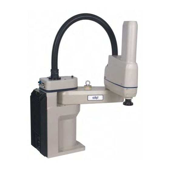
adept technology Adept Cobra i600 User Manual (150 pages)
Robot
Brand:
adept technology
| Category:
Robotics
| Size: 3.83 MB
Table of Contents
Table of Contents
5
Introduction
15
Product Description
15
Adept Cobra I600/I800 Robots
15
Figure 1-1. Adept Cobra I800 Robot
15
Adept Amps-In-Base (AIB)
16
Figure 1-2. Robot Joint Motions
16
Figure 1-3. Adept AIB
16
Installation Overview
17
Manufacturer's Declaration
17
How Can I Get Help
18
Related Manuals
18
Adept Document Library
18
Safety
19
Dangers, Warnings, Cautions, and Notes
19
Warning Labels on the Robot
20
Figure 2-1. Electrical and Thermal Warning Labels on AIB Chassis
20
Figure 2-2. Thermal Warning Label on Underside of Inner Link
20
Figure 2-3. Warning Label on Encoder Cables
21
Precautions and Required Safeguards
22
Safety Barriers
22
Front Panel Location
22
Impact and Trapping Points
23
Instructions for Emergency Movement Without Drive Power
23
Emergency Recovery Procedures
23
Additional Safety Information
24
Risk Assessment
25
Exposure
25
Severity of Injury
26
Avoidance
26
Slow-Speed Control Function and Testing
26
Control System Behavior Category
27
Intended Use of the Robots
28
Robot Modifications
29
Acceptable Modifications
29
Unacceptable Modifications
29
Transport
30
Safety Requirements for Additional Equipment
30
Sound Emissions
30
2.10 Thermal Hazard
31
2.11 Working Areas
31
Qualification of Personnel
31
2.13 Safety Equipment for Operators
32
2.14 Protection against Unauthorized Operation
32
2.15 Safety Aspects While Performing Maintenance
33
2.16 Risks Due to Incorrect Installation or Operation
33
2.17 What to Do in an Emergency Situation
33
Robot Installation
35
Transport and Storage
35
Figure 3-1. Cobra Robot on a Transportation Pallet
35
Unpacking and Inspecting the Adept Equipment
36
Before Unpacking
36
Upon Unpacking
36
Repacking for Relocation
36
Environmental and Facility Requirements
37
Mounting the Robot
37
Mounting Surface
37
Robot Mounting Procedure
38
Figure 3-2. Mounting Hole Pattern for Robot
38
Connectors on the Robot Interface Panel
40
Figure 3-3. Robot Interface Panel
40
System Installation
41
Cable and Parts List
41
System Cable Diagram
42
Figure 4-1. Icobra System Cable Diagram
42
Cable Connections to the Robot
43
Installing AIB XPANEL Cable
43
Installing Peripherals and Options
43
Connecting User-Supplied PC to Robot
43
PC Requirements
44
Installing Serial Cable
44
Installing Adept ACE Software
44
Figure 4-2. Adept ACE CD-ROM Startup Menu
45
Figure 4-3. Setup Welcome Screen
45
Figure 4-4. Ready-To-Install Screen
45
Figure 4-5. Install Screen
46
Figure 4-6. Installation Completed
46
Connecting 24 VDC Power to Robot
47
Specifications for 24 VDC Power
47
24 VDC to Robot
48
Figure 4-7. User-Supplied 24 VDC Cable
49
Connecting 200-240 VAC Power to Robot
50
Specifications for AC Power
50
Figure 4-8. Typical AC Power Installation with Single-Phase Supply
51
Details for AC Mating Connector
52
Figure 4-9. Single-Phase Load Across L1 and L2 of a Three-Phase AC Supply
52
Procedure for Creating 200-240 VAC Cable
53
Installing AC Power Cable to Robot
53
Figure 4-10. AC Power Mating Connector
53
Grounding the Adept Robot System
54
Ground Point on Robot Base
54
Robot-Mounted Equipment Grounding
54
Installing User-Supplied Safety Equipment
54
Figure 4-11. Ground Point on Robot Base
54
Optional Equipment Installation
57
Installing End-Effectors
57
Removing and Installing the Tool Flange
57
Removing the Flange
57
Installing the Flange
58
User Connections on the Robot
58
User Air Lines
58
Figure 5-1. Tool Flange Removal Details
58
User Electrical Lines
59
Figure 5-2. User Connectors on Joint1
59
Figure 5-3. User Connectors on Joint 2
59
Internal User Connectors
60
Figure 5-4. Internal User Connectors - OP3/4, EOAPWR, ESTOP
60
Figure 5-5. SOLND Connector
60
SOLND Connector
61
OP3/4 Connector
61
EOAPWR Connector
62
Figure 5-6. OP3/4 and SOLND Circuits
62
Internal User Connector Output Specifications
63
ESTOP Connector
63
Figure 5-7. Internal E-Stop Connector Circuit
64
Figure 5-8. Selecting the Configuration Manager
64
Mounting Locations for External Equipment
65
Installing the Robot Solenoid Kit
65
Introduction
65
Tools Required
66
Procedure
66
Figure 5-9. Solenoid Mounting Bracket with Connector and Spare Air Line
67
Figure 5-10. Solenoid Placement Using Mounting Hardware
68
Figure 5-11. Removing the Cable Strap Plate
68
Figure 5-12. Connecting Spare Air Line to User Connector
69
Installing Adjustable Hardstops
70
Joint 1 Adjustable Hardstops
70
Figure 5-13. Joint 1 Adjustable Hardstops
70
Figure 5-14. Configuration Manager - Modifying Joint 1 Limits
71
Joint 2 Adjustable Hardstops
72
Figure 5-15. Configuration Manager - Apply Changes
72
Figure 5-16. Joint 2 Hardstop Kit
72
Figure 5-17. Joint 2 Adjustable Hardstop Locations
73
Figure 5-18. Fixed Hardstop Device for Joint 2
73
Figure 5-19. Screw Locations for Joint 2 Adjustable Hardstops
74
Figure 5-20. Configuration Manager - Modifying Joint 2 Limits
75
System Operation
77
Robot Status LED
77
Figure 6-1 Robot Status LED Indicator Location
77
Status Panel Fault Codes
78
Figure 6-2 Status Panel
78
Using the Brake Release Button
79
Brakes
79
Brake Release Button
79
Front Panel
80
Figure 6-3 Front Panel
80
Connecting Digital I/O to the System
81
Figure 6-4 Connecting Digital I/O to the System
82
Using Digital I/O on Robot XIO Connector
83
XIO Connector
83
XIO Input Signals
84
Figure 6-5 Typical User Wiring for XIO Input Signals
85
XIO Output Signals
86
XIO Breakout Cable
87
Figure 6-6 Typical User Wiring for XIO Output Signals
87
Figure 6-7 Optional XIO Breakout Cable
87
Connecting Customer-Supplied Safety and Power Control Equipment
89
Connecting Equipment to the System
89
Figure 6-8 Cobra I600/I800 E-Stop Circuit Connections
92
Emergency Stop Circuits
93
Figure 6-9 Front Panel Schematic
93
Remote Manual Mode
94
Remote High Power On/Off Control
94
High Power On/Off Lamp
95
Remote Front Panel or User-Supplied Replacement
95
Turning on the System
96
Verifying Installation
96
Turning on Power and Starting Adept ACE
97
Figure 6-10 Adept ACE Startup Menu
97
Enabling High Power
98
Figure 6-11 Connecting to the Icobra
98
Figure 6-12. Selecting the Diagnostics Wizard
99
Figure 6-13 Adept Diagnostics Wizard
99
Figure 6-14 Diagnostics Wizard Enable Power Sequence
100
Figure 6-15 High Power Button on Front Panel
100
Figure 6-16 Diagnostics Wizard Complete
101
Figure 6-17 High Power and Launch Robot Jog Control Icons
101
Figure 6-18 Robot Jog Control Window
102
Verifying E-Stop Functions
103
Learning to Program the Adept Cobra I-Series Robot
103
Figure 6-19 Jog pendant Menu
103
Maintenance
105
Field-Replaceable Parts
105
Periodic Maintenance Schedule
105
Checking Safety Systems
106
Checking Robot Mounting Bolt Torque
106
Checking Robot for Oil Around Harmonic Drive
107
Lubricating Joint 3 Ball Screw/Spline
107
Required Grease for the Robot
107
Lubrication Procedure
107
Figure 7-1. Lubrication of Joint 3 Quill
109
Replacing the AIB Chassis
110
Removing the AIB Chassis
110
Figure 7-2. Securing Screw on AIB Chassis
110
Figure 7-3. Opening and Removing AIB Chassis
111
Figure 7-4. Connectors on AIB Chassis
111
Installing a New AIB Chassis
112
Figure 7-5. Ground Screw on AIB Chassis
112
Figure 7-6. AIB Jumper
112
Figure 7-7. Installing AIB Chassis in Robot Base
113
Replacing Encoder Battery
114
Battery Replacement Time Periods
114
Battery Replacement Procedure
114
Figure 7-8. Location of Encoder Battery
115
Technical Specifications
117
Dimension Drawings
117
Figure 8-1. Adept Cobra I600/S600 Top and Side Dimensions
117
Figure 8-2. Adept Cobra I800/S800 Top and Side Dimensions
118
Figure 8-3. Dimensions of the Camera Bracket Mounting Pattern
119
Figure 8-4. Tool Flange Dimensions
120
Figure 8-5. External Tooling on Top of Robot Arm
121
Figure 8-6. External Tooling on Underside of Outer Link
122
Figure 8-7. Adept Cobra I600/S600 Robot Working Envelope
123
Figure 8-8. Adept Cobra I800/S800 Robot Working Envelope
124
Robot Specifications
125
Cleanroom Robots
127
Cobra I600/I800 Cleanroom Option
127
Introduction
127
Figure 9-1. Adept Cobra I600 Cleanroom Robot
127
Specifications
128
Connections
128
Requirements
128
Figure 9-2. Cleanroom Connections
128
Exclusions and Incompatibilities
129
Maintenance
129
Bellows Replacement
129
Lubrication
130
Figure 9-3. Cleanroom Bellows Replacement
130
10.1 Cobra I800 IP-65 Classification
131
10.2 Installing Cable Seal Assembly
131
Cable Seal Identification
131
Figure 10-1. Adept Cobra I800 Robot - IP-65 Version
131
Installation Procedure
132
Figure 10-2. Cable Seal Parts
132
Figure 10-3. Cable Seal Housing Installed
132
Figure 10-4. Installing Lower Flange
133
Figure 10-5. Lower Flange in Position
133
Figure 10-6. Upper Flange Installed
133
10.3 Robot Outer Link Cover Removal and Reinstallation
134
Cover Removal Procedure
134
Figure 10-7. Splash Guard Installed
134
Cover Reinstallation Procedure
135
Figure 10-8. Cover Removal Instructions
135
Figure 10-9. IP-65 Robot with Outer Link Cover Removed
135
10.4 Customer Requirements
137
Sealing the Tool Flange
137
Figure 10-10. Cobra IP-65 Tool Flange
137
Pressurizing the Robot
138
Figure 10-11. Compressed Air Fitting on Robot
138
10.5 User Connectors
139
User Electrical and Devicenet
139
Figure 10-12. User Connectors on Joint 1 Cover
139
Figure 10-13. IP-65 Internal Connectors with Outer Link Cover Removed
139
User Air Lines
140
Robot Solenoid Option
140
10.6 Maintenance
141
IP-65 Bellows Replacement
141
Figure 10-14. Bellows Replacement
141
10.7 Dimension Drawing for Cable Seal Assembly
142
Figure 10-15. Bellows Clamp Alignment
142
Figure 10-16. Cable Seal Assembly Dimensions
142
Advertisement
adept technology Adept Cobra i600 User Manual (110 pages)
Brand:
adept technology
| Category:
Robotics
| Size: 2.48 MB
Table of Contents
Table of Contents
5
1 Introduction
11
Product Description
11
Adept Cobra I600/I800™ Robots
11
Figure 1-1. Adept Cobra I800 Robot
11
Adept Amps-In-Base (AIB™)
12
Figure 1-2. Robot Joint Motions
12
Figure 1-3. Adept AIB
12
Dangers, Warnings, Cautions, and Notes
13
Safety Precautions
13
What to Do in an Emergency Situation
14
Additional Safety Information
14
Manufacturer's Declaration of Compliance (MDOC)
14
Adept Robot Safety Guide
14
Intended Use of the Robots
14
Installation Overview
15
Manufacturer's Declaration
15
How Can I Get Help
16
Related Manuals
16
Adept Document Library
16
2 Robot Installation
17
Transport and Storage
17
Figure 2-1. Cobra Robot on a Transportation Pallet
17
Unpacking and Inspecting the Adept Equipment
18
Before Unpacking
18
Upon Unpacking
18
Repacking for Relocation
18
Environmental and Facility Requirements
19
Mounting the Robot
19
Mounting Surface
19
Robot Mounting Procedure
20
Figure 2-2. Mounting Hole Pattern for Robot
20
Connectors on the Robot Interface Panel
22
Figure 2-3. Robot Interface Panel
22
3 System Installation
23
Cable and Parts List
23
System Cable Diagram
24
Figure 3-1. Icobra System Cable Diagram
24
Cable Connections to the Robot
25
Installing AIB XPANEL Cable
25
Installing Peripherals and Options
25
Connecting User-Supplied PC to Robot
25
PC Requirements
26
Installing Serial Cable
26
Installing Adept ACE Software
26
Figure 3-2. Adept ACE CD-ROM Startup Menu
27
Figure 3-3. Setup Welcome Screen
27
Figure 3-4. Ready-To-Install Screen
27
Figure 3-5. Install Screen
28
Figure 3-6. Installation Completed
28
Connecting 24 VDC Power to Robot
29
Specifications for 24 VDC Power
29
Connecting 24 VDC
30
Connecting 200-240 VAC Power to Robot
31
Specifications for AC Power
31
Figure 3-7. User-Supplied 24 VDC Cable
31
Details for AC Mating Connector
33
Figure 3-8. Typical AC Power Installation with Single-Phase Supply
33
Figure 3-9. Single-Phase Load Across L1 and L2 of a Three-Phase AC Supply
33
Procedure for Creating 200-240 VAC Cable
34
Installing AC Power Cable to Robot
34
Grounding the Adept Robot System
34
Figure 3-10. AC Power Mating Connector
34
Ground Point on Robot Base
35
Robot-Mounted Equipment Grounding
35
Installing User-Supplied Safety Equipment
35
Figure 3-11. Ground Point on Robot Base
35
4 System Operation
37
Robot Status LED
37
Status Panel Fault Codes
37
Figure 4-1 Robot Status LED Indicator Location
37
Figure 4-2 Status Panel
38
Using the Brake Release Button
39
Brakes
39
Brake Release Button
39
Front Panel
40
Figure 4-3 Front Panel
40
Connecting Digital I/O to the System
41
Figure 4-4 Connecting Digital I/O to the System
42
Using Digital I/O on Robot XIO Connector
43
XIO Connector
43
XIO Input Signals
44
Figure 4-5 Typical User Wiring for XIO Input Signals
45
XIO Output Signals
46
XIO Breakout Cable
47
Figure 4-6 Typical User Wiring for XIO Output Signals
47
Figure 4-7 Optional XIO Breakout Cable
47
Connecting Customer-Supplied Safety and Power Control Equipment
49
Connecting Equipment to the System
49
Figure 4-8 Cobra I600/I800 E-Stop Circuit Connections
52
Emergency Stop Circuits
53
Figure 4-9 Front Panel Schematic
53
Remote Manual Mode
54
Remote High Power On/Off Control
54
High Power On/Off Lamp
55
Remote Front Panel or User-Supplied Replacement
55
Turning on the System
55
Verifying Installation
55
Turning on Power and Starting Adept ACE
56
Enabling High Power
57
Figure 4-10 Adept ACE Startup Menu
57
Figure 4-11 Connecting to the Icobra
57
Figure 4-12 High Power and Launch Robot Jog Control Icons
58
Figure 4-13 Robot Jog Control Window
59
Verifying E-Stop Functions
60
Learning to Program the Adept Cobra I-Series Robot
60
Figure 4-14 Jog Pendant Menu
60
5 Maintenance
61
Field-Replaceable Parts
61
Periodic Maintenance Schedule
61
Checking Safety Systems
62
Checking Robot Mounting Bolt Torque
62
Checking Robot for Oil Around Harmonic Drive
62
Lubricating Joint 3 Ball Screw/Spline
63
Required Grease for the Robot
63
Lubrication Procedure
63
Figure 5-1. Lubrication of Joint 3 Quill
64
Replacing the AIB Chassis
65
Removing the AIB Chassis
65
Figure 5-2. Securing Screw on AIB Chassis
65
Figure 5-3. Opening and Removing AIB Chassis
66
Figure 5-4. Connectors on AIB Chassis
66
Installing a New AIB Chassis
67
Figure 5-5. Ground Screw on AIB Chassis
67
Figure 5-6. Installing AIB Chassis in Robot Base
68
Replacing Encoder Battery
69
Battery Replacement Time Periods
69
Battery Replacement Procedure
69
Figure 5-7. Location of Encoder Battery Pack
70
6 Optional Equipment Installation
71
Installing End-Effectors
71
Removing and Installing the Tool Flange
71
Removing the Flange
71
Installing the Flange
72
User Connections on the Robot
72
User Air Lines
72
Figure 6-1. Tool Flange Removal Details
72
User Electrical Lines
73
Figure 6-2. User Connectors on Joint 1
73
Figure 6-3. User Connectors on Joint 2
73
Internal User Connectors
74
Figure 6-4. Internal User Connectors - OP3/4, EOAPWR, ESTOP
74
Figure 6-5. SOLND Connector
74
OP3/4 Connector
75
SOLND Connector
75
EOAPWR Connector
76
Figure 6-6. OP3/4 and SOLND Circuits
76
ESTOP Connector
77
Internal User Connector Output Specifications
77
Figure 6-7. Internal E-Stop Connector Circuit
78
Figure 6-8. Selecting the Configuration Manager
78
Mounting Locations for External Equipment
79
Installing the Robot Solenoid Kit
79
Introduction
79
Tools Required
80
Procedure
80
Figure 6-9. Solenoid Mounting Bracket with Connector and Spare Air Line
81
Figure 6-10. Solenoid Placement Using Mounting Hardware
82
Figure 6-11. Removing the Cable Strap Plate
82
Figure 6-12. Connecting Spare Air Line to User Connector
83
Installing Adjustable Hardstops
84
Joint 1 Adjustable Hardstops
84
Figure 6-13. Joint 1 Adjustable Hardstops
84
Figure 6-14. Configuration Manager - Modifying Joint 1 Limits
85
Joint 2 Adjustable Hardstops
86
Figure 6-15. Configuration Manager - Apply Changes
86
Figure 6-16. Joint 2 Hardstop Kit
86
Figure 6-17. Joint 2 Adjustable Hardstop Locations
87
Figure 6-18. Fixed Hardstop Device for Joint 2
87
Figure 6-19. Screw Locations for Joint 2 Adjustable Hardstops
88
Figure 6-20. Configuration Manager - Modifying Joint 2 Limits
89
7 Technical Specifications
91
Dimension Drawings
91
Figure 7-1. Adept Cobra I600/S600 Top and Side Dimensions
91
Figure 7-2. Adept Cobra I800/S800 Top and Side Dimensions
92
Figure 7-3. Dimensions of the Camera Bracket Mounting Pattern
93
Figure 7-4. Tool Flange Dimensions
94
Figure 7-5. External Tooling on Top of Robot Arm
95
Figure 7-6. External Tooling on Underside of Outer Link
96
Figure 7-7. Adept Cobra I600/S600 Robot Working Envelope
97
Figure 7-8. Adept Cobra I800/S800 Robot Working Envelope
98
Robot Specifications
99
8 Cleanroom Robots
101
Cobra I600/I800 Cleanroom Option
101
Introduction
101
Figure 8-1. Adept Cobra I600 Cleanroom Robot
101
Specifications
102
Connections
102
Requirements
102
Figure 8-2. Cleanroom Connections
102
Exclusions and Incompatibilities
103
Maintenance
103
Bellows Replacement
103
Lubrication
104
Figure 8-3. Cleanroom Bellows Replacement
104
Advertisement
Related Products
adept technology Adept Cobra i800
adept technology IO Blox
adept technology 550
adept technology 550A
adept technology 556
adept technology 557
adept technology AdeptThree
adept technology AdeptViper s650
adept technology AdeptViper s850
adept technology Cobra Dual
adept technology Categories
Robotics
Controller
Control Unit
Network Router
Thermostat
More adept technology Manuals
Login
Sign In
OR
Sign in with Facebook
Sign in with Google
Upload manual
Upload from disk
Upload from URL