Table of Contents
Advertisement
Quick Links
Advertisement
Table of Contents

Subscribe to Our Youtube Channel
Related Manuals for adept technology Adept Cobra i600


Summary of Contents for adept technology Adept Cobra i600
- Page 1 Adept Cobra i600/i800 Robot User’s Guide...
- Page 3 Adept Cobra i600/i800 Robot User’s Guide P/N: 03589-000, Rev G December, 2011 5960 Inglewood Drive • Pleasanton, CA 94588 • USA • Phone 925.245.3400 • Fax 925.960.0452 Otto-Hahn-Strasse 23 • 44227 Dortmund • Germany • Phone +49.231.75.89.40 • Fax +49.231.75.89.450 Block 5000 Ang Mo Kio Avenue 5 •...
- Page 4 The information contained herein is the property of Adept Technology, Inc., and shall not be reproduced in whole or in part without prior written approval of Adept Technology, Inc. The information herein is sub- ject to change without notice and should not be construed as a commitment by Adept Technology, Inc. This manual is periodically reviewed and revised.
-
Page 5: Table Of Contents
1.1 Product Description..........11 Adept Cobra i600/i800™ Robots ........11 Adept Amps-in-Base (AIB™) . - Page 6 High Power On/Off Lamp ........55 Remote Front Panel or User-Supplied Replacement ....55 Adept Cobra i600/i800 Robot User’s Guide, Rev G...
- Page 7 ESTOP Connector ..........77 Adept Cobra i600/i800 Robot User’s Guide, Rev G...
- Page 8 Lubrication ........... 104 Adept Cobra i600/i800 Robot User’s Guide, Rev G...
- Page 9 Tool Flange Removal Details ........72 Adept Cobra i600/i800 Robot User’s Guide, Rev G...
- Page 10 Figure 8-1. Adept Cobra i600 Cleanroom Robot ......101 Figure 8-2.
-
Page 11: Introduction
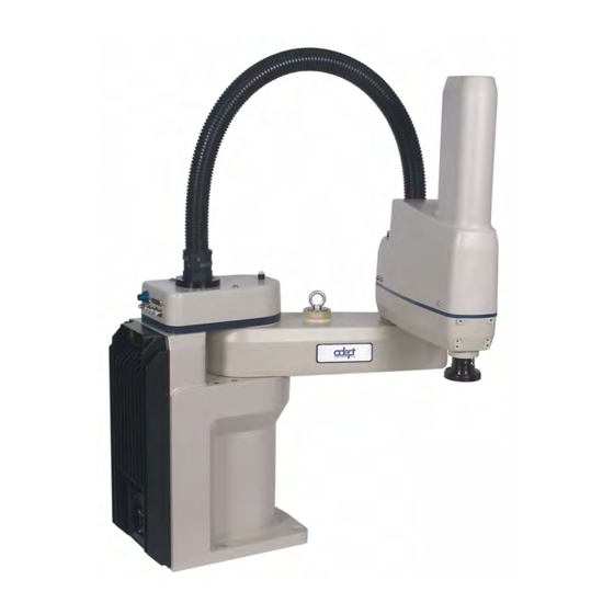
Introduction Product Description Adept Cobra i600/i800™ Robots The Adept Cobra i600 and i800 robots are four-axis SCARA robots (Selective Compliance Assembly Robot Arm). See the following figure. Joints 1, 2, and 4 are rotational; Joint 3 is translational. See Figure 1-2 for a description of the robot joint locations. -
Page 12: Adept Amps-In-Base (Aib™)
• Digital feed-forward design maximizes efficiency, torque, and velocity • Temperature sensors for all amplifiers and motors for maximum reliability and easy troubleshooting AIB on Adept Cobra i600 Robot Figure 1-3. Adept AIB Adept Cobra i600/i800 Robot User’s Guide, Rev G... -
Page 13: Dangers, Warnings, Cautions, And Notes
• All personnel who design the robot system must read this guide, read the Adept Robot Safety Guide, and must comply with all local and national safety regulations for the location in which the robot is installed. Adept Cobra i600/i800 Robot User’s Guide, Rev G... -
Page 14: What To Do In An Emergency Situation
See “Adept Document Library” on page 16. Intended Use of the Robots The Adept Cobra i600 and i800 robots are intended for use in parts assembly and material handling for payloads less than 5.5 kg (12.1 lb). Adept Cobra i600/i800 Robot User’s Guide, Rev G... -
Page 15: Installation Overview
1. Click on the appropriate .zip file. You are prompted to Open or Save the file. 2. Click Open to open the file and display the archive contents. 3. Double-click on a .pdf file to open it. Adept Cobra i600/i800 Robot User’s Guide, Rev G... -
Page 16: How Can I Get Help
To locate information on a specific topic, use the Document Library search engine on the ADL main page. To view a list of available product documentation, select the Active Documents option. Adept Cobra i600/i800 Robot User’s Guide, Rev G... -
Page 17: Robot Installation
The i600 robot weighs 41 kg (90 lb) and the i800 weighs 43 kg (95 lb) with no options installed. Eyebolt for lifting robot after robot has been unbolted from the transportation pallet. Place forklift or pallet-jack here. Figure 2-1. Cobra Robot on a Transportation Pallet Adept Cobra i600/i800 Robot User’s Guide, Rev G... -
Page 18: Unpacking And Inspecting The Adept Equipment
Before unbolting the robot from the shipping pallet, fold the outer arm against the Joint 2 hardstops to help centralize the center of gravity. The robot must always be shipped in an upright orientation. Adept Cobra i600/i800 Robot User’s Guide, Rev G... -
Page 19: Environmental And Facility Requirements
Mounting the Robot Mounting Surface The Adept Cobra i600 and i800 robots are designed to be mounted on a smooth, flat, level surface. The mounting structure must be rigid enough to prevent vibration and flexing during robot operation. Adept recommends a 25 mm (1 in.) thick steel plate mounted to a rigid steel tube frame. -
Page 20: Robot Mounting Procedure
Retain these bolts for possible later relocation of the equipment. 4. Lift the robot and position it directly over the mounting surface. 5. Slowly lower the robot while aligning the base and the tapped mounting holes in the mounting surface. Adept Cobra i600/i800 Robot User’s Guide, Rev G... - Page 21 Chapter 5 for periodic maintenance. Table 2-2. Mounting Bolt Torque Specifications Standard Size Specification Torque Metric M12 x P1.75 ISO Property Class 8.8 85 N·m 7/16-14 UNC SAE Grade 5 63 lbf·ft Adept Cobra i600/i800 Robot User’s Guide, Rev G...
-
Page 22: Connectors On The Robot Interface Panel
That section also contains details on how to access these I/O signals via MicroV+. (DB26, high density, female). The optional XIO Termination Block connects here. This device provides a termination block for I/O connections, plus status LEDs and switches to test I/O signals. Adept Cobra i600/i800 Robot User’s Guide, Rev G... -
Page 23: System Installation
User-supplied AC Power Cable - to supply AC User-supplied power to 24 VDC Power Supply RS-232 Null Modem Serial Cable, 04116-001 90565-000 Standard, iCobra 5 meter, for connecting user-supplied PC to robot Adept Cobra i600/i800 Robot User’s Guide, Rev G... -
Page 24: System Cable Diagram
(200-240 VAC 1 ) XPANEL RS-232 AC Power 200-240 VAC Cable 10 A User-Supplied PC single-phase running Adept ACE RS-232 Null Modem Cable for Robot to PC Connection Figure 3-1. iCobra System Cable Diagram Adept Cobra i600/i800 Robot User’s Guide, Rev G... -
Page 25: Cable Connections To The Robot
Connect the T1/T2 Adapter Cable to the matching connector on the T2. Connecting User-Supplied PC to Robot The Adept Cobra i600/i800 robots must be connected to a user-supplied PC for setup, control, and programming. The user loads the Adept ACE software onto the PC and connects it to the robot via an RS-232 serial cable. -
Page 26: Pc Requirements
3-2. If Autoplay is disabled, you will need to manually start the CD-ROM. NOTE: The online document that describes the installation process opens in the background when you select one of software installation steps below. Adept Cobra i600/i800 Robot User’s Guide, Rev G... -
Page 27: Figure 3-2. Adept Ace Cd-Rom Startup Menu
3. The Adept ACE Setup wizard opens - see Figure 3-4 Figure 3-5. Follow the instructions as you step through the installation process. Figure 3-3. Setup Welcome Screen Figure 3-4. Ready-to-Install Screen Adept Cobra i600/i800 Robot User’s Guide, Rev G... -
Page 28: Figure 3-5. Install Screen
5. After closing the Adept ACE Setup wizard, click Exit on the CD-ROM menu and proceed to the Start-up Procedure. NOTE: You will have to restart the PC after installing Adept ACE. Adept Cobra i600/i800 Robot User’s Guide, Rev G... -
Page 29: Connecting 24 Vdc Power To Robot
Table 3-2. Recommended 24 VDC Power Supplies Vendor Name Model Ratings XP Power JMP160PS24 24 VDC, 6.7 A, 160 W AstroDyne SP-150-24 24 VDC, 6.3 A, 150 W Mean Well SP-150-24 24 VDC, 6.3 A, 150 W Adept Cobra i600/i800 Robot User’s Guide, Rev G... -
Page 30: Connecting 24 Vdc
2. Plug the mating connector end of the 24 VDC cable into the 24 VDC connector on the interface panel on the back of the robot. The cable shield should be connected to the ground point on the interface panel. Adept Cobra i600/i800 Robot User’s Guide, Rev G... -
Page 31: Connecting 200-240 Vac Power To Robot
Voltage Voltage Breaker, Range User-Supplied 200 to 240 V 180 V 264 V 50/60 Hz/ 10 Amps 1-phase Specifications are established at nominal line voltage. Low line voltage can affect robot performance. Adept Cobra i600/i800 Robot User’s Guide, Rev G... - Page 32 3-phase system). This will cause high current pulses at relatively low voltage levels. The user shall take the necessary steps to prevent damage to the robot system (such as by interposing a transformer). See 1131-4 for additional information. Adept Cobra i600/i800 Robot User’s Guide, Rev G...
-
Page 33: Details For Ac Mating Connector
The supplied plug is internally labeled for the AC power connections (L, E, N). Table 3-6. AC Mating Connector Details AC Connector details AC in-line power plug, straight, female, screw terminal, 10 A, 250 VAC Qualtek P/N 709-00/00 Digi-Key P/N Q217-ND Adept P/N 02710-000 Adept Cobra i600/i800 Robot User’s Guide, Rev G... -
Page 34: Procedure For Creating 200-240 Vac Cable
3. Secure the AC connector with the locking latch. Grounding the Adept Robot System Proper grounding is good practice for safe and reliable robot operation. Follow these recommendations to properly ground your robot system. Adept Cobra i600/i800 Robot User’s Guide, Rev G... -
Page 35: Ground Point On Robot Base
Figure 3-11. Ground Point on Robot Base Robot-Mounted Equipment Grounding The following parts of an Adept Cobra i600/i800 robot are not grounded to protective earth: the Joint 3 quill and the tool flange. If hazardous voltages are present at any user-supplied robot-mounted equipment or tooling, you must install a ground connection from that equipment/tooling to the ground point on the robot base. -
Page 37: System Operation
All displayed faults will be cleared from the display, and reset to a no-fault condition, upon successfully enabling high power to the robot, or power cycling the 24 V supply to the robot. Adept Cobra i600/i800 Robot User’s Guide, Rev G... -
Page 38: Figure 4-2 Status Panel
For more information on status codes, go to the Adept Document Library on the Adept website, and in the Procedures, FAQs, and Troubleshooting section, look for the Adept Status Code Summary for Embedded Prodcts document. Adept Cobra i600/i800 Robot User’s Guide, Rev G... -
Page 39: Using The Brake Release Button
3 may drop to the bottom of its travel. To prevent possible damage to the equipment, make sure that Joint 3 is supported when releasing the brake and verify that the end-effector and other installed tooling is clear of all obstructions. Adept Cobra i600/i800 Robot User’s Guide, Rev G... -
Page 40: Front Panel
5. Emergency Stop Switch The E-Stop is a dual-channel, passive E-Stop that supports Category 3 CE safety requirements. Pressing this button turns off high power to the robot motors. Adept Cobra i600/i800 Robot User’s Guide, Rev G... -
Page 41: Connecting Digital I/O To The System
8 inputs, 8 outputs per device. Adept IO Blox User’s digital I/O capacity, You can combine up to four Guide connects to robot. IO Blox devices to increase capacity by 32 inputs and 32 outputs. Adept Cobra i600/i800 Robot User’s Guide, Rev G... -
Page 42: Figure 4-4 Connecting Digital I/O To The System
IO Blox 2 Inputs 1041 - 1048 Outputs 0041 - 0048 IO Blox 3 Inputs 1049 - 1056 Outputs 0049 - 0056 IO Blox 4 Inputs 1057 - 1064 Outputs 0057 - 0064 Adept Cobra i600/i800 Robot User’s Guide, Rev G... -
Page 43: Using Digital I/O On Robot Xio Connector
XIO 26-pin female Output 1 0001 connector on Robot Interface Panel Output 2 0002 Output 3 0003 Output 4 0004 Output 5 0005 Output 6 0006 Output 7 0007 Output 8 0008 Adept Cobra i600/i800 Robot User’s Guide, Rev G... -
Page 44: Xio Input Signals
5 µsec maximum Software scan rate/response time 16 ms scan cycle/32 ms max response time NOTE: The input current specifications are provided for reference. Voltage sources are typically used to drive the inputs. Adept Cobra i600/i800 Robot User’s Guide, Rev G... -
Page 45: Figure 4-5 Typical User Wiring For Xio Input Signals
This guarantees that the inputs will not be turned on by the leakage current from the outputs. This is useful in situations where the outputs are looped-back to the inputs for monitoring purposes. Adept Cobra i600/i800 Robot User’s Guide, Rev G... -
Page 46: Xio Output Signals
Output voltage at inductive load demag turnoff (I = 0.5 A, Load = 1 mH) 0.7 A I 2.5 A DC short circuit current limit 4 A Peak short circuit current ovpk Adept Cobra i600/i800 Robot User’s Guide, Rev G... -
Page 47: Xio Breakout Cable
04465-000, and the length is 5 M (16.4 ft). Table 4-8 on page 48 for the wire chart on the cable. NOTE: This cable is not compatible with the XIO Termination Block. Figure 4-7 Optional XIO Breakout Cable Adept Cobra i600/i800 Robot User’s Guide, Rev G... - Page 48 Output 4 Light Blue/Black Output 5 Light Green Output 6 Light Green/Black Output 7 White/Red Output 8 White/Blue Shell Shield Pin 1 Pin 9 Pin 10 Pin 18 Pin 19 Pin 26 Adept Cobra i600/i800 Robot User’s Guide, Rev G...
-
Page 49: Connecting Customer-Supplied Safety And Power Control Equipment
Not supported on Cobra i-series robot 9,22 Not supported on Cobra i-series robot 10,23 Not supported on Cobra i-series robot 11,12, No connection 13, 24, Pin 13 Pin 1 XUSR Pin 25 Pin 14 Adept Cobra i600/i800 Robot User’s Guide, Rev G... - Page 50 Figure 4-9 on page 53 for a schematic diagram of the Adept Front Panel. Users must exercise caution to avoid inadvertently connecting 24 V signals to these pins, because this will damage the electronics. Adept Cobra i600/i800 Robot User’s Guide, Rev G...
- Page 51 Serial GND/Logic GND T2 TXD: “Micro V to MCP TXD” T2 RXD: “Micro V to MCP RXD” No connection No connection Shield Shield GND 24 V (used by T2 Power Adapter) No connection Adept Cobra i600/i800 Robot User’s Guide, Rev G...
-
Page 52: Figure 4-8 Cobra I600/I800 E-Stop Circuit Connections
Force-Guided Relay bulb (XPANEL-13) Cyclic Check Control Circuit XFP-13 (XPANEL-21) XFP-14 (XPANEL-20) Single-Phase High Power to AC Input Amplifiers 200-240 VAC Force-Guided Force-Guided Relay Relay Figure 4-8 Cobra i600/i800 E-Stop Circuit Connections Adept Cobra i600/i800 Robot User’s Guide, Rev G... -
Page 53: Emergency Stop Circuits
E-Stop allowing access to the workspace of the robot in Manual mode only, not in Automatic mode. It is up to the customer to determine if teaching the robot in Manual Mode, by a skilled programmer (See "Qualification of Adept Cobra i600/i800 Robot User’s Guide, Rev G... -
Page 54: Remote Manual Mode
This method allows relocating the push-button switch to a more convenient location. Implementation of this method must conform to local and national standards. It is important that the remote High Power push button be located outside of the workspace of the robot. Adept Cobra i600/i800 Robot User’s Guide, Rev G... -
Page 55: High Power On/Off Lamp
Verifying that the system is correctly installed and that all safety equipment is working correctly is an important process. Before using the robot, make the following checks to ensure that the robot system has been properly installed. Adept Cobra i600/i800 Robot User’s Guide, Rev G... -
Page 56: Turning On Power And Starting Adept Ace
5. Turn on the user-supplied PC and start Adept ACE. Double-click the Adept ACE icon on your Windows desktop, or, from the Windows Start menu bar, select Start > Programs > Adept Technology > Adept ACE > Adept ACE. 6. Connect a serial cable from the PC to the robot. -
Page 57: Enabling High Power
After you have started Adept ACE and connected to the internal controller, enable high power to the robot motors. Using Adept ACE to Enable High Power 1. From the Adept ACE main menu, click the Enable High Power icon. See the following figure. Adept Cobra i600/i800 Robot User’s Guide, Rev G... -
Page 58: Figure 4-12 High Power And Launch Robot Jog Control Icons
3. Use the Robot Jog Control (see the following figure) to verify that each robot joint moves correctly in both directions. a. To access the Robot Jog Control, on the Adept ACE toolbar, click the Launch Robot Jog Control icon. See Figure 4-12. Adept Cobra i600/i800 Robot User’s Guide, Rev G... -
Page 59: Figure 4-13 Robot Jog Control Window
In the Mode section, click Joint. By default, Comp will be selected. c. Use the Robot Jog Control arrows to move Joint 1 a short distance in both directions. Repeat for Joints 2, 3, and 4. See the following figure. Adept Cobra i600/i800 Robot User’s Guide, Rev G... -
Page 60: Verifying E-Stop Functions
Learning to Program the Adept Cobra i-Series Robot To learn how to use and program the robot, go to the Adept ACE and MicroV+ online documentation in the Adept Document Library, to find information on basic operation and programming. Adept Cobra i600/i800 Robot User’s Guide, Rev G... -
Page 61: Maintenance
Use the times in as guidelines and modify the schedule as needed. Table 5-2 NOTE: Special maintenance for the Cleanroom version of iCobra robots is covered in Section 8.5 on page 103. Adept Cobra i600/i800 Robot User’s Guide, Rev G... -
Page 62: Checking Safety Systems
• The area around Joint 2 • Inside the base of the robot, by opening the AIB chassis and inspecting internally Contact Adept if you find any signs of oil in these areas. Adept Cobra i600/i800 Robot User’s Guide, Rev G... -
Page 63: Lubricating Joint 3 Ball Screw/Spline
Lithium Soap, Synthetic Hydrocarbon Adept part number: 85139-00002 CAUTION: Using improper lubrication products on the Adept Cobra i600 or i800 robot may cause damage to the robot. Lubrication Procedure 1. Turn off main power to the robot. 2. Remove the outer link cover by removing six screws located on the sides and top of the cover. -
Page 64: Figure 5-1. Lubrication Of Joint 3 Quill
Lube Point B Top View Looking Down NOTE: Apply grease to the three vertical grooves Vertical Groove and the spiral groove Lube Point C Section A-A Figure 5-1. Lubrication of Joint 3 Quill Adept Cobra i600/i800 Robot User’s Guide, Rev G... -
Page 65: Replacing The Aib Chassis
NOTE: The screw does not need to be completely removed in order to remove the chassis, as this screw is captured on the chassis heat sink. Securing Screw on AIB Figure 5-2. Securing Screw on AIB Chassis Adept Cobra i600/i800 Robot User’s Guide, Rev G... -
Page 66: Figure 5-3. Opening And Removing Aib Chassis
12. Carefully disconnect the J27 cable from the J27 connector on the PMAI, by disengaging the securing latches. 13. Carefully disconnect the J28 cable from the J28 connector on the PMAI, by disengaging the securing latches. Adept Cobra i600/i800 Robot User’s Guide, Rev G... -
Page 67: Installing A New Aib Chassis
7. Carefully connect the J1 cable to the J1 connector on the PMAI, and engage the securing latches. 8. Carefully connect the white amplifier cable to the amplifier connector located on the chassis bracket. Adept Cobra i600/i800 Robot User’s Guide, Rev G... -
Page 68: Figure 5-6. Installing Aib Chassis In Robot Base
17. Install MicroV+ on the AIB chassis. 18. Install the application and robot configuration data on the AIB chassis. 19. Once the system has completed booting, test the system for proper operation. Adept Cobra i600/i800 Robot User’s Guide, Rev G... -
Page 69: Replacing Encoder Battery
7. While holding the chassis heat sink, carefully and slowly lower the chassis down (see Figure 5-3 on page 66), so there is access to the battery. See Figure 5-7. Adept Cobra i600/i800 Robot User’s Guide, Rev G... -
Page 70: Figure 5-7. Location Of Encoder Battery Pack
14. Reconnect the 200/240 VAC supply cable to the robot AC input connector. 15. Reconnect the 24 VDC supply cable to the robot +24 VDC input connector. See for locations of connectors. Figure 2-3 on page 22 Adept Cobra i600/i800 Robot User’s Guide, Rev G... -
Page 71: Optional Equipment Installation
5. Slide the flange down slowly until it is off the shaft. Be careful not to lose the ball bearing (3.5 mm) that is between the flange and shaft, behind the setscrew. Adept Cobra i600/i800 Robot User’s Guide, Rev G... -
Page 72: Installing The Flange
NOTE: The DeviceNet feature is not operational in the Cobra i-series robot. The connectors for DeviceNet are wired through the robot, and can be used if the user is supplying the control software for DeviceNet. Adept Cobra i600/i800 Robot User’s Guide, Rev G... -
Page 73: User Electrical Lines
1&2, 3&4, 5&6, ..., 23&24. Maximum current per line: 1 Amp. 6 mm Air Lines 4 mm Air Lines DeviceNet User Electrical 4 mm Air Line Figure 6-3. User Connectors on Joint 2 Adept Cobra i600/i800 Robot User’s Guide, Rev G... -
Page 74: Internal User Connectors
SOLND Connector Figure 6-5. SOLND Connector Adept Cobra i600/i800 Robot User’s Guide, Rev G... -
Page 75: Solnd Connector
Pin # Description Pin Location Output signal 11 Ground Output signal 12 Ground OP3/4 Connector as viewed on robot Mating Connector: AMP/Tyco #172167-1, 4-pin Mini-Universal Mate-N-Lok AMP/Tyco #770985-1, Pin Contact, Mini-Univ. Mate-N-Lok Adept Cobra i600/i800 Robot User’s Guide, Rev G... -
Page 76: Eoapwr Connector
Table 6-4 current specs) Ground 24 VDC (see Table 6-4 current specs) EOAPWR Connector Ground as viewed on robot Mating Connector: AMP/Tyco #172167-1, 4-pin Mini-Universal Mate-N-Lok AMP/Tyco #770985-1, Pin Contact, Mini-Univ. Mate-N-Lok Adept Cobra i600/i800 Robot User’s Guide, Rev G... -
Page 77: Internal User Connector Output Specifications
The user must enable this function using the Configuration Manager (see below), and connect a normally-closed circuit to pins 1 and 2. When the circuit is opened, the system will stop in an E-Stop condition. See Figure 6-7. Adept Cobra i600/i800 Robot User’s Guide, Rev G... -
Page 78: Figure 6-7. Internal E-Stop Connector Circuit
1. Double-click the iCobra object in the Folder pane of the Workspace Explorer. 2. In the object editor, select Configure > Configuration Manager. See the following figure. Figure 6-8. Selecting the Configuration Manager Adept Cobra i600/i800 Robot User’s Guide, Rev G... -
Page 79: Mounting Locations For External Equipment
81). The signals actuating the valves are directly switchable from MicroV utilizing software signals 9 and 10. Each driver is designed to handle 24 VDC solenoids at a nominal 75 mA per valve. Adept Cobra i600/i800 Robot User’s Guide, Rev G... -
Page 80: Tools Required
Remove two screws on the top and remove the cover. 3. Connect the Internal Solenoid Valve Cable assembly to the Solenoid Manifold assembly, by plugging the SOL 1 connector into Valve 1 and SOL 2 into Valve 2. Adept Cobra i600/i800 Robot User’s Guide, Rev G... -
Page 81: Figure 6-9. Solenoid Mounting Bracket With Connector And Spare Air Line
Joint 2 cover to the air intake coupling mentioned above. 7. Plug the connector plug into the female connector jack (marked SOLND) on the bracket. 8. Use cable ties, as needed, to secure the air line to the bracket. Adept Cobra i600/i800 Robot User’s Guide, Rev G... -
Page 82: Figure 6-10. Solenoid Placement Using Mounting Hardware
Figure 6-11. Removing the Cable Strap Plate 12. Remove the four screws for the Joint 1 cover and lift the cover up so you have access to the tubing under the cover. See Figure 6-12. Adept Cobra i600/i800 Robot User’s Guide, Rev G... -
Page 83: Figure 6-12. Connecting Spare Air Line To User Connector
.SIGNAL 9 .SIGNAL 10 WARNING: The robot air pressure should be disconnected until this test has been done to prevent unsecured pneumatic lines from accidentally injuring personnel. Adept Cobra i600/i800 Robot User’s Guide, Rev G... -
Page 84: Installing Adjustable Hardstops
Configuration Manager utility. See the online help for more details on this utility. 1. Double-click the iCobra object in the Folder pane of the Workspace Explorer. 2. In the object editor, select Configure > Configuration Manager. Adept Cobra i600/i800 Robot User’s Guide, Rev G... -
Page 85: Figure 6-14. Configuration Manager - Modifying Joint 1 Limits
7. Select the required options for saving joint limit values to temporary or permanent memory. For more information on saving changes, click Help 8. Click Write to apply and save the changes. Adept Cobra i600/i800 Robot User’s Guide, Rev G... -
Page 86: Joint 2 Adjustable Hardstops
1. Slide the two adjustable hardstop plates into the space between inner and outer links. See Figure 6-17. Looking up at the inner link from underneath, align the holes in the plates with the holes in the inner link - see Figure 6-19 on page Adept Cobra i600/i800 Robot User’s Guide, Rev G... -
Page 87: Figure 6-17. Joint 2 Adjustable Hardstop Locations
Figure 6-18. Fixed Hardstop Device for Joint 2 4. Use a 3 mm Allen wrench to install two supplied M4 x 10 screws to secure the hardstop block. Tighten the screws to a torque of 2.5 N·m (22 in·lb). Adept Cobra i600/i800 Robot User’s Guide, Rev G... -
Page 88: Figure 6-19. Screw Locations For Joint 2 Adjustable Hardstops
Configuration Manager utility. See the online help for more details on this utility. 1. Double-click the iCobra object in the Folder pane of the Workspace Explorer. 2. In the object editor, select Configure > Configuration Manager. Adept Cobra i600/i800 Robot User’s Guide, Rev G... -
Page 89: Figure 6-20. Configuration Manager - Modifying Joint 2 Limits
9. Once the joint limits have been changed and written to memory, the system is ready to use with the new limits in place. NOTE: With both adjustable hardstop plates installed, Joint 2 has a maximum range of motion of 160°. Adept Cobra i600/i800 Robot User’s Guide, Rev G... -
Page 91: Technical Specifications
Technical Specifications Dimension Drawings Required clearance to open AIB Chassis Required cable clearance Figure 7-1. Adept Cobra i600/s600 Top and Side Dimensions Adept Cobra i600/i800 Robot User’s Guide, Rev G... -
Page 92: Figure 7-2. Adept Cobra I800/S800 Top And Side Dimensions
Technical Specifications Required clearance to open AIB Chassis Required cable clearance Units in mm Figure 7-2. Adept Cobra i800/s800 Top and Side Dimensions Adept Cobra i600/i800 Robot User’s Guide, Rev G... -
Page 93: Figure 7-3. Dimensions Of The Camera Bracket Mounting Pattern
Dimension Drawings +.10 ∅3.0 Cobra s/i600 2X -.03 +.10 ∅3.0 Cobra s/i800 2X -.03 Cobra s/i600 4X M4x0.7-6H Cobra s/i800 4X M4x0.7-6H Figure 7-3. Dimensions of the Camera Bracket Mounting Pattern Adept Cobra i600/i800 Robot User’s Guide, Rev G... -
Page 94: Figure 7-4. Tool Flange Dimensions
.10 mm (.004 in.) R 3.56mm (R 0.140in) 5.08mm (0.20in) M3 X 0.5-6H Thru 4.14 mm (0.163 in.) 1.5 mm (0.059 in.) 6.80 mm (0.268 in.) ˚ Detail A Figure 7-4. Tool Flange Dimensions Adept Cobra i600/i800 Robot User’s Guide, Rev G... -
Page 95: Figure 7-5. External Tooling On Top Of Robot Arm
Dimension Drawings 4X M4x0.7 - 6H Inner Link External Mounting Locations 4X M4x0.7 - 6H Outer Link External Mounting Locations Figure 7-5. External Tooling on Top of Robot Arm Adept Cobra i600/i800 Robot User’s Guide, Rev G... -
Page 96: Figure 7-6. External Tooling On Underside Of Outer Link
Technical Specifications 76 - Cobra s/i600 135 - Cobra s/i800 Outer Link - Bottom View 4X M4x0.7-6H Figure 7-6. External Tooling on Underside of Outer Link Adept Cobra i600/i800 Robot User’s Guide, Rev G... -
Page 97: Figure 7-7. Adept Cobra I600/S600 Robot Working Envelope
Maximum Intrusion Contact Radius Minimum 647 mm (25.50 in.) Radial Reach 162.6 mm (6.40 in.) 105˚ 105˚ 150˚ 150˚ Cartesian Limits 300 mm (11.8 in.) Figure 7-7. Adept Cobra i600/s600 Robot Working Envelope Adept Cobra i600/i800 Robot User’s Guide, Rev G... -
Page 98: Figure 7-8. Adept Cobra I800/S800 Robot Working Envelope
847.3 mm (33.36 in.) 800 mm (31.50 in.) Minimum Radial Reach 163.6 mm (6.44 in.) 105˚ 105˚ 157.5˚ 157.5˚ Cartesian Limits 300 mm (11.8 in.) Figure 7-8. Adept Cobra i800/s800 Robot Working Envelope Adept Cobra i600/i800 Robot User’s Guide, Rev G... -
Page 99: Robot Specifications
0.86 sec at 40° C 0.91 sec at 40° C Repeatability x, y ±0.017 mm (±0.00067 in.) ±0.017 mm (±0.00067 in.) ±0.003 mm (±0.00012 in.) ±0.003 mm (±0.00012 in.) Theta ±0.019° ±0.019° Adept Cobra i600/i800 Robot User’s Guide, Rev G... - Page 100 ± 157.5° ± 160° Joint 3 0 to 210 mm -5 to 215 mm 0 to 210 mm -5 to 215 mm Joint 4 ± 360° not applicable ± 360° not applicable Adept Cobra i600/i800 Robot User’s Guide, Rev G...
-
Page 101: Cleanroom Robots
Cobra i600/i800 Cleanroom Option Introduction The Adept Cobra i600/i800 Cleanroom Option is a modification to the standard robot that certifies the robot to meet the Class 3 Airborne Particulate Cleanliness Limits as defined by ISO Standard 14644 (Class 10 for Federal Standard 209E). -
Page 102: Specifications
Quill inside diameter The inside diameter of the quill must be plugged by the user’s end-effector in order for sufficient vacuum to develop in the outer link. Adept Cobra i600/i800 Robot User’s Guide, Rev G... -
Page 103: Exclusions And Incompatibilities
3. Remove the upper bellows clamp ring by loosening the screw on the clamp. 4. Slide the old bellows down off of the quill. 5. Install a new bellows, and reverse the steps listed above. Adept Cobra i600/i800 Robot User’s Guide, Rev G... -
Page 104: Lubrication
Lower Bellows Clamp Ring Tool Flange Figure 8-3. Cleanroom Bellows Replacement Lubrication The upper and lower quill requires lubrication in the same manner as the standard Cobra i600/i800 robot. See Section 5.6 on page Adept Cobra i600/i800 Robot User’s Guide, Rev G... - Page 105 Cobra i800 robot releasing J3 for manual movement external equipment mounting Breakaway ESTOP, see ESTOP connector robot mounting holes tool flange breakout cable, XIO Document Library CD-ROM dowel pin, for keying on end-effectors Adept Cobra i600/i800 Robot User’s Guide, Rev G...
- Page 106 J1, J2 specifications mounting procedure High Power On/Off Switch, Front Panel muted safety gate E-Stop circuitry How Can I Get Help? Notes, Cautions, Warnings, and Dangers Adept Cobra i600/i800 Robot User’s Guide, Rev G...
- Page 107 Joint 2 solenoid kit installation SOLND connector location mating connector output specifications pinout typical user circuit specifications 24 VDC power robot startup using Adept ACE status LED status panel fault codes storage, robot Adept Cobra i600/i800 Robot User’s Guide, Rev G...
- Page 110 5960 Inglewood Drive Pleasanton, CA 94588 P/N: 03589-000, Rev G 925·245·3400...
Need help?
Do you have a question about the Adept Cobra i600 and is the answer not in the manual?
Questions and answers