Table of Contents
Advertisement
Advertisement
Table of Contents

Related Manuals for adept technology Cobra i600


Summary of Contents for adept technology Cobra i600
- Page 1 Adept Cobra i600/i800 Robot User’s Guide...
- Page 3 Adept Cobra i600/i800 Robot User’s Guide P/N: 03589-000, Rev E May, 2010 5960 Inglewood Drive • Pleasanton, CA 94588 • USA • Phone 925.245.3400 • Fax 925.960.0452 Otto-Hahn-Strasse 23 • 44227 Dortmund • Germany • Phone +49.231.75.89.40 • Fax +49.231.75.89.450 Block 5000 Ang Mo Kio Avenue 5 •...
- Page 4 The information contained herein is the property of Adept Technology, Inc., and shall not be reproduced in whole or in part without prior written approval of Adept Technology, Inc. The information herein is sub- ject to change without notice and should not be construed as a commitment by Adept Technology, Inc. This manual is periodically reviewed and revised.
-
Page 5: Table Of Contents
Adept Cobra i600/i800 Robots ........ - Page 6 4.9 Installing User-Supplied Safety Equipment ......54 Adept Cobra i600/i800 Robot User’s Guide, Rev E...
- Page 7 XIO Breakout Cable ..........87 Adept Cobra i600/i800 Robot User’s Guide, Rev E...
- Page 8 8.2 Robot Specifications ..........125 Adept Cobra i600/i800 Robot User’s Guide, Rev E...
- Page 9 Cleanroom Robots ........127 9.1 Cobra i600/i800 Cleanroom Option ....... . . 127 Introduction .
- Page 11 Fixed Hardstop Device for Joint 2 ........73 Figure 5-19. Screw Locations for Joint 2 Adjustable Hardstops ..... 74 Adept Cobra i600/i800 Robot User’s Guide, Rev E...
- Page 12 Figure 9-1. Adept Cobra i600 Cleanroom Robot ......127 Figure 9-2.
- Page 13 Figure 10-16. Cable Seal Assembly Dimensions ....... . . 142 Adept Cobra i600/i800 Robot User’s Guide, Rev E...
-
Page 15: Introduction
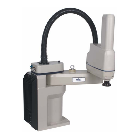
Introduction Product Description Adept Cobra i600/i800 Robots The Adept Cobra i600 and i800 robots are four-axis SCARA robots (Selective Compliance Assembly Robot Arm). See the following figure. Joints 1, 2, and 4 are rotational; Joint 3 is translational. See Figure 1-2 for a description of the robot joint locations. -
Page 16: Adept Amps-In-Base (Aib)
• Digital feed-forward design maximizes efficiency, torque, and velocity • Temperature sensors for all amplifiers and motors for maximum reliability and easy troubleshooting AIB on Adept Cobra i600 Robot Figure 1-3. Adept AIB Adept Cobra i600/i800 Robot User’s Guide, Rev E... -
Page 17: Installation Overview
1. Click on the appropriate .zip file. You are prompted to Open or Save the file. 2. Click Open to open the file and display the archive contents. 3. Double-click on a .pdf file to open it. Adept Cobra i600/i800 Robot User’s Guide, Rev E... -
Page 18: How Can I Get Help
To locate information on a specific topic, use the Document Library search engine on the ADL main page. To view a list of available product documentation, select the Document Titles option. Adept Cobra i600/i800 Robot User’s Guide, Rev E... -
Page 19: Safety
This indicates a situation which, if not avoided, could result in damage to the equipment. NOTE: Notes provide supplementary information, emphasize a point or procedure, or give a tip for easier operation. Adept Cobra i600/i800 Robot User’s Guide, Rev E... -
Page 20: Warning Labels On The Robot
Figure 2-3 show the warning labels on the Adept Cobra i-series robots. Figure 2-1. Electrical and Thermal Warning Labels on AIB Chassis Figure 2-2. Thermal Warning Label on Underside of Inner Link Adept Cobra i600/i800 Robot User’s Guide, Rev E... -
Page 21: Figure 2-3. Warning Label On Encoder Cables
J4-ENC encoder cable connectors from their sockets. If they are removed, the calibration data will be lost and the robot must be run through a factory recalibration process, which requires special software and tools. Adept Cobra i600/i800 Robot User’s Guide, Rev E... -
Page 22: Precautions And Required Safeguards
See Chapter 6 for information on safe and effective use of the robot. Front Panel Location Ensure that the front panel is located outside of the workcell. Adept Cobra i600/i800 Robot User’s Guide, Rev E... -
Page 23: Impact And Trapping Points
Instructions for Emergency Movement without Drive Power In an emergency, when power is removed from the system, the arm can be moved manually. Emergency Recovery Procedures In an emergency, follow your internal procedures for emergency recovery of systems. Adept Cobra i600/i800 Robot User’s Guide, Rev E... -
Page 24: Additional Safety Information
Rue de Varembe 3 900 Victors Way PO Box 131 PO Box 3724 CH-1211 Geneva 20 Ann Arbor, MI 48106 Switzerland Phone 41 22 919-0211 Phone 313-994-6088 Fax 41 22 919-0300 Fax 313-994-3338 http://www.iec.ch http://www.robotics.org Adept Cobra i600/i800 Robot User’s Guide, Rev E... -
Page 25: Risk Assessment
(see “Safety Equipment for Operators” on page and carry the T2 pendant. Therefore, exposure of personnel to hazards related to the robot is limited (seldom and/or short exposure time). Adept Cobra i600/i800 Robot User’s Guide, Rev E... -
Page 26: Severity Of Injury
Arm Power is on. Examples of alternative methods of programming include: 1. Programming from outside the safety barrier. 2. Programming with Arm Power off. 3. Copying a program from another (master) robot. 4. Off-line or CAD programming. Adept Cobra i600/i800 Robot User’s Guide, Rev E... -
Page 27: Control System Behavior Category
Operator and production tooling when the robot is operated in Manual Mode. The standard control system meets or exceeds the requirements imposed by the EN 954 specified Category 1 level of safety. Adept Cobra i600/i800 Robot User’s Guide, Rev E... -
Page 28: Intended Use Of The Robots
(see Section 2.8 on page 30). The Adept Cobra i600 and i800 robots are intended for use in parts assembly and material handling for payloads less than 5.5 kg (12.1 lb). WARNING: For safety reasons, it is prohibited to make... -
Page 29: Robot Modifications
• Modifying, including drilling or cutting, any robot casting. • Modifying any robot electrical component or printed-circuit board. • Routing additional hoses, air lines, or wires through the robot. • Modifications that compromise EMC performance, including shielding. Adept Cobra i600/i800 Robot User’s Guide, Rev E... -
Page 30: Transport
90 dB (A) under worst-case conditions. Typical values will be lower, depending on payload, speed, acceleration, and mounting. Appropriate safety measures should be taken, such as ear protection and display of a warning sign. Adept Cobra i600/i800 Robot User’s Guide, Rev E... -
Page 31: 2.10 Thermal Hazard
• Skilled persons have technical knowledge or sufficient experience to enable them to avoid the dangers, electrical and/or mechanical. • Instructed persons are adequately advised or supervised by skilled persons to enable them to avoid the dangers, electrical and/or mechanical. Adept Cobra i600/i800 Robot User’s Guide, Rev E... -
Page 32: 2.13 Safety Equipment For Operators
The system must be protected against unauthorized use. Restrict access to the keyboard and the pendant by locking them in a cabinet or use another adequate method to prevent access to them. Adept Cobra i600/i800 Robot User’s Guide, Rev E... -
Page 33: 2.15 Safety Aspects While Performing Maintenance
Press any E-Stop button (a red push-button on a yellow background/field) and then follow the internal procedures of your company or organization for an emergency situation. If a fire occurs, use CO to extinguish the fire. Adept Cobra i600/i800 Robot User’s Guide, Rev E... -
Page 35: Robot Installation
The i600 robot weighs 41 kg (90 lb) and the i800 weighs 43 kg (95 lb) with no options installed. Eyebolt for lifting robot after robot has been unbolted from the transportation pallet. Place forklift or pallet-jack here. Figure 3-1. Cobra Robot on a Transportation Pallet Adept Cobra i600/i800 Robot User’s Guide, Rev E... -
Page 36: Unpacking And Inspecting The Adept Equipment
Before unbolting the robot from the shipping pallet, fold the outer arm against the Joint 2 hardstops to help centralize the center of gravity. The robot must always be shipped in an upright orientation. Adept Cobra i600/i800 Robot User’s Guide, Rev E... -
Page 37: Environmental And Facility Requirements
Mounting the Robot Mounting Surface The Adept Cobra i600 and i800 robots are designed to be mounted on a smooth, flat, level surface. The mounting structure must be rigid enough to prevent vibration and flexing during robot operation. Adept recommends a 25 mm (1 in.) thick steel plate mounted to a rigid steel tube frame. -
Page 38: Robot Mounting Procedure
Retain these bolts for possible later relocation of the equipment. 4. Lift the robot and position it directly over the mounting surface. 5. Slowly lower the robot while aligning the base and the tapped mounting holes in the mounting surface. Adept Cobra i600/i800 Robot User’s Guide, Rev E... - Page 39 Chapter 7 for periodic maintenance. Table 3-2. Mounting Bolt Torque Specifications Standard Size Specification Torque Metric M12 x P1.75 ISO Property Class 8.8 85 N•m 7/16-14 UNC SAE Grade 5 63 lb•ft Adept Cobra i600/i800 Robot User’s Guide, Rev E...
-
Page 40: Connectors On The Robot Interface Panel
200/240 VAC - for connecting 200-240 VAC, single-phase, input power to the robot. The mating connector is provided. XSLV - not used in a Cobra i600/i800 robot system. SmartServo 1/2 - not used in a Cobra i600/i800 robot system. RS-232 - for connecting a user-supplied computer, running Adept ACE software. (DB-9, male). -
Page 41: System Installation
User-supplied AC Power Cable - to supply AC User-supplied power to 24 VDC Power Supply RS-232 Null Modem Serial Cable, 04116-001 90565-000 Standard, iCobra 5 meter, for connecting user-supplied PC to robot Adept Cobra i600/i800 Robot User’s Guide, Rev E... -
Page 42: System Cable Diagram
(200-240 VAC 1 ) XPANEL RS-232 AC Power 200-240 VAC Cable 10 A User-Supplied PC single-phase running Adept ACE RS-232 Null Modem Cable for Robot to PC Connection Figure 4-1. iCobra System Cable Diagram Adept Cobra i600/i800 Robot User’s Guide, Rev E... -
Page 43: Cable Connections To The Robot
Connect the T1/T2 Adapter Cable to the matching connector on the T2. Connecting User-Supplied PC to Robot The Adept Cobra i600/i800 robots must be connected to a user-supplied PC for setup, control, and programming. The user loads the Adept ACE software onto the PC and connects it to the robot via an RS-232 serial cable. -
Page 44: Pc Requirements
4-2. If Autoplay is disabled, you will need to manually start the CD-ROM. NOTE: The online document that describes the installation process opens in the background when you select one of software installation steps below. Adept Cobra i600/i800 Robot User’s Guide, Rev E... -
Page 45: Figure 4-2. Adept Ace Cd-Rom Startup Menu
3. The Adept ACE Setup wizard opens - see Figure 4-4 Figure 4-5. Follow the instructions as you step through the installation process. Figure 4-3. Setup Welcome Screen Figure 4-4. Ready-to-Install Screen Adept Cobra i600/i800 Robot User’s Guide, Rev E... -
Page 46: Figure 4-5. Install Screen
5. After closing the Adept ACE Setup wizard, click Exit on the CD-ROM menu and proceed to the Start-up Procedure. NOTE: You will have to restart the PC after installing Adept ACE. Adept Cobra i600/i800 Robot User’s Guide, Rev E... -
Page 47: Connecting 24 Vdc Power To Robot
Table 4-2. Recommended 24 VDC Power Supplies Vendor Name Model Ratings XP Power JMP160PS24 24 VDC, 6.7 A, 160 W AstroDyne SP-150-24 24 VDC, 6.3 A, 150 W Mean Well SP-150-24 24 VDC, 6.3 A, 150 W Adept Cobra i600/i800 Robot User’s Guide, Rev E... -
Page 48: 24 Vdc To Robot
2. Plug the mating connector end of the 24 VDC cable into the 24 VDC connector on the interface panel on the back of the robot. The cable shield should be connected to the ground point on the interface panel. Adept Cobra i600/i800 Robot User’s Guide, Rev E... -
Page 49: Figure 4-7. User-Supplied 24 Vdc Cable
If the power supply does not come with an AC power cable, you will have to build one. The cable should be at least 18 AWG, 3 wire, rated for 300 V. Refer to the 24 VDC power supply you are using for AC input requirements. Adept Cobra i600/i800 Robot User’s Guide, Rev E... -
Page 50: Connecting 200-240 Vac Power To Robot
For short durations (100 ms) Table 8-1 on page 125 for details on Adept cycle. NOTE: The Adept robot system is intended to be installed as a piece of equipment in a permanently-installed system. Adept Cobra i600/i800 Robot User’s Guide, Rev E... -
Page 51: Figure 4-8. Typical Ac Power Installation With Single-Phase Supply
AC Power Cable Adept Cobra L = Line s600/s800 and N = Neutral i600/i800 Robots E = Earth Ground 1 Ø 200–240 VAC Figure 4-8. Typical AC Power Installation with Single-Phase Supply Adept Cobra i600/i800 Robot User’s Guide, Rev E... -
Page 52: Details For Ac Mating Connector
The supplied plug is internally labeled for the AC power connections (L, E, N). Table 4-6. AC Mating Connector Details AC Connector details AC in-line power plug, straight, female, screw terminal, 10 A, 250 VAC Qualtek P/N 709-00/00 Digi-Key P/N Q217-ND Adept P/N 02710-000 Adept Cobra i600/i800 Robot User’s Guide, Rev E... -
Page 53: Procedure For Creating 200-240 Vac Cable
52. Do not turn on AC power at this time. 2. Plug the AC connector into the AC power connector on the interface panel on the robot. 3. Secure the AC connector with the locking latch. Adept Cobra i600/i800 Robot User’s Guide, Rev E... -
Page 54: Grounding The Adept Robot System
Figure 4-11. Ground Point on Robot Base Robot-Mounted Equipment Grounding The following parts of an Adept Cobra i600/i800 robot are not grounded to protective earth: the Joint 3 quill and the tool flange. If hazardous voltages are present at any user-supplied robot-mounted equipment or tooling, you must install a ground connection from that equipment/tooling to the ground point on the robot base. - Page 55 XUSR connector on the AIB XPANEL cable. There is a detailed section on Emergency Stop Circuits and diagrams on recommended E-Stop configurations. Adept Cobra i600/i800 Robot User’s Guide, Rev E...
- Page 56 Chapter 4 - System Installation Adept Cobra i600/i800 Robot User’s Guide, Rev E...
-
Page 57: Optional Equipment Installation
5. Slide the flange down slowly until it is off the shaft. Be careful not to lose the ball bearing (3.5 mm) that is between the flange and shaft, behind the setscrew. Adept Cobra i600/i800 Robot User’s Guide, Rev E... -
Page 58: Installing The Flange
NOTE: The DeviceNet feature is not operational in the Cobra i-series robot. The connectors for DeviceNet are wired through the robot, and can be used if the user is supplying the control software for DeviceNet. Adept Cobra i600/i800 Robot User’s Guide, Rev E... -
Page 59: User Electrical Lines
1&2, 3&4, 5&6, ..., 23&24. Maximum current per line: 1 Amp. 6 mm Air Lines 4 mm Air Lines DeviceNet User Electrical 4 mm Air Line Figure 5-3. User Connectors on Joint 2 Adept Cobra i600/i800 Robot User’s Guide, Rev E... -
Page 60: Internal User Connectors
SOLND Connector Figure 5-5. SOLND Connector Adept Cobra i600/i800 Robot User’s Guide, Rev E... -
Page 61: Solnd Connector
Pin # Description Pin Location Output signal 11 Ground Output signal 12 Ground OP3/4 Connector as viewed on robot Mating Connector: AMP/Tyco #172167-1, 4-pin Mini-Universal Mate-N-Lok AMP/Tyco #770985-1, Pin Contact, Mini-Univ. Mate-N-Lok Adept Cobra i600/i800 Robot User’s Guide, Rev E... -
Page 62: Eoapwr Connector
Table 5-4 current specs) Ground 24 VDC (see Table 5-4 current specs) EOAPWR Connector Ground as viewed on robot Mating Connector: AMP/Tyco #172167-1, 4-pin Mini-Universal Mate-N-Lok AMP/Tyco #770985-1, Pin Contact, Mini-Univ. Mate-N-Lok Adept Cobra i600/i800 Robot User’s Guide, Rev E... -
Page 63: Internal User Connector Output Specifications
The user must enable this function using the Configuration Manager (see below), and connect a normally-closed circuit to pins 1 and 2. When the circuit is opened, the system will stop in an E-Stop condition. See Figure 5-7. Adept Cobra i600/i800 Robot User’s Guide, Rev E... -
Page 64: Figure 5-7. Internal E-Stop Connector Circuit
1. Double-click the iCobra object in the Folder pane of the Workspace Explorer. 2. In the object editor, select Configure > Configuration Manager. See the following figure. Figure 5-8. Selecting the Configuration Manager Adept Cobra i600/i800 Robot User’s Guide, Rev E... -
Page 65: Mounting Locations For External Equipment
67). The signals actuating the valves are directly switchable from MicroV utilizing software signals 9 and 10. Each driver is designed to handle 24 VDC solenoids at a nominal 75 mA per valve. Adept Cobra i600/i800 Robot User’s Guide, Rev E... -
Page 66: Tools Required
Remove two screws on the top and remove the cover. 3. Connect the Internal Solenoid Valve Cable assembly to the Solenoid Manifold assembly, by plugging the SOL 1 connector into Valve 1 and SOL 2 into Valve 2. Adept Cobra i600/i800 Robot User’s Guide, Rev E... -
Page 67: Figure 5-9. Solenoid Mounting Bracket With Connector And Spare Air Line
Joint 2 cover to the air intake coupling mentioned above. 7. Plug the connector plug into the female connector jack (marked SOLND) on the bracket. 8. Use cable ties, as needed, to secure the air line to the bracket. Adept Cobra i600/i800 Robot User’s Guide, Rev E... -
Page 68: Figure 5-10. Solenoid Placement Using Mounting Hardware
Figure 5-11. Removing the Cable Strap Plate 12. Remove the four screws for the Joint 1 cover and lift the cover up so you have access to the tubing under the cover. See Figure 5-12. Adept Cobra i600/i800 Robot User’s Guide, Rev E... -
Page 69: Figure 5-12. Connecting Spare Air Line To User Connector
.SIGNAL 9 .SIGNAL 10 WARNING: The robot air pressure may be disconnected until this test has been done to prevent unsecured pneumatic lines from accidentally injuring personnel. Adept Cobra i600/i800 Robot User’s Guide, Rev E... -
Page 70: Installing Adjustable Hardstops
Configuration Manager utility. See the online help for more details on this utility. 1. Double-click the iCobra object in the Folder pane of the Workspace Explorer. 2. In the object editor, select Configure > Configuration Manager. Adept Cobra i600/i800 Robot User’s Guide, Rev E... -
Page 71: Figure 5-14. Configuration Manager - Modifying Joint 1 Limits
7. Select the required options for saving joint limit values to temporary or permanent memory. For more information on saving changes, click Help 8. Click Write to apply and save the changes. Adept Cobra i600/i800 Robot User’s Guide, Rev E... -
Page 72: Joint 2 Adjustable Hardstops
1. Slide the two adjustable hardstop plates into the space between inner and outer links. See Figure 5-17. Looking up at the inner link from underneath, align the holes in the plates with the holes in the inner link - see Figure 5-19 on page Adept Cobra i600/i800 Robot User’s Guide, Rev E... -
Page 73: Figure 5-17. Joint 2 Adjustable Hardstop Locations
Figure 5-18. Fixed Hardstop Device for Joint 2 4. Use a 3 mm Allen wrench to install two supplied M4 x 10 screws to secure the hardstop device. Tighten the screws to a torque of 2.5 N·m (22 in·lb). Adept Cobra i600/i800 Robot User’s Guide, Rev E... -
Page 74: Figure 5-19. Screw Locations For Joint 2 Adjustable Hardstops
Configuration Manager utility. See the online help for more details on this utility. 1. Double-click the iCobra object in the Folder pane of the Workspace Explorer. 2. In the object editor, select Configure > Configuration Manager. Adept Cobra i600/i800 Robot User’s Guide, Rev E... -
Page 75: Figure 5-20. Configuration Manager - Modifying Joint 2 Limits
9. Once the joint limits have been changed and written to memory, the system is ready to use with the new limits in place. NOTE: With both adjustable hardstop plates installed, Joint 2 has a maximum range of motion of 160°. Adept Cobra i600/i800 Robot User’s Guide, Rev E... - Page 76 Chapter 5 - Optional Equipment Installation Adept Cobra i600/i800 Robot User’s Guide, Rev E...
-
Page 77: System Operation
See the following table: Table 6-2. Legacy Robot Status LED Definition LED Status Description 24 VDC not present Green, Slow Blink High Power Disabled Adept Cobra i600/i800 Robot User’s Guide, Rev E... -
Page 78: Status Panel Fault Codes
Motor Stalled (Joint #) IO Blox Fault (Address #) Non-Volatile Memory AC Power Fault Power System Fault (Code #) Duty Cycle Exceeded (Joint #) Processor Overloaded Encoder Fault (Joint #) RSC Fault Adept Cobra i600/i800 Robot User’s Guide, Rev E... -
Page 79: Using The Brake Release Button
3 may drop to the bottom of its travel. To prevent possible damage to the equipment, make sure that Joint 3 is supported when releasing the brake and verify that the end-effector and other installed tooling is clear of all obstructions. Adept Cobra i600/i800 Robot User’s Guide, Rev E... -
Page 80: Front Panel
To operate without a Front Panel, the user must supply the equivalent circuits. See “Remote Front Panel or User-Supplied for a summary of connections required to Replacement” on page 95 replace the Front Panel. Adept Cobra i600/i800 Robot User’s Guide, Rev E... -
Page 81: Connecting Digital I/O To The System
I/O capacity, to four IO Blox devices per robot. Guide connects to robot. You can combine up to four IO Blox devices to increase capacity by 32 inputs and 32 outputs. Adept Cobra i600/i800 Robot User’s Guide, Rev E... -
Page 82: Figure 6-4 Connecting Digital I/O To The System
IO Blox 2 Inputs 1041 - 1048 Outputs 0041 - 0048 IO Blox 3 Inputs 1049 - 1056 Outputs 0049 - 0056 IO Blox 4 Inputs 1057 - 1064 Outputs 0057 - 0064 Adept Cobra i600/i800 Robot User’s Guide, Rev E... -
Page 83: Using Digital I/O On Robot Xio Connector
XIO 26-pin female Output 1 0001 connector on Robot Interface Panel Output 2 0002 Output 3 0003 Output 4 0004 Output 5 0005 Output 6 0006 Output 7 0007 Output 8 0008 Adept Cobra i600/i800 Robot User’s Guide, Rev E... -
Page 84: Xio Input Signals
5 µsec maximum Software scan rate/response time 16 ms scan cycle/32 ms max response time NOTE: The input current specifications are provided for reference. Voltage sources are typically used to drive the inputs. Adept Cobra i600/i800 Robot User’s Guide, Rev E... -
Page 85: Figure 6-5 Typical User Wiring For Xio Input Signals
This guarantees that the inputs will not be turned on by the leakage current from the outputs. This is useful in situations where the outputs are looped-back to the inputs for monitoring purposes. Adept Cobra i600/i800 Robot User’s Guide, Rev E... -
Page 86: Xio Output Signals
Output voltage at inductive load demag turnoff (I = 0.5 A, Load = 1 mH) 0.7 A ≤ I ≤ 2.5 A DC short circuit current limit ≤ 4 A Peak short circuit current ovpk Adept Cobra i600/i800 Robot User’s Guide, Rev E... -
Page 87: Xio Breakout Cable
04465-000, and the length is 5 M (16.4 ft). Table 6-9 on page 88 for the wire chart on the cable. NOTE: this cable is not compatible with the XIO Termination Block. Figure 6-7 Optional XIO Breakout Cable Adept Cobra i600/i800 Robot User’s Guide, Rev E... - Page 88 XIO Breakout Cable Output 2 Pink/Black Output 3 Light Blue Output 4 Light Blue/Black Output 5 Light Green Output 6 Light Green/Black Output 7 White/Red Output 8 White/Blue Shell Shield Adept Cobra i600/i800 Robot User’s Guide, Rev E...
-
Page 89: Connecting Customer-Supplied Safety And Power Control Equipment
Not supported on Cobra i-series robot 9,22 Not supported on Cobra i-series robot 10,23 Not supported on Cobra i-series robot 11,12, No connection 13, 24, Pin 13 Pin 1 XUSR Pin 25 Pin 14 Adept Cobra i600/i800 Robot User’s Guide, Rev E... - Page 90 Table 6-12. Remote T2 Pendant Connections on the XMCP Connector Pin XMCP Pin T2 Description (15-Pin D-Sub) (16-Pin CPC) T2 E-Stop PB CH 1 2,10 11,12 T2 E-Stop PB CH 2 Adept Cobra i600/i800 Robot User’s Guide, Rev E...
- Page 91 Serial GND/Logic GND T2 TXD: “Micro V to MCP TXD” T2 RXD: “Micro V to MCP RXD” No connection No connection Shield Shield GND 24 V (used by T2 Power Adapter) No connection Adept Cobra i600/i800 Robot User’s Guide, Rev E...
-
Page 92: Figure 6-8 Cobra I600/I800 E-Stop Circuit Connections
Force-Guided Relay bulb (XPANEL-13) Cyclic Check Control Circuit XFP-13 (XPANEL-21) XFP-14 (XPANEL-20) Single-Phase High Power to AC Input Amplifiers 200-240 VAC Force-Guided Force-Guided Relay Relay Figure 6-8 Cobra i600/i800 E-Stop Circuit Connections Adept Cobra i600/i800 Robot User’s Guide, Rev E... -
Page 93: Emergency Stop Circuits
Figure 6-9 Front Panel Schematic Emergency Stop Circuits The Cobra i600/i800 robot provides connections for Emergency Stop (E-Stop) circuits on the XUSR and XFP connectors. This gives the robot system the ability to slave E-Stop functionality from a remote location using voltage-free contacts. See... -
Page 94: Remote Manual Mode
Thus, it is important that the remote High Power push button be located outside of the workspace of the robot. Adept Cobra i600/i800 Robot User’s Guide, Rev E... -
Page 95: High Power On/Off Lamp
Front Panel’s signals, use relay contacts instead of switches. See Figure 6-9 on page 93 for a schematic drawing of the Front Panel and Table 6-11 on page 90 for a summary of connections and pin numbers. Adept Cobra i600/i800 Robot User’s Guide, Rev E... -
Page 96: Turning On The System
System Installation Checks Verify that the installation procedures in Section 4.3 through Section 4.8 have been completed. User-Supplied Safety Equipment Checks Verify that all user-supplied safety equipment and E-Stop circuits are installed correctly. Adept Cobra i600/i800 Robot User’s Guide, Rev E... -
Page 97: Turning On Power And Starting Adept Ace
5. Turn on the user-supplied PC and start Adept ACE. Double-click the Adept ACE icon on your Windows desktop, or, from the Windows Start menu bar, select Start > Programs > Adept Technology > Adept ACE > Adept ACE. 6. Connect a serial cable from the PC to the robot. -
Page 98: Enabling High Power
NOTE: This start-up procedure using the Diagnostics Wizard is also shown in the Adept Cobra i600/i800 Robot Quick Setup Guide. 1. Double-click the iCobra object in the Folder pane of the Workspace Explorer. Adept Cobra i600/i800 Robot User’s Guide, Rev E... -
Page 99: Figure 6-12. Selecting The Diagnostics Wizard
The following screen opens: Figure 6-13 Adept DIagnostics Wizard 3. The Wizard verifies the workcell configuration, to confirm all equipment is installed correctly. Click Next to continue to the Enable Power sequence. Adept Cobra i600/i800 Robot User’s Guide, Rev E... -
Page 100: Figure 6-14 Diagnostics Wizard Enable Power Sequence
NOTE: The Front Panel button must be pressed within 10 seconds. Switch set to Auto Mode Press High Power button when blinking (within 10 seconds) Figure 6-15 High Power Button on Front Panel Adept Cobra i600/i800 Robot User’s Guide, Rev E... -
Page 101: Figure 6-16 Diagnostics Wizard Complete
This step turns on high power to the robot motors and calibrates the robot. • The Robot Status LED glows amber, or, on older iCobras, blinks green rapidly. • The code on the Robot Diagnostic Panel displays ON (see Figure 6-2 on page 78). Adept Cobra i600/i800 Robot User’s Guide, Rev E... -
Page 102: Figure 6-18 Robot Jog Control Window
In the Mode section, click Joint. By default, Comp will be selected. c. Use the Robot Jog Control arrows to move Joint 1 a short distance in both directions. Repeat for Joints 2, 3, and 4. See the following figure. Adept Cobra i600/i800 Robot User’s Guide, Rev E... -
Page 103: Verifying E-Stop Functions
Learning to Program the Adept Cobra i-Series Robot To learn how to use and program the robot, go to the Adept ACE and MicroV+ online documentation in the Adept Document Library, to find information on basic operation and programming. Adept Cobra i600/i800 Robot User’s Guide, Rev E... - Page 104 Chapter 6 - System Operation Adept Cobra i600/i800 Robot User’s Guide, Rev E...
-
Page 105: Maintenance
Lubricate Joint 3 (Z-axis) ball screw/spline 3 months Replace Encoder battery 5 to 10 Section 7.8 years For robot models with the smaller, rectangular batteries, inspect the battery every 18 months to 3 years. Adept Cobra i600/i800 Robot User’s Guide, Rev E... -
Page 106: Checking Safety Systems
3. Test operation of barrier interlocks, etc. Checking Robot Mounting Bolt Torque Check the tightness of the base mounting bolts every 6 months. Tighten to 85 N·m (63 ft·lb). Also check the tightness of all cover plate screws. Adept Cobra i600/i800 Robot User’s Guide, Rev E... -
Page 107: Checking Robot For Oil Around Harmonic Drive
Lithium Soap, Synthetic Hydrocarbon Adept part number: 85139-00002 CAUTION: Using improper lubrication products on the Adept Cobra i600 or i800 robot may cause damage to the robot. Lubrication Procedure 1. Turn off main power to the robot. 2. Remove the outer link cover by removing six screws located on the sides and top of the cover. - Page 108 8. Apply a thin film of grease to any grooves of the ball screw that you did not reach Step 9. Move Joint 3 up and down several times to spread the grease evenly. 10. Remove 24 VDC power from the robot. 11. Reinstall the outer link cover. Adept Cobra i600/i800 Robot User’s Guide, Rev E...
-
Page 109: Figure 7-1. Lubrication Of Joint 3 Quill
Lube Point B Top View Looking Down NOTE: Apply grease to the three vertical grooves Vertical Groove and the spiral groove Lube Point C Section A-A Figure 7-1. Lubrication of Joint 3 Quill Adept Cobra i600/i800 Robot User’s Guide, Rev E... -
Page 110: Replacing The Aib Chassis
NOTE: The screw does not need to be completely removed in order to remove the chassis, as this screw is captured on the chassis heat sink. Securing Screw on AIB Figure 7-2. Securing Screw on AIB Chassis Adept Cobra i600/i800 Robot User’s Guide, Rev E... -
Page 111: Figure 7-3. Opening And Removing Aib Chassis
12. Carefully disconnect the J27 cable from the J27 connector on the PMAI, by disengaging the securing latches. 13. Carefully disconnect the J28 cable from the J28 connector on the PMAI, by disengaging the securing latches. Adept Cobra i600/i800 Robot User’s Guide, Rev E... -
Page 112: Installing A New Aib Chassis
6. Carefully connect the J27 cable to the J27 connector on the PMAI, and engage the securing latches. 7. Carefully connect the J11 cable to the J11 connector on the PMAI, and engage the securing latches. Adept Cobra i600/i800 Robot User’s Guide, Rev E... -
Page 113: Figure 7-7. Installing Aib Chassis In Robot Base
18. Install MicroV+ on the AIB chassis. 19. Install the application and robot configuration data on the AIB chassis. 20. Once the system has completed booting, test the system for proper operation. Adept Cobra i600/i800 Robot User’s Guide, Rev E... -
Page 114: Replacing Encoder Battery
7. While holding the chassis heat sink, carefully and slowly lower the chassis down (see Figure 7-3 on page 111), so there is access to the battery. See Figure 7-8. Adept Cobra i600/i800 Robot User’s Guide, Rev E... -
Page 115: Figure 7-8. Location Of Encoder Battery
14. Reconnect the 200/240 VAC supply cable to the robot AC input connector. 15. Reconnect the 24 VDC supply cable to the robot +24 VDC input connector. See for locations of connectors. Figure 3-3 on page 40 Adept Cobra i600/i800 Robot User’s Guide, Rev E... - Page 116 Chapter 7 - Maintenance Adept Cobra i600/i800 Robot User’s Guide, Rev E...
-
Page 117: Technical Specifications
Technical Specifications Dimension Drawings Required clearance to open AIB Chassis Required cable clearance Figure 8-1. Adept Cobra i600/s600 Top and Side Dimensions Adept Cobra i600/i800 Robot User’s Guide, Rev E... -
Page 118: Figure 8-2. Adept Cobra I800/S800 Top And Side Dimensions
Chapter 8 - Technical Specifications Required clearance to open AIB Chassis Required cable clearance Figure 8-2. Adept Cobra i800/s800 Top and Side Dimensions Adept Cobra i600/i800 Robot User’s Guide, Rev E... -
Page 119: Figure 8-3. Dimensions Of The Camera Bracket Mounting Pattern
Dimension Drawings +.10 ∅3.0 Cobra s/i600 2X -.03 +.10 ∅3.0 Cobra s/i800 2X -.03 Cobra s/i600 4X M4x0.7-6H Cobra s/i800 4X M4x0.7-6H Figure 8-3. Dimensions of the Camera Bracket Mounting Pattern Adept Cobra i600/i800 Robot User’s Guide, Rev E... -
Page 120: Figure 8-4. Tool Flange Dimensions
.10 mm (.004 in.) R 3.56mm (R 0.140in) 5.08mm (0.20in) M3 X 0.5-6H Thru 4.14 mm (0.163 in.) 1.5 mm (0.059 in.) 6.80 mm (0.268 in.) ˚ Detail A Figure 8-4. Tool Flange Dimensions Adept Cobra i600/i800 Robot User’s Guide, Rev E... -
Page 121: Figure 8-5. External Tooling On Top Of Robot Arm
Dimension Drawings 4X M4x0.7 - 6H Inner Link External Mounting Locations 4X M4x0.7 - 6H Outer Link External Mounting Locations Figure 8-5. External Tooling on Top of Robot Arm Adept Cobra i600/i800 Robot User’s Guide, Rev E... -
Page 122: Figure 8-6. External Tooling On Underside Of Outer Link
Chapter 8 - Technical Specifications 76 - Cobra s/i600 135 - Cobra s/i800 Outer Link - Bottom View 4X M4x0.7-6H Figure 8-6. External Tooling on Underside of Outer Link Adept Cobra i600/i800 Robot User’s Guide, Rev E... -
Page 123: Figure 8-7. Adept Cobra I600/S600 Robot Working Envelope
Maximum Intrusion Contact Radius Minimum 647 mm (25.50 in.) Radial Reach 162.6 mm (6.40 in.) 105˚ 105˚ 150˚ 150˚ Cartesian Limits 300 mm (11.8 in.) Figure 8-7. Adept Cobra i600/s600 Robot Working Envelope Adept Cobra i600/i800 Robot User’s Guide, Rev E... -
Page 124: Figure 8-8. Adept Cobra I800/S800 Robot Working Envelope
847.3 mm (33.36 in.) 800 mm (31.50 in.) Minimum Radial Reach 163.6 mm (6.44 in.) 105˚ 105˚ 157.5˚ 157.5˚ Cartesian Limits 300 mm (11.8 in.) Figure 8-8. Adept Cobra i800/s800 Robot Working Envelope Adept Cobra i600/i800 Robot User’s Guide, Rev E... -
Page 125: Robot Specifications
0.86 sec at 40° C 0.91 sec at 40° C Repeatability x, y ±0.017 mm (±0.00067 in.) ±0.017 mm (±0.00067 in.) ±0.003 mm (±0.00012 in.) ±0.003 mm (±0.00012 in.) Theta ±0.019° ±0.019° Adept Cobra i600/i800 Robot User’s Guide, Rev E... - Page 126 ± 157.5° ± 160° Joint 3 0 to 210 mm -5 to 215 mm 0 to 210 mm -5 to 215 mm Joint 4 ± 360° not applicable ± 360° not applicable Adept Cobra i600/i800 Robot User’s Guide, Rev E...
-
Page 127: Cleanroom Robots
Cobra i600/i800 Cleanroom Option Introduction The Adept Cobra i600/i800 Cleanroom Option is a modification to the standard robot that certifies the robot to meet the Class 3 Airborne Particulate Cleanliness Limits as defined by ISO Standard 14644 (Class 10 for Federal Standard 209E). -
Page 128: Specifications
Quill inside diameter The inside diameter of the quill must be plugged by the user’s end-effector in order for sufficient vacuum to develop in the outer link. Adept Cobra i600/i800 Robot User’s Guide, Rev E... -
Page 129: Exclusions And Incompatibilities
3. Remove the upper bellows clamp ring by loosening the screw on the clamp. 4. Slide the old bellows down off of the quill. 5. Install a new bellows, and reverse the steps listed above. Adept Cobra i600/i800 Robot User’s Guide, Rev E... -
Page 130: Lubrication
Ring Tool Flange Figure 9-3. Cleanroom Bellows Replacement Lubrication The upper and lower quill requires lubrication in the same manner as the standard Cobra i600/i800 robot. See Section 7.6 on page 107. Adept Cobra i600/i800 Robot User’s Guide, Rev E... -
Page 131: 10.1 Cobra I800 Ip-65 Classification
The cable seal assembly (04813-000) must be mounted on the back of the robot during the robot installation process. The cable seal assembly is shipped separately from the robot. Figure 10-2 to identify the cable seal parts. Adept Cobra i600/i800 Robot User’s Guide, Rev E... -
Page 132: Installation Procedure
Then pull up on the flange and push it toward the robot. c. Finally push down on the flange to secure it against the housing. See Figure 10-5 for the lower flange in the installed position. Adept Cobra i600/i800 Robot User’s Guide, Rev E... -
Page 133: Figure 10-4. Installing Lower Flange
7. Attach the flange assembly using one M6x20 screw, one M6 lock washer, and one M6 flat washer. See Figure 10-6. Figure 10-6. Upper Flange Installed Adept Cobra i600/i800 Robot User’s Guide, Rev E... -
Page 134: 10.3 Robot Outer Link Cover Removal And Reinstallation
See the label on the side of the outer link cover. CAUTION: Do not loosen these screws any more than 2 turns, because the special clamp nut on the inside of the cover might come loose and fall inside of the robot. Adept Cobra i600/i800 Robot User’s Guide, Rev E... -
Page 135: Cover Reinstallation Procedure
Figure 10-9. IP-65 Robot with Outer Link Cover Removed Cover Reinstallation Procedure 1. Check the cover O-ring around the inner groove of the cover to make sure it is in place and not crimped when installing the cover. Adept Cobra i600/i800 Robot User’s Guide, Rev E... - Page 136 7. Reinstall the collar nut and tighten until secure. 8. Remember to turn on the compressed air supply to the system before restarting the robot. Adept Cobra i600/i800 Robot User’s Guide, Rev E...
-
Page 137: 10.4 Customer Requirements
The bottom face of the flange (mounting surface) is the same as the standard flange, so the dimensions in Figure 8-4 on page 120 are correct. 20.0 12.0 72.2 41.15 76.2 Figure 10-10. Cobra IP-65 Tool Flange Adept Cobra i600/i800 Robot User’s Guide, Rev E... -
Page 138: Pressurizing The Robot
Failure to do this could result in moisture or particle buildup inside the robot and lead to reduced performance or damage to the robot. This will void your warranty. Adept Cobra i600/i800 Robot User’s Guide, Rev E... -
Page 139: 10.5 User Connectors
4 mm Air Line 6 mm Air Line DeviceNet User Electric 4 mm Air Line 2 Spare Air Lines Figure 10-13. IP-65 Internal Connectors with Outer Link Cover Removed Adept Cobra i600/i800 Robot User’s Guide, Rev E... -
Page 140: User Air Lines
The internal air line normally used to supply the solenoid manifold is instead used to provide positive airflow pressure to the bellows/outer link. You can use one of the passive 6 mm user air lines shown in Figure 10-12 Figure 10-13 on page 139. Adept Cobra i600/i800 Robot User’s Guide, Rev E... -
Page 141: 10.6 Maintenance
Accessory Kit. Then install the clamp over the bottom of the bellows, on the bearing ring just above the user flange. Align the mating surfaces of the clamp half-rings with the bellows seam - see Figure 10-15. Tighten the screw to secure the clamp. Adept Cobra i600/i800 Robot User’s Guide, Rev E... -
Page 142: 10.7 Dimension Drawing For Cable Seal Assembly
Figure 10-15. Bellows Clamp Alignment 10.7 Dimension Drawing for Cable Seal Assembly REQUIRED CLEARANCE TO OPEN AIB CONTROLLER WITH THE IP-65 CONNECTOR CABLE SEALING BOX ON IP-65 VERSION ONLY Figure 10-16. Cable Seal Assembly Dimensions Adept Cobra i600/i800 Robot User’s Guide, Rev E... - Page 143 Breakaway ESTOP, see ESTOP connector robot mounting holes breakout cable, XIO tool flange Document Library CD-ROM dowel pin, for keying on end-effectors cable and parts list cable diagram, system cable seal assembly installing on IP-65 robot Adept Cobra i600/i800 Robot User’s Guide, Rev E...
- Page 144 J1, J2 maintenance 105–115 specifications lubricating Joint 3 High Power On/Off Switch, Front Panel replacing cleanroom bellows replacing IP-65 bellows How Can I Get Help? Manual/Automatic Mode switch, Front Panel mechanical specifications Adept Cobra i600/i800 Robot User’s Guide, Rev E...
- Page 145 Power On LED, Front Panel precautions and required safeguards programming, robot protection against unauthorized operation facility overvoltage qualification of personnel related manuals remote Manual Mode control repacking for relocation requirements environmental facility risk assessment RS-232 connector Adept Cobra i600/i800 Robot User’s Guide, Rev E...
- Page 146 XIO Termination Block XMCP connector jumper plug remote pendant connections T1/T2 bypass plug XPANEL connector XSLV connector XUSR connector jumper plug pin-outs Adept Cobra i600/i800 Robot User’s Guide, Rev E...
- Page 147 Index Adept Cobra i600/i800 Robot User’s Guide, Rev E...
- Page 150 5960 Inglewood Drive Pleasanton, CA 94588 P/N: 03589-000, Rev E 925·245·3400...
Need help?
Do you have a question about the Cobra i600 and is the answer not in the manual?
Questions and answers