
Related Manuals for Matrox 4Sight-II


Summary of Contents for Matrox 4Sight-II
- Page 1 Matrox 4Sight-II Installation and Hardware Reference Manual no. 10775-101-0500 March 24, 2003 ox Meteor-II /Digital...
- Page 2 © Copyright Matrox Electronic Systems Ltd., 2003. All rights reserved. Limitation of Liabilities: In no event will Matrox or its suppliers be liable for any indirect, special, incidental, economic, cover or consequential damages arising out of the use of or inability to use the product, user...
-
Page 3: Table Of Contents
Matrox opto-coupling module ........19... - Page 4 Units with Matrox Meteor-II /Multi-Channel ......38 Units with Matrox Meteor-II /Digital....... 39 Units with Matrox Meteor-II /Camera Link .
- Page 5 Removing the Matrox 4Sight-II chassis ........
- Page 6 Part 3: Reference material for all users Chapter 5: Matrox 4Sight-II hardware reference ... . 65 Overview ............66 Motherboard .
- Page 7 Matrox Orion /Standard for 4Sight-II....... 86 Matrox Orion /Dual for 4-Sight-II ....... . . 86 Input channels .
- Page 8 Part 4: Appendices Appendix A: Troubleshooting ......99 What to do if you have a problem ........100 Common problems and solutions .
- Page 9 The Phoenix Phlash utility ........137 Updating the Matrox 4Sight-II VGA BIOS ....... 141 BIOS messages and diagnostic codes .
- Page 10 Auxiliary I/O connector ("Aux. I/O")......178 Matrox opto-coupling module ........179 Pinouts of internal connectors .
-
Page 11: Using This Manual
Matrox Orion modules for 4Sight-II. • The final part is composed of six appendices, which provide useful information regarding Matrox 4Sight-II. They are designed for all users of Matrox 4Sight-II, and include a troubleshooting section, a BIOS reference, technical reference, and a glossary. - Page 12 Using this manual If your Matrox 4Sight-II installation questions are not answered in this reference, Problems? contact your local Matrox representative or the Matrox Imaging Customer Support group; refer to the Product Support section at the back of this reference for email addresses and phone numbers of Matrox’s offices.
-
Page 13: Part 1: Operating Your Matrox 4Sight-Ii Unit
Part 1: Operating your Matrox 4Sight-II unit... -
Page 15: Chapter 1: Before You Begin
Chapter Before you begin This chapter introduces you to the hardware components found on Matrox 4Sight-II. -
Page 16: Overview
Matrox 4Sight-II is a self-contained platform that integrates processing and display, along with image capture, networking, IEEE 1394 capability, and general purpose I/O. Matrox 4Sight-II comes in two basic versions: the integrated-unit version and the motherboard-only version. The integrated-unit version includes a Matrox 4Sight-II motherboard, a DIMM memory module, a mass storage device, and an optional frame grabber, all of which are encased within a metal chassis. - Page 17 In addition, it supports 32-bit (true-color) non-destructive graphics overlay onto live video, for a completely true-color display. The Matrox G450 is capable of output to one or two display devices using Matrox DualHead technology. Various operating systems employ Matrox DualHead technology to simultaneously output their interface on two devices (such as achieving an extended desktop).
-
Page 18: Mass Storage
ATA-44 connectors. Chassis The Matrox 4Sight-II chassis can enclose the Matrox 4Sight-II motherboard, up to three PC/104-Plus boards, an optional 2.5 inch IDE hard drive or flash drive, and fan. Mounting points on the chassis allow the unit to be secured to other... -
Page 19: Memory
24 V. ❖ The Matrox opto-coupling module has been designed for the integrated-unit version of Matrox 4Sight-II, and is normally sold with this version only. However, if you need to use this module with the motherboard-only version of Matrox 4Sight-II, please contact Matrox to obtain important installation specifications and instructions. - Page 20 Matrox Orion /Standard for 4Sight-II. • /Dual. The Matrox Orion /Dual for 4Sight-II features two decoders and a 2 Mbyte buffer, thereby supporting digitization of two asynchronous video streams simultaneously. The /Dual can capture the same signals as the /Standard, but supports twice as many input channels.
-
Page 21: Inspecting Your Matrox 4Sight-Ii Package
Camera Link connectors. The Matrox Meteor-II /Standard and /Multi-Channel frame grabbers can be made especially for your Matrox 4Sight-II unit, in that their video input connector can interface directly with a connector on your unit’s motherboard, which in turn, is hardwired to the external video input connector. -
Page 22: Motherboard-Only Version
Used to connect a 40-pin connector, IDE device to the motherboard. adapter Accessory-device power cable To provide power to certain devices connected to the motherboard. Motherboard-only version If you have purchased the motherboard-only version of Matrox 4Sight-II, your package should contain the following items: Standard package item Details Motherboard... -
Page 23: Additional Components
You might have purchased one or more of the following additional components to complete your unit: Additional component Details Matrox Imaging software Please refer to the software manual for details on Matrox Imaging software packages compatible with Matrox 4Sight-II. Matrox frame grabbers for • Matrox Meteor-II/Standard. -
Page 24: Operating Your Matrox 4Sight-Ii Unit
Light emitting diodes (LEDs) There are a total of six clearly labelled LEDs on the Matrox 4Sight-II unit. • On one side, there are four LEDs: - On (topmost LED). Power on - lights when the unit is on. -
Page 25: Handling Precautions
Turning off the integrated-unit version of Matrox 4Sight-II To turn off the integrated-unit version of Matrox 4Sight-II, push and hold the power button for at least four seconds. While it is being pressed, the unit will shut-off. This feature acts as a safety precaution so that your unit is less likely to be turned off by accident. - Page 26 26 Chapter 1: Before you begin...
-
Page 27: Chapter 2: Connecting Peripherals To The Unit
Chapter Connecting peripherals to the unit This chapter is geared to users who are ready to connect various peripherals to their unit... -
Page 28: Overview
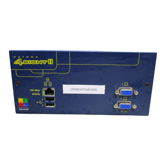
28 Chapter 2: Connecting peripherals to the unit Overview This chapter describes how to connect various devices to the Matrox 4Sight-II unit. Back panel Front panel Auxiliary I/O port Power button (top) IEEE 1394 Serial connectors ports Power connector (bottom) -
Page 29: Connecting Display Devices
1. “NC” = no connection. MIL and MIL-Lite can employ the Matrox DualHead capabilities of the Matrox Using a second G450 graphics controller to use the second display device as an auxiliary display. display In addition, certain operating systems can also make use of other Matrox DualHead features while running. -
Page 30: Connecting A High-Resolution Display Device
1. Connect the first monitor to the top analog VGA connector (connector #1) on the Matrox 4Sight-II unit. If your monitor has a DB-15 connector, use a standard DB-15 to DB-15 cable. If your monitor has 5 BNC-type connectors, use a standard DB-15 to 5-BNC cable. -
Page 31: Connecting A Digital Flat Panel
Connecting NTSC/PAL video output devices You can connect video output devices, such as a TV monitor or VCR to analog VGA connector #2. Matrox 4Sight-II can output both composite (CVBS) and component (Y/C) video in NTSC or PAL formats. It can also output component RGB video with resolutions similar to video in NTSC/PAL formats. -
Page 32: Connecting A Usb Mouse And Keyboard
Matrox 4Sight-II unit. Connecting other USB devices If you are using Matrox 4Sight-II under the Windows 2000 operating system, you can connect other USB devices to the USB connectors. However if you are using your unit under Windows NT, you cannot connect other USB devices. - Page 33 Networking connections If the Matrox 4Sight-II unit is part of a peer-to-peer communication Peer-to-peer configuration, you will have to use a custom-made crossover network cable to communication connect your two units. Peer-to-peer connection for the Matrox 4Sight-II. PC 1 Matrox 4Sight-II...
-
Page 34: Connecting Video Input Devices
It supports up to twelve video input signals and one trigger signal. ❖ Note that the Matrox Orion /Dual for 4Sight-II supports two of these cables, permitting you to connect up to a total of 24 video input signals. - Page 35 External trigger input External trigger input (OPTOTRIG+) External trigger input (OPTOTRIG+) (OPTOTRIG+) The following signals are only available on Matrox Orion /Dual for 4Sight-II when the cable is connected to video input connector 2. VID_IN13 Camera 13 Y (camera 7)
- Page 36 VID_IN8 You can interface up to twelve composite cameras to Matrox Orion /Standard or Connecting to /RGB for 4Sight-II, whereas you can interface up to 24 composite cameras to composite input signals Matrox Orion /Dual for 4Sight-II. To do so: 1.
- Page 37 Connecting video input devices You can interface up to six Y/C cameras to Matrox Orion /Standard or /RGB for Connecting to Y/C 4Sight-II, whereas you can interface up to 12 Y/C cameras to Matrox Orion /Dual input signals for 4Sight-II. In addition to the DBHD44-TO-13BNC cable, you will also need the BNC-TO-SVHS adapter cables.
-
Page 38: Units With Matrox Meteor-Ii /Multi-Channel
1. Connect the BNC wires to each RGB camera using the information from the above table. 2. Attach the DBHD44 connector to the video input connector of Matrox 4Sight-II. You can also use a DBHD44-TO-8BNC/O cable if you need to connect to other... -
Page 39: Units With Matrox Meteor-Ii /Digital
Units with Matrox Meteor-II /Digital To interface video sources to a Matrox Meteor-II /Digital frame grabber (designed for Matrox 4Sight-II), use one or two VHDCI-TO-OPEN cables to connect to the unit’s digital video input connectors. These cables have a VHDCI connector on one side, and are open-ended on the other. -
Page 40: Connecting Ieee 1394 Devices
Please refer to the accompanying software manual for more information on the capabilities and limitations of the IEEE 1394 interface, when using Matrox 4Sight-II under a specific operating system. For further information on the IEEE 1394 specification, consult: • Anderson, Don. FireWire System Architecture. Reading, Massachusetts: Mindshare Inc., 1998. -
Page 41: Connecting Devices To The Auxiliary I/O Interface
Connecting devices to the auxiliary I/O interface Connecting devices to the auxiliary I/O interface If you have purchased the integrated-unit version of Matrox 4Sight-II, you can connect devices to the auxiliary I/O interface connector, located on the back panel of the unit. -
Page 42: Connecting Devices To The Parallel Port Connector
If you have purchased the motherboard-only version of Matrox 4Sight-II, you will have to connect parallel devices to the internal connector of the parallel interface, located on the motherboard. Please refer to Chapter 3: Adding devices to the Matrox 4Sight-II motherboard, for details. -
Page 43: Part 2: Making Motherboard Modifications
Part 2: Making motherboard modifications... -
Page 45: Chapter 3: Adding Devices To The Matrox 4Sight-Ii Motherboard
Chapter Adding devices to the Matrox 4Sight-II motherboard This chapter deals with additions that can be made to the Matrox 4Sight-II motherboard. -
Page 46: Introduction
Internal ATA-44connectors Front Panel If you have purchased the integrated-unit version of Matrox 4Sight-II, the first step in making hardware additions involves removing the chassis cover. Once removed, you will have access to all the connectors located on the motherboard. -
Page 47: Removing The Matrox 4Sight-Ii Chassis
3. With the Matrox 4Sight-II unit laid flat, face the back panel, place your hands on top of the chassis and slowly slide the chassis so that the top and front panels (which are attached) separate from the back and bottom panels (which are also attached). - Page 48 Warning If your Matrox 4Sight-II unit is installed in a factory-provided chassis, be sure to always operate it with the cover on. This ensures that the fan properly removes any heat accumulating in the heat sinks.
-
Page 49: Connecting A Hard Drive, Flash Drive, Or Cd Drive
Connecting a hard drive, flash drive, or CD drive A primary and secondary ATA-44 connector is present on the Matrox 4Sight-II motherboard, each of which allows you to connect one or two IDE devices. The location of the ATA-44 connectors are shown in the diagram below:... -
Page 50: Connecting Devices With A 44-Pin Ata Connector
• A flat-ribbon cable with 44-pin, IDC, female connectors on each side. • A flat-ribbon cable with 40-pin, IDC, female connectors on each side. • A 44-to-40-pin flat ribbon cable adapter (included with your Matrox 4Sight-II package). • An accessory power cable (included with your Matrox 4Sight-II package). - Page 51 • A flat-ribbon cable that has three, 40-pin, IDC, female connectors. • A 44-to-40-pin flat ribbon cable adapter. • A custom power cable. The accessory power cable provided by Matrox will not be adequate, as it has been designed for use by a single device only.
-
Page 52: Connecting Both Types Of Ide Devices
52 Chapter 3: Adding devices to the Matrox 4Sight-II motherboard To connect the devices: 1. Using the three-connector flat-ribbon cable, attach one connector to the 44-to-40 cable adapter, and attach the other two connectors to each device. 2. Using the other flat-ribbon cable, attach one connector to the primary ATA-44 connector, and attach the other connector to the 44-to-40 cable adapter. -
Page 53: Connecting A Pc/104-Plus Board
The following points are critical when connecting additional PC/104-Plus boards to the Matrox 4Sight-II motherboard: • The voltage I/O pins on the Matrox 4Sight-II PC/104-Plus connector are set to 3.3 V. • If you are connecting a standard PC/104 board, it must be the top module, since it does not include the PCI bus. - Page 54 1 or 5 2 or 6 The switch position for the Matrox Orion module for 4Sight-II is 0, as it is always the bottom module. This switch position cannot be modified. • You can simultaneously grab images from cameras attached to different frame Using multiple grabbers.
-
Page 55: Removing And Installing Memory
The Matrox 4Sight-II motherboard features one 168-pin DIMM slot. This slot can support SDRAM modules up to 1 Gbyte in size. This section describes how to remove and install an SDRAM module. Matrox 4Sight-II supports 3.3 V, unbuffered, PC/100-compliant SDRAM DIMMs. -
Page 56: Adjusting Your New Memory Settings
56 Chapter 3: Adding devices to the Matrox 4Sight-II motherboard Adjusting your new memory settings If the Matrox Imaging Library (MIL) or one of its derivatives is installed in your unit, you must adjust your unit’s new memory settings using the MIL Configuration utility. -
Page 57: Connecting Devices To The Internal Connector Of The Parallel Interface
Connecting devices to the internal connector of the parallel interface Connecting devices to the internal connector of the parallel interface If you have purchased the motherboard-only version of Matrox 4Sight-II, you will have to connect parallel devices to the internal connector of the parallel interface, located on the motherboard. - Page 58 58 Chapter 3: Adding devices to the Matrox 4Sight-II motherboard...
-
Page 59: Chapter 4: Installing The Matrox 4Sight-Ii Motherboard In A Custom Chassis
Chapter Installing the Matrox 4Sight-II motherboard in a custom chassis This chapter provides some guidelines for installing the Matrox 4Sight-II motherboard in a custom chassis. -
Page 60: Overview
In addition to this chapter, any specific instructions included with your custom components should also be read. If you purchased the Matrox 4Sight-II integrated unit, you can skip this chapter. Warning To protect the Matrox 4Sight-II motherboard against static electricity, follow the precautions mentioned in Handling precautions, found in Chapter 1. -
Page 61: Custom Fan
Custom fan Custom fan You can use any fan that provides at least 18 cfm (0.5 m /min.) of air flow through the CPU heat sink. Due to the heat sink’s convoluted fins, the fan must be placed on one side of the heat sink, as illustrated in the diagram below. This will ensure proper airflow through the fins, resulting in an efficient removal of accumulated heat. -
Page 62: Custom Power Supply
62 Chapter 4: Installing the Matrox 4Sight-II motherboard in a custom chassis Custom power supply The power connector on the stand-alone Matrox 4Sight-II motherboard is a 7-pin locking connector, with pin 1 physically located closest to the rear of the motherboard. -
Page 63: Part 3: Reference Material For All Users
Part 3: Reference material for all users... -
Page 65: Chapter 5: Matrox 4Sight-Ii Hardware Reference
Chapter Matrox 4Sight-II hardware reference This chapter provides hardware descriptions of Matrox 4Sight-II. -
Page 66: Overview
Ports Controller Plus PC/104- (ISA) Plus 10/100BaseT PC/104- (32-bit/33 MHz PCI) Expansion Ethernet Module** Controller (optional) Matrox VIP *Opto-isolated requires Matrox opto-coupling module **Matrox Orion modules for 4Sight-II interface with the motherboard using Matrox VIP, not ISA or PCI interfaces... -
Page 67: Processing
• A computer memory (DRAM) controller, which can support a 64-bit, 66/100 Mhz main memory interface. • A 2X AGP interface, which can execute data transfers with the Matrox G450 graphics controller, at speeds up to 533 Mbytes/sec. • A PCI interface, which can transfer data over the 32-bit PCI bus at rates up to 133 Mbytes/sec. - Page 68 68 Chapter 5: Matrox 4Sight-II hardware reference • A serial port controller. • A digital audio controller. • Power management features. The VT82C686B south bridge interfaces with the BIOS, via an 8-bit ISA bus. In addition, it interfaces with the 440BX north bridge via the 32-bit PCI local bus.
-
Page 69: Memory
Display Display capabilities are made possible due to the Matrox G450 graphics controller, which features a 2X, 32-bit, master AGP Host interface, a 360 MHz primary display RAMDAC, a 200 MHz secondary RAMDAC, a TV/video encoder, a TMDS transmitter, and 32 Mbytes DDR SDRAM. -
Page 70: Video Input Port
70 Chapter 5: Matrox 4Sight-II hardware reference Video input port Digitized data from the Matrox Orion module for 4Sight-II is transferred from its pixel converter to the Matrox G450 graphics controller along an 8-bit video input port (VIP) bus. AGP interface Display data is transferred along a 2X AGP interface, between the Matrox G450 graphics controller and the chipset’s north bridge. -
Page 71: Underlay/Overlay Capabilities
Display Underlay/overlay capabilities Using the 32 Mbyte frame buffer, the Matrox G450 chip can allocate both an overlay and underlay frame buffer surface. It can then combine these frame buffers to display a live video window on your Windows desktop with non-destructive annotations. -
Page 72: Mass Storage
Mass storage Hard disk drive To store data, the Matrox 4Sight-II integrated unit features a 6.4 Gbyte, 2.5 inch hard disk drive. It has a 44-pin connector that connects to the ATA-44 connector on the motherboard, via a flat-ribbon cable. The hard drive, manufactured by... -
Page 73: Bios
The BIOS is the interface between the operating system and the hardware. Its data, crucial to the proper functioning of the hardware, is stored in a 256 Kbyte flash memory device, which sits in a socket located on the Matrox 4Sight-II motherboard. -
Page 74: I/O Interfaces
16 auxiliary LVTTL I/Os, is present. Serial ports Matrox 4Sight-II integrates two serial ports, the driver and the receiver of which are always enabled. Each interface is controlled by a Universal Asynchronous Receiver-Transmitter (UART) device, which converts serial data into parallel data when receiving information. - Page 75 I/O interfaces Connecting your Matrox 4Sight-II unit to a multidrop network You can use the serial port to connect your Matrox 4Sight-II unit to a multidrop network. This is a convenient means to connect your unit to multiple devices that are already connected to each other through this network.
- Page 76 76 Chapter 5: Matrox 4Sight-II hardware reference ❖ Note that on a Matrox 4Sight-II unit in a multidrop network, internal resistor termination is available exclusively for the receivers. Because, as mentioned earlier in this section, the driver and receiver for the...
-
Page 77: Audio Interface
Parallel port Matrox 4Sight-II has a parallel port to connect to a printer, or to other devices that integrate a parallel interface. The port can operate in enhanced parallel port (EPP) mode or extended capabilities port (ECP) mode. In addition to supporting bi-directional transfer, these modes can transfer data up to ten times more quickly than the “standard”... - Page 78 Matrox opto-coupling module, when developing your applications. Be sure to calculate and configure the circuitry of the external devices, so that they do not surpass these limits. 1. Note the voltage requirements for external devices connected to the Matrox opto-cou- pling module should not exceed 24V.
-
Page 79: Usb Interface
A single interface can support up to 127 devices. If you are using Matrox 4Sight-II under Windows 2000, you can connect other USB devices to the USB connectors. However if you are using your unit under Windows NT, you are limited to connecting USB keyboards and mice. -
Page 80: Pc/104-Plus Interface
• Several Matrox frame grabbers for PC/104-Plus. • Other third-party PC/104-Plus (PCI and ISA bus support) and PC/104 (ISA only bus support) boards. The Matrox 4Sight-II chassis provides room for up to three PC/104-Plus boards in total. Power supply, fan, and chassis... -
Page 81: Chassis
Power supply, fan, and chassis Chassis The Matrox 4Sight-II chassis encloses the Matrox 4Sight-II motherboard, up to three PC/104-Plus boards, a 2.5 inch storage device (such as a hard disk drive or flash disk), and fan. Mounting points on the chassis allow the unit to be secured to other equipment. - Page 82 82 Chapter 5: Matrox 4Sight-II hardware reference...
-
Page 83: Chapter 6: The Matrox Orion Modules For 4Sight-Ii
Chapter The Matrox Orion modules for 4Sight-II This chapter describes the three versions of the Matrox Orion modules for 4Sight-II. -
Page 84: Introduction
Technical reference. Overview of Matrox Orion modules for 4Sight-II There are presently three versions of the Matrox Orion module for 4Sight-II, namely /Standard, /RGB, and /Dual. Matrox Orion /Standard for 4Sight-II captures video in the following formats:... -
Page 85: Components Of Matrox Orion /Standard And /Dual For 4Sight-Ii
Matrox G450 graphics controller. Components of Matrox Orion /Standard and /Dual for 4Sight-II This section describes the components and capability of Matrox Orion /Standard and /Dual for 4Sight-II. All information in this section is valid for both modules, unless otherwise specified. -
Page 86: Matrox Orion /Standard For 4Sight-Ii
86 Chapter 6: The Matrox Orion modules for 4Sight-II Matrox Orion /Standard for 4Sight-II CVBS1/Y1 CVBS5/Y3 CVBS2/C1 CVBS6/C3 CVBS3/Y2 NTSC/PAL CVBS7/Y4 To Matrox G450 Pixel Converter Video graphics controller CVBS4/C2 VIP bus Decoder CVBS8/C4 Video input connector CVBS9/Y5 CVBS11/Y6 CVBS10/C5... -
Page 87: Input Channels
To switch between video sources of the same type, use the MIL/MIL-Lite MdigChannel() function. Since the Matrox Orion /Dual for 4Sight-II has two decoders, you can grab video data from two channels simultaneously; however, to do so requires allocating two digitizers with MdigAlloc(), and using the appropriate channels with MdigChannel(). -
Page 88: Pixel Converter
88 Chapter 6: The Matrox Orion modules for 4Sight-II The sampling rate depends on the video standard used: NTSC video format PAL video format Y component U and V Pixel sampling rate Y component U and V Pixel sampling rate... - Page 89 255. The pixel formatter automatically remaps video data with these values, to 1and 254, respectively. Matrox Orion /Dual can grab simultaneously from two cameras. The pixel formatter has access to 2 Mbytes of SRAM to store a frame while processing another frame.
-
Page 90: Opto-Isolated Trigger
1. These events occur even when a camera is connected but not grabbing. Opto-isolated trigger The opto-isolated trigger is available on both Matrox Orion modules; however, note that it is not available through the "Video in 2" connector on the /Dual. -
Page 91: User Bits
Trigger events are controlled using the MdigControl() function in MIL/MIL-Lite. User bits Both Matrox Orion /Standard and /Dual for 4Sight-II support four LVTTL (3.3 V) user bits through the video input connector: two input and two output. These are available for controlling external events such as a strobe light. Note that these user bits are not available through the second video connector ("Video in... -
Page 92: Components Of Matrox Orion /Rgb For 4Sight-Ii
Components of Matrox Orion /RGB for 4Sight-II The following sections will detail the additional capabilities of Matrox Orion /RGB for 4Sight-II. Please refer to the previous section for information on the digitizing capabilities common to all versions of the Matrox Orion module for 4Sight-II. - Page 93 Components of Matrox Orion /RGB for 4Sight-II Low-pass filter Analog R, G, and B signals pass through a fourth-order Butterworth filter with a cutoff frequency of 7 MHz. Gain Although an AGC is present in the decoder, to automatically set the gain for video in NTSC and PAL formats, you must set the gain manually for analog R, G, and B video signals that enter the A/D converter.
-
Page 94: Pixel Converter
(VID_IN4 or VID_IN8), or they can be coupled with one of the R, G, or B component channels. Pixel converter The pixel converter of Matrox Orion /RGB for 4Sight-II also contains a capture control and a pixel formatter. These components have the same capabilities in all versions of the Matrox Orion modules for 4Sight-II. -
Page 95: Opto-Isolated Trigger
MIL/MIL-Lite MdigLut() function to program LUTs. Opto-isolated trigger The capture control of Matrox Orion /RGB for 4Sight-II also accepts external trigger inputs, which allow image acquisition to be synchronized to external events. The trigger signals pass through an opto-coupler, a device that protects the board from outside surges. -
Page 96: Video Input Port
96 Chapter 6: The Matrox Orion modules for 4Sight-II Video input port Once a Matrox Orion module for 4Sight-II digitizes analog video, it transfers the digitized video to the Matrox G450 graphics controller, via the controller’s 8-bit video input port (VIP) bus The data-transfer rate depends on the video format used. -
Page 97: Part 4: Appendices
Part 4: Appendices... -
Page 99: Appendix A: Troubleshooting
Appendix A: Trouble shooting This appendix provides solutions to potential problems. -
Page 100: What To Do If You Have A Problem
• Review this reference, including the rest of this chapter, to see whether your problem is addressed here. • Check whether your problem is discussed on the Matrox Imaging web site. If the above solutions do not work, contact your local Matrox representative, Matrox sales, or Matrox customer support. -
Page 101: Other Problems
Refer to your monitor's manual. • Ensure that the resolution you specified is valid for your monitor. Other problems ➘ Mismatched network settings resulting in very slow communication. • Determine the server setting and configure Matrox 4Sight-II to match these networks settings. - Page 102 ➘ Memory has been added but the change is not registered by your unit. • Ensure that your RAM is compatible with Matrox 4Sight-II and that it has been properly installed. • If you have previously installed MIL or Matrox Inspector on your hard drive, you can use the MIL Configuration utility to handle the amount of DMA (physically contiguous, non-pageable) memory on your unit.
-
Page 103: Appendix B: Bios Reference
Appendix B: BIOS reference This appendix describes the BIOS Setup program. It also lists BIOS messages and diagnostic codes. -
Page 104: Introduction
Entering the Setup program To enter the Setup program, turn on Matrox 4Sight-II and press F2 during POST. You only have a few moments to press F2 before the boot-up process continues. 1. It should be noted that most of the settings of the Setup program have been optimally configured to the specifications of Matrox 4Sight-II. -
Page 105: The Menu Bar
Allows you to control the power consumption of your unit. Boot Configures various boot-up properties. Info Provides information about your Matrox 4Sight-II unit. Exit Saves or discards any new configuration changes. Each menu bar option represents a different configuration menu. You can choose... -
Page 106: The Legend Bar
106 Appendix B: BIOS reference The Legend bar The Legend bar contains the list of keys necessary to successfully navigate throughout the BIOS Setup program. The following table lists these keys and describes their uses: Function F1 or Alt-h Displays the General Help window. Exits the current menu. -
Page 107: The Item Specific Help Window
The Item Specific Help window The Item Specific Help window provides a description of the selected menu item, and, in less obvious cases, an explanation of the different settings of this item. Matrox 4Sight-II Setup Utility Menu name Main Advanced... - Page 108 - 2.88 MB 3 1/2" Important A floppy disk drive can only be connected to Matrox 4Sight-II, via the parallel port connector. Therefore, after you identify the floppy disk drive connected to your unit, the Floppy controller on LPT port menu item (found in the Advanced menu), will be automatically set to Auto, and the parallel port will be disabled.
-
Page 109: Master And Slave Submenus
This item reports the amount of conventional memory on Matrox 4Sight-II. • Extended Memory: This item reports the amount of extended memory available to Matrox 4Sight-II. Master and Slave submenus There are two ATA-44 internal connectors on the Matrox 4Sight-II motherboard, specifically called the primary and secondary ATA-44 internal connectors. - Page 110 110 Appendix B: BIOS reference Once you have your IDE/ATAPI devices connected to Matrox 4Sight-II, you could configure them further by using the following submenus: • Primary Master submenu. • Primary Slave submenu. • Secondary Master submenu. • Secondary Slave submenu.
- Page 111 Main menu - CD-ROM - Other ATAPI - User Important It is strongly recommended that you choose the Auto setting when configuring your IDE devices. This prevents various drive errors caused by incorrect BIOS settings. • Cylinders: CHS format section This item allows you to enter the number of cylinders present on your device.
- Page 112 112 Appendix B: BIOS reference • Multi-Sector Transfers General storage device items This item allows you to define the number of sectors that make up a data transfer block, provided your drive supports multi-sector data transfers. Options: - Disabled (default) - 2 Sectors - 4 Sectors - 8 Sectors...
- Page 113 Main menu • 32-Bit I/O: This item allows you to enable or disable 32-bit IDE data transfers between the processor and hard drive controller, provided it is supported by the drive. Options: - Disabled (default) - Enabled • Transfer Mode This item allows you to select the method of data transfer between the IDE device and system memory.
-
Page 114: Advanced Menu
The Legend bar for guidelines on navigating within this menu. • Installed O/S: This item allows you to select the type of operating system your Matrox 4Sight-II unit will be using. Windows 95, Windows 98, and Windows 2000 are all responsible for allocating the necessary resources (that is, interrupts, memory, I/O ports) to be used by PCI devices. - Page 115 Advanced menu • Reset Configuration Data: This item allows you to clear or maintain the Extended System Configuration Data (ESCD) area. The BIOS accesses the ESCD area during the boot process, to access information about the plug-and-play devices connected to the unit. By selecting No, the ESCD area is maintained, and the BIOS configures the devices according to the specifications in this area, resulting in a faster boot.
- Page 116 116 Appendix B: BIOS reference • Spread Spectrum: This item allows you to enable or disable the spread spectrum generator. This device reduces the amplitude of electromagnetic emissions, by modulating the frequency of the internal clock signals. This results in an increased bandwidth occupied by the clock signals, which subsequently reduce electromagnetic emissions.
- Page 117 Advanced menu • Legacy USB Support: This item allows you to enable or disable the USB ports. Disabling the USB ports makes it impossible to connect a USB device (such as a keyboard) to your unit. Options: - Disabled - Enabled (default) •...
-
Page 118: Pci Configuration Submenu
• Default Primary Video Adapter: This items allows you to specify a PCI graphics controller that you have installed besides the Matrox G450 graphics controller, provided with your Matrox 4Sight-II unit, as the default primary video adapter. The default AGP option represents the Matrox G450 graphics controller. - Page 119 Advanced menu • Aux I/O Interrupt Assignment: This item allows you to assign an interrupt request line (IRQ) to the auxiliary I/O interface. You can program your application, so that incoming signals on the auxiliary I/O interface generate an interrupt on the chosen IRQ, when a transition is detected on the auxiliary I/O pins.
-
Page 120: I/O Device Configuration Submenu
120 Appendix B: BIOS reference Options: - Available (default) - Reserved I/O Device Configuration submenu • Serial port A: This item allows you to enable or disable serial port A (the top serial port). By selecting Disabled, the serial port is not configured and is turned off. It also frees up IRQ 4 and I/O addresses 3F8h to 3FFh. - Page 121 Advanced menu Options: - Disabled - Enabled - Auto (default) • Interface: This item allows you to configure serial port B, either to the RS-232 standard or to the RS-422/RS-485 standard. The RS-422/RS-485 standard can support higher data rates and has greater immunity to electrical interference. Options: - RS-232 (default) - RS-485...
- Page 122 122 Appendix B: BIOS reference Important The parallel port will automatically be disabled and will not be accessible if: - You identify a floppy disk drive, using the Legacy Diskette A: menu item from the Main menu. - The Floppy controller on LPT port menu item is set to Auto or Enabled. Therefore, if you need to use the parallel port, be sure that the above menu items are both set to Disabled, and the parallel port’s setting has been re-configured to Enabled or Auto before exiting the Setup program.
-
Page 123: Tv-Out Options Submenu
Advanced menu Options: - Disabled (default) - Enabled - Auto If the Legacy Diskette A: menu item, found in the Main menu, is set to ❖ Disabled, you will not be able to access or enable the floppy controller on the parallel port. -
Page 124: Power Menu
124 Appendix B: BIOS reference • Standard: This item allows you to select the type of video signal sent to the encoder output. Changing the setting of this item is only effective when the TV encoder is enabled. Options: - NTSC (default) - PAL •... - Page 125 This item allows you to enable/disable the standby timer of the hard disk connected to your Matrox 4Sight-II unit. When Enabled, the timer is set to 21 minutes. If the hard disk remains inactive for a period longer than 21 minutes, the hard disk is switched to idle mode.
-
Page 126: Boot Menu
By selecting Enabled, any recoverable error occurring during POST will cause Matrox 4Sight-II to pause the boot and display an error message. You will then be prompted to either enter the SETUP program so that you can attempt to rectify 1. - Page 127 3 consecutive unsuccessful boots. Note that in the unlikely event that your BIOS settings (saved in CMOS) are incorrect, and you have chosen the Disable option for this item, your Matrox 4Sight-II unit can become unusable. If this occurs, contact Matrox.
-
Page 128: Changing A Device's Boot Sequence Position
• AC/Power Loss: This item allows you to choose the state of the Matrox 4Sight-II unit when AC Power is restored after the unit looses power (for example, if the power cord is pulled out, or there is a power outage). - Page 129 Sub-Menu Save and Exit 1. This option is only available for Matrox 4Sight-II units with an Intel 82551QM Ethernet Controller and a BIOS version 1.05 or higher. See the Info menu section for more information on type of Ethernet Controller and version of BIOS installed on...
- Page 130 + and - keys to move your selection. For example, if you expand the hard drive option, you can have Matrox 4Sight-II try to boot from the secondary master before the primary master.
- Page 131 Up and Down keys and press Shift+1. You will notice the “!” character appear to the left of the selected device. Press Shift+1 to enable the device again. The “!” character will disappear. Matrox 4Sight-II Setup Utility Main Advanced...
-
Page 132: Info Menu
Default Primary Video Adapter item in the PCI Configuration submenu to PCI. • System BIOS Version: This item reports the version number of the BIOS used by your Matrox 4Sight-II unit. • Graphics Controller: This item reports the type of graphics controller installed on the mother board of your Matrox 4Sight-II unit. -
Page 133: Exit Menu
This item reports the model and the revision number of the south bridge installed on your Matrox 4Sight-II unit. • Ethernet Controller: This item reports the type of Ethernet Controller installed on your Matrox 4Sight-II unit. Exit menu This section describes all the items of the Exit menu. Refer to the section entitled The Legend bar for navigation guidelines. - Page 134 134 Appendix B: BIOS reference • Load Setup Defaults: Choose this option to load the default configuration into the program. This will replace each Setup item with its default value. These values are stored in CMOS memory. Once loaded, the Exit menu will remain open. Before loading, a Setup Confirmation dialog box will appear, allowing you to confirm that you have chosen to load your default configuration.
-
Page 135: Overriding The Device Sequence
I.B.A. Slot 0058* <Enter Setup> This option is only available for Matrox 4Sight-II units with an Intel 82551QM Ethernet Controller and a BIOS version 1.05 or higher. See the Info menu section for more information on type of Ethernet Controller and version of BIOS installed on your Matrox 4Sight-II unit. - Page 136 136 Appendix B: BIOS reference sequence. To boot from another device of this type, you must access the Boot menu of the Setup program, and change its positioning. See step 4 for more information. 3. When the device is selected, press Enter. This will override the existing boot sequence (as specified in the BIOS Setup utility) for this boot only, and the operating system will be booted using the device you selected.
-
Page 137: Updating The Matrox 4Sight-Ii Computer Bios
Phoenix Phlash. The Phoenix Phlash utility is described in greater detail further on in this section. To verify whether the BIOS installed on your Matrox 4Sight-II unit is up to date, do the following: 1. - Page 138 Contains configuration data used by Phoenix Phlash. If you have purchased the Matrox 4Sight-II integrated unit, all of the necessary files can be found in the \BIOS directory of the hard disk. The partition on which the \BIOS directory is stored varies from one operating system to another.
- Page 139 Updating the Matrox 4Sight-II computer BIOS 5. Select FreeDOS Interpreter by highlighting it and pressing Enter. To move the highlighting bar over this option, use the Up and Down keys. Note that the contents of the above screen shot vary with the operating system running on your Matrox 4Sight-II unit.
- Page 140 140 Appendix B: BIOS reference 10. Unplug the power-supply from the motherboard/chassis for at least thirty seconds. Important This is done to properly adjust the remote thermal diode and ambient temperature trip points. 11. Turn on your unit. Because CMOS memory has been cleared, you might see the following message displayed on your screen: “0251 System CMOS checksum bad - Previous boot or Default configuration used”...
-
Page 141: Updating The Matrox 4Sight-Ii Vga Bios
The unit will restart, and your main operating system will be loaded. Updating the Matrox 4Sight-II VGA BIOS It is also possible to update the VGA BIOS, using another utility called Matrox ProgBIOS. The utility includes the following files:... -
Page 142: Bios Messages And Diagnostic Codes
For example, if the \BIOS directory is found on the C:\ partition, type C: followed by CD \bios at the prompt. 4. Type Vga4s2. Matrox ProgBios will update or replace the current VGA BIOS on your unit with the more recent VGA BIOS image found in the \BIOS directory. Important 5. -
Page 143: Bios Messages
0212 Keyboard Controller Failed* This message indicates that the keyboard controller failed the BIOS test. You might have to replace the keyboard controller. * If your unit displays one of these messages, write down the message and contact Matrox. - Page 144 Check to see that the drive is defined with the proper diskette type in Setup and that it is connected 02B1 Diskette drive B error properly. * If your unit displays one of these messages, write down the message and contact Matrox.
- Page 145 The BIOS attempts to locate the address (nnnn) where the error occurs, and attempts to display it on the screen. If it cannot locate the address, it displays “????.” * If your unit displays one of these messages, write down the message and contact Matrox.
-
Page 146: Bios Diagnostic Codes
Video BIOS shadowed This message indicates that the video (VGA) BIOS has been successfully copied to shadow RAM. * If your unit displays one of these messages, write down the message and contact Matrox. BIOS diagnostic codes If a POST error occurs before the BIOS can gain access to the video card, the error message will be relayed in the form of a diagnostic code. - Page 147 1-4-1-1 RAM failure. The installed DIMM cannot be used on Matrox 4Sight-II due to hardware incompatibility. 1. If your unit either displays a flash code not listed in the above table, hangs without displaying any flash code, or continues to hang after the suggested solutions were...
- Page 148 148 Appendix B: BIOS reference...
-
Page 149: Appendix C: Technical Reference
Appendix C: Technical reference This appendix summarizes the key features of Matrox 4Sight-II and the Matrox Orion modules for 4Sight-II. In addition, this appendix provides pinout descriptions for external and internal connectors of the Matrox 4Sight-II unit. -
Page 150: Motherboard
- 1 GHz Intel Pentium III. • Chipset: - North bridge controller - Intel 440BX AGPset. - South bridge controller - VIA VT82C686B. • Matrox G450 graphics controller chip, which features: - 360 MHz primary RAMDAC. - 200 MHz secondary RAMDAC. - TV/video encoder. - Page 151 Motherboard • A standard 10/100BaseT Ethernet interface. • Two serial, one parallel, two USB, one audio, and one auxiliary I/O interface. • An IEEE 1394 interface. • A PC/104-Plus interface. • A four-pin power plug to connect IDE devices. The voltages that can be drawn are outlined in the following table: Voltage Power...
-
Page 152: Memory
152 Appendix C: Technical reference • Environmental Specifications: - Ambient operating temperature of processor (200 - 400 lfm of air flow in the CPU heat sink): Intel Celeron (850 MHz): 5 to 50° C. ➠ Intel Pentium III (1 GHz): 5 to 40° C. ➠... -
Page 153: Flash Disk
Flash disk • Power consumption (average values): - Operating: 2.15 W. - Idle: 0.95 W. - Stand-by: 0.35 W. - Sleep: 0.1W. • Vibration, operating: 1.0 G (5 to 400 Hz). • Vibration, storage: 5.0 G (5 to 400 Hz). •... -
Page 154: Power Supply
154 Appendix C: Technical reference Power supply • Input: 100 ~ 240 V • Output: 12 V , 5.8 A (70 W). • Protected by an auto-resettable fuse. Chassis • Length: 8.150" (20.701 cm). • Width: 7.250" (18.415 cm). • Height: 3.300" (8.382 cm). •... -
Page 155: Auxiliary I/O Interface
= 2 mA, V = 2 V, R = 100 Ω 3. With I = 2 mA, V = 2 V, R = 100 1. Note that the Matrox opto-coupling module integrates a 2490 Ω resistor on each input pin. - Page 156 156 Appendix C: Technical reference • Absolute maximum ratings for the Matrox opto-coupler’s input diode: Input signal characteristic Maximum rating Continuous forward current 55 mA Peak forward current (1 µs pulse, 300 pps) 35 V Continuous collector current 50 mA...
-
Page 157: Matrox Orion Modules For 4Sight-Ii
Matrox Orion modules for 4Sight-II Matrox Orion modules for 4Sight-II Operating voltage and current • Matrox Orion /Standard for 4Sight-II: - 12 V, 180 mA. - 5 V, 180 mA. - 3.3 V, 15 mA. - 2.5 V, 90 mA. -
Page 158: Pinouts Of Front Panel Connectors
158 Appendix C: Technical reference All versions of the Matrox Orion modules for 4Sight-II support the following video timing parameters: NTSC format PAL format Field rate (Hz) Pixel/line (Pixels) Active pixel/line (Pixels) Active lines/frame (Lines) Pixel rate (MHz) 12.27 14.75 Pixel converter sampling rate (MHz) 24.54... -
Page 159: Ethernet Jack
Pinouts of front panel connectors Ethernet jack The Ethernet jack is more specifically an 8-pin, RJ45 male connector. Its pinout is outlined in the following table. Signal Description Transmit Data+ . Transmit Data- . Receive Data+ . Not connected. Receive Data- . Not connected. -
Page 160: Ieee 1394 Connectors
160 Appendix C: Technical reference IEEE 1394 connectors The three IEEE 1394 connectors provide connection to 6-wire IEEE 1394 cables. Their pinouts are outlined in the following table. • Operating voltage, and maximum current: 12 V, 0.75 A. • Auto-resettable fuse: Yes. Signal +12V /TPB... - Page 161 Pinouts of front panel connectors High-resolution display configuration ("1") Signal Description Red. GREEN Green. BLUE Blue. Not connected. Ground. +5 V Ground. Not connected. DDC serial data line. HSYNC Horizontal sync. VSYNC Vertical sync. DDC data clock line. TV display configuration ("TV out 2") Signal Description COMP...
-
Page 162: Parallel Port Connector (Floppy Disk Drive Interface)
162 Appendix C: Technical reference Parallel port connector (floppy disk drive interface) The parallel port connector is more specifically a 25-pin, D-SUB female connector. The pinout of this connector depends on whether the interface is actually configured to act as a parallel port or floppy disk interface. The pinout of this connector, when configured as a parallel port interface, is outlined in the following table: Parallel interface... - Page 163 Pinouts of front panel connectors The pinout of this connector, when configured as a floppy disk interface, is outlined in the following table: Floppy disk interface Floppy disk drive signal Not connected. Index. Track 0. Write protect. Read data. Disk change. Not connected.
-
Page 164: Dvi-Compliant Digital Vga Connector ("Dvi-V")
12-13 Not connected. +5 V Ground. Hot-plug detect. 1. Note that Matrox 4Sight-II uses the analog VGA interface to display to an analog monitor; therefore, the pins of the DVI-compliant digital VGA connector designated for analog output are not connected. -
Page 165: Camera Link Connectors
Not connected. Camera Link connectors Two Camera Link connectors are only available when Matrox Meteor-II /Camera Link for PC/104-Plus is purchased. Both Base and Medium configurations are supported. The pinouts of the two Camera Link connectors are outlined in the following tables. - Page 166 INNER SHIELD Use the Camera Link cable from your camera manufacturer or from 3M Interconnect Solutions for Factory Automation, to interface with the above connectors. Note that this cable is not available from Matrox. Manufacturer: 3M Interconnect Solutions for Factory Automation...
-
Page 167: Pinouts Of Back Panel Connectors
The back panel has the following connectors: • Two serial port connectors. • A video input connector ("Video in"). If you have purchased Matrox Orion /Dual for 4Sight-II, a second video input connector ("Video in 2") is present. • Two digital video input connectors ("Digital Video in") (only if Matrox Meteor-II /Digital for PC/104-Plus is purchased). -
Page 168: Video Input Connectors ("Video In" And "Video In 2")
Not connected. Connected to pin 8. 1. For more information on internal resistor termination, refer to the Serial ports section of the Matrox 4Sight-II hardware reference chapter. Video input connectors ("Video in" and "Video in 2") In general, there is one video input connector ("Video in") on the back panel. If you have purchased Matrox Orion /Dual for 4Sight-II, a second one ("Video in 2") is present. - Page 169 Pinouts of back panel connectors Matrox Orion/ Standard and /Dual ("Video in") for 4Sight-II Signal Description Not connected. USER2_OUT LVTTL user bit output. USER2_IN LVTTL user bit input. Not connected. VID_IN5 Video Input 5 (CVBS5 or Y3). Not connected. VID_IN3 Video Input 3 (CVBS3 or Y2).
- Page 170 170 Appendix C: Technical reference Matrox Orion /Dual ("Video in 2") for Matrox Orion /Dual ("Video in 2") for 4Sight-II 4Sight-II Signal Description Not connected. VID_IN24 Video Input 24 (CVBS24 or C12). Ground. 6-10 Not connected. VID_IN17 Video Input 17 (CVBS17 or Y11).
- Page 171 Pinouts of back panel connectors Matrox Orion /RGB ("Video in") for Matrox Orion /RGB ("Video in") for 4Sight-II 4Sight-II Signal Description DC_OUT +12V power supply. VID_IN12 Video Input 12 (CVBS12 or C6). Ground. Not connected. USER2_OUT LVTTL user bit output.
- Page 172 172 Appendix C: Technical reference Matrox Meteor-II /Standard Matrox Meteor-II /Standard Signal Description DC_OUT +12V power supply. VID_IN12 Video Input 12. Ground. Not connected. USER2_OUT User output. USER2_IN User input. Not connected. VID_IN5 Video Input 5. Not connected. VID_IN3 Video Input 3.
- Page 173 Pinouts of back panel connectors Matrox Meteor-II /Multi-Channel Matrox Meteor-II /Multi-Channel Signal Description DC_OUT +12V power supply. HSYNC TTL Horizontal Sync. Ground. Not connected. USER2_OUT TTL user output. USER2_IN TTL user input. Not connected. VID2_IN1 Video Input 2 (Red). Not connected.
- Page 174 174 Appendix C: Technical reference Matrox Meteor-II /Camera Link Matrox Meteor-II /Camera Link Signal Description DC_OUT +12V power supply. TTLTRIG TTL trigger input. Ground. Not connected. OPTOTRIG+ Opto-isolated trigger positive input. OPTOTRIG- Opto-isolated trigger negative input. Not connected. LVDSTRIG+ LVDS trigger positive input.
-
Page 175: Digital Video Input Connectors ("Digital Video In")
Use Matrox cable DBHD44-TO-13BNC to interface video sources through Matrox 4Sight-II’s video input connector to a Matrox Meteor-II /Standard frame grabber (designed for Matrox 4Sight-II), or any version of the Matrox Orion modules for 4Sight-II. The cable has thirteen BNC connectors, and a high-density 44-pin D-Subminiature male connector. - Page 176 176 Appendix C: Technical reference VHDCI Connector ("Digital Video in 1") Signal Signal DATA, INPUT, 15+ DATA, INPUT, 15- DATA, INPUT, 14+ DATA, INPUT, 14- DATA, INPUT, 13+ DATA, INPUT, 13- DATA, INPUT, 12+ DATA, INPUT, 12- DATA, INPUT, 11+ DATA, INPUT, 11- DATA, INPUT, 10+ DATA, INPUT, 10-...
- Page 177 Pinouts of back panel connectors VHDCI Connector ("Digital Video in 1") Signal Signal DATA, INPUT, 2+ DATA, INPUT, 2- DATA, INPUT, 1+ DATA, INPUT, 1- DATA, INPUT, 0+ DATA, INPUT, 0- VHDCI Connector ("Digital Video in 2") Signal Signal DATA, INPUT, 31+ DATA, INPUT, 31- DATA, INPUT, 30+ DATA, INPUT, 30-...
-
Page 178: Auxiliary I/O Connector ("Aux. I/O")
178 Appendix C: Technical reference VHDCI Connector ("Digital Video in 2") Signal Signal DATA, INPUT, 23+ DATA, INPUT, 23- DATA, INPUT, 22+ DATA, INPUT, 22- DATA, INPUT, 21+ DATA, INPUT, 21- DATA, INPUT, 20+ DATA, INPUT, 20- DATA, INPUT, 19+ DATA, INPUT, 19- DATA, INPUT, 18+ DATA, INPUT, 18-... -
Page 179: Matrox Opto-Coupling Module
LVTTL I/O 13 LVTTL I/O 15 Not connected Matrox opto-coupling module The Matrox opto-coupling module connector is composed of 32 pins, with each pair corresponding to a single auxiliary I/O bit. The connector’s pinout is outlined in the following table. Optically... -
Page 180: Pinouts Of Internal Connectors
180 Appendix C: Technical reference Signal +12, -12 Bit 11 +13, -13 Bit 12 +14, -14 Bit 13 +15, -15 Bit 14 +16, -16 Bit 15 Pinouts of internal connectors Inside the unit are the following connectors: • Two ATA-44 internal connectors. •... - Page 181 Pinouts of internal connectors Signal Description DD10 Data 10. Data 4. DD11 Data 11. Data 3. DD12 Data 12. Data 2. DD13 Data 13. Data 1. DD14 Data 14. Data 0. DD15 Data 15. Ground. Key. DMARQ DMA request. Ground. /DIOW Write strobe.
-
Page 182: Internal Connector Of The Parallel Interface
182 Appendix C: Technical reference Signal Description +5VM +5 V (Motor). Ground. /TYPE Type (0=ATA). Internal connector of the parallel interface The internal connector of the parallel interface is more specifically a 26-pin, IDC male connector. The pinout of this connector depends on whether the interface is actually configured to act as a parallel port or floppy disk interface. - Page 183 Pinouts of internal connectors Signal Description Ground. /ACK Acknowledge. Ground. BUSY Busy. Ground. Paper end. Ground. Select. Not connected. The pinout of this connector, when configured as a floppy disk interface, is outlined in the following table: Floppy disk interface Floppy disk drive signal Not connected Drive Density Select 0...
-
Page 184: Internal Auxiliary I/O Connector
184 Appendix C: Technical reference Floppy disk interface Floppy disk drive signal Ground Drive Enable 1 Ground Write Data Ground Write Gate Not connected For details on connecting your floppy disk drive to the internal connector of the parallel interface, please refer to Connecting a floppy disk drive to the parallel port connector. -
Page 185: Creating Custom Cables
Creating custom cables In certain cases, you will have to create and use custom cables when interfacing external devices to Matrox 4Sight-II. These situations include: • Interfacing LVTTL devices to the auxiliary I/O interface. • Interfacing parallel devices to the internal connector of the parallel interface. -
Page 186: Unit Reliability Prediction Mean Time Between Failure (Mtbf)
Unit name Description Repair category Failure in time (FIT) MTBF in hours rate in hours Factory Field Repairable Other Repair Board Matrox Meteor-II/MC PC104 1700.00 570000.0 modules (Module) 64 Mbyte DIMM memory 270.00 3650000.0 (module) 2.5 in. hard drive (life) 50000.00 20000.0... -
Page 187: Appendix D: Connecting A Floppy Disk Drive To The Parallel Port Connector
Appendix D: Connecting a floppy disk drive to the parallel port connector This appendix provides some guidelines for connecting a floppy disk drive to the parallel port connector of Matrox 4Sight-II. -
Page 188: Introduction
188 Appendix D: Connecting a floppy disk drive to the parallel port connector Introduction If you have purchased the integrated-unit version of Matrox 4Sight-II, you can connect a floppy disk drive to the parallel port connector, located on the front panel of the unit. -
Page 189: Procedure
Procedure Procedure Connect a floppy disk to the parallel port connector by following these steps: 1. Construct the custom ribbon cable by including the appropriate connectors on each side, and interfacing them according to the table below: Floppy disk drive signal Pin number of 34-pin, IDC Pin number of 26-pin, IDC Pin number of DB-25 connector... - Page 190 2. Connect the ribbon cable’s floppy disk connector to the floppy drive. 3. Connect one of the following: - The ribbon cable’s DB-25 connector to the parallel port connector of Matrox 4Sight-II. - The ribbon cable’s 26-pin, IDC connector to the internal connector of the parallel interface, on the Matrox 4Sight-II motherboard.
-
Page 191: Appendix E: Updating The Cpld Program
Appendix E: Updating the CPLD program This appendix describes how to update the CPLD program. -
Page 192: Introduction
Matrox 4Sight-II integrated unit, FreeDOS is included on your hard disk . If you have purchased the Matrox 4Sight-II motherboard, you can use a DOS-compatible operating system, or you can install FreeDOS, which is included on the Matrox 4Sight-II CD. For more information on installing FreeDOS, please refer to the software manual. - Page 193 2. If you are using your own DOS-compatible operating system, turn off your unit, and connect the device from which your operating system will boot. Please refer to Chapter 3: Adding devices to the Matrox 4Sight-II motherboard, for more information.
- Page 194 Matrox Flash CPLD will update the CPLD, using the data from the fs2io.res file. Once the update is complete, turn off your unit, and restart.
-
Page 195: Appendix F: Glossary
Appendix F: Glossary This appendix defines some of the specialized terms used in this Matrox 4Sight-II document. - Page 196 196 Appendix F: Glossary • ASIC Application-specific integrated circuit. An integrated circuit custom-made to meet the requirements of a specific application. It integrates several digital and/or analog functions into a single die. This results in a reduction in cost, board area, and power consumption, while improving performance when compared to an equivalent implementation using off-the-shelf components.
- Page 197 • Cache A memory component referred to by the processor, for faster and more efficient processing. The processor accesses the cache before the RAM and storage devices, because data transfers from the cache to the CPU are faster than data transfers from the RAM or storage devices.
- Page 198 198 Appendix F: Glossary • DHCP Dynamic Host Configuration Protocol. DHCP automatically assigns IP addresses to clients who log onto a TCP/IP network. It eliminates the need to assign and manage unique IP addresses for all of the machines on a network. •...
- Page 199 Matrox imaging boards that have a display section typically have two frame buffer surfaces: a dedicated or dynamically allocated main (underlay) surface and an overlay (VGA) surface.
- Page 200 200 Appendix F: Glossary • Half-duplex mode A communication method that involves sending or receiving information. However, this cannot be done simultaneously. For example, all hubs operate in half-duplex mode. • Horizontal sync The part of a video signal that indicates the end of a row and the start of a new one. See also vertical sync.
- Page 201 • Keying A display effect that switches between two display sources depending on the pixel values in one of the sources. Keying is used to make portions of the overlay frame buffer surface transparent so that corresponding areas of the underlay frame buffer surface can show through it.
- Page 202 202 Appendix F: Glossary Note that you should not adjust network bindings unless you are an experienced ❖ network administrator and are familiar with the requirements of your network software. • Non-blocking cache A type of cache that can handle multiple information requests. If the cache does not contain the information needed by the processor, it can handle ensuing requests while the processor accesses the memory.
- Page 203 • POST Power-on self test. This test is performed by the BIOS, as soon as the computer is turned on. POST gathers information about what your unit contains, and ensures that everything is working properly. It works by performing a list of tasks related to testing the RAM, the on-board hardware, the expansion cards, the keyboard, the disk drives, and other installed components.
- Page 204 204 Appendix F: Glossary • Real-time processing The processing of an image as quickly as the next image is grabbed. Also known as live processing. • Reference levels The zero and full-scale levels of an analog-to-digital converter. Voltages below a black reference level are converted to the minimum pixel value;...
- Page 205 • TCP/IP Transmission Control Protocol/ Internet Protocol. The basic communication protocol (or language) of the Internet that has become the global standard for network communications since it ensures faithful data transmission. TCP/IP uses the client-server communication model, in which a computer user (client) makes requests and is provided services by a network computer (server).
- Page 206 206 Appendix F: Glossary...
- Page 207 Matrox Meteor-II /Digital 39 interrupt assignment 119 Matrox Meteor-II /Multi-Channel 38 Matrox opto-coupling module 41 Matrox Meteor-II /Standard 36 Matrox Orion /Dual for 4Sight-II 36 Matrox Orion /RGB for 4Sight-II 36 Matrox Orion /Standard for 4Sight-II 36 battery 154 capture control 89...
- Page 208 121 – DBHD44-TO-8BNC cable 23 RS-422/RS-485 standard 121 DBHD44-TO-8BNC/O cable 24 – serial port 120 decoder 87 shut-down of Matrox 4Sight-II 115 devices 40 connecting devices. See Devices audio 42 connecting to cameras 34 LAN 32 CD drive 49...
- Page 209 Celeron 67 four-wire multidrop network 75 Pentium III 67 frame grabbers interfaces Matrox Meteor-II 20 AGP 70 Matrox Orion modules for 4Sight-II 34 auxiliary I/O 77 /Dual version 19 DVI-compliant digital VGA 71 /RGB version 19 Ethernet 73 /Standard version 19...
- Page 210 Matrox G450 graphics controller 69 On LED 24 Matrox Meteor-II frame grabber 34 operating system Matrox opto-coupling module 41 specific software manual 11 Matrox Orion modules for 4Sight-II 34 opto-coupling module 78 /Dual version 86 opto-isolated trigger 90 /RGB version 92 overlay 71...
- Page 211 101 chassis 47 monitor problems 100 memory module (RAM) 55 networking 101 resistor termination 168 turning off Matrox 4Sight-II 25 resitor termination 75 configuration 115 RJ-45 connector 32 TV, connecting 31 rotary switch, PC/104-Plus boards 54 two-wire multidrop network 76...
- Page 212 VCR 31 VGA 164 VGA connector, analog 29 VHDCI-TO-OPEN cable 24 VIA Technologies VT82C686B south-bridge controller 67 video encoder 71 video input connector 168 video input devices 34 video input port (VIP) 70 video memory 69...
-
Page 213: Regulatory Compliance
Attention: Conformity Group Matrox Declaration The Matrox hardware products supported by this guide comply with Part 15 of the FCC Rules. Operation is subject to the following two conditions: (1) these devices may not cause harmful interference, and (2) these devices must accept any interference received, including interference that may cause undesired operation. - Page 214 (English) Industry Canada Compliance Statement Remark for the Matrox hardware products supported by this guide These digital devices do not exceed the Class B limits for radio noise emission from digital apparatus devices set out in the Radio Interference Regulation of Industry Canada.
- Page 215 (Español) Información para usuarios europeos – Declaración de conformidad Observación referente a los productos de hardware de Matrox apoyados por este manual Estos dispositivos cumplen con la directiva de la CE 89/336/EEC para dispositivos digitales de Clase B. Dichos dispositivos han sido sometidos a prueba y se ha comprobado que cumplen con las normas EN55022/CISPR22 y EN55024/CISPR24.
-
Page 216: Product Support
Product support Limited Warranty Matrox warrants this product against defects in materials and workmanship for a period of one year from the date of delivery. Matrox and its suppliers expressly disclaim any and all other warranties, express or implied. Your sole remedy shall be, repair or replacement of the product provided that the defective product be returned to the authorized dealer within a year from the date of delivery. - Page 217 Resolution: Network Card: Network Software: Other cards in system: Software Specific Information Operating system: Rev: Matrox SW used: Rev: Compiler: Rev: Fill out only if you are returning a board RMA #: Who were you talking to in customer support?
- Page 218 Describe the problem:...
Need help?
Do you have a question about the 4Sight-II and is the answer not in the manual?
Questions and answers