
Related Manuals for Matrox CronosPlus


Summary of Contents for Matrox CronosPlus
- Page 1 Matrox CronosPlus Installation and Hardware Reference Manual no. Y10860-101-0200 February 25, 2014 ox Meteor-II /Digital...
- Page 2 Reverse engineering or disassembly is prohibited. © Copyright Matrox Electronic Systems Ltd., 2003-2014. All rights reserved. Limitation of Liabilities: In no event will Matrox or its suppliers be liable for any indirect, special, incidental, economic, cover or consequential damages arising...
-
Page 3: Table Of Contents
Essentials to get started ..........8 Inspecting the Matrox CronosPlus package ....... . . 9 Standard package . - Page 4 Matrox CronosPlus hardware reference ........22...
-
Page 5: Chapter 1: Introduction
Chapter Introduction Chapter 1: This chapter outlines the key features of the Matrox CronosPlus board. -
Page 6: Matrox Cronosplus
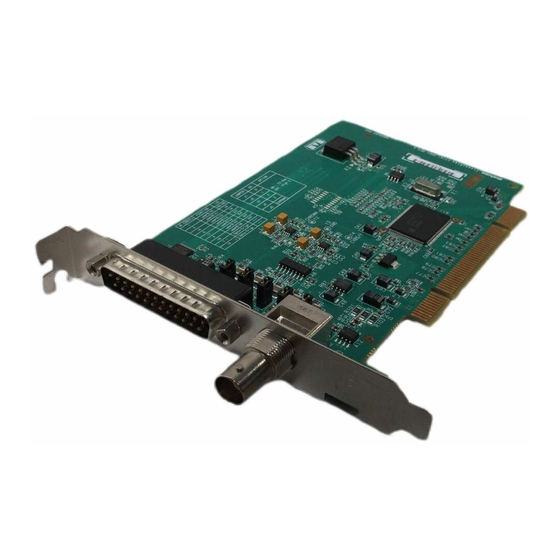
6 Chapter 1: Introduction Matrox CronosPlus Matrox CronosPlus is a standard monochrome and composite color analog frame grabber for extremely cost-sensitive imaging applications. This board is available in a PCI form factor and can acquire different types of standard video formats using its video decoder. -
Page 7: Data Transfer
Software Matrox CronosPlus has 3 TTL auxiliary input signals and 4 TTL auxiliary output signals, that can be used to transmit and receive application-specific user input and output, and one opto-isolated auxiliary signal, that can be used to trigger image acquisition. -
Page 8: Essentials To Get Started
• Microsoft Windows if using Matrox Imaging software (consult the documentation accompanying the software for specific supported environments and computer memory/storage requirements). • A DVD drive, and a hard disk or network drive on which to install the Matrox CronosPlus software. -
Page 9: Inspecting The Matrox Cronosplus Package
• The Matrox CronosPlus base board. Optional items You might have also ordered one or more of the following: • MIL or MIL-Lite. Matrox Intellicam is included with both of these software packages. • DB25-TO-5BNC/O cable, an 8-inch input cable with a 25-pin female DB-25 connector on one end and 5 BNCs and open-ended wires on the other end. -
Page 10: Installation Overview
2. Complete the software installation procedure as described in the documentation accompanying your software package. For information on using multiple Matrox CronosPlus boards, refer to Chapter 3: More information Using multiple Matrox CronosPlus boards. For in-depth hardware information, refer to Chapter 4: Hardware reference,... -
Page 11: Chapter 2: Hardware Installation
Chapter Hardware Chapter 2: installation This chapter explains how to install the Matrox CronosPlus hardware. -
Page 12: Installing Matrox Cronosplus
Matrox CronosPlus board. Five empty (32-bit) PCI slots are illustrated below: 3. If present, remove the blank metal plate located at the back of the selected slot. Keep the removed screw; you will need it to fasten the Matrox CronosPlus board. - Page 13 Installing Matrox CronosPlus 4. Carefully position Matrox CronosPlus in the selected PCI slot. 5. Once perfectly aligned with an empty slot, press the board firmly but carefully into the connector. 6. Anchor the board by replacing the screw that you removed.
-
Page 14: Connecting External Devices To Matrox Cronosplus
14 Chapter 2: Hardware installation 7. Replace the cover of your computer, and connect your video sources. For details, see the Connecting external devices to Matrox CronosPlus section, later in this chapter. 8. Turn on your computer. In some cases, when you boot your computer, Windows’ Plug-and-Play system will detect a new PCI board and you will be asked to assign a driver to it. - Page 15 Connecting external devices to Matrox CronosPlus The wires of the cable for video input are listed in the following table: W i r e l a b e l S i g n a l E x p e c t e d i n p u t...
- Page 16 16 Chapter 2: Hardware installation...
-
Page 17: Chapter 3: Using Multiple Matrox Cronosplus Boards
Chapter Using multiple Chapter 3: Matrox CronosPlus boards This chapter explains how to use multiple Matrox CronosPlus boards. -
Page 18: Multiple Board Installation
(refer to Chapter 2). In other words, place each additional board in an empty slot. Theoretically, you can have as many as 16 Matrox CronosPlus boards installed in your computer at one time; this number is, however, limited by the number of empty slots in your computer and, for simultaneous grabs, by the available bandwidth of your computer (discussed later in this chapter). - Page 19 PCI bandwidth of 35 Mbytes/sec or 42 Mbytes/sec, respectively, when transferring in RGBX (32-bit) mode. When grabbing from three or more Matrox CronosPlus boards simultaneously, you will have to reduce the image size to avoid reaching the upper limits of the...
- Page 20 20 Chapter 3: Using multiple Matrox CronosPlus boards...
-
Page 21: Chapter 4: Hardware Reference
Chapter Hardware reference Chapter 4: This chapter explains the architecture of the Matrox CronosPlus hardware, as well as the available features and modes. -
Page 22: Matrox Cronosplus Hardware Reference
Matrox CronosPlus hardware reference This chapter provides information on the architecture, operating modes, and supported features of Matrox CronosPlus. For a summary of the information given in this chapter and detailed specifications of connectors and pinouts, refer to Appendix B: Technical information of this manual. -
Page 23: Grab Features
Grab features Grab features The Matrox CronosPlus board is equipped with a video decoder chip that has an integrated PCI interface. The chip can grab RS-170 /CCIR monochrome video and composite (CVBS) and component (Y/C) video in NTSC /PAL format. -
Page 24: Low-Pass Filter
Low-pass filter The input low-pass filtering stage is used to limit high frequency noise and aliasing effects at the input of the decoder. The filters used on Matrox CronosPlus are 4th order Butterworth filters with a cut-off frequency of 8 MHz. -
Page 25: Auxiliary Signals
Auxiliary signals Auxiliary signals are non-video signals that can be used to synchronize with, react to, and/or cause external events. Matrox CronosPlus has three TTL auxiliary input signals, four TTL auxiliary output signals, and one opto-isolated auxiliary signal. The opto-isolated auxiliary input signal can be used to trigger image acquisition. -
Page 26: User Signals
26 Chapter 4: Hardware reference User signals Matrox CronosPlus has three TTL auxiliary input signals that can be used to receive application-specific user input and four TTL auxiliary output signals that can be used to transmit user output. If you want to start or stop an external event based on some calculation or analysis, you can manually set the state of any auxiliary output signal to high or low. -
Page 27: Pci Interface
PCI interface PCI interface Matrox CronosPlus has a 32-bit PCI bus interface, which is capable of a peak transfer rate of 132 Mbytes/sec, and operates at 33 MHz. Matrox CronosPlus uses an internal FIFO to buffer image data while waiting to access the PCI bus. - Page 28 28 Chapter 4: Hardware reference...
-
Page 29: Appendix A: Glossary
Appendix A: Glossary Appendix A: This appendix defines some of the specialized terms used in this Matrox CronosPlus document. -
Page 30: Glossary
30 Appendix A: Glossary Glossary • AGC Automatic Gain control. Used to keep the output signal of a circuit constant as the input signal amplitude varies. • Bandwidth A term describing the capacity to transfer data. Greater bandwidth is needed to sustain a higher transfer rate. - Page 31 Glossary • Grab To acquire an image from a camera. • Horizontal sync The part of a video signal that indicates the end of a line and the start of a new one. See also vertical sync. • Host In general, Host refers to the principal CPU in one’s computer. •...
- Page 32 32 Appendix A: Glossary • PLC Programmable Logic Controller. A device used to automate monitoring and control of industrial plants. It can be used as a stand-alone device or in conjunction with data acquisition. • Progressive scanning Describes a transfer of data in which the lines of the source input device are written sequentially into the destination buffer.
-
Page 33: Appendix B: Technical Information
Appendix B: Technical Appendix B: information This appendix contains information that might be useful when installing your Matrox CronosPlus board. -
Page 34: Technical Information
- An available conventional 3.3 V or 5 V PCI expansion slot (bus-master capable). - A computer with a relatively up-to-date PCI chipset. The list of platforms that are known to be compatible with Matrox CronosPlus are available on the Matrox website, under the board’s PC compatibility list. -
Page 35: Electrical Specifications
Electrical specifications Electrical specifications O p e r a t i n g v o l t a g e a n d c u r r e n t ( t y p i c a l ) V o l t a g e C u r r e n t P o w e r ±... -
Page 36: Environmental Specifications
• Max. altitude for operation: 3000 meters. • Max. altitude for transport: 12000 meters. • Operating humidity: 20 - 80% relative humidity (non-condensing). Board connectors The Matrox CronosPlus board has a BNC video input connector and a DB-25 video input connector on its bracket. -
Page 37: Bnc Connector
Board connectors BNC connector The BNC connector is used to receive CVBS video input 0 or the Y component of Y/C video input. Its pin assignment is as follows: D e s c r i p t i o n P i n S i g n a l I / O... -
Page 38: Video Input Connector
38 Appendix B: Technical information Video input connector The video input connector is a standard D-subminiature 25-pin (DB-25) male connector that is located on the module’s bracket. The connector is used to receive video input, and transmit or receive auxiliary signals (trigger input or user input/output). - Page 39 Board connectors To build your own cable, parts can be purchased from: M a n u f a c t u r e r A m p h e n o l C o n n e c t o r P / N E D - B - 2 5 - S B a c k s h e l l P / N 1 7 - 1 7 2 6 - 2...
- Page 40 40 Appendix B: Technical information...
-
Page 41: Index
Index low-pass filter 24 Matrox CronosPlus package automatic gain control 24 optional items 9 standard package 9 Matrox Inspector 8 Matrox Intellicam 8 cameras MIL 7 number of cameras per board 18 MIL-Lite 8 conventions 10 multiple boards 18 PCI bandwidth 18... -
Page 43: Regulatory Compliance
Telephone: (514) 822-6000 (x2026) • Attention: Conformity Group Declaration The Matrox hardware products supported by this guide comply with Part 15 of the FCC Rules. Operation is subject to the following two conditions: (1) these devices may not cause harmful interference, and (2) these devices must accept any interference received, including interference that may cause undesired operation. - Page 44 (English) Industry Canada Compliance Statement Remark for the Matrox hardware products supported by this guide These digital devices do not exceed the Class B limits for radio noise emission from digital apparatus devices set out in the Radio Interference Regulation of Industry Canada.
- Page 45 (Italiano) Informazioni per gli utenti europei – Dichiarazione di conformità Nota per i prodotti hardware Matrox supportati da questa guida Questi dispositivi sono conformi alla direttiva CEE 89/336/EEC relativamente ai dispositivi digitali di Classe B. Sono stati provati e sono risultati conformi alle norme EN55022/CISPR22 e EN55024/CISPR24.
- Page 46 Bitte wenden Sie sich an dem Matrox-Website (www.matrox.com/environment/weee) für Recycling Informationen. (Italiano) Informazioni per gli utenti europei – Direttiva sui rifiuti di apparecchiature elettriche ed elettroniche (RAEE) Si prega di riferirsi al sito Web Matrox (www.matrox.com/environment/weee) per le informazioni di riciclaggio.
-
Page 47: Limited Warranty
Limited Warranty Refer to the warranty statement that came with your product.
Need help?
Do you have a question about the CronosPlus and is the answer not in the manual?
Questions and answers