
Related Manuals for Matrox 4Sight X


Summary of Contents for Matrox 4Sight X
- Page 1 Matrox 4Sight X Installation and Hardware Reference Manual no. Y11112-101-0201 August 25, 2010...
- Page 2 © Copyright Matrox Electronic Systems Ltd., 2008-2009. All rights reserved. Limitation of Liabilities: In no event will Matrox Electronic Systems Ltd. or its suppliers be liable for any indirect, special, incidental, economic, cover or consequential damages arising out of the use of or inability to use the product, user...
-
Page 3: Table Of Contents
Inspecting the Matrox 4Sight X package ........ - Page 4 Overview ............60 Removing the Matrox 4Sight X chassis cover ....... 62 Connecting a hard disk or CD/DVD drive .
- Page 5 Matrox 4Sight X unit ........
- Page 6 Fan ............100 Chassis for the Matrox 4Sight XB unit ......101 Chassis for the PCI/104-Express Matrox 4Sight X unit.
- Page 7 The Selection window......... 111 The Item Specific Help window .
- Page 8 Matrox Comment submenu ........
- Page 9 Matrox Nexis for PCI-104 ........
- Page 10 Appendix C: Hardware glossary ......193 Glossary ............194 Index Regulatory Compliance Product support...
-
Page 11: Using This Manual
For users who have purchased the motherboard-only version of Matrox 4Sight X, and need to install it into a custom chassis, the specifications of such a chassis, fan, and power supply can also be found in this reference. - Page 12 To do so, you should first complete and submit the online Technical Support Request Form, accessible from the above-mentioned web page. Once you have submitted the information, a Matrox support agent will contact you shortly thereafter by email or phone, depending on the problem.
-
Page 13: Part 1: Operating The Matrox 4Sight X Unit
Part 1: Operating the Matrox 4Sight X unit... -
Page 15: Chapter 1: Before You Begin
Chapter Before you begin This chapter introduces you to the key features of Matrox 4Sight X. -
Page 16: Overview
- The motherboard-only version. The motherboard-only version provides one Matrox 4Sight X motherboard. This version is sold without the chassis, and is not bundled with SO-DIMM memory modules, a mass storage device, a fan,... -
Page 17: Matrox 4Sight Xb Unit
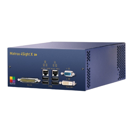
PCIe boards), and any optional Matrox PCIe board(s), all of which are encased within a metal chassis. Naming convention This manual refers to both types of units as Matrox 4Sight X. When necessary, it distinguishes between them using their full name. Operating system The Matrox 4Sight X unit supports the following operating systems: •... - Page 18 GigE Ethernet Analog video output connector connectors DVI-D connector Four USB 2.0/1.1 connectors (underneath) (underneath) Front panel external connectors and components Note that, for the Matrox 4Sight XB unit, a riser board is connected to the PCIe connector on the motherboard.
-
Page 19: Motherboard
BIOS, PCI/PCIe and IEEE 1394b connectivity, and general purpose I/O (auxiliary I/O, serial I/O, audio I/O, and USB). • Processing. The Matrox 4Sight X motherboard features either an Intel Celeron 550 2.0 GHz processor or an Intel Core 2 Duo T7500 2.2 GHz processor , covered by a heat sink. - Page 20 20 Chapter 1: Before you begin • PCI and PCIe connectors. The Matrox 4Sight X motherboard has connectors that provide a PCI interface and an x4 PCIe interface. Together, these two interfaces allow you to connect boards to your unit; the type and number depends on the type of your Matrox 4Sight X.
-
Page 21: Mass Storage
• Random access memory (RAM). The Matrox 4Sight X motherboard has two 200-pin SO-DIMM slots, each slot supporting a SO-DIMM memory module up to 2 Gbytes in size. When the Matrox 4Sight X unit is purchased with memory modules, the unit will have two identical memory modules installed, and total memory will be 1 Gbyte, 2 Gbytes, or 4 Gbytes, depending on what was ordered. -
Page 22: Optional Boards
Boards for the Matrox 4Sight XB unit The Matrox 4Sight XB unit is equipped with a riser board (attached to the PCIe connector on the motherboard) that allows you to connect Matrox or third-party full-height, half-length x1, x4, or x8 PCIe boards. - Page 23 The board is available with either: • An acquisition section and a JPEG2000 accelerator. • An acquisition section only. ❖ Note that Matrox Morphis Dual for PCI-104 does not include an I/O controller (so it does not support user-defined signals). Matrox Meteor-II /Multi-Channel for PCI-104 Matrox Meteor-II /Multi-Channel for PCI-104 is a frame grabber that captures monochrome or component RGB analog video.
-
Page 24: Inspecting The Matrox 4Sight X Package
Inspecting the Matrox 4Sight X package The following tables list standard and optional items that can be included in the Matrox 4Sight X package. If anything is missing or damaged, contact Matrox for assistance. You will receive different items depending on whether you ordered: •... - Page 25 Instructions to receive the A sheet that directs you to the Matrox website to download this manual. This manual can assist you with the setup of the Matrox 4Sight X unit and the Matrox 4Sight X installation connection of peripheral and internal devices.
-
Page 26: Motherboard-Only Version
A sheet that directs you to the Matrox website to download this manual. This manual: Matrox 4Sight X manual can assist you with the setup of the Matrox 4Sight X unit and the connection of peripheral and internal devices. installation and hardware reference 1. -
Page 27: Light Emitting Diodes (Leds)
Light emitting diodes (LEDs) Light emitting diodes (LEDs) There are a total of eight clearly-labelled LEDs on a Matrox 4Sight X unit. The Matrox 4Sight XB unit is taller On LED Activity/Link LED GigE LED User LED Diagnostics LED HDD LED... -
Page 28: Back Panel Leds
• HDD LED (bottom). The hard disk drive LED turns green when the hard disk is working. Handling precautions The Matrox 4Sight X motherboard is sensitive to static electricity and surges. To avoid damaging the motherboard, follow these precautions. The following precautions apply to both the integrated and motherboard-only... -
Page 29: Turning Off And Restarting The Unit
Turning off and restarting the unit Turning off the integrated-unit version of Matrox 4Sight X To turn off the integrated-unit version of Matrox 4Sight X, push and hold the power button. While the power button is being pressed, the unit will shut off. - Page 30 30 Chapter 1: Before you begin...
-
Page 31: Chapter 2: Connecting Peripherals To The Unit
Chapter Connecting peripherals to the unit This chapter is geared to users who are ready to connect various peripherals to their unit. -
Page 32: Overview
32 Chapter 2: Connecting peripherals to the unit Overview This chapter describes how to connect various devices to the Matrox 4Sight X unit. Front panel and back pane external connectors Faceplate with connectors of PCI-104 or PCI/104-Express board(s) installed in PCI/104-Express Matrox 4Sight X unit... -
Page 33: Connecting Video Output Display Devices
• A stereo audio device. Connecting video output display devices You can connect up to two video output display devices to the Matrox 4Sight X unit: • You can connect a high-resolution analog display device (such as an analog monitor or an analog flat panel) to the analog video output connector. -
Page 34: Connecting A High-Resolution Analog Display Device
Connecting a high-resolution analog display device To connect a high-resolution analog display device to the analog video output connector on the Matrox 4Sight X unit, do the following: 1. If your device has a standard HD-15 connector, use a standard HD-15 to HD-15 cable, and skip the remaining steps. -
Page 35: Connecting A High-Resolution Digital Display Device
USB connectors six USB connectors. Four USB connectors are located on the front panel of the Matrox 4Sight X unit, and two USB connectors are contained inside the unit (on the motherboard). The USB connectors are USB 2.0 and 1.1 compatible. -
Page 36: Networking Connections
36 Chapter 2: Connecting peripherals to the unit Networking connections You can connect Matrox 4Sight X to your local area network (LAN). To do so, connect a network cable to one of the two GigE Ethernet connectors, located on the front panel of the chassis. - Page 37 Networking connections To connect the Matrox 4Sight X unit in a peer-to-peer 100BaseT or 10BaseT Peer-to-peer communication communication configuration, you will have to use a custom-made crossover network cable to connect the unit and the computer. Peer-to-peer connection for Matrox 4Sight X...
-
Page 38: Connecting Video Input Devices
38 Chapter 2: Connecting peripherals to the unit Connecting video input devices If you have purchased the Matrox 4Sight X unit with a Matrox frame grabber, the board comes factory installed in the unit and has external connectors located on a faceplate on the back panel of the Matrox 4Sight X unit. - Page 39 Connecting video input devices ❖ Note that these boards, and their corresponding external faceplates (shown in the following illustration), cannot be installed in the Matrox 4Sight XB unit. Faceplate connectors for Matrox boards installed in the PCI/104-Express Matrox 4Sight X unit...
- Page 40 To connect video sources to the Camera Link connectors, use standard Camera Cable Link cables with a 26-pin high-density male mini Camera Link connector (HDR or SDR) at one end. For Matrox Solios eM-CLB, you should use PoCL Camera Link cables (HDR or SDR) when connecting to PoCL video sources.
- Page 41 Otherwise, the cables can have different propagation delays. Use the Camera Link cable from the camera manufacturer or from Components Express inc. Note that this cable is not available from Matrox. Manufacturer: Components Express inc.
- Page 42 Matrox Nexis for PCI-104 Extender board Faceplate Auxiliary I/O connector Remote head connectors Use the cable that is included with the Matrox Nexis camera head to connect to Cable the remote head connectors.
- Page 43 Dual for PCI-104 board. The pins of the Matrox HD-44M-18BNC cable are wired differently. The Matrox HD-44M-18BNC+ input cable is a 3-foot cable with a 44-pin male connector at one end and eighteen BNC female type connectors at the other end.
- Page 44 44 Chapter 2: Connecting peripherals to the unit The BNC connectors for the Matrox HD-44M-18BNC+ cable are labelled below. BNC label Signal Video device to connect and software channel number (MdigChannel()) CH-0 VID_IN0 A CVBS video source (channel 0), or the Y component of a Y/C video source (channel 0).
- Page 45 Extender board Matrox Meteor-II /Multi-Channel for PCI-104 Use the Matrox DBHD44-TO-8BNC cable to interface video sources to the Cable Matrox Meteor-II /Multi-Channel frame grabber. This cable has a 44-pin connector on one side, and eight BNC connectors on the other. It supports up to...
- Page 46 1. Connect the BNC wires to each RGB camera using the information from the above table. 2. Attach the 44-pin connector to the video input connector of Matrox 4Sight X. You can also use a Matrox DH44-TO-8BNC/O cable if you need to connect to...
-
Page 47: Connecting Devices To The Serial Port
RS-485. For details on the connector pinout of each interface, refer to Appendix B: Technical reference. For more information on the two serial ports, refer to the Serial ports section, in Chapter 5: Matrox 4Sight X hardware reference. -
Page 48: Connecting Devices To The Auxiliary I/O Interface
100 mA Power Connected Output signal source external fuse +24 V device Matrox 4Sight X Each of the sink drivers of Matrox 4Sight X uses a 100 mA fuse to protect it from connected external devices. - Page 49 Connecting devices to the auxiliary I/O interface When the output signal is on, the circuit is grounded and the current flows from the connected device to Matrox 4Sight X; when the signal is off, the circuit is open. State of the output signal...
- Page 50 To connect Matrox 4Sight X to an NPN-compatible PLC device, the ground of Matrox 4Sight X must be connected directly to the NPN-compatible PLC device’s ground. In addition, an output signal of Matrox 4Sight X must be connected to the device’s sinking input. You should connect the ground of the NPN-compatible PLC device and the ground of Matrox 4Sight X to a common ground.
- Page 51 The external resistor pull-up assures that when the output is disabled (off ), the external resistor will pull-up the PLC input to a positive voltage (+V). This creates an inversion, with the PLC input "on" when the Matrox 4Sight X output is "off", and vice-versa.
- Page 52 In addition, you should connect the positive side (cathode) of the load to a +24 V power supply. When the Matrox 4Sight X output signal is enabled, the negative side of the load is reduced to 0 V, and 24 V appears across the circuit.
- Page 53 Connecting devices to the auxiliary I/O interface Connecting to a strobe device To connect Matrox 4Sight X to a strobe device, connect the Matrox 4Sight X output signal directly to the strobe device. The Ring LED activates when the connected Matrox 4Sight X output signal is enabled (on).
- Page 54 54 Chapter 2: Connecting peripherals to the unit Connecting to a TTL device To connect Matrox 4Sight X to a TTL device, you must first connect an external resistor pull-up between them. The external resistor pull-up is needed because TTL devices expect to be connected to a device that can provide power (a sourcing device) and Matrox 4Sight X is a sinking device.
-
Page 55: Connecting External Devices To The Input Signals
Each of the input signals of Matrox 4Sight X is TTL-compatible. The Matrox 4Sight X input signals will be enabled (on) when the voltage applied is greater than 2 V. The Matrox 4Sight X input signals will be disabled (off ) when voltage is lower than 0.8 V. - Page 56 56 Chapter 2: Connecting peripherals to the unit...
-
Page 57: Part 2: Dealing With The Motherboard
Part 2: Dealing with the motherboard... -
Page 59: Chapter 3: Adding Devices To The Matrox 4Sight X Motherboard
Chapter Adding devices to the Matrox 4Sight X motherboard This chapter deals with additions that can be made to the Matrox 4Sight X motherboard. -
Page 60: Overview
SO-DIMM memory modules, fans, and mass storage devices. The unit also has connectors for frame grabbers: • The Matrox 4Sight XB unit has a riser board attached to the PCIe connector on the motherboard; you can connect Matrox or third-party full-height, half-length x1, x4, or x8 PCIe boards to the riser board. - Page 61 Overview The following diagram provides a reference to motherboard connectors. Internal (motherboard) PCI-104 connector connectors PCIe/104 connector SO-DIMM slots USB header Fan power supplies USB port 7-pin SATA connector USB port for a hard disk drive Hard disk drive power supply 7-pin SATA connector Hard disk drive power supply for a hard disk drive...
-
Page 62: Removing The Matrox 4Sight X Chassis Cover
Matrox 4Sight XB unit. Important 1. Unplug the Matrox 4Sight X power cord. 2. Remove the appropriate screws and nuts from the Matrox 4Sight X unit’s front panel (see the following illustration). Front panel... - Page 63 Removing the Matrox 4Sight X chassis cover 3. With the unit laid flat, face the back panel, place your hands on top of the chassis, and slowly slide the cover so that the cover and front panel (which are attached) separate from the rest of the unit.
- Page 64 64 Chapter 3: Adding devices to the Matrox 4Sight X motherboard Warning Once you have removed the cover and exposed the motherboard, do not touch the heat sinks (see illustration below) while the unit is running, or soon after the unit has been turned off;...
-
Page 65: Connecting A Hard Disk Or Cd/Dvd Drive
Connecting a hard disk or CD/DVD drive Connecting a hard disk or CD/DVD drive The Matrox 4Sight X motherboard provides two SATA 7-pin connectors, and corresponding power supply connectors, allowing you to connect one or two mass storage devices such as hard disk drives. The locations of the two SATA connectors, and their corresponding power supply connectors, on the Matrox 4Sight X motherboard are shown in the diagram below. -
Page 66: Drive Assignments
The Matrox 4Sight X motherboard provides two 4-pin power supplies for cooling fans. For more information on positioning the fan(s) in the chassis, see the Custom fan section, in Chapter 4: Installing the Matrox 4Sight X motherboard in a custom chassis. -
Page 67: Installing Full-Height, Half-Length Pcie Boards In The Matrox 4Sight Xb Unit
❖ Note that, instead of opening the side door, you can remove the chassis cover and insert/remove the board, but this takes more time. If you want to remove the chassis cover, see Removing the Matrox 4Sight X chassis cover section, earlier in this chapter. Opening the side door of the Matrox 4Sight XB chassis To open the side door of the chassis, remove the screws on the door;... -
Page 68: Installing Full-Height, Half-Length Pcie Boards
You can connect one or two full-height, half-length x1, x4, or x8 PCIe boards to the internal riser board of the Matrox 4Sight XB unit. To do so, after opening the side door of the unit, follow the steps below. - Page 69 Installing full-height, half-length PCIe boards in the Matrox 4Sight XB unit 2. Press the board firmly but carefully into the PCIe connector on the riser board, while inserting the tab of the board faceplate into the groove at the bottom of the card cage.
-
Page 70: Other Considerations
70 Chapter 3: Adding devices to the Matrox 4Sight X motherboard Other considerations The following critical points should be considered when installing full-height, half-length PCIe boards in your Matrox 4Sight XB unit: • You can install two full-height, half-length PCIe boards and simultaneously grab images from video sources attached to the different boards. -
Page 71: Installing Pci-104 And/Or Pci/104-Express Boards In The Pci/104-Express Matrox 4Sight X Unit
Installing PCI-104 and/or PCI/104-Express boards in the PCI/104-Express Matrox 4Sight X unit Installing PCI-104 and/or PCI/104-Express boards in the PCI/104-Express Matrox 4Sight X unit You can connect a total of three PCI-104 or PCI/104-Express boards to the motherboard of the PCI/104-Express Matrox 4Sight X unit. The boards are connected in a stack-through configuration, as shown below. -
Page 72: Number Of Boards
Third-party boards Three (3) boards 1. You cannot connect Matrox and third-party PCI/104-Express boards in the same unit. You can either install one Matrox Solios eM-CLB/eM-CLF for PCI/104-Express board, or you can install third-party PCI/104-Express board(s), but not both. 2. You can only install one third-party x4 PCI/104-Express board. If you need to install more than one third-party PCI/104-Express board, the boards must have x1 PCIe interfaces, and must support lane shifting and stack-up configurations, as defined in the PCI/104-Express standards. - Page 73 The rotary switch selects a specific PCI signal for each specific board. ❖ Note that the Matrox Solios eM-CL board does not have a rotary switch, therefore this section does not apply to this board.
- Page 74 74 Chapter 3: Adding devices to the Matrox 4Sight X motherboard It is recommended that you configure the first module installed (the module closest to the motherboard) to 0, the second to 1, and so on. If you are installing...
- Page 75 Warning • On the PCI connector of the PCI/104-Express Matrox 4Sight X unit, the voltage I/O pins are set to 3.3 V. Therefore, the PCI/104-Express Matrox 4Sight X unit does not support all PCI-104 boards. Use only PCI-104 boards with 3.3 V...
-
Page 76: Installing Or Removing Ram
The Matrox 4Sight X motherboard features two 200-pin SO-DIMM slots in which you can install random access memory (RAM) modules. Each slot can support one DDR2 SDRAM module up to 2 Gbytes in size. Matrox 4Sight X supports 1.8 V, unbuffered, PC2-5300-compliant DDR2 SDRAM. Contact Matrox for a list of supported modules. -
Page 77: Installing Memory
2. Lift the module out of the slot. Adjusting the new memory settings If the Matrox Imaging Library (MIL) or one of its derivatives is installed on the unit, you must adjust the unit’s new memory settings using MilConfig (the MIL Configuration utility). - Page 78 78 Chapter 3: Adding devices to the Matrox 4Sight X motherboard...
-
Page 79: Chapter 4: Installing The Matrox 4Sight X Motherboard In A Custom Chassis
Chapter Installing the Matrox 4Sight X motherboard in a custom chassis This chapter provides some guidelines for installing the Matrox 4Sight X motherboard in a custom chassis. -
Page 80: Overview
Handling precautions section, found in Chapter 1: Before you begin. Custom chassis The Matrox 4Sight X motherboard complies with the EBX form factor, 8” x 5¾” (20.32 cm x 14.61 cm). Make sure your custom chassis provides clearance for all motherboard components, particularly the DDR2 SDRAM module(s) and any PCI-104 or PCI/104-Express boards. -
Page 81: Custom Fan
Custom fan Custom fan You can use any fan that provides at least 18 cubic feet/minute (0.5 m /minute) of air flow through the large heat sink. Due to the large heat sink’s convoluted fins, the fan must be placed on the left or right side of the large heat sink (see illustration below). -
Page 82: Custom Power Supply
82 Chapter 4: Installing the Matrox 4Sight X motherboard in a custom chassis Custom power supply The power connector on the stand-alone Matrox 4Sight X motherboard is a 4-pin locking connector. Pin 1 Pin 2 Pin 3 Pin 4 Rear of motherboard Voltage requirements for each pin are given below. -
Page 83: Part 3: Reference Material For All Users
Part 3: Reference material for all users... -
Page 85: Chapter 5: Matrox 4Sight X Hardware Reference
Chapter Matrox 4Sight X hardware reference This chapter provides hardware descriptions of Matrox 4Sight X components. -
Page 86: Overview
Appendix B: Technical reference. Motherboard The Matrox 4Sight X EBX motherboard (see following block diagram) integrates processing, display, storage, networking, and I/O functionality. EBX is a standard form factor with a small footprint: 8” x 5¾” (20.32 cm x 14.61 cm). - Page 87 Only the PCI/104-Express Matrox 4Sight X unit supports PCI-104 and PCI/104-Express boards. The Matrox 4Sight XB unit does not support these boards. You can attach full-height, half-length PCIe boards to this PCIe connector (via a riser board). Only the Matrox 4Sight XB unit supports full-height, half-length PCIe boards.
-
Page 88: Processing
88 Chapter 5: Matrox 4Sight X hardware reference Processing The Matrox 4Sight X motherboard supports either the Intel Celeron 550 Processor processor running at 2.0 GHz, or the Intel Core 2 Duo T7500 processor running at 2.2 GHz. The chipset consists of the Intel GME965 graphics and memory controller hub Chipset (GMCH) and the Intel ICH8 I/O controller hub (ICH). -
Page 89: Processor Technologies
Processing • Power management features. • The Intel ICH8 interfaces with the BIOS via the serial peripheral interface (SPI) bus. The Intel ICH8 also interfaces with the GME965 via the direct media interface (DMI) at speeds up to 1.0 Gbytes/sec. In addition, the Intel ICH8 interfaces with the Super I/O controller chip via the low-pin count (LPC) bus. -
Page 90: Ram
The Intel GME965 GMCH chip uses up to 384 Mbytes of computer memory to store display data. Encoder Matrox 4Sight X provides a video encoder driven by one of the graphics controllers of the GME965 GMCH chip. This encoder uses transition minimized differential signaling (TMDS) through the digital visual interface (DVI-D). -
Page 91: Bios
The basic input/output system (BIOS) is the interface between the operating system and the hardware. Its data, crucial to the proper functioning of the hardware, is stored in a flash memory device which sits on the Matrox 4Sight X motherboard. -
Page 92: I/O Interfaces
USB-connected CD/DVD drive, or a printer, as well as low-speed peripherals such as a keyboard or mouse. Matrox 4Sight X is also equipped with a USB header, allowing you to connect a 10-pin USB flash module or two additional 4-pin USB devices. -
Page 93: Serial Ports
I/O interfaces Serial ports Matrox 4Sight X integrates two serial ports, the driver and the receiver of which are always enabled. Each interface is controlled by a Universal Asynchronous Receiver-Transmitter (UART) device, which converts serial data into parallel data when receiving information. Conversely, when transmitting information, the UART converts parallel data to serial data. - Page 94 94 Chapter 5: Matrox 4Sight X hardware reference Connecting the serial port to a multidrop network You can use either serial port to connect the Matrox 4Sight X unit to a multidrop network. This is a convenient means to connect the unit to multiple devices that are already connected to each other through this network.
- Page 95 Matrox 4Sight X does not support. (not supported) Note that because the driver and receiver for the Matrox 4Sight X serial port are always enabled, the unit cannot be connected to a typical RS-485 two-wire multidrop network shown below.
-
Page 96: Networking Interfaces
96 Chapter 5: Matrox 4Sight X hardware reference Networking interfaces The networking capabilities of Matrox 4Sight X are met by two GigE Ethernet networking interfaces that support the 10/100/1000BaseT Ethernet standards. A standard 10/100/1000BaseT Ethernet controller is built into the Intel ICH8 chip, providing high transfer rates to and from memory. -
Page 97: Pci And Pcie Interfaces
Matrox 4Sight X. Matrox 4Sight XB unit The PCIe interface of the Matrox 4Sight XB unit is extended using a riser board. The riser board allows you to install one or two Matrox (or third-party) full-height, half-length x1, x4, or x8 PCIe boards. The connectors on the riser board are x8 PCIe connectors supporting x1 or x4 electrical connections. -
Page 98: 1394B Interfaces
98 Chapter 5: Matrox 4Sight X hardware reference PCI/104-Express Matrox 4Sight X unit The PCI and PCIe interfaces of the PCI/104-Express Matrox 4Sight X unit allow you to install: - Up to three Matrox (or third-party) frame grabbers for PCI-104. -
Page 99: Audio Interface
Auxiliary I/O interface Matrox 4Sight X can send up to 16 independent sink driver output signals, and receive up to 16 independent input signals, to and from external devices connected to the auxiliary I/O interface. These signals can be connected to/from TTL and non-TTL devices (up to 24 V). -
Page 100: Power Supply, Fan, And Chassis
Refer to Chapter 4: Installing the Matrox 4Sight X motherboard in a custom chassis for details on the specifications of these components. Note that the Matrox 4Sight XB unit is only available in the integrated-unit version. -
Page 101: Chassis For The Matrox 4Sight Xb Unit
Power supply, fan, and chassis Chassis for the Matrox 4Sight XB unit The Matrox 4Sight XB chassis encloses the Matrox 4Sight X motherboard, a riser board, one or two full-height half-length PCIe boards, one or two 2.5 inch storage devices (such as hard disk drives or flash disk drives), two SO-DIMM memory modules, and a fan. -
Page 102: Chassis For The Pci/104-Express Matrox 4Sight X Unit
Note that you should use model #6-32 UNC screws (or screws of similar length and specifications) for mounting the Matrox 4Sight X unit to other equipment. The recommended length of the screws is 1/8" (0.125") or 3.2 mm (0.32 cm). -
Page 103: Power Management And Temperature Control
CPU’s demand for processing power. This results in decreased average power consumption and decreased average heat production. For more information on configuring ACPI and EIST for the Matrox 4Sight X unit, refer to Appendix A: BIOS reference. - Page 104 104 Chapter 5: Matrox 4Sight X hardware reference...
-
Page 105: Part 4: Appendices
Part 4: Appendices... -
Page 107: Appendix A: Bios Reference
Appendix A: BIOS reference This appendix describes the BIOS Setup utility. It also lists BIOS messages. -
Page 108: Overview
It also explains the different messages displayed by the BIOS during the course of the unit’s operation. ❖ Note that the Matrox 4Sight X unit uses a BIOS written by American Megatrends Inc. (AMIBIOS). Some of the menu items are not applicable to the supported operating systems of the Matrox 4Sight X unit. -
Page 109: The Bios Setup Utility
Entering the Setup utility To enter the Setup utility, turn on Matrox 4Sight X and press the Delete key during power-up self-test (POST). You only have a few moments to press this key before the boot-up process continues. -
Page 110: The Menu Bar
110 Appendix A: BIOS reference The Menu bar The Menu bar displays the following options: Menu Bar Options Description Main Configures basic computer properties. Advanced Configures advanced computer properties. PCIPnP Configures Plug and Play computer properties. Boot Configures various boot-up properties. Security Configures access to the BIOS Setup utility. -
Page 111: The Selection Window
The BIOS Setup utility The Selection window When a menu is selected, its name will appear highlighted in the menu bar and its menu items will be displayed with blue text in the Selection window. Within each menu, you can use the Up and Down keys to select the different items of the menu. -
Page 112: The Item Specific Help Window
112 Appendix A: BIOS reference The Item Specific Help window The Item Specific Help window provides a description of the selected menu item (the menu item in white), and in less obvious cases provides an explanation of the different settings of this item. Item Specific Help window This window provides a description of the menu... -
Page 113: Main Menu
Main menu Main menu This section describes all the items of the Main menu. Refer to the section entitled The Legend window for guidelines on navigating within this menu. BIOS SETUP UTILITY Main Advanced PCIPnP Boot Security Chipset Information Exit System Overview Use [ENTER], [TAB] or [SHIFT-TAB] to... - Page 114 This item reports the amount of memory (also referred to as random access memory, or RAM) that is available to the Matrox 4Sight X unit. System Memory Size = (Total RAM of SO-DIMM memory modules installed in unit) - (memory allocated to the graphics controller).
-
Page 115: Advanced Menu
Advanced menu Advanced menu This section describes all the items of the Advanced menu. Refer to the section entitled The Legend window for guidelines on navigating within this menu. BIOS SETUP UTILITY Main Advanced PCIPnP Boot Security Chipset Information Exit Advanced Settings Configure CPU. -
Page 116: Cpu Configuration Submenu
This allows one Disabled computer to function with multiple "virtual" operating systems, and isolate different computing activities into Enabled* separate partitions. You will need to reboot your Matrox 4Sight X unit for the changes to this item to take effect. ❖... - Page 117 Advanced menu Item Meaning Options Execute-Disable Bit Capability This item allows you to enable or disable the execute-disable bit capability of the CPU. The execute-disable bit capability of the CPU provides enhanced virus protection. This capability allows memory to be marked as Disabled executable or non-executable, allowing the CPU to raise an error to the operating system if malicious code Enabled*...
-
Page 118: Ide Configuration Submenu
(that is, the operating system calls the BIOS to enable hard disk access). This is true for DOS, but not for Enabled (don’t select) Microsoft Windows XP or Vista. Therefore, for the supported operating system of Matrox 4Sight X, you must choose Disabled. - Page 119 Advanced menu Primary IDE Slave and Secondary IDE Slave sub-submenus These sub-submenus do not apply to your Matrox 4Sight X unit. Primary IDE Master and Secondary IDE Master sub-submenus These sub-submenus describe the mass storage devices that are connected to the 7-pin SATA connectors on the motherboard.
- Page 120 Auto* Matrox 4Sight X uses hard disk drives that support LBA mode, so it is recommended to set this item to Auto. By selecting Disabled, LBA mode will be disabled on the device.
-
Page 121: Superio Configuration Submenu
Advanced menu SuperIO Configuration submenu The SuperIO Configuration submenu allows you to configure options of the Super I/O Controller chip on the motherboard. This chip controls the serial ports. Item Meaning Options Serial Port 1 Address This item allows you to set the base address of the RS-232 serial por t (top serial port). By selecting Disabled, the serial port is unavailable for use. -
Page 122: Acpi Configuration Submenu
By selecting Yes, the BIOS of the graphics controller will be initialized when resuming from the S3 (STR) state. Note that, with the supported operating systems for Matrox 4Sight X (these operating systems are listed in the Operating system section, in Chapter 1: Before you begin), this item is not supported. In this case, set... - Page 123 Advanced menu Advanced ACPI Configuration sub-submenu The Advanced ACPI Configuration sub-submenu allows you to configure advanced options of the ACPI. Item Meaning Options ACPI Version Features This option allows you to select the version of ACPI that the BIOS will report to the operating system. Select the ACPI features that the BIOS will support (features of ACPI 1.0, ACPI 2.0, or ACPI 3.0).
-
Page 124: Ahci Configuration Submenu
124 Appendix A: BIOS reference AHCI Configuration submenu The AHCI Configuration submenu reports on the mass storage devices (connected to the two SATA ports) that have been auto-detected by the BIOS. This submenu also allows you to disable these devices. If you need to use this submenu, you must: - Set the ATA/IDE Configuration item to Enhanced in the IDE Configuration submenu. -
Page 125: Apm Configuration Submenu
Note that, although this item is called "PS/2", this item applies to any keyboard and mouse connected to the Monitor* Matrox 4Sight X unit. In the case of the Matrox 4Sight X unit, this item refers to the USB keyboard and USB mouse that can be connected to the internal or external USB por ts. -
Page 126: Event Log Configuration Submenu
Revision 1.1 was the original specification. MPS version 1.4 adds improved support of multiple PCI bus 1.4* configurations. Revision 1.4 also introduces suppor t for a secondary PCI bus without requiring a PCI bridge. For the Matrox 4Sight X unit, you must leave this setting at 1.4. -
Page 127: Pci Express Configuration Submenu
By selecting Disabled, the PCIe link power states are unavailable. By selecting Enabled, the PCIe link power Disabled* states are available. Enabled For Matrox 4Sight X, it is strongly recommended that you set this option to Disabled (default). ❖ SMBIOS Configuration submenu The SMBIOS Configuration submenu allows you to enable or disable system management BIOS (SMBIOS) SMI wrapper support for Plug ’n Play function... -
Page 128: Remote Access Configuration Submenu
Note that some operating systems might not work under this setting. ❖ Note that this item does not apply to the supported operating systems of the Matrox 4Sight X. Terminal Type This item allows you to set the type of the remote terminal that a user can use to access the unit remotely via the serial ports. -
Page 129: Usb Configuration Submenu
If using Microsoft Windows XP , you need to install Service Pack 2 (SP2) or greater to take advantage of all ❖ the features available in the Matrox 4Sight X unit and MIL. Hotplug USB FDD Support This item allows you to enable or disable hotplug support for USB floppy disk drives. Hotplug support allows you to remove or replace a USB floppy disk drive, after POST has run, without having to reboot the unit. - Page 130 130 Appendix A: BIOS reference USB Mass Storage Device Configuration sub-submenu The USB Mass Storage Device Configuration sub-submenu allows you to select the reset delay, and the emulation type, for each USB mass storage device connected to the unit. Item Meaning Options USB Mass Storage Reset Delay...
-
Page 131: Pcipnp Menu
PCIPnP menu PCIPnP menu This section describes all the items of the PCIPnP (PCI Plug and Play) menu. Refer to the section entitled The Legend window for guidelines on navigating within this menu. Warning Setting the items below to the wrong values can cause the unit to malfunction. - Page 132 By selecting Disabled, SATA devices will not use bus mastering when receiving or transferring data; the Host Disabled CPU will perform the copy. By selecting Enabled, SATA devices will use bus mastering when receiving or Enabled* transferring data. Note that this item does not apply to the supported operating systems of the Matrox 4Sight X. ❖...
- Page 133 PCI or PnP device. DMA Channel 7 For each DMA channel): Available* Reserved Reserved Memory Size This item allows you to reserve memory for ISA boards. Since Matrox 4Sight X does not have ISA connectors, this item must be set to Disabled. Disabled*...
-
Page 134: Boot Menu
134 Appendix A: BIOS reference Boot menu This section describes all the items of the Boot menu. Refer to the section entitled The Legend window for guidelines on navigating within this menu. BIOS SETUP UTILITY Main Advanced PCIPnP Boot Security Chipset Information Exit... -
Page 135: Boot Settings Configuration Submenu
By selecting Enabled, an IDE/SCSI device can trap interrupt 19 and boot the unit. This item will not apply for the Matrox 4Sight X unit in its typical configurations (a typical Matrox 4Sight X unit will not have an IDE/SCSI bootable device). -
Page 136: Boot Device Priority Submenu
136 Appendix A: BIOS reference Boot Device Priority submenu The Boot Device Priority submenu allows you to specify the boot order of the available boot device categories: removable drives, hard disk drives, and CD/DVD drives. For example, if the first boot device category is removable drives, the BIOS will try to load an operating system from the removable drives first, in the order that is listed in the Removable Drives submenu. -
Page 137: Security Menu
Security menu Security menu This section describes all the items of the Security menu. Refer to the section entitled The Legend window for guidelines on navigating within this menu. There are two types of passwords that can protect the BIOS Setup utility: the supervisor password and the user password. - Page 138 138 Appendix A: BIOS reference Item Meaning Options Supervisor Password This item reports the status of the supervisor password: installed or not installed. "Installed" means that a supervisor password has been established. Use the Change Supervisor Password item to create or change the supervisor password.
- Page 139 This item is only relevant with an operating system that calls the BIOS to access hard disks. Microsoft Windows operating systems do not call the BIOS to access hard disks; therefore, for the supported operating systems of Matrox 4Sight X, you must set this item to Disabled (default). Hard Disk Security This item reports which password is required to access the submenus of your connected hard disk.
-
Page 140: Chipset Menu
140 Appendix A: BIOS reference Chipset menu This section describes all the items of the Chipset menu. Refer to the section entitled The Legend window for guidelines on navigating within this menu. Warning Setting the items below to the wrong values can cause the unit to malfunction. BIOS SETUP UTILITY Advanced PCIPnP... -
Page 141: North Bridge Configuration Submenu
RAM for these devices. However, since you cannot install any boards in the 15 - 16 Mbytes Matrox 4Sight X unit that require a memory hole to be created in RAM, set this item to Disabled (default). Boots Graphic Adapter Priority This item allows you to select which display device will be your primary display device (the device that will display the BIOS messages and the Microsoft Windows logo upon startup). -
Page 142: South Bridge Configuration Submenu
Although the ICH8 chip provides 10 USB por ts, not all of these ports have a corresponding connector in the 8 USB Ports Matrox 4Sight X unit. There are four external USB connectors on the front panel of the unit, and two USB 10 USB Ports* connectors and a 10-pin USB header inside the unit (on the motherboard). - Page 143 PCIe Por t 3 For the Matrox 4Sight XB unit, a riser board is connected to the PCIe ports. All ports must be left to Auto. For each port: For the PCI/104-Express Matrox 4Sight X unit, when you connect three x1 PCI/104-Express boards, Port 0, Auto* (best option) Port 1, and Port 2 are used;...
-
Page 144: Information Menu
The Legend window for navigation guidelines. BIOS SETUP UTILITY Main Advanced PCIPnP Boot Security Chipset Information Exit Matrox Specific Information System Information System Information Customer Comment Matrox Comment Select Screen Select Item Change Option General Help Save and Exit Exit v02.61 (C)Copyright 1985-2006 American Megatrends, Inc. -
Page 145: System Information Submenu
These items report the initial versions of the GigE LAN EEPROMs (there are two separate GigE LAN Initial LAN 2 EEPROM Version EEPROMs on the motherboard). Model Identifier These items report the Matrox 4Sight X model identifier (order number), and the system serial number System Serial Number (assembly serial number of the integrated unit). BIOS Version These items report the current BIOS version and the build date. -
Page 146: Exit Menu
146 Appendix A: BIOS reference Exit menu This section describes all the items of the Exit menu. Refer to the section entitled The Legend window for navigation guidelines. BIOS SETUP UTILITY Main Advanced PCIPnP Boot Security Chipset Information Exit Exit Options Exit system setup after saving the Save Changes and Exit... - Page 147 Cancel, and press the Enter key to continue. You can also press the Esc key to return to the Exit menu. Important: The optimal defaults are designed for maximum performance (speed), but might not work best for all applications. In particular, don’t select this option if your Matrox 4Sight X unit is experiencing system configuration problems.
-
Page 148: Overriding The Device Sequence
148 Appendix A: BIOS reference Overriding the device sequence When you turn on the unit, the BIOS checks the boot-devices for an operating system, according to the specific sequence in the Boot menu. However, it is possible to override this sequence and have the BIOS check a device that you specify, regardless of its position in the Boot menu. - Page 149 Overriding the device sequence 2. Using the Up and Down arrow keys, select the device from which you will load the operating system. 3. When the device is selected, press the Enter key. This will override the existing boot sequence (saved in the BIOS Setup utility) for this boot only, and the operating system will be booted using the selected device.
-
Page 150: Bios Messages
150 Appendix A: BIOS reference BIOS messages When Matrox 4Sight X is booted, the BIOS performs a POST. Once all the tasks are completed, the BIOS will proceed to boot the operating system. If a task cannot be completed, POST will report an error to the BIOS. - Page 151 BIOS messages Type of error BIOS Message Explanation Memory Gate20 Error The BIOS is unable to properly control the motherboard’s Gate A20 function, which controls access to memory over 1 Mbyte. This might indicate a problem with the motherboard. Multi-Bit ECC Error This message will only occur on units using ECC-enabled memory modules.
- Page 152 152 Appendix A: BIOS reference Type of error BIOS Message Explanation Virus-related BootSector Write !! The BIOS has detected software attempting to write to a drive’s boot sector. This is flagged as possible virus activity. This message will only be displayed if Virus Detection is enabled in the BIOS Setup utility.
- Page 153 BIOS messages Type of error BIOS Message Explanation CMOS CMOS Date/Time Not Set The CMOS date and/or time are invalid. You can resolve this error by readjusting the time in the BIOS Setup utility. CMOS Battery Low The CMOS battery is low. This message usually indicates that the CMOS battery needs to be replaced.
- Page 154 154 Appendix A: BIOS reference...
-
Page 155: Appendix B: Technical Reference
Appendix B: Technical reference This appendix summarizes the key features of the Matrox 4Sight X unit. In addition, this appendix provides pinout descriptions for external and internal connectors of the Matrox 4Sight X unit. -
Page 156: Overview
• Internal connectors: - One PCI interface (the Matrox 4Sight XB unit does not use this interface). - One x4 PCIe interface (the Matrox 4Sight XB unit has a riser board attached to this interface). - Two 200-pin SO-DIMM slots. -
Page 157: Environmental Specifications
Two 200-pin SO-DIMM slots, each of which supports one PC2-5300, unbuffered DDR2 SDRAM SO-DIMM module, up to 2 Gbytes in size. Hard disk drive • Default storage capacity: 40 Gbytes (other capacities are available from Matrox). • A 2.5 inch platter. • Rotational speed: 5400 rpm. -
Page 158: Power Supply
• Length: 8.200" (20.828 cm), width: 7.250" (18.415 cm). • Height: - 4.690" (11.913 cm) for the Matrox 4Sight XB unit. - 3.302" (8.387 cm) for the PCI/104-Express Matrox 4Sight X unit. • Rated at 18 - 38 cubic feet/minute (0.5 - 1.07 m /minute), with operating... -
Page 159: Battery
• Diameter (max): 20 mm. Riser board • Available only for the Matrox 4Sight XB unit. • Three PCIe slots, whereby one slot is inactive. • Each PCIe slot is an x8 PCIe slot, with only x4 or x1 electrical connections. -
Page 160: Auxiliary I/O Interface Signal Characteristics
160 Appendix B: Technical reference Auxiliary I/O interface signal characteristics The auxiliary I/O interface signals of Matrox 4Sight X have the following characteristics: • Rise and fall time. Rise and fall time refers to the amount of time it takes a signal to rise to its peak, or fall back to a normal level. - Page 161 Auxiliary I/O interface • Pulse width. The pulse width is determined to be from the mid-point of the rise time to the mid-point of the fall time. Pulse width Mode Total voltage (Vcc) Current load (Icc) Minimum Input 100 msec 24 V 100 msec Output...
- Page 162 Mode Description Minimum Maximum Input Voltage range for Matrox 4Sight X unit to interpret voltage 2.4 V 24 V on auxiliary I/O interface (input ports) as a "1." Voltage range for Matrox 4Sight X unit to interpret voltage 0.8 V on auxiliary I/O interface (input ports) as a "0."...
-
Page 163: Pinout Descriptions Of Front Panel Connectors
Pinout descriptions of front panel connectors Pinout descriptions of front panel connectors The Matrox 4Sight X unit features GigE Ethernet, auxiliary input/output, USB, and video output connectors on its front panel. Front panel GigE Ethernet connector GigE Ethernet connector Note... -
Page 164: Gige Ethernet Connectors
164 Appendix B: Technical reference GigE Ethernet connectors The two GigE Ethernet connectors are identical 8-pin, RJ45 connectors. The pinout of this connector follows the 1000BaseT Gigabit Ethernet standard found in the IEEE 802.3-2002 standard. USB connectors The four USB connectors are identical: each connector is a rectangular, Series "A", 4-pin receptacle. -
Page 165: Analog Video Output Connector
Pinout descriptions of front panel connectors Analog video output connector The analog video output connector is more specifically a 15-pin, D-SUB female connector. The pinout is outlined in the following table. • Operating voltage and maximum current: 5 V, 0.75 A. •... -
Page 166: Dvi-D Connector
166 Appendix B: Technical reference DVI-D connector The DVI-D connector is more specifically a 29-pin female connector: 24 pins (pins 1 to 24) are reserved for digital video output, and 5 pins (C1 to C5) are not connected. The connector’s pinout is outlined in the following table. •... - Page 167 Pinout descriptions of front panel connectors Signal Description TX2- Transmission Data Line 2- . TX2+ Transmission Data Line 2+ . Ground. Not connected. SCLK DDC data clock line. SDATA DDC serial data line. VSYNC Vertical synchronization. TX1- Transmission Data Line 1- . TX1+ Transmission Data Line 1+ .
-
Page 168: Auxiliary I/O Connector
168 Appendix B: Technical reference Auxiliary I/O connector The auxiliary I/O connector is a 44-pin, D-SUB male connector. Its pinout is outlined in the following table. Signal Description AUX(USER)_IND_OUT1 User output signal 1. AUX(USER)_IND_OUT3 User output signal 3. AUX(USER)_IND_OUT5 User output signal 5. AUX(USER)_IND_OUT7 User output signal 7. - Page 169 Pinout descriptions of front panel connectors Signal Description AUX(USER)_TTL_IN0 User input signal 0. Ground. AUX(USER)_TTL_IN5 User input signal 5. Ground. AUX(USER)_TTL_IN10 User input signal 10. Ground. PWR_5V DC-OUT, 5 V, 0.5 A autoresettable fuse. AUX(USER)_IND_OUT0 User output signal 0. AUX(USER)_IND_OUT2 User output signal 2.
-
Page 170: Pinout Descriptions Of Back Panel Connectors
170 Appendix B: Technical reference Pinout descriptions of back panel connectors On its back panel, the Matrox 4Sight X features serial port, audio, IEEE 1394b, and power connectors. In addition, the back panel has a faceplate with connectors, whereby the connectors depend on the board installed in the unit. -
Page 171: Serial Port Connectors
• Four remote head connectors and two auxiliary I/O connectors on the faceplate, if two Matrox Nexis for PCI-104 boards are factory installed in the unit. • A video input connector on the faceplate, if the Matrox Morphis Dual for PCI-104 board is factory installed in the unit. -
Page 172: Audio Input And Audio Output Connectors
RXD+ (pin 8) at 120 ohms. Audio input and audio output connectors Matrox 4Sight X supports an audio interface, with one 20-bit stereo audio input and one 24-bit stereo audio output connector. You can connect a stereo audio device to the audio input and output connectors, using a 1/8” mini audio input/output plug. -
Page 173: Ieee 1394B Connectors
IEEE 1394b connectors There are three IEEE 1394b female connectors on the back panel of the Matrox 4Sight X unit. The three 1394b connectors are identical, and consist of a rectangular, 9-pin socket. The pinout of these connectors (compatible with 1394a and 1394b cameras) is described in the IEEE 1394b-2002 standard. -
Page 174: Camera Link Connectors And Auxiliary I/O Connectors On The Faceplate Of
Camera Link connectors and auxiliary I/O connectors on the faceplate of Matrox Solios eM-CLB/eM-CLF If Matrox Solios eM-CLB/eM-CLF is installed in the PCI/104-Express Matrox 4Sight X unit, the back panel faceplate comes factory installed with two mini Camera Link connectors and two auxiliary I/O connectors. Auxiliary... - Page 175 Pinout descriptions of back panel connectors For Matrox Solios eM-CLB, the two Camera Link video input connectors have the same pinout; this pinout is listed in the following table. Note that, in dual-Base mode, each connector supports video input from one video source.
- Page 176 You can purchase such a cable from your video source manufacturer, Components Express inc., 3M Interconnect Solutions for Factory Automation, Intercon 1, or other third parties. Note that this cable is not available from Matrox. ❖ If using both Camera Link connectors to connect to the same video source (single-Medium mode or single-Full mode), the cables you choose must be of the same type and length.
- Page 177 Auxiliary I/O connector ❖ The auxiliary I/O connectors are not compatible with display devices. Connecting the DB-15 connectors on Matrox Solios eM-CL to VGA monitors or any other display devices might damage both the device and the Matrox Solios eM-CL board.
- Page 178 178 Appendix B: Technical reference The pinout for auxiliary I/O connector 0 is as follows: Signal Description P0_TTL_AUX_IO_0 TTL auxiliary input/output 0 for acq. path 0. Supported signals: exposure output from timer 3, trigger input to TC0 (M_HARDWARE_PORT8), field polarity input, or user-defined input/output 2. P0_TTL_AUX_IO_1 TTL auxiliary input/output 1 for acq.
- Page 179 Pinout descriptions of back panel connectors The pinout for auxiliary I/O connector 1 is as follows. Signal Description P1_TTL_AUX_IO_0 TTL auxiliary input/output 0 for acq. path 1. Supported signals: exposure output from timer 3, trigger input to TC0 (M_HARDWARE_PORT8), field polarity input, or user-defined input/output 2.
-
Page 180: Remote Head Connectors And Auxiliary I/O Connector On The Faceplate Of Matrox Nexis For Pci-104
Matrox Nexis for PCI-104 If Matrox Nexis for PCI-104 is factory installed in the PCI/104-Express Matrox 4Sight X unit, the back panel faceplate comes factory installed with three connectors: two remote head connectors and an auxiliary I/O connector. If two Matrox Nexis boards have been factory installed in the unit, the faceplate has four remote head connectors and two auxiliary I/O connectors. -
Page 181: Video Input Connector On The Faceplate Of Matrox Morphis Dual For Pci-104
If Matrox Morphis Dual for PCI-104 is factory installed in the PCI/104-Express Matrox 4Sight X unit, the back panel faceplate comes factory installed with one video input connector. This connector is a 44-pin DB-HD female connector. The pinout of this connector is outlined in the following table. - Page 182 182 Appendix B: Technical reference Signal Description VID_IN0 Analog video input 0 (CVBS 0 or Y0). +12 volt power, up to 750 mA total with pin 1. Ground. Ground. VID_IN9 Analog video input 9 (CVBS 9 or C4). VID_IN8 Analog video input 8 (CVBS 8 or Y4). No connect.
- Page 183 Pinout descriptions of back panel connectors You can use the Matrox HD-44M-18BNC+ cable to connect to the Matrox Cable Morphis Dual for PCI-104 board. The Matrox HD-44M-18BNC+ input cable is a 3-foot cable with a 44-pin male connector at one end and eighteen BNC female type connectors at the other end.
-
Page 184: For Pci-104
Video input connector on the faceplate of Matrox Meteor-II/Multi-Channel for PCI-104 If Matrox Meteor-II /Multi-Channel for PCI-104 is factory installed in the PCI/104-Express Matrox 4Sight X unit, the back panel faceplate comes factory installed with one video input connector. This connector is a 44-pin DB-HD female connector. - Page 185 Pinout descriptions of back panel connectors Signal Description 21-22 Not connected. AUX(EXP)_TTL_OUT2 TTL exposure output 2. AUX(USER)_TTL_OUT1 TTL user output 1. 25-31 Ground. VSYNC_TTL_IO TTL vertical synchronization. CLK_TTL_OUT TTL clock output. AUX(TRIG)_OPTO_IN- Opto-isolated trigger negative input. AUX(TRIG)_OPTO_IN+ Opto-isolated trigger positive input. 36-37 Not connected.
-
Page 186: Pinout Descriptions Of Internal Connectors And Dip Switch
Inside the unit (on the motherboard) are the following connectors and switches: • One PCI connector. • One PCIe connector (the Matrox 4Sight XB unit has a riser board attached to it). • Two USB connectors and one USB header. -
Page 187: Pci Connector
Consortium: http://www.pc104.org/pdfs/PCI-104 v1_0.pdf. PCIe connector In the Matrox 4Sight XB unit, a riser board is attached to the PCIe connector. This riser board has three PCIe connectors (the top-most PCIe connector on the riser board is inactive). You can attach one or two full-height, half-length x1, x4, or x8 PCIe boards to the riser board using its PCIe connectors. -
Page 188: So-Dimm Slots For System Memory Modules
188 Appendix B: Technical reference SO-DIMM slots for system memory modules There are two SO-DIMM slots on the motherboard. Each slot allows you to connect one SO-DIMM memory module up to 2 Gbytes in size. The pinout for the SO-DIMM slot is available at the website of the Joint Electron Device Engineering Council (JEDEC): http://www.jedec.org. -
Page 189: Dip Switch
Pinout descriptions of internal connectors and dip switch The voltages that can be drawn are outlined in the following table. It is recommended not to draw more than 1 A per power pin. Voltage Ground Ground 12 V Dip switch The dip switch allows you to: •... - Page 190 190 Appendix B: Technical reference Switch #1: Power on function You can toggle the power-on function of the Matrox 4Sight X unit to automatic or manual. When you set the power-on feature to automatic by setting switch #1 to ON, the unit will power up automatically as soon as it is plugged into a power source.
-
Page 191: Unit Reliability Prediction
Unit Reliability Prediction Unit Reliability Prediction The following table outlines the mean time between failure (MTBF) for Matrox PCI-104 and PCI/104-Express boards, the memory module, and miscellaneous devices on the Matrox 4Sight X unit: Item Description Repair category Failure In... - Page 192 192 Appendix B: Technical reference...
- Page 193 Appendix C: Hardware glossary This appendix defines some of the specialized terms used in this Matrox 4Sight X document.
- Page 194 194 Appendix C: Hardware glossary Glossary • ASIC Application-specific integrated circuit. An integrated circuit that is custom-made to meet the requirements of a specific application. It integrates several digital and/or analog functions into a single die. This results in a reduction in cost, board area, and power consumption, while improving performance when compared to an equivalent implementation using off-the-shelf components.
- Page 195 Glossary • Bus A pathway along which signals are sent, generally in two directions, for communication of data. • Cache A memory area of the processor. The processor can access data from its cache faster than it can access data from system RAM or mass storage devices. Many processors have a primary cache and a secondary cache.
- Page 196 196 Appendix C: Hardware glossary • DCF Digitizer configuration format. A file format that defines the input data format and, for example, how to accept or generate video timing signals, such as horizontal synchronization, vertical synchronization, and pixel clock. Such files have a .dcf extension. •...
- Page 197 Glossary • Ethernet The most common standard for the physical wiring and signalling on a local area network (LAN). The GigE Ethernet LAN supports data transfer at rates of 10, 100, or 1000 Mbits/s. See also LAN. • Ethernet cable A wire similar to a telephone cable that carries the signals between Ethernet devices.
- Page 198 198 Appendix C: Hardware glossary • Full-duplex mode A communication method that involves sending and receiving information simultaneously. For example, a switch can operate in full-duplex mode. • Grab To acquire an image from a video source. • Half-duplex mode A communication method that involves sending or receiving information.
- Page 199 Glossary • IP address Internet protocol address. The electronic address of a computer (station) on a TCP/IP network, which is unique for every client and server station. Client workstations have either a permanent or dynamically assigned address. The IP address is a dot address that is written as four sets of numbers separated by periods, also called dotted quad notation (for example, 203.142.62.2).
- Page 200 200 Appendix C: Hardware glossary • LUT mapping Look-up table mapping. A point-to-point operation that uses a table to define a replacement value for each possible pixel value in an image. • LVDS Low-voltage differential signaling. LVDS offers a general-purpose, high-bandwidth interface standard for serial and parallel data interfaces that require increased bandwidth at high speed, with low noise and power consumption.
- Page 201 Glossary • PCI Peripheral component interconnect. A local expansion bus standard for boards with PCI connectors. • PCIe Peripheral component interconnect express. A local expansion bus standard for boards with PCIe connectors. • PLL Phase-locked loop. A technique in electronic circuitry for maintaining synchronization.
- Page 202 202 Appendix C: Hardware glossary • Protocol A set of standards (rules/formats) for transmitting information “packets” between computer software and hardware devices. Information packets are structured according to the standards of a protocol. On a network, the data link or Media Access Control protocol standard, such as the CSMA/CD, provides the access method, and TCP/IP provides the control and routing method to transmit (move) information packets.
- Page 203 Glossary • Reference levels The zero and full-scale levels of an analog-to-digital converter. Voltages below a black reference level are converted to the minimum pixel value; voltages above a white reference level are converted to the maximum pixel value. Together with the analog gain factor, the reference levels affect the brightness and contrast of the resulting image.
- Page 204 204 Appendix C: Hardware glossary • TCP/IP Transmission control protocol/internet protocol. The basic communication protocol (or language) of the internet that has become the global standard for network communications since it ensures faithful data transmission. TCP/IP uses the client-server communication model, in which a computer user (client) makes requests and is provided services by a network computer (server).
- Page 205 115 dimensions 158 boot menu 134 Matrox 4Sight XB unit 101 chipset menu 140 PCI/104-Express Matrox 4Sight X unit 102 exit menu 146 removing 62 information menu 144 using a custom chassis 80 main menu 113 using an integrated-unit chassis 100...
- Page 206 55 digital visual interface (DVI-D) auxiliary I/O 48 connector 90 board faceplates (PCI-104 and/or PCI/104-Express) transition minimized differential signaling 90 Matrox Meteor-II /Multi-Channel 184 dip switch 189 Matrox Morphis Dual 181 display capabilities 19 Matrox Nexis 180 TMDS transmitter 90...
- Page 207 I/O 99 package contents 24 DVI-D 90 riser board 22 Ethernet 96 shutting down 29 serial port 93 PCI/104-Express Matrox 4Sight X unit USB 92 additional components 26 internal chassis 102 motherboard components 17 integrated unit 24 resistor termination 94...
- Page 208 LED 28 operating system operating-system specific software manual 11 controller 88 supported operating systems 17 flash memory chip 90 optional components, Matrox 4Sight X 26 removing and installing 76 RAMDAC 90 removing chassis 62 package contents 24 memory module (RAM) 76...
- Page 209 RS-232 93 BIOS Setup utility 109 RS-485 93 Boot-Device Selection utility 148 Service Pack 2 (SP2) 17 shutting down Matrox 4Sight X 29 SO-DIMM 76 version of 4Sight X SPI bus 89 integrated-unit version 16 SSE technology 89 motherboard-only version 16...
- Page 211 Regulatory Compliance FCC Compliance Statement Warning Changes or modifications to these units not expressly approved by the party responsible for the compliance could void the user's authority to operate this equipment. The use of shielded cables for connections of these devices to other peripherals is required to meet the regulatory requirements.
- Page 212 Bitte wenden Sie sich an dem Matrox-Website (www.matrox.com/environment/weee) für Recycling Informationen. (Italiano) Informazioni per gli utenti europei – Direttiva sui rifiuti di apparecchiature elettriche ed elettroniche (RAEE) Si prega di riferirsi al sito Web Matrox (www.matrox.com/environment/weee) per le informazioni di riciclaggio.
- Page 213 Software Package provided by Matrox is not covered under this limited warranty. 1.3 Matrox's limited warranty covers only those defects which arise as a result of normal use of the Matrox Hardware and does not apply to any damage which arises from: i) improper or inadequate maintenance;...
- Page 214 (including theft); 1.4 If Matrox receives from the Licensee, during the applicable warranty period, notice of a defect in the Matrox Hardware, which is subsequently confirmed by Matrox, Matrox shall at its sole option, either i) repair the defect using new or refurbished parts and return the repaired Matrox Hardware within a reasonable delay;...
- Page 215 Matrox Hardware. 1.13 If the Purchaser needs to return Matrox Hardware, it must pack the Matrox Product in its original box and return it to its Matrox dealer where the Matrox Product was purchased, together with the proof of purchase. The Matrox dealer will return the Matrox Product for the Purchaser.
Need help?
Do you have a question about the 4Sight X and is the answer not in the manual?
Questions and answers