Table of Contents
Advertisement
Quick Links
Advertisement
Table of Contents
Troubleshooting

Related Manuals for Danfoss VLT ISD 511


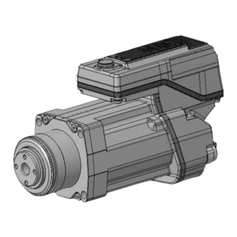
Summary of Contents for Danfoss VLT ISD 511
- Page 1 Operating Guide VLT® Servo Drive System ISD 511 drives.danfoss.com...
-
Page 3: Table Of Contents
Motor Components 3.2.3.1 Shaft 3.2.3.2 Flange 3.2.3.3 Cooling 3.2.3.4 Thermal Protection 3.2.3.5 Built-In Feedback Devices Power Supply Module (PSM 510) 3.3.1 Overview Decentral Access Module (DAM 510) 3.4.1 Overview Auxiliary Capacitors Module (ACM 510) Danfoss A/S © 2023.08 AQ377148425069en-000101/130R1213 | 3... - Page 4 Minimum Distance for M23 Angled Connector 4.7.2 Space Requirements for System Modules 4.7.3 Installation Aids and Tools Required 4.7.4 Fitting Instructions for ISD 511 Servo Drive 4.7.4.1 Overview 4.7.4.2 Mounting the ISD 511 to the Roundtable 4 | Danfoss A/S © 2023.08 AQ377148425069en-000101/130R1213...
- Page 5 Connecting the Brake Resistor on the PSM 510 Commissioning Pre-Commissioning Checklist Switching on the ISD 511 System 6.2.1 Procedure for Switching on the ISD 511 System Warnings for Commissioning ID Assignment 6.4.1 Overview Danfoss A/S © 2023.08 AQ377148425069en-000101/130R1213 | 5...
- Page 6 Installing the VLT® Servo Toolbox Software 6.6.4 VLT® Servo Toolbox Communication 6.6.4.1 Overview 6.6.4.2 Firewall 6.6.4.3 Indirect Communication 6.6.4.4 Direct Communication Motion Library 6.7.1 Function Blocks 6.7.2 Simple Programming Template for Automation Studio 6 | Danfoss A/S © 2023.08 AQ377148425069en-000101/130R1213...
- Page 7 Drive Stops Suddenly and Restart is not Possible 9.2.4 Motor Rotating in Wrong Direction 9.2.5 Motor not Generating Expected Torque 9.2.6 Drive Screaming 9.2.7 Uneven Running 9.2.8 Vibration 9.2.9 Unusual Running Noises 9.2.10 Drive Speed Drops Sharply under Load Danfoss A/S © 2023.08 AQ377148425069en-000101/130R1213 | 7...
- Page 8 DC link undervoltage (0x3220 / 0x104) 9.4.16 DC link charging error (0x3230 / 0x152) 9.4.17 DC Link unbalanced (0x3280 / 0x153) 9.4.18 UAUX high voltage (0x3291 / 0x132) 9.4.19 UAUX overvoltage (0x3292 / 0x133) 8 | Danfoss A/S © 2023.08 AQ377148425069en-000101/130R1213...
- Page 9 9.4.54 Following error (0x8611 / 0x10E) 9.4.55 Homing error on entering homing mode (0x8693 / 0x10F) 9.4.56 Homing error on start homing method (0x8694 / 0x110) 9.4.57 Homing error distance (0x8695 / 0x111) Danfoss A/S © 2023.08 AQ377148425069en-000101/130R1213 | 9...
- Page 10 ISD 511 Servo Drives 10.2.2 System Modules 10.3 Maintenance Tasks 10.4 Repair 10.5 System Module Replacement 10.5.1 Dismounting the System Modules 10.5.2 Fitting and Commissioning the System Modules 10.6 Cable Replacement 10.6.1 Overview 10 | Danfoss A/S © 2023.08 AQ377148425069en-000101/130R1213...
- Page 11 Motor Overload and Overtemperature Protection 11.5 Allowed Forces on the ISD 511 Servo Drive 11.6 Connectors on the System Modules 11.6.1 Backlink Connector 11.6.2 Brake Connectors 11.6.2.1 Brake Resistor Connector on PSM 510 11.6.3 Ethernet Connectors Danfoss A/S © 2023.08 AQ377148425069en-000101/130R1213 | 11...
- Page 12 Expansion Module Connector 11.7 Connectors on the ISD 511 Servo Drives 11.7.1 X1 and X2 Hybrid Connectors 11.8 General Specifications and Environmental Data 11.8.1 ISD 511 Servo Drives 11.8.2 System Modules 11.9 Storage 12 | Danfoss A/S © 2023.08 AQ377148425069en-000101/130R1213...
-
Page 13: Introduction
Information about the programming of the ISD 511 servo sys- motion ) Programming Guide tem. ™ 1.3 Copyright and ISD are Danfoss registered trademarks. ® ® 1.4 Approvals and Certifications Table 2: Product and System Approvals and Certifications Certification Description IEC/EN 61800-3 Adjustable speed electrical power drive systems. -
Page 14: Firmware Updates
Technical specification. Function blocks for motion control (formerly Part 1 and Part 2) Version 2.0 ® March 17, 2011. 1.5 Firmware Updates For updates to the firmware, VLT Servo Toolbox software and PLC libraries, contact Danfoss. ® 1.6 Terminology Table 3: Terminology Term... - Page 15 Programmable Logic Controller (external device for controlling the servo system). PSM 510 Power Supply Module that generates a 565–680 V DC supply. System modules Includes PSM 510, DAM 510, and the optional ACM 510 and EXM 510. Danfoss A/S © 2023.08 AQ377148425069en-000101 / 130R1213 | 15...
-
Page 16: Safety
For reasons of operator safety, use a certified electrical installer to ground the system correctly in accordance with the appli- cable local and national electrical standards and directives, and the instructions in this manual. 16 | Danfoss A/S © 2023.08 AQ377148425069en-000101 / 130R1213... - Page 17 Where a residual current-operated protective (RCD) or monitoring (RCM) device is used for protection in case of direct or indirect contact, use a type B RCD or RCM device on the supply side of the system components. Danfoss A/S © 2023.08 AQ377148425069en-000101 / 130R1213 | 17...
-
Page 18: Safety Instructions And Precautions
• Only suitably trained and qualified personnel may work on the servo system and its components or in its vicinity. • Only use accessories and spare parts approved by Danfoss. • Comply with the specified ambient conditions. •... -
Page 19: Qualified Personnel
To ensure that the product is used as intended, the following conditions must be fulfilled before use: • Everyone who uses Danfoss products in any manner must read and understand the corresponding safety regulations and the description of the intended use. -
Page 20: Forseeable Misuse
Under water. 2.7 Forseeable Misuse Any use not expressly approved by Danfoss constitutes misuse. This also applies to failure to comply with the specified operating conditions and applications. Danfoss assumes no liability of any sort for damage attributable to improper use. -
Page 21: System Description
Feed-in hybrid cable from DAM 510 to slip ring, Loop cable, 0.235 m/0.365 m (not provided by Dan- maximum 30 m (not provided by Danfoss) foss) The ISD 511 is a high-performance decentral servo motion solution. In this decentral system, the ISD 511 servo drives are operated in a DC group and controlled by a PLC. -
Page 22: Application
This reduces the required computing power of the central PLC and offers a highly flexible drive concept. Danfoss offers libraries for various IEC 61131-3 programmable PLCs. Due to the standardized and certified fieldbus interfaces of the devices, any PLC with an Ethernet POWERLINK managing node functionality according to the standards can be used. -
Page 23: Isd 511 Servo Drive Types
T01C5 1.5 Nm F087 87 mm Multi packaging [13–14] Drive voltage [30–32] Motor speed [39] Country-specific 600 V DC-link Rated speed 1000 RPM [15–16] Enclosure size [33] Mechanical brake [40] Reserved Danfoss A/S © 2023.08 AQ377148425069en-000101 / 130R1213 | 23... -
Page 24: Motor Components
The PSM 510 is available in 3 power sizes and delivers an output power of 10 kW, 20 kW, or 30 kW with 200% overload capacity for 3 seconds. To achieve an output power of up to 60 kW, 2 PSM 510 modules can be used in parallel. 24 | Danfoss A/S © 2023.08 AQ377148425069en-000101 / 130R1213... -
Page 25: Decentral Access Module (Dam 510)
DC-link capacitance buffer for the decentral servo drives The DAM 510 can be controlled via Ethernet-based fieldbus. LEDs on the front of the DAM 510 show the operating status and warnings. Danfoss A/S © 2023.08 AQ377148425069en-000101 / 130R1213 | 25... -
Page 26: Auxiliary Capacitors Module (Acm 510)
3.5.1 Overview ACM is the abbreviation for Auxiliary Capacitors Module. The ACM 510 can be connected to the ISD 511 system to store energy, enabling a controlled machine stop in emergency situations. 26 | Danfoss A/S © 2023.08 AQ377148425069en-000101 / 130R1213... -
Page 27: Expansion Module Exm
The EXM 510 supports modular machine setup by splitting the system modules into 2 control cabinets. The maximum length of the cable between the EXM 510 modules is 5 m. 5.9.5 Connecting the Expansion Module EXM 510 for further information. Danfoss A/S © 2023.08 AQ377148425069en-000101 / 130R1213 | 27... -
Page 28: Software
The firmware of the ISD 511 that is already installed on the device. • The firmware of the system modules that is already installed on the system modules (except EXM 510). 28 | Danfoss A/S © 2023.08 AQ377148425069en-000101 / 130R1213... -
Page 29: Fieldbus
Specific ports are not assigned for Ethernet POWERLINK ® 3.9 Cables 3.9.1 Feed Cables There are 3 feed cables used in the ISD 511 servo system. The feed cables are not provided by Danfoss but must conform to the specifications detailed in Table Table 6: Feed Cables... -
Page 30: Lcp Cable
3.9.3 LCP Cable The LCP cable connects the LCP to the system modules via an M8 connector. The LCP cable can be purchased from Danfoss (see the VLT® Servo Drive System ISD 510, DSD 510, MSD 510 (VLT® FlexMotion ™... - Page 31 Warn. Alarm Hand Auto Reset Illustration 7: Display Area when Connected to the PSM 510 and DAM 510 line voltage Temperature power board Actual UDC (current) Power consumption Actual UDC (voltage) Danfoss A/S © 2023.08 AQ377148425069en-000101 / 130R1213 | 31...
-
Page 32: B: Display Menu Keys
3.10.2.3 C: Navigation keys and indicator lights (LEDs) Navigation keys are used for moving the display cursor and provide operation control in local operation. There are also 3 status LEDs in this area. 32 | Danfoss A/S © 2023.08 AQ377148425069en-000101 / 130R1213... -
Page 33: D: Operation Keys And Reset
Switch on Disabled and/or the PSM 510 is in state Standby. Reset Resets the ISD 511 after a fault has been cleared. The reset is only possible when in Hand On mode. Danfoss A/S © 2023.08 AQ377148425069en-000101 / 130R1213 | 33... -
Page 34: Mechanical Installation
Register a complaint immediately with the carrier if there is visible transport damage. Register a complaint immediately with the responsible Danfoss representative if there are visible defects or the delivery is incomplete. 4.4 Safety Measures during Installation Always observe the safety instructions in this manual during installation. -
Page 35: System Modules
To avoid misalignment, ensure that the backplates are perfectly level. To ensure sufficient cooling, pay attention to the specified minimum space requirements (see 4.7.2 Space Requirements for System Modules). Ground the modules. Danfoss A/S © 2023.08 AQ377148425069en-000101 / 130R1213 | 35... -
Page 36: Drilling Templates
25 mm (273 mm – 248 mm). The minimum bending radius R for permanently static installed cable is 22.5 mm. Illustration 10: Minimum Distance for M23 Angled Connector 36 | Danfoss A/S © 2023.08 AQ377148425069en-000101 / 130R1213... -
Page 37: Space Requirements For System Modules
The modules can be mounted next to each other but require a minimum space at the top and bottom for cooling. [10.63] max. 100 [3.94] max. 120 [4.72] Illustration 11: Minimum Space Required at the Top and Bottom Danfoss A/S © 2023.08 AQ377148425069en-000101 / 130R1213 | 37... -
Page 38: Installation Aids And Tools Required
The ISD 511 servo drives are delivered with plastic M23 protection caps and a shaft protection cap. These plastic protection caps prevent damage during transport and handling. Always mount the metal protection caps if the con- nector is not used. 38 | Danfoss A/S © 2023.08 AQ377148425069en-000101 / 130R1213... -
Page 39: Mounting The Isd 511 To The Roundtable
The ISD 511 can be mounted to the roundtable from the bottom (see Illustration 13) and the top (see Illustration 14). 4 x M6 x 40 Illustration 13: Mounting the ISD 511 from the Bottom Danfoss A/S © 2023.08 AQ377148425069en-000101 / 130R1213 | 39... -
Page 40: Tightening Torques For Fixing Screws
Mount the system module with the highest output power next to the PSM 510. Mount the remaining system modules in descending order of output power. Procedure Drill the holes for mounting the backplate as per the drilling template (see 4.6.3 Drilling Templates). 40 | Danfoss A/S © 2023.08 AQ377148425069en-000101 / 130R1213... - Page 41 VLT® Servo Drive System ISD 511 Operating Guide Mechanical Installation Connect the backplates and the end cap via the click and lock method. Illustration 15: Connecting the Backplates Backplate End Cap Danfoss A/S © 2023.08 AQ377148425069en-000101 / 130R1213 | 41...
- Page 42 9.5 mm. The tightening torque is 3 Nm. Illustration 16: Mounting the Backplates in the Control Cabinet Slide the module onto the carrier at the bottom of the backplate. 42 | Danfoss A/S © 2023.08 AQ377148425069en-000101 / 130R1213...
- Page 43 To secure the module, pull down the holding clamp ([1] in Illustration 18) at the top of the backplate. Illustration 18: Pulling Down the Holding Clamp at the Top of the Backplate Holding clamp Danfoss A/S © 2023.08 AQ377148425069en-000101 / 130R1213 | 43...
- Page 44 Repeat steps 4, 5, and 6 for the remaining modules, ensuring that the lip at the left side of the 2nd module is inside the guiding groove at the right side of the 1st module ([1] in Illustration 19). Illustration 19: Guiding Groove Guiding groove 44 | Danfoss A/S © 2023.08 AQ377148425069en-000101 / 130R1213...
-
Page 45: Electrical Installation
Where a residual current-operated protective (RCD) or monitoring (RCM) device is used for protection in case of direct or indirect contact, use a type B RCD or RCM device on the supply side of the system components. Danfoss A/S © 2023.08 AQ377148425069en-000101 / 130R1213 | 45... -
Page 46: Grounding For Electrical Safety
Keep the ground wire connections as short as possible. • Connect the PE yellow/green wire of the feed-in cable to 1 of the PE screws on the front of the DAM 510, as depicted in Illustra- tion 46 | Danfoss A/S © 2023.08 AQ377148425069en-000101 / 130R1213... -
Page 47: Grounding The System Modules
If the system uses more than 5 units, ground them in groups of 5. 5.3.2 Grounding the System Modules Do not ground the system modules in daisy-chain format. Use the grounding method shown in Illustration Danfoss A/S © 2023.08 AQ377148425069en-000101 / 130R1213 | 47... -
Page 48: Grounding For Emc-Compliant Installation
16 mm (6 AWG) cable cross-section. 5.4 Grounding for EMC-Compliant Installation • Establish electrical connection between the cable shield and the enclosure using the I/O shielding plate on each module. 48 | Danfoss A/S © 2023.08 AQ377148425069en-000101 / 130R1213... - Page 49 EMC metal shielding plate • Use a cable with a shielding that has a high-coverage to reduce electrical interference. • Do not use pigtails to connect the shielding. A 360° wire connection is recommended. Danfoss A/S © 2023.08 AQ377148425069en-000101 / 130R1213 | 49...
-
Page 50: Mains Supply Requirements
Ensure that the supply has the following properties: • TN-S, TN-C, TN-CS, TT (not corner grounded) supply grounding system. • For information on the use of an IT network with transformer, contact Danfoss. • Prospective short circuit current: 5 kA. •... -
Page 51: Auxiliary Supply Requirements
The safety supply can be looped from PSM 510 to the other system modules except for ACM 510. The cable for this is not provided. For further information, see Installation. N O T I C E Ensure there is reinforced isolation between safety signals and other signals, supplies (mains supply), and exposed conduc- tive parts. Danfoss A/S © 2023.08 AQ377148425069en-000101 / 130R1213 | 51... -
Page 52: Ul Requirements
Do not forcefully connect or fit the connectors. Incorrect connection causes permanent damage to the connector. 5.9.1.3 Connecting Hybrid Cables Procedure Align the female connector of the M23 feed-in cable to the male input connector (X1) of the 1st ISD 511 servo drive. 52 | Danfoss A/S © 2023.08 AQ377148425069en-000101 / 130R1213... - Page 53 Press the connector towards the electronic housing on the servo drive until the sealing on the connector is entirely cov- ered. Tighten the M23 feed-in cable connector by rotating the threaded ring clockwise out of the flat area around the OPEN marking. Illustration 25: Connecting the M23 Feed-In Cable Danfoss A/S © 2023.08 AQ377148425069en-000101 / 130R1213 | 53...
- Page 54 Connect the female connector of the loop cable to the male connector (X1) of the next servo drive, and so on. Tighten the threaded rings by hand as described in step 5. 54 | Danfoss A/S © 2023.08 AQ377148425069en-000101 / 130R1213...
- Page 55 Male connector M23 metal blind cap Female connector Screw the M23 metal blind cap onto the unused M23 female output connector (X2) on the last servo drive in the servo system. Danfoss A/S © 2023.08 AQ377148425069en-000101 / 130R1213 | 55...
-
Page 56: Disconnecting Hybrid Cables
It is mandatory to use a 3-phase AC line choke (see 5.9.2.1.1 Connecting 1 PSM 510 to the AC Choke 5.9.2.1.2 Connecting 2 PSM 510 Modules to the AC Choke with System Splitting). 56 | Danfoss A/S © 2023.08 AQ377148425069en-000101 / 130R1213... - Page 57 PSM 510 (2 x 30 kW) 0.24 ±10% Danfoss recommends mounting the AC line choke close to the PSM 510. The maximum cable length depends on the cross-section, and the required voltage and current at the DC-link. If the AC line chokes are mounted away from the PSM 510, the maximum cable distance is 5 m.
-
Page 58: Connecting The Cables On The Power Supply Module Psm
If I/Os are required, insert the wires into the I/O connector and insert the connector (I/O PSM) [6]. If a relay is required, insert the wires into the relay connector and insert the connector (REL PSM) [7]. 58 | Danfoss A/S © 2023.08 AQ377148425069en-000101 / 130R1213... -
Page 59: Connecting The Decentral Access Module (Dam 510)
Connectors on the Top of DAM 510. Insert the 24 V IN (STO connector IN (STO DAM)) connector [3] into the DAM 510. If required, connect the external encoder connector [5]. Danfoss A/S © 2023.08 AQ377148425069en-000101 / 130R1213 | 59... -
Page 60: Connecting The Feed-In Cable
UDC+ (black, 2.5 mm AUX– (blue, 2.5 mm UDC– (gray, 2.5 mm Ethernet/fieldbus (green, RJ45 connector) STO+ (pink, 0.5 mm PE (yellow/green, 2.5 mm , fork lug) STO– (gray, 0.5 mm 60 | Danfoss A/S © 2023.08 AQ377148425069en-000101 / 130R1213... -
Page 61: Connecting The Auxiliary Capacitors Module Acm
If I/Os are required, insert the wires into the I/O connector (I/O ACM) and insert the connector [3]. If a relay is required, insert the wires into the relay connector (REL ACM) and insert the connector [4]. Danfoss A/S © 2023.08 AQ377148425069en-000101 / 130R1213 | 61... - Page 62 Operating Guide Electrical Installation Connect the ACM 510 to PE using one of the PE screws on the front side [5] and a PE wire.. The tightening torque is 3 Nm. 62 | Danfoss A/S © 2023.08 AQ377148425069en-000101 / 130R1213...
-
Page 63: Connecting The Expansion Module Exm
16 mm (6 AWG) cable cross-section. For cable cross sections see 11.6.13.1 Cable Cross-Sections for EXM 510. Procedure Insert wires [3], [4], [5], and [6] into the expansion connector. Danfoss A/S © 2023.08 AQ377148425069en-000101 / 130R1213 | 63... -
Page 64: Connecting The Brake Resistor On The Psm
(see 5.9.2.2.2 Connecting the Cables on the Bottom of the Power Supply Module PSM 510). Paralleling or series of brake resistors is not permitted. 64 | Danfoss A/S © 2023.08 AQ377148425069en-000101 / 130R1213... - Page 65 Electrical Installation STATUS PSM STATUS PSM SVS ST SVS ST NET ST NET ST LINK/ACT LINK/ACT Illustration 39: Connection of Brake Resistor on 2 PSM 510 Modules in Parallel Internal brake resistor Danfoss A/S © 2023.08 AQ377148425069en-000101 / 130R1213 | 65...
-
Page 66: Commissioning
Ethernet POWERLINK® cyclic communication is active, perform a power cycle to stop it. Disconnect the PLC and carry out a power cycle before setting IDs. Alternatively, in the POWERLINK® interface, restart the PLC in ServiceMode while parameter Basic Ethernet in Service Mode is set to Basic Ethernet enabled. 66 | Danfoss A/S © 2023.08 AQ377148425069en-000101 / 130R1213... -
Page 67: Single Device Id Assignment
Decentral Access Module (DAM 510) or Power Supply Module (PSM 510) at the same time (the LCP must be connected to the DAM 510/PSM 510 for this purpose). Danfoss A/S © 2023.08 AQ377148425069en-000101 / 130R1213 | 67... -
Page 68: Setting The Node Ids Automatically For Multiple Servo Drives And System Modules Using The Vlt® Servo
PSM 510 only: Select the Ethernet port (X1 or X2) to be used for ID assignment using parameter 54-01 Epl id assignment line. Select the start ID in parameter 54-02 Epl id assignment start id. 68 | Danfoss A/S © 2023.08 AQ377148425069en-000101 / 130R1213... -
Page 69: Dedicated Library Function Block
In the Logical View, open the menu entry [File → Import...]. In the next window, select the Danfoss_VLT_ServoMotion_V_x_y_z.zip file (according to the location on the hard drive). Click on Open. Assign the libraries to the CPU in the next window. Danfoss A/S © 2023.08 AQ377148425069en-000101 / 130R1213 | 69... -
Page 70: Constants Within The Dds_Drive Library
The names of the POUs that target the servo drive all end with _DDS. DDS_PSM • Contains POUs defined by Danfoss (name starting with DD_) and provide the functionality for the Power Supply Module (PSM 510). • The names of the POUs that target the PSM 510 all end with _PSM. -
Page 71: Instantiating Axis_Ref_Dds In Automation Studio
Open the Logical View. Initialize each instance with its node number and the slot name it is connected to (for example, IF3). Initialize each instance of a drive with its DriveType. Danfoss A/S © 2023.08 AQ377148425069en-000101 / 130R1213 | 71... -
Page 72: Instantiating Psm_Ref In Automation Studio
To create a link to the physical ACM 510, link each instance of ACM_REF to 1 physical ACM 510. This makes it the logical representation of 1 physical ACM 510. Open the Logical View. Initialize each instance with its node number and the slot name it is connected to (for example, IF3). 72 | Danfoss A/S © 2023.08 AQ377148425069en-000101 / 130R1213... -
Page 73: Importing A Servo Drive Into Automation Studio
Now add the PSM 510, DAM 510, or ACM 510 to the Ethernet POWERLINK interface of the controller in the Physical View: ® Select the menu entry[Open → System Designer] to show the System Designer. Danfoss A/S © 2023.08 AQ377148425069en-000101 / 130R1213 | 73... -
Page 74: I/O Configuration And I/O Mapping
These settings configure the cyclic communication with the device. These parameters are required for the library to work. N O T I C E It is possible to use copy and paste to apply the same I/O configuration to multiple devices of the same type. 74 | Danfoss A/S © 2023.08 AQ377148425069en-000101 / 130R1213... - Page 75 Set Module supervised to off for the servo drives and the PSM 510/DAM 510/ACM 510. The parameter is found in the I/O configuration of the device. Illustration 43: I/O Configuration of an ISD 511 Device Illustration 44: I/O Mapping after Successful Configuration Danfoss A/S © 2023.08 AQ377148425069en-000101 / 130R1213 | 75...
-
Page 76: Setting The Plc Cycle Time
Version V4.x: Open the B&R Help Explorer and go to [Automation Software → Getting Started → Creating programs in Automation Studio → Ex- ample project for a target system with CompactFlash]. 76 | Danfoss A/S © 2023.08 AQ377148425069en-000101 / 130R1213... -
Page 77: Programming Guidelines For Automation Studio
6.6 VLT® Servo Toolbox Software 6.6.1 Overview The VLT Servo Toolbox is a standalone PC software designed by Danfoss. It is used for parameterization and diagnostics of the ® system modules. It is also possible to operate the devices in a non-productive environment. -
Page 78: System Requirements
Check that your system meets the system requirements specified in 6.6.2 System Requirements. Download the VLT Servo Toolbox installation file from the Danfoss website. ® Right-click on the .exe file and select Run as administrator. Follow the on-screen instructions to complete the installation process. - Page 79 Turn off the checksum validation of the specific protocol in the Wireshark preferences. ® Disable IPv6 on the network interfaces used for communication on the PC: Procedure Open the Network and Sharing Center. Select Change adapter settings. Danfoss A/S © 2023.08 AQ377148425069en-000101 / 130R1213 | 79...
-
Page 80: Direct Communication
On the left, click on Change adapter settings. Right-click on the network interface used for fieldbus communication and select Properties. Uncheck all checkboxes except the one for Internet Protocol Version 4 (TCP/IPv4). 80 | Danfoss A/S © 2023.08 AQ377148425069en-000101 / 130R1213... - Page 81 Select Use the following IP address and use 192.168.100.240 as the IP address and 255.255.255.0 as the subnet mask. Leave all other fields empty. Illustration 50: Internet Protocol Version 4 (TCP/IPv4) Properties Danfoss A/S © 2023.08 AQ377148425069en-000101 / 130R1213 | 81...
-
Page 82: Motion Library
Technical Specification Function blocks for motion control (Formerly Part 1 and Part 2) Version 2.0 March 17, 2011. ® In addition to the PLCopen functionality, Danfoss offers further functions for the servo system. ® The following PLCopen characteristics apply to all function blocks: ®... -
Page 83: Operation
This functionality stores the position actual value at a rising or falling edge of the configured digital input. 7.2 Operating Status Indicators The operating status of the ISD 511 servo drives, PSM 510, DAM 510, and ACM 510 is indicated via the LEDs on each device. Danfoss A/S © 2023.08 AQ377148425069en-000101 / 130R1213 | 83... -
Page 84: Operating Leds On The Isd511 Servo Drive
(Link/activity status of Hybrid In (X1)) Flashing Ethernet link established and active. No link. Green Ethernet link established. LINK/ACT X2 (Link/activity status of Hybrid Out (X2)) Flashing Ethernet link established and active. No link. 84 | Danfoss A/S © 2023.08 AQ377148425069en-000101 / 130R1213... -
Page 85: Operating Leds On The Psm
Ethernet link established and active. No link. Green Ethernet link established. LINK/ACT X2 (Link/activity status of Out) Flashing Ethernet link established and active. No link. POWERLINK : Refer to the corresponding fieldbus standard. ® Danfoss A/S © 2023.08 AQ377148425069en-000101 / 130R1213 | 85... -
Page 86: Operating Leds On The Dam
Green Ethernet link established. LINK/ACT X2 (Link/activity status of Hybrid Out) Flashing Ethernet link established and active. No link. Green Ethernet link established. LINK/ACT X3 Flashing Ethernet link established and active. 86 | Danfoss A/S © 2023.08 AQ377148425069en-000101 / 130R1213... -
Page 87: Operating Leds On The Acm
Network status of the device (see corresponding fieldbus stand- ard). Green Ethernet link established. LINK/ACT X1 (Link/activity of In) Flashing Ethernet link established and active. No link. Green Ethernet link established. LINK/ACT X2 Flashing Ethernet link established and active. Danfoss A/S © 2023.08 AQ377148425069en-000101 / 130R1213 | 87... - Page 88 VLT® Servo Drive System ISD 511 Operating Guide Operation Color Flash status Description (Link/activity status of Out) No link. POWERLINK : Refer to the corresponding fieldbus standard. ® 88 | Danfoss A/S © 2023.08 AQ377148425069en-000101 / 130R1213...
-
Page 89: Safety Concept
If required, implement a manual reset function according to EN ISO 13849-1. For automatic restart without manual reset, observe the requirements detailed in paragraph 6.3.3.2.5 of EN ISO 12100:2010 or equivalent standard. Danfoss A/S © 2023.08 AQ377148425069en-000101 / 130R1213 | 89... -
Page 90: Qualified Personnel For Working With Functional Safety
Hardware fault tolerance HFT = n means that n + 1 faults may lead to a loss of the safety function. MTTF EN ISO 13849-1 Mean time to failure – dangerous 90 | Danfoss A/S © 2023.08 AQ377148425069en-000101 / 130R1213... -
Page 91: Installation
8.6 Installation Only Danfoss cables can be used for the installation of the servo system, however cables from other suppliers can be used for the user connection to the STO terminal STO DAM (Pins 3 and 4) on the Decentral Access Module (DAM 510). -
Page 92: Protective Measures
Bit-wise readout of the status. 8.8.1 Commissioning Test using Libraries Depending on the application, 1 or both of the following libraries are required to program the commissioning test: • Danfoss Library MC_ReadAxisInfo_DDS MC_ReadStatus_DDS MC_ReadAxisError_DDS MC_Reset_DDS 92 | Danfoss A/S © 2023.08 AQ377148425069en-000101 / 130R1213... -
Page 93: Operation Of The Sto Function
Operating Guide Safety Concept Table 23: Commissioning Test using Libraries Test steps Reason for the test step Expected result for Danfoss library Run the application (all the ser- Check that the application Application runs as expected. vo drives are enabled). -
Page 94: Error Codes
Error code 0xFF81/0x11F means that there is a fault on the servo drive that can only be reset by carrying out a power cycle. Com- plete the commissioning test after the power cycle. Operation of the servo system can only be resumed if the test is completed successfully. If error code 0xFF81/0x11F or 0xFF85/0x120 is issued again, contact Danfoss Service. 8.9.2 Fault Reset To reset faults, change bit 7 of the controlword from 0 to 1. -
Page 95: Maintenance, Security, And User Accessibility
Safety Concept N O T I C E The PSM 510, DAM 510, and ACM 510 do not contribute to the dangerous failure rate of the Danfoss system and can there- fore be excluded from safety-related calculations. Compliance to the claimed SIL and PL is only possible if the diagnostic test is executed once per year. -
Page 96: Diagnostics
N O T I C E If the fault cannot be eliminated by 1 of the measures listed in the troubleshooting tables, notify Danfoss Service. Have the following information available to enable Danfoss to provide help quickly and effectively: •... -
Page 97: Motor Rotating In Wrong Direction
Defective bearing. • Defects on connected mechanics. • Incorrect control loop parameters. Troubleshooting • Check the shaft. • Check for loose mechanical components on the connected mechanics. • Check the parameter settings. Danfoss A/S © 2023.08 AQ377148425069en-000101 / 130R1213 | 97... -
Page 98: Drive Speed Drops Sharply Under Load
Press [Status] + [▵]/[▿] to adjust the contrast. Display is defective. Replace the faulty LCP or connection cable. 9.3.2 Open Power Fuses or Circuit Breaker Trip This fault applies to the PSM 510 and DAM 510. 98 | Danfoss A/S © 2023.08 AQ377148425069en-000101 / 130R1213... -
Page 99: Dc-Link Voltage Too Low (Error 0X3220/0X104)
Possible causes • The servo drives are consuming more power on the U line than allowed. Troubleshooting • Ensure that the number of servo drives on 1 line does not exceed 68. Danfoss A/S © 2023.08 AQ377148425069en-000101 / 130R1213 | 99... -
Page 100: Aux Overvoltage (Error 0X3292/0X133)
Possible causes • Faulty brake resistor. • Internal/external brake resistor not connected. Troubleshooting • Remove the power to the device, wait for the discharge time to elapse, then replace the brake resistor. 100 | Danfoss A/S © 2023.08 AQ377148425069en-000101 / 130R1213... -
Page 101: Brake Chopper Error
0x2313 0x161 High cont. power Warning, error High continuous power high pwr ovld overload overload error. 9.4.4 Continuous power overload (0x2314 / 0x162) This error is valid for PSM 510. Danfoss A/S © 2023.08 AQ377148425069en-000101 / 130R1213 | 101... -
Page 102: Overcurrent Short Circuit (0X2320 / 0X163)
Current on the AUX line has reached AUX curr limit current the user-defined limit for fault. 9.4.9 AUX user limit current warning (0x2394 / 0x128) This error is valid for PSM 510 and DAM 510. 102 | Danfoss A/S © 2023.08 AQ377148425069en-000101 / 130R1213... -
Page 103: Aux Supply Failure (0X2395 / 0X129)
This occurs when a phase on mains is missing, or when the mains is imbalanced. 9.4.14 DC link overvoltage (0x3210 / 0x103) This error is valid for PSM 510, DAM 510, ACM 510, and ISD 511. Danfoss A/S © 2023.08 AQ377148425069en-000101 / 130R1213 | 103... -
Page 104: Dc Link Undervoltage (0X3220 / 0X104)
Severity (warning/error/trip Description LCP name ® lock) 0x3291 0x132 high voltage Warning above warning limit. UAUX high volt 9.4.19 UAUX overvoltage (0x3292 / 0x133) This error is valid for DAM 510. 104 | Danfoss A/S © 2023.08 AQ377148425069en-000101 / 130R1213... - Page 105 DC link low Warning The DC-link voltage is lower than the UDC low volt voltage low-voltage warning limit. 9.4.24 UAUX charging error (0x3297 / 0x154) This error is valid for DAM 510. Danfoss A/S © 2023.08 AQ377148425069en-000101 / 130R1213 | 105...
- Page 106 Too many auto fault resets have been autoreset fail set failure executed in intended time interval. 9.4.29 Device overtemperature (0x4210 / 0x157) This error is valid for PSM 510, DAM 510, ACM 510, and ISD 511. 106 | Danfoss A/S © 2023.08 AQ377148425069en-000101 / 130R1213...
- Page 107 Inrush fault. perature: DC link Too many transitions into state Operation enabled in a short time period. 9.4.34 Inrush overtemperature AUX line (0x4294 / 0x13D) This error is valid for DAM 510. Danfoss A/S © 2023.08 AQ377148425069en-000101 / 130R1213 | 107...
- Page 108 Output U failure phase U not successful (an excessive offset is phase U present). Contact Danfoss. 9.4.39 Output phase V failure (0x5412 / 0x124) This error is valid for ISD 511. 108 | Danfoss A/S © 2023.08 AQ377148425069en-000101 / 130R1213...
- Page 109 Check the configuration file sent to the device and re- place it. If the error persists, contact Danfoss. 9.4.44 Configuration parameters limits error (0x6383 / 0x164) This error is valid for PSM 510, DAM 510, and ACM 510.
- Page 110 This error appears when the maxi- overload mum power limit of the brake chopper module is reached. 9.4.49 External brake chopper overload (0x7182 / 0x143) This error is valid for PSM 510. 110 | Danfoss A/S © 2023.08 AQ377148425069en-000101 / 130R1213...
- Page 111 Trip lock int sensor err Absolute position sensor error. sor error If the error persists, contact Danfoss. 9.4.52 External position sensor error (0x7380 / 0x10D) This error is valid for DAM 510. Table 78: External position sensor error (0x7380 / 0x10D)
- Page 112 Error The fieldus communication has been comm inter- terrupted interrupted while the device was ena- rupt bled. 9.4.59 Fan feedback inconsistent (0xFF21 / 0x145) This error is valid for PSM 510. 112 | Danfoss A/S © 2023.08 AQ377148425069en-000101 / 130R1213...
- Page 113 Severity (warning/error/trip lock) Description LCP name ® 0xFF63 0x118 Timing violation 4 Trip lock Contact Danfoss. timing err 4 9.4.65 Timing violation 5 (0xFF64 / 0x119) This error is valid for ISD 511. Danfoss A/S © 2023.08 AQ377148425069en-000101 / 130R1213 | 113...
- Page 114 FW pack err scription mismatch match the package description. 9.4.71 Firmware: Power cycle needed (0xFF71 / 0x11C) This error is valid for PSM 510, DAM 510, ACM 510, and ISD 511. 114 | Danfoss A/S © 2023.08 AQ377148425069en-000101 / 130R1213...
- Page 115 0xFF81 0x11F STO mis- Trip lock Dual diagnosis of STO voltage not STO mismatch match plausible. 9.4.76 P_STO error (0xFF85 / 0x120) This error is valid for ISD 511. Danfoss A/S © 2023.08 AQ377148425069en-000101 / 130R1213 | 115...
- Page 116 [– abs((G –G )/2) to out of range range abs ((G –G )/2)] 9.4.81 UDU Min Blending distance out of range (0xFF94 / 0x293) This error is valid for ISD 511. 116 | Danfoss A/S © 2023.08 AQ377148425069en-000101 / 130R1213...
- Page 117 Table 108: Sign of life error (0xFF95 / 0x14E) Code PROFINET code Name Severity (warning/error/trip lock) Description LCP name ® 0xFF95 0x14E Sign of life error Error Sign of life error. SOL error Danfoss A/S © 2023.08 AQ377148425069en-000101 / 130R1213 | 117...
- Page 118 The ISD 511 servo drives are largely maintenance free. Only the shaft seal on the ISD 511 (if used) is subject to wear. The mainte- nance tasks must be performed by qualified personnel. No other tasks are required. 118 | Danfoss A/S © 2023.08 AQ377148425069en-000101 / 130R1213...
- Page 119 A shorter interval may be necessary depending on the application. Contact Danfoss for more information. 10.4 Repair Do not attempt to repair the products. Defective products must be returned to Danfoss. Contact the local Danfoss sales company for information about returns.
- Page 120 Unscrew the screw [2] on the I/O shielding plate [3]. Pull the I/O shielding plate upwards to remove it. Release the securing clamp [1] at the top of the module. Illustration 59: Releasing the Securing Clamp 120 | Danfoss A/S © 2023.08 AQ377148425069en-000101 / 130R1213...
- Page 121 Do not forcefully connect or fit the connectors. Incorrect connection causes permanent damage to the connectors. 10.6.2 Feed-In Cable Replacement 10.6.2.1 Disconnecting the Feed-In Cable Procedure Disconnect the Power Supply Module (PSM 510) from its power source (mains network and all auxiliary supplies). Danfoss A/S © 2023.08 AQ377148425069en-000101 / 130R1213 | 121...
- Page 122 Ensure that there is no mechanical tension on the cables. Tighten the threaded rings of the connectors on both servo drives. Reconnect any cables that were connected to the I/O ports on both servo drives. 122 | Danfoss A/S © 2023.08 AQ377148425069en-000101 / 130R1213...
- Page 123 Use a screwdriver to remove the fuses and replace them with the same number of identical type fuses. Illustration 62: Removing the Fuse Replace the cover and tighten the screws. The tightening torque is 2 Nm. Danfoss A/S © 2023.08 AQ377148425069en-000101 / 130R1213 | 123...
- Page 124 10.9 Product Returns Danfoss products can be returned for disposal at no charge. A prerequisite for this is that they are free of deposits, such as oil, grease, or other types of contamination that hampers disposal. Furthermore, foreign materials or third-party components cannot be included with the returned product.
- Page 125 Check the nameplates and compare them with the order data. Use the part number for reference. The part number uniquely identi- fies the drive type. Ensure that the nameplates are clearly legible. The servo drives can be identified externally only by the original Danfoss nameplates. VLT ® ISD511 ISD511XXXXXXXXXXXXXXXXXXXXXXXXXXXXXXXXXX Part.
- Page 126 Illustration 67: Nameplate on the Front of PSM 510 Part number Data matrix Serial number Notes Customer part number MAC addresses Output Warning The following data is shown on the nameplate on the front of DAM 510. 126 | Danfoss A/S © 2023.08 AQ377148425069en-000101 / 130R1213...
- Page 127 Accept. for field wiring - Min. 75dC, Cu Internal Overload Protection 105% E171278 Industrial Control Equipment Danfoss A/S 6430 Nordborg, Denmark Danfoss Ltd. Oxford Road, UB9 4LH Denham, UK Illustration 69: Example Nameplate on the Side of the System Modules Type code Maximum power...
- Page 128 – tection. Maximum output frequency – Shaft diameter mm [inch] 38.8 h8 [15.275 h8] – Pole pairs – – Flange size mm [inch] 87 [3.425] – Functional safety – – – 128 | Danfoss A/S © 2023.08 AQ377148425069en-000101 / 130R1213...
- Page 129 Peak power P Rated power P Minimum resistance Ω General Protective measures – Overload, short-circuit, and ground fault protection Line filter in accordance with EN 61800-3 – Category C3 Cooling – Integrated fan Danfoss A/S © 2023.08 AQ377148425069en-000101 / 130R1213 | 129...
- Page 130 11.2.4 Characteristic Data for Auxiliary Capacitors Module (ACM 510) Table 113: Characteristic Data for ACM 510 Definition Unit Value DC-link V DC 565–680 ±10% DC-link capacitance µF 2750 V DC 24/48 ±10% 130 | Danfoss A/S © 2023.08 AQ377148425069en-000101 / 130R1213...
- Page 131 (2.6) (2.7) (1.5) 55.2 M6 13 Ø5.7 (0.3) (0.2) (0.2) (0.6 ) Ø12.1 (2.7) (0.5) (1.5) (0.9) (3.4) 50.5 195.4 (1.1) 92.35 (7.7) (3.6) Illustration 70: ISD 511 Servo Drive Dimensions Danfoss A/S © 2023.08 AQ377148425069en-000101 / 130R1213 | 131...
- Page 132 [0.2] STATUS PSM SVS ST NET ST LINK/ACT 2xØ5.2 [0.2] [10.63] Illustration 72: Dimensions of PSM 510 11.3.4 Dimensions of Decentral Access Module (DAM 510) All dimensions are in mm [in]. 132 | Danfoss A/S © 2023.08 AQ377148425069en-000101 / 130R1213...
- Page 133 [0.2] STATUS DAM SVS ST NET ST LINK/ACT Ø5.2 [0.2] [10.63] Illustration 73: Dimensions of DAM 510 11.3.5 Dimensions of Auxiliary Capacitors Module (ACM 510) All dimensions are in mm [in]. Danfoss A/S © 2023.08 AQ377148425069en-000101 / 130R1213 | 133...
- Page 134 11.3.6 Dimensions of Expansion Module (EXM 510) All dimensions are in mm (in). 87.3 [3.43] [0.98] [0.98] 144.75 Ø5.2 [5.70] 21.3 [0.2] [0.62] [1.97] [0.84] Ø5.2 [0.2] Illustration 75: Dimensions of EXM 510 134 | Danfoss A/S © 2023.08 AQ377148425069en-000101 / 130R1213...
- Page 135 Infinite life with standard 99% reliability. • Safety factor = 2 11.6 Connectors on the System Modules 11.6.1 Backlink Connector The backlink connector is at the top of the backside of all the system modules. Danfoss A/S © 2023.08 AQ377148425069en-000101 / 130R1213 | 135...
- Page 136 VLT® Servo Drive System ISD 511 Operating Guide Specifications Illustration 77: Pin Assignment of Backlink Connector Table 116: Pin Assignment of Backlink Connector Description 24/48 V FE: Functional earth DC– 136 | Danfoss A/S © 2023.08 AQ377148425069en-000101 / 130R1213...
- Page 137 Description Pins Ratings X1 IN Ethernet IN According to standard 100BASE-T. 1: TX+ 2: TX– X2 OUT Ethernet OUT1 3: RX+ 4: – 5: – 6: RX– 7: – 8: – Danfoss A/S © 2023.08 AQ377148425069en-000101 / 130R1213 | 137...
- Page 138 N O T I C E Only PELV potential can be connected to the digital inputs and outputs. 11.6.5 UAUX Connector The U connector is on the Power Supply Module (PSM 510). 138 | Danfoss A/S © 2023.08 AQ377148425069en-000101 / 130R1213...
- Page 139 There is an LCP connector on the front of all the system modules. It is used to connect the LCP directly via a cable. Illustration 82: LCP Connector (M8, 6 pole) Danfoss A/S © 2023.08 AQ377148425069en-000101 / 130R1213 | 139...
- Page 140 AWG 4 (minimum 60 °C, Cu) (minimum 60 °C, Cu) (minimum 75 °C, Cu) 11.6.8 Relay Connector The relay connector is used for a user-defined reaction and is located as follows: 140 | Danfoss A/S © 2023.08 AQ377148425069en-000101 / 130R1213...
- Page 141 11.6.9 STO Connectors 11.6.9.1 STO Connectors on PSM 510 There is 1 input and 1 output STO connector on the Power Supply Module (PSM 510). Illustration 85: STO Output Connector on PSM 510 Danfoss A/S © 2023.08 AQ377148425069en-000101 / 130R1213 | 141...
- Page 142 11.6.9.2 STO Connectors on the DAM 510 11.6.9.2.1 STO Connectors on the Top of DAM 510 There is 1 input and 1 output STO connector on the top of the Decentral Access Module (DAM 510). 142 | Danfoss A/S © 2023.08 AQ377148425069en-000101 / 130R1213...
- Page 143 11.6.9.2.2 STO Connector on the Bottom of DAM 510 There is 1 output STO connector on the bottom of the Decentral Access Module (DAM 510). The output is for the hybrid cable. Danfoss A/S © 2023.08 AQ377148425069en-000101 / 130R1213 | 143...
- Page 144 Conductor cross-section range: 0.2–6 mm (AWG 24–AWG 10) Plug terminal tightening torque: 0.5–0.8 Nm (4.43–7.08 in-lb) 11.6.11 AUX Connector The AUX connector is on the bottom of the Decentral Access Module (DAM 510). 144 | Danfoss A/S © 2023.08 AQ377148425069en-000101 / 130R1213...
- Page 145 Nominal current: Depends on the number of servo drives in the applica- DAM 510. tion. Maximum current: 150 mA (see Table 132) Fulfill the following specifications: • BISS/SSI Danfoss A/S © 2023.08 AQ377148425069en-000101 / 130R1213 | 145...
- Page 146 , solid or flexible (AWG 18–AWG 4) Only use with ferrule without plastic sleeve with CRIMPFOX 16 S. Use shielded conductors for UDC (DC+, DC–). Plug terminal tightening torque: 1.7–1.8 Nm (15.05–15.93 in-lb) 146 | Danfoss A/S © 2023.08 AQ377148425069en-000101 / 130R1213...
- Page 147 The hybrid cable provides the supply (mains and auxiliary), the communication lines, and the safety supply for each line of servo drives. Input and output connectors are connected inside the servo drive. Illustration 94: Pin Assignment of X1 Male Hybrid Connector (M23) Danfoss A/S © 2023.08 AQ377148425069en-000101 / 130R1213 | 147...
- Page 148 IP65 according to EN 60529 IP69K (flange and sealing) according to ISO 20653 Indoor only Vibration test Class 3M7 according to IEC 60721-3-3 Maximum relative humidity Storage/transport: 5–95% (non-condensing) Stationary use: 5–95% (non-condensing) 148 | Danfoss A/S © 2023.08 AQ377148425069en-000101 / 130R1213...
- Page 149 Derating of output current (1% / 100 m) from 1000 m to 3000 m. Operation above 3000 m is not permitted. EMC standard for emission and immunity EN 61800-3 (second environment) Danfoss A/S © 2023.08 AQ377148425069en-000101 / 130R1213 | 149...
- Page 150 To recondition the electrolytic capacitors, servo drives and system components that are not in service must be connected to a sup- ply source once per year to allow the capacitors to charge and discharge. Otherwise the capacitors could suffer permanent damage. 150 | Danfoss A/S © 2023.08 AQ377148425069en-000101 / 130R1213...
- Page 151 Disconnection..................56 AUX......................144 Expansion module................146 X1/X2 Hybrid connector..............147 Copyright......................13 Cyclic synchronous position mode............83 Configuration Automation Studio™..........74 Cyclic synchronous velocity mode............83 Mapping....................74 Connector....................138 Indirect communication................79 Inertia measurement mode..............83 DAM_REF Danfoss A/S © 2023.08 AQ377148425069en-000101/130R1213 | 151...
- Page 152 Profile torque mode..................83 Overview....................77 Profile velocity mode.................. 83 Subtools....................77 Programming guidelines PC requirements..................78 Automation Studio™................77 Installation..................... 78 Protection rating Communication...................78 System modules................149 PSM_REF Automation Studio™................72 X1/X2 connector..................147 PSM 510 Overview..................24 152 | Danfoss A/S © 2023.08 AQ377148425069en-000101/130R1213...
- Page 153 ® ® Ethernet. It is an open protocol managed by the Ethernet POWERLINK ® Standardization Group (EPSG). It was introduced by Austrian automation company B&R in 2001. Danfoss A/S © 2023.08 AQ377148425069en-000101/130R1213 | 153...
- Page 154 Program organization unit. This can be a program, function block, or func- tion. Power Supply Module. Pulse width modulation. RCCB Residual current circuit breaker. 154 | Danfoss A/S © 2023.08 AQ377148425069en-000101/130R1213...
- Page 155 Auxiliary supply, provides power to the control electronics of the ISD 511 servo drives and the Power Supply Module (PSM 510), Decentral Access Module (DAM 510), and Auxiliary Capacitors Module (ACM 510). Servo Toolbox A Danfoss pc software tool used for parameter setting and diagnostics of ® Servo Drive systems ®...
- Page 156 Danfoss can accept no responsibility for possible errors in catalogs, brochures, and other printed material. Danfoss reserves the right to alter its products without notice. This also applies to products already on order provided that such alterations can be made without subsequential changes being necessary in specifications already agreed. All trademarks in this material are property of the respective companies.
Need help?
Do you have a question about the VLT ISD 511 and is the answer not in the manual?
Questions and answers