Sign In
Upload
Manuals
Brands
Danfoss Manuals
Servo Drives
VLT ISD 511
Danfoss VLT ISD 511 Manuals
Manuals and User Guides for Danfoss VLT ISD 511. We have
1
Danfoss VLT ISD 511 manual available for free PDF download: Operating Manual
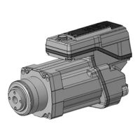
Danfoss VLT ISD 511 Operating Manual (156 pages)
Brand:
Danfoss
| Category:
Servo Drives
| Size: 15 MB
Table of Contents
Table of Contents
3
Introduction
13
Purpose of the Operating Guide
13
Additional Resources
13
Copyright
13
Approvals and Certifications
13
Firmware Updates
14
Terminology
14
Safety
16
Safety Symbols
16
Important Safety Warnings
16
Safety Instructions and Precautions
18
Operational Safety
18
Qualified Personnel
19
Due Diligence
19
Intended Use
19
Prohibited Application Areas
19
Forseeable Misuse
20
Service and Support
20
System Description
21
Overview of the ISD 511 System
21
Application
22
VLT® Integrated Servo Drive ISD
22
Overview of the ISD 511 Servo Drive
22
ISD 511 Servo Drive Types
23
Motor Components
24
Shaft
24
Flange
24
Cooling
24
Thermal Protection
24
Built-In Feedback Devices
24
Power Supply Module (PSM 510)
24
Overview
24
Decentral Access Module (DAM 510)
25
Overview
25
Auxiliary Capacitors Module (ACM 510)
26
Overview
26
Expansion Module EXM
27
Software
28
Fieldbus
29
Ethernet POWERLINK
29
Cables
29
Feed Cables
29
Loop Cable
29
LCP Cable
30
Local Control Panel (LCP)
30
Overview of the Local Control Panel
30
Layout of the Local Control Panel
30
A: Display Area
30
B: Display Menu Keys
32
C: Navigation Keys and Indicator Lights (Leds)
32
D: Operation Keys and Reset
33
Mechanical Installation
34
Items Supplied
34
Transport
34
Inspection on Receipt
34
Safety Measures During Installation
34
Installation Environment
34
Overview
34
ISD 511 Servo Drive
34
System Modules
35
Preparation for Installation
35
ISD 511 Servo Drive
35
Drilling Templates
36
Installation Procedure
36
Space Requirements for ISD
36
Minimum Distance for M23 Angled Connector
36
Space Requirements for System Modules
37
Installation Aids and Tools Required
38
Fitting Instructions for ISD 511 Servo Drive
38
Overview
38
Mounting the ISD 511 to the Roundtable
39
Tightening Torques for Fixing Screws
40
Fitting Instructions for System Modules
40
Electrical Installation
45
Warnings for Electrical Installation
45
Electrical Environmental Conditions
45
Grounding for Electrical Safety
46
Grounding the ISD 511 Servo Drive
46
Grounding the System Modules
47
Grounding for EMC-Compliant Installation
48
Mains Supply Requirements
50
Fuses
50
Circuit Breakers
50
Auxiliary Supply Requirements
51
Fuses
51
Safety Supply Requirements
51
UL Requirements
52
Connecting the Components
52
Connecting the ISD 511 Servo Drive
52
Electrical Installation Warnings for ISD 511 Servo Drive
52
General Instructions for Cable Installation
52
Disconnecting Hybrid Cables
56
Connecting the Power Supply Module PSM
56
AC Line Choke
56
Connecting the Cables on the Power Supply Module PSM
58
Connecting the Decentral Access Module (DAM 510)
59
Connecting the Cables on the Top of the Decentral Access Module DAM
59
Connecting the Feed-In Cable
60
Connecting the Auxiliary Capacitors Module ACM
61
Connecting the Expansion Module EXM
63
Connecting the Brake Resistor on the PSM
64
Commissioning
66
Pre-Commissioning Checklist
66
Switching on the ISD 511 System
66
Procedure for Switching on the ISD 511 System
66
Warnings for Commissioning
66
ID Assignment
66
Overview
66
Single Device ID Assignment
67
Setting the Node ID for a Single Servo Drive Manually Using the VLT® Servo Toolbox
67
Setting the Node ID for a Single Servo Drive Manually Using the LCP
67
Multiple Device ID Assignment
67
Setting the Node Ids Automatically for Multiple Servo Drives and System Modules Using the VLT® Servo
68
Toolbox
68
Setting the Node Ids Automatically for Multiple Servo Drives Using the LCP
68
Setting the Node Ids Automatically for Multiple Servo Drives and System Modules Using the LCP
68
Dedicated Library Function Block
69
Programming with Automation Studio
69
Requirements for Programming with Automation Studio
69
Creating an Automation Studio™ Project
69
Including the Servo Motion Libraries into an Automation Studio™ Project
69
Constants Within the Dds_Drive Library
70
Instantiating AXIS_REF_DDS in Automation Studio
71
Instantiating PSM_REF in Automation Studio
72
Instantiating DAM_REF in Automation Studio
72
Instantiating ACM_REF in Automation Studio
72
Importing a Servo Drive into Automation Studio
73
Importing PSM 510, DAM 510 and ACM 510 into Automation Studio
73
I/O Configuration and I/O Mapping
74
Setting the PLC Cycle Time
76
Connecting to the PLC
76
Programming Guidelines for Automation Studio
77
VLT® Servo Toolbox Software
77
Overview
77
System Requirements
78
Installing the VLT® Servo Toolbox Software
78
VLT® Servo Toolbox Communication
78
Overview
78
Firewall
78
Indirect Communication
78
Direct Communication
80
Motion Library
82
Function Blocks
82
Simple Programming Template for Automation Studio
82
Operation
83
Operating Modes
83
Motion Functions
83
Operating Status Indicators
83
Operating Leds on the ISD511 Servo Drive
84
Operating Leds on the PSM
85
Operating Leds on the DAM
86
Operating Leds on the ACM
87
Safety Concept
89
Functional Description
89
Safety Precautions
89
Qualified Personnel for Working with Functional Safety
90
Applied Standards and Compliance
90
Abbreviations and Conventions
90
Installation
91
Protective Measures
92
Application Example
92
Commissioning Test
92
Commissioning Test Using Libraries
92
Operation of the STO Function
93
Error Codes
94
Fault Reset
94
Functional Safety Characteristic Data
94
Maintenance, Security, and User Accessibility
95
Diagnostics
96
Faults
96
Troubleshooting for the ISD 511 Servo Drive
96
Drive Not Running/Starting Slowly
96
Drive Hums and Draws High Current
96
Drive Stops Suddenly and Restart Is Not Possible
96
Motor Rotating in Wrong Direction
97
Motor Not Generating Expected Torque
97
Drive Screaming
97
Uneven Running
97
Vibration
97
Unusual Running Noises
97
Drive Speed Drops Sharply under Load
98
Leds Not Lighting up
98
Drive Protection Trips Immediately
98
Troubleshooting for the Servo System
98
LCP Display Is Dark/Not Functioning
98
Open Power Fuses or Circuit Breaker Trip
98
DC-Link Voltage too Low (Error 0X3220/0X104)
99
Current Overload Trip (Error 0X2396/0X15C)
99
High Cont. Power Overload (Error 0X2313/0X161)
99
Continuous Power Overload (Error 0X2314/0X162)
99
AUX Overcurrent (Error 0X2391/0X125)
99
AUX Overvoltage (Error 0X3292/0X133)
100
AUX Undervoltage (Error 0X3294/0X135)
100
Mains Phase Loss (Error 0X3130/0X12F)
100
Generic Application Error (Error 0X1000/ 0X100)
100
Grounding Fault
100
Brake Resistor Error
100
Brake Chopper Error
101
Internal Fan Error
101
Error Codes for ISD 511 Servo System
101
No Error (0X0000 / 0X0)
101
Generic Application Error (0X1000 / 0X100)
101
High Cont. Power Overload (0X2313 / 0X161)
101
Continuous Power Overload (0X2314 / 0X162)
101
Overcurrent Short Circuit (0X2320 / 0X163)
102
Ground Fault (0X2330 / 0X151)
102
AUX Overcurrent (0X2391 / 0X125)
102
AUX User Limit Current (0X2393 / 0X127)
102
AUX User Limit Current Warning (0X2394 / 0X128)
102
AUX Supply Failure (0X2395 / 0X129)
103
Current Overload Trip (0X2396 / 0X15C)
103
Power Overload Trip (0X2397 / 0X12B)
103
Mains Phase Loss (0X3130 / 0X12F)
103
DC Link Overvoltage (0X3210 / 0X103)
103
DC Link Undervoltage (0X3220 / 0X104)
104
DC Link Charging Error (0X3230 / 0X152)
104
DC Link Unbalanced (0X3280 / 0X153)
104
UAUX High Voltage (0X3291 / 0X132)
104
UAUX Overvoltage (0X3292 / 0X133)
104
Advertisement
Advertisement
Related Products
Danfoss VLT Integrated Servo Drive ISD 510 System
Danfoss VLT ISD 410
Danfoss iC7-60EA3N05-245A
Danfoss iC7-60EA3N05-302A
Danfoss iC7-60EA3N05-385A
Danfoss iC7-60EA3N05-588A
Danfoss iC7-60EA3A05-385A
Danfoss iC7-60EA3A05-730A
Danfoss iC7-60EA3A05-880A
Danfoss iC7-60EA3A05-1000
Danfoss Categories
Controller
DC Drives
Thermostat
Control Unit
Air Compressor
More Danfoss Manuals
Login
Sign In
OR
Sign in with Facebook
Sign in with Google
Upload manual
Upload from disk
Upload from URL