
Related Manuals for WAGO 750 Series


Summary of Contents for WAGO 750 Series
- Page 1 WAGO I/O System 750/753 Decentralized Automation Technology Serie 750, 753 System manual | Version 3.3.1...
- Page 2 We wish to point out that the software and hardware terms as well as the trademarks of companies used and/or mentioned in the present manual are generally protected by trademark or patent. WAGO is a registered trademark of WAGO Verwaltungsgesellschaft mbH. System manual | Version: 3.3.1...
-
Page 3: Table Of Contents
Serie 750, 753 Table of Contents Table of Contents Provisions ........................ 6 Validity of this Documentation ................. 6 Intended Use ...................... 6 Typographical Conventions .................. 7 Legal Information ..................... 9 Safety .......................... 10 General Safety Regulations................... 10 Elektrische Sicherheit .................... 10 Mechanical Safety .................... - Page 4 Table of Contents Serie 750, 753 Mounting Position and Clearances............... 31 5.2.6 DIN-Rail Characteristics ................ 32 5.2.7 EMC Installations.................. 33 5.2.8 Data Security .................... 33 5.2.9 Designing the System Supply................ 34 Field Supply Layout .................... 35 Special Applications and Environments ............... 35 Marine and Offshore..................
- Page 5 Serie 750, 753 Table of Contents 10.2 Protected Rights .................... 61 10.3 Accessories ...................... 62 System manual | Version: 3.3.1...
-
Page 6: Provisions
1.1 Validity of this Documentation This document applies to the I/O system: WAGO I/O System 750/753 (Series 750, 753). The complete operating instructions for the I/O system consists of several, applicable documents. The I/O system must only be installed and operated in accordance with the complete operating instructions. -
Page 7: Typographical Conventions
Provisions Warranty and Liability The provisions of the latest WAGO General Terms and Conditions of Deliveries and Ser- vices (GTC) apply as well as the Software License Terms for Standard Software (SW-Li- cense) applicable to software products und software embedded in WAGO hardware prod- ucts, both available at: ü www.wago.com. - Page 8 Provisions Serie 750, 753 Sequence of Action ü This symbol identifies a precondition. 1. Action step 2. Action step ð This symbol identifies an intermediate result. ð This symbol identifies the result of an action. • Individual action step Lists •...
-
Page 9: Legal Information
1.4 Legal Information Intellectual property The intellectual property of this document belongs to WAGO GmbH & Co. KG. The repro- duction and distribution of its content (in whole or in part) is prohibited, unless otherwise provided by statutory provisions, written agreements or this document. In case of doubt, the written consent of WAGO GmbH &... -
Page 10: Safety
Safety Serie 750, 753 Safety This section lists installation regulations that must be observed for safe operation of the I/O System. 2.1 General Safety Regulations • This documentation is part of the Products. Retain the documentation for the entire service life of the Products. Pass on the documentation to any subsequent user of the Products. -
Page 11: Mechanical Safety
• Do not place products on the data or power jumper contacts. • If product fails, communication to downstream products may be interrupted. • Products from the WAGO I/O System 750/753 can be operated in combination with those of the WAGO I/O System 750 XTR. For combined operation, take the specifica- tions for the ambient conditions for both I/O Systems into account. -
Page 12: System Features
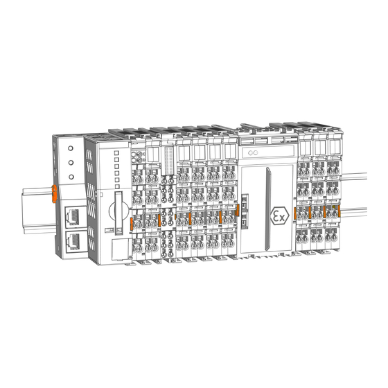
System Features Serie 750, 753 System Features 3.1 Component Structure 3.1.1 Designs Head Stations Figure 1: Example Head Station Housings The housings of head stations (fieldbus couplers or controllers) may differ, for instance in terms of: • The connection level with or without field-side power supply (Eco) •... -
Page 13: Structure Of The Head Stations
Serie 750, 753 System Features 3.1.2 Structure of the Head Stations Beispielansicht PFC Figure 3: Beispielansicht PFC & Product Manual Reset button 8 System Contacts [} 21] Data contacts & Product Manual Display elements: Power supply status & Product Manual Display elements: System status ®... - Page 14 System Features Serie 750, 753 Beispielansicht Feldbuskoppler/Controller Figure 4: Beispielansicht Controller Slot for Mini-WSB (optional) 8 Marking Elements [} 23] 8 Versions [} 18] 8 System Contacts [} 21] Data contacts & Product Manual Display elements: Power supply status Display elements: Fieldbus status & Product Manual ® Access to open the associated CAGE CLAMP con- 8 Conductor Termination [} 53]...
-
Page 15: I/O Module Configuration
Serie 750, 753 System Features 3.1.3 I/O Module Configuration ® Example View of the 750 Series I/O Module (CAGE CLAMP Connections) ® Figure 5: 750 Series I/O Module with CAGE CLAMP Connections (Example) 8 Marking Elements [} 23] Slot for Mini-WSB (optional) 8 Versions [} 18] Data contacts 8 System Contacts [} 21]... - Page 16 System Features Serie 750, 753 ® Example View of the 750 Series I/O Module (Push-in CAGE CLAMP Connections) ® Figure 6: 750 Series I/O Module with Push-in CAGE CLAMP Connections (Example) 8 Marking Elements [} 23] Slot for Mini-WSB (optional) 8 Versions [} 18] Data contacts 8 System Contacts [} 21]...
- Page 17 Serie 750, 753 System Features Example View of the 753 Series I/O Module (Pluggable Connector) Figure 7: 753 Series I/O Module (Example) 8 Marking Elements [} 23] Slot for Mini-WSB (optional) 8 Versions [} 18] Data contacts 8 System Contacts [} 21] Indicators & Product Manual ® 8 Conductor Termination [} 53] Access to open the associated CAGE CLAMP con-...
-
Page 18: Product Identification
WAGO I/O System 750 XTR Blue + dark gray WAGO I/O System 750 XTR – intrinsically safe modules (Ex i) Color Coding for Identifying Functionality To allow you to get an overview of the component classes present in a node quickly and easily, they are color-coded. -
Page 19: Marking
& Product Manual. CE mark With the CE mark, WAGO declares that the product meets the applicable requirements as set out in Community harmonization legislation per EC Regu- lation 765/2008, which allows the product to carry this mark. -
Page 20: Table 4 Explanation Of The Example Of Different Marking
“RCM” mark With the RCM mark (Regulatory Compliance Mark), WAGO declares that the product meets the applicable requirements according to Australian standards. “CCC” mark With the CCC (China Compulsory Certification) -
Page 21: Identification
Serie 750, 753 System Features Content Description “EAC” icon The EAC mark indicates that the product conforms to the safety requirements set forth in the EEU technical requirements. “EAC Ex” icon The EAC Ex mark indicates that the product meets the safety requirements set forth in the EEU tech- nical requirements for operation in hazardous ar- eas. -
Page 22: Power Jumper Contacts
System Features Serie 750, 753 1. Forwarding of the system supply to subsequent I/O modules 2. Communication between head station and I/O modules Figure 8: Data Contacts 3.1.5.2 Power Jumper Contacts Figure 9: Example of Power Jumper Contact Arrangement (Left: Blade Contacts; Right: Spring Contacts) System manual | Version: 3.3.1... -
Page 23: Din-Rail Contact
Serie 750, 753 System Features Potentials of the Power Jumper Contacts Figure 10: Potentials of the Power Jumper Contacts 1st potential of the field power supply 2nd potential of the field power supply, usually 0 V/ground potential Functional ground (FE) 3.1.5.3 DIN-Rail Contact Many components of the I/O system transmit electromagnetic interference to the DIN-rail via DIN-rail contacts. -
Page 24: Electrical Structure
– If there is a power supply infeed, above the individual connections • On I/O modules of the 750 and 753 Series: – Above the indicators • On some I/O modules of the 750 Series: – Above the individual connections 3.2 Electrical Structure 3.2.1 Potential Levels... -
Page 25: System Supply
• SELV/PELV power supplies shall be used. • Power must be supplied simultaneously to all system power supply units. WAGO recommends using the same voltage source to realize the power supply. • Use a suitable overcurrent protection for each infeed. Product-specific information is &... -
Page 26: Field Supply
System Features Serie 750, 753 3.2.3 Field Supply Figure 14: Field Supply Infeed (Example) Observe the following requirements for the field supply: • For non-hazardous active voltages per EN/UL/IEC 61010-1, use SELV/PELV power supplies. • Use suitable overcurrent protection for each infeed. You can find detailed product infor- &... - Page 27 Serie 750, 753 System Features • Suitable Isolation Devices, e.g., non-automatic circuit-breaker • Supply Modules – Bus power supplies – Supply module Depending on the application area, the following may also be needed: • Filter modules • Distance modules • Voltage buffer –...
-
Page 28: Functions
Functions Serie 750, 753 Functions 4.1 Process Image After switching on, the head station identifies the inserted I/O modules that send or ex- pect to receive data (data width > 0). The head station creates an internal local process image from the data width, the module type and the position of the I/O module in the node. -
Page 29: Planning
• Grouping by potential group • Optical delimitation of the potential groups For fast, effortless planning, use the WAGO Configurator Smart Designer. Number of I/O Modules The maximum number of I/O modules that can be operated in one node depends on sev- eral factors: •... -
Page 30: Structure Guidelines
Planning Serie 750, 753 • Addressability: Up to 250 I/O modules can be addressed, depending on the head station. I/O modules that do not have any process or diagnostic data (e.g., distance modules) do not need to be taken into account when calculating the number. •... -
Page 31: Protective Conductor And Protective Ground
Serie 750, 753 Planning 5.2.4 Protective Conductor and Protective Ground The I/O System does not provide any protective conductor functionality via the field con- nections. If a field device connected to the I/O System requires a protective ground con- nection, this connection must not be implemented via the I/O System’s field connection. If hazardous active voltages are used, the DIN-rail must be suitably connected to protective ground (PE). -
Page 32: Din-Rail Characteristics
Planning Serie 750, 753 Figure 16: Coordinate model: width (x), height (y), depth (z) Overview of Mounting Positions The mounting positions shown correspond to the final orientation of the products within the additional enclosure. Horizontal, left Horizontal, up Horizontal, down (nominal mounting position) (floor mounting position (ceiling mounting position Horizontal, right... -
Page 33: Emc Installations
A low-impedance connection between shielding and ground achieves better shielding performance. For this purpose, connect the shielding over a large surface area, e.g., using the WAGO Series 790 Shield Connection System. This is especially recom- mended for large-scale systems where equalizing or high impulse currents may occur. -
Page 34: Designing The System Supply
WAGO recommends putting control components and control networks behind a fire- wall. • In the control components, close all ports and services (e.g., for WAGO-I/O-CHECK and CODESYS) not required by your application to minimize the risk of cyber attacks and to enhance cybersecurity. -
Page 35: Field Supply Layout
Consumption of System Supply (5 V)” in the technical data of the corresponding Product Manual. For fast, effortless supply design, use the WAGO Configurator Smart Designer. A calculation example is available at: 8 Examples and Aids [} 42] 5.4 Field Supply Layout Designing the field supply requires knowledge of the entire field-side current consumption of the installed I/O modules. -
Page 36: Table 7 High-Isolation Filter Modules
Planning Serie 750, 753 No additional filter module is required for field supply with a nominal value different from 24 VDC. No filter module is required for field supply different from 24 VDC. Marine Applications per DNV • Class A: all areas except bridge and open deck •... - Page 37 Serie 750, 753 Planning Filter module for field-side power supply, 24 VDC, HI GF (750-624/020-002) or Filter module for field-side power supply, 24 VDC, HI (750-624/020-000) Distance module, 24 VDC / 230 VAC (750-616/030-000) Power supply, 230 VAC/DC, with diagnostics, with fuse holder (750-611) or Power supply, 230 VAC/DC, without diagnostics, with fuse holder (750-609) or Power supply, 230 VAC/DC, without diagnostics, without fuse holder (750-612) System supply (24 VDC)
-
Page 38: Ex I Applications
Planning Serie 750, 753 5.5.2 Ex i Applications Some I/O modules are intended to be connected with devices located in hazardous ar- eas. To ensure safety and reliability in these applications, several additional requirements must be considered: • The node structure meets the additional requirements specified below for the power supply as well as the requirements for air and creepage distances. -
Page 39: Marine And Offshore Ex I Applications
Serie 750, 753 Planning Clearance and Creepage Distance Requirements For all sections of a node that contain I/O modules for Ex i use, stricter requirements re- garding clearances and creepage distances apply. Before the first such node section, the respective Ex i supply module (750-606 or 750-625/000-001) ensures the required dis- tance. - Page 40 Planning Serie 750, 753 Figure 20: Power Supply Concept for Marine Applications in Ex i Zone – Class A Filter module, 24 VDC, HI GF (750-626/020-002) or filter module, 24 VDC, HI (750-626/020-000) Bus supply module, 24 VDC (750-602) or bus supply module, 24 VDC, with fuse (750-601) or bus supply module, 24 VDC, with fuse and diagnostics (750-610) Filter module, 24 VDC, HI GF (750-624/020-002) or filter module, 24 VDC, HI (750-624/020-000)
-
Page 41: Functional Safety
Serie 750, 753 Planning Figure 21: Power Supply Concept for Marine Applications in Ex i Zone – Class B Filter module, 24 VDC, HI GF (750-626/020-002) or filter module, 24 VDC, HI (750-626/020-000) Filter module, 24 VDC, HI GF (750-626/020-002) or filter module, 24 VDC, HI (750-626/020-000) Bus supply module, 24 VDC, Ex i, with diagnostics (750-606) or bus supply module, 24 VDC, Ex i (750-625/000-001) Ex i I/O modules... -
Page 42: Examples And Aids
Field supply 2 (24 VDC) 5.6 Examples and Aids 5.6.1 Aids WAGO can help you with a wide range of useful products and software solutions. The aids for project planning include: • e!COCKPIT e!COCKPIT is an integrated development environment that supports every automation task, from hardware configuration and programming, to simulation and visualization, to commissioning –... -
Page 43: I/O Test
• Head station: 3 W • I/O module: 1 W 5.6.2 I/O Test The WAGO I/O System allows easy, effective testing of your wiring with an I/O test. For example, WAGO software solutions such as e!COCKPIT and WAGO-I/O-CHECK make it possible to: •... - Page 44 Planning Serie 750, 753 Detailed instructions are available in the & product manuals for e!COCKPIT and WAGO- I/O-CHECK. System manual | Version: 3.3.1...
-
Page 45: Transport And Storage
Serie 750, 753 Transport and Storage Transport and Storage The original packaging offers optimal protection during transport and storage. • Store the products in suitable packaging; preferably, in the original packaging. • Only transport the products in suitable containers/packaging. • Make sure the product contacts are not contaminated or damaged when packing or un- packing. -
Page 46: Assembly And Disassembly
Assembly and Disassembly Serie 750, 753 Assembly and Disassembly Note Assembly must be preceded by professional planning! Before you assemble an I/O System node, make sure that the intended assembly follows all safety precautions and planning instructions in this documentation. The following information must be provided: •... -
Page 47: Attaching An I/O Module
Serie 750, 753 Assembly and Disassembly Figure 23: Locking the Head Station ð The head station is now locked on the DIN-rail. 7.4 Attaching an I/O Module 1. Position the I/O module in such a way that the grove and spring are connected to the preceding and, if applicable, the following components. -
Page 48: Removing A Head Station From The Din-Rail
Assembly and Disassembly Serie 750, 753 Figure 25: Snapping the I/O Module On 3. Check that the I/O module is seated securely on the DIN-rail and in the assembly. ð Once the I/O module has snapped into place, the electrical connections are establish for the data contacts and power contacts (if any) to the head station or to the preced- ing and, if applicable, following I/O module. -
Page 49: Removing An I/O Module
• When removing the products, pay attention to the power jumper contacts! Removing 750 Series I/O Modules 1. Pull the orange release tab on the I/O module upwards. To remove I/O modules with two release tabs from an assembly, both tabs must be pulled at the same time! - Page 50 Assembly and Disassembly Serie 750, 753 Figure 28: Pulling the Release Tab 2. Pull the I/O module out of the assembly by the release tab. ð When the I/O module is pulled out of the assembly, the electrical connections of the data and power contacts are disconnected.
-
Page 51: Inserting Coding Keys
Serie 750, 753 Assembly and Disassembly Figure 30: Detaching the 753 Series I/O Module 3. Pull the I/O module out of the assembly by the release tab. ð When the I/O module is pulled out of the assembly, the electrical connections of the data and power contacts are separated. - Page 52 Assembly and Disassembly Serie 750, 753 Figure 32: Inserting Coding Keys ð Due to its design, each coding pin allows four different coding options (i.e.; 16 dif- ferent options using two coding keys). 3. Put the pluggable connector on the I/O module. Figure 33: Plugging the Connector into Place ð...
-
Page 53: Conductor Termination
Serie 750, 753 Conductor Termination Conductor Termination 8.1 Conductor Termination ® ® CAGE CLAMP - and Push-in CAGE CLAMP Connectors are designed for solid, stranded and fine-stranded conductors. Only one conductor may be connected to each clamping unit. 8.1.1 Connecting Conductors to CAGE CLAMP® ®... -
Page 54: Connecting Conductors To Push-In Cage Clamp
Conductor Termination Serie 750, 753 8.1.2 Connecting Conductors to Push-in CAGE CLAMP® Stranded and fine-stranded conductors with ferrules, as well as solid conductors can be plugged directly into ® Push-in CAGE CLAMP Connectors. For all other conductor types, an operating tool must be used to open the Push-in CAGE ®... -
Page 55: Decommissioning
Serie 750, 753 Decommissioning Decommissioning 9.1 Shutting Down 1. Bring the process to a secure stop. 2. Disconnect the respective system component from the power supply. 3. Check if the voltage is isolated. 4. Protect the system component from accidental or unauthorized restart. 5. -
Page 56: Appendix
10.1.1 Special Notes Regarding Explosion Protection The following warning notices are to be posted in the immediate proximity of the product (WAGO I/O System 750/753): • WARNING – DO NOT REMOVE OR REPLACE FUSED WHILE ENERGIZED! • WARNING – DO NOT DISCONNECT WHILE ENERGIZED! •... -
Page 57: Ul Requirements From Installation Regulations
Installation instructions revised on 2014-07-04 For cULus examination, the WAGO I/O System Series 750, 753 and 758 s have only been investigated for risk of fire and electrical shock (in accordance with UL508 and CSA C22.2 No. -
Page 58: Ul Ordinary Locations Per Report Reference E175199-20181019
These devices are to be used with Optical Transceivers / SFP modules as prescribed in the Installation instructions of WAGO. Such SFP modules need to be in compliance with Laser Class I in accordance with 21 CFR 1040 and rated max. 1 W Neutral shall not be connected. -
Page 59: Ul Ordinary Locations Per Report Reference E175199-20230421
Serie 750, 753 Appendix Manual statements issued on 2021-07-16 For Bus coupler, Bus controller for 24V system supply input voltage an external fuse, rated max. 2A, slow acting, min. 30Vdc shall be used. For field supplied Module (also supplied by Power jumper contacts) for 24V field supply input voltage an external fuse, rated max. - Page 60 Appendix Serie 750, 753 WARNING - USE MODULE 750-642 ONLY WITH AN- AVERTISSEMENT : UTILISEZ LE MODULE RÉF. TENNA MODULE 758 -910 750-642 UNIQUEMENT AVEC LE MODULE D'AN- TENNE RÉF. 758-910 ! Module 750-538 only Manual shall contain CONTROL DRAWING No.750538 with its entity parameters. “In Hazardous Locations, Non-Incendive only when installed per Control Drawing No.
-
Page 61: Ul Hazardous Locations Per Report Reference E198726-2023-01-31
Serie 750, 753 Appendix 10.1.2.7 UL Hazardous Locations per Report Reference E198726-2023-01-31 Because the following information refers to language-specific regulations, standards or certifications applicable to the specific installation and operation location, it is presented in the respective original language. Installation and operating instructions Issued on 2023-01-31 This equipment is suitable for use in Class I, Division 2, Groups A, B, C and D Or nonhaz- ardous locations only. -
Page 62: Table 9 Recommended Accessories
Table 9: Recommended Accessories Item number Item Description Item Description Communication Cable 750-920 Communication Cable 4-pole male header – D-Sub 9 socket; 2.5 m WAGO DIN-Rails 210-1xx DIN-rails Steel bluish, galvanized, chromated; copper Buffer Modules 787 Series Capacitive Buffer Mod- See product catalog ules... - Page 63 Serie 750, 753 List of Tables List of Tables Table 1 Color coding of Component Types ..................Table 2 Color Coding of Component Classes................. Table 3 Explanation of the Marking Example ................. Table 4 Explanation of the Example of Different Marking............... Table 5 Production Number ......................
- Page 64 ® Figure 5 750 Series I/O Module with CAGE CLAMP Connections (Example) ......® Figure 6 750 Series I/O Module with Push-in CAGE CLAMP Connections (Example) ..... Figure 7 753 Series I/O Module (Example)................. Figure 8 Data Contacts ....................... Figure 9 Example of Power Jumper Contact Arrangement (Left: Blade Contacts;...
- Page 65 Serie 750, 753 List of Figures ® Figure 36 Connecting Conductor to Push-in CAGE CLAMP ............System manual | Version: 3.3.1...
- Page 66 WAGO is a registered trademark of WAGO Verwaltungsgesellschaft mbH. Copyright – WAGO GmbH & Co. KG – All rights reserved. The content and structure of the WAGO websites, catalogs, videos and other WAGO media are subject to copyright. Distri- bution or modification of the contents of these pages and videos is prohibited. Furthermore, the content may neither be copied nor made available to third parties for commercial pur-...
Need help?
Do you have a question about the 750 Series and is the answer not in the manual?
Questions and answers