Table of Contents
Advertisement
Quick Links
Advertisement
Table of Contents

Subscribe to Our Youtube Channel
Related Manuals for Epson N6 Series


Summary of Contents for Epson N6 Series
- Page 1 6-Axis Robots N6 series MANIPULATOR MANUAL Rev.2 EM187R3735F...
- Page 3 6-Axis Robots N6 series Manipulator Manual Rev. 2 Copyright 2018 SEIKO EPSON CORPORATION. All rights reserved. N6 Rev.2...
- Page 4 FOREWORD Thank you for purchasing our robot products. This manual contains the information necessary for the correct use of the manipulator. Please carefully read this manual and other related manuals before installing the robot system. Keep this manual handy for easy access at all times. WARRANTY The robot and its optional parts are shipped to our customers only after being subjected to the strictest quality controls, tests, and inspections to certify its compliance with our high...
- Page 5 TRADEMARKS Microsoft, Windows, and Windows logo are either registered trademarks or trademarks of Microsoft Corporation in the United States and/or other countries. Other brand and product names are trademarks or registered trademarks of the respective holders. NOTICE No part of this manual may be copied or reproduced without authorization. The contents of this manual are subject to change without notice.
- Page 6 Regarding battery disposal The crossed out wheeled bin label that can be found on your product indicates that this product and incorporated batteries should not be disposed of via the normal household waste stream. To prevent possible harm to the environment or human health please separate this product and its batteries from other waste streams to ensure that it can be recycled in an environmentally sound manner.
- Page 7 Structure of Control System N6 Manipulators can be used with the following combinations of controllers and software. Controller : RC700-A Software : EPSON RC+ 7.0 Ver.7.3.4 or later Setting by Software This manual contains setup procedures using the software. EPSON Those sections are indicated by the symbol on the left.
- Page 8 N6 Rev.2...
-
Page 9: Table Of Contents
Table of Contents Setup & Operation 1. Safety 1.1 Conventions....................3 1.2 Design and Installation Safety ..............4 1.3 Operation Safety ..................5 1.4 Emergency Stop ..................7 1.5 How to Move Arms with the Electromagnetic Brake ......9 Arm Motion ...................10 1.6 Precaution for Operation in Low Power Status ........11 1.7 Warning Labels ..................12 Location of Labels ................14 2. - Page 10 Table of Contents 4.4 Precautions for Auto Acceleration/Deceleration ........64 5. Motion Range 5.1 Motion Range Setting by Pulse Range (for Each Joint) ...... 65 5.1.1 Max. Pulse Range: N6-A1000** ..........66 5.1.2 Max. Pulse Range: N6-A850**R ..........69 5.2 Restriction of Manipulator Operation ........... 72 5.3 Coordinate System ................
- Page 11 Table of Contents 3.1 Base Cover ..................114 3.2 Joint #1 Cover ..................116 3.2.1 N6-A1000** (Joint #1 Cover) ..........116 3.2.2 N6-A850**R (Joint #1 Cover) ..........118 3.3 Joint #1 Inside Cover ................. 120 3.3.1 N6-A1000** (Joint #1 Inside Cover) ........120 3.3.2 N6-A850**R (Joint #1 Inside Cover) ........
- Page 12 Table of Contents 5.1.2 Joint #1 (N6-A1000*B): Cable direction: Upward and Downward ............271 5.1.3 Joint #1 (N6-A850*R): Cable direction: Standard (backward) ........274 5.1.4 Joint #1 (N6-A850*BR): Cable direction: Upward ............277 5.2 Replacing the Joint #2 Actuator Unit ..........280 5.2.1 Joint #2 (N6-A1000**) ............
-
Page 13: Setup & Operation
Setup & Operation This volume contains information for setup and operation of the Manipulators. Please read this volume thoroughly before setting up and operating the Manipulators. -
Page 15: Safety
Setup & Operation 1. Safety 1. Safety Installation and transportation of the Manipulators and robotic equipment shall be performed by qualified personnel and should conform to all national and local codes. Please read this manual and other related manuals before installing the robot system or before connecting cables. -
Page 16: Design And Installation Safety
The following items are safety precautions for design personnel: ■ Personnel who design and/or construct the robot system with this product must read the Safety chapter in the EPSON RC+ User’s Guide. Designing and/or constructing the robot system without understanding the safety requirements is... -
Page 17: Operation Safety
Setup & Operation 1. Safety 1.3 Operation Safety The following items are safety precautions for qualified Operator personnel: ■ Please carefully read the Safety-related Requirements in the Safety chapter of the Safety and Installation manual. Operating the robot system without understanding the safety requirements is extremely hazardous and may result in serious bodily injury and/or severe equipment damage to the robot system. - Page 18 Setup & Operation 1. Safety ■ Whenever possible, only one person should operate the robot system. If it is necessary to operate the robot system with more than one person, ensure that all people involved communicate with each other as to what they are doing and take all necessary safety precautions.
-
Page 19: Emergency Stop
Setup & Operation 1. Safety 1.4 Emergency Stop If the Manipulator moves abnormally during operation, immediately press the Emergency Stop switch. Pressing the Emergency Stop switch immediately changes the Manipulator to deceleration motion and stops it at the maximum deceleration speed. However, avoid pressing the Emergency Stop switch unnecessarily while the Manipulator is running normally. - Page 20 Setup & Operation 1. Safety For details of the Safeguard system, refer to the following manuals. EPSON RC+ User’s Guide 2. Safety - Installation and Design Precautions - Safeguard System Safety and Installation 2.6 Connection to EMERGENCY Connector To check brake problems, refer to the following manuals.
-
Page 21: How To Move Arms With The Electromagnetic Brake
Emergency Stop switch. Otherwise, you cannot immediately stop the arm falling due to an erroneous operation. The arm falling may cause equipment damage to and/or malfunction of the Manipulator. EPSON After releasing the Emergency Stop switch, execute the following command in [Command Window]. -
Page 22: Arm Motion
Setup & Operation 1. Safety Arm Motion N6-A1000** Arm #2 Arm #3 Arm #1 Arm #5 Arm #4 Arm #6 Base N6 Rev.2... -
Page 23: Precaution For Operation In Low Power Status
Setup & Operation 1. Safety N6-A850**R Base Arm #3 Arm #1 Arm #4 Arm #2 Arm #5 Arm #6 1.6 Precaution for Operation in Low Power Status In the low power status, the Manipulator operates at low speed and low torque. Carefully operate the Manipulator since it may get your hands or fingers caught during operation. -
Page 24: Warning Labels
Setup & Operation 1. Safety 1.7 Warning Labels The Manipulator has the following warning labels. The warning labels are attached around the locations where specific dangers exist. Be sure to comply with descriptions and warnings on the labels to operate and maintain the Manipulator safely. - Page 25 Setup & Operation 1. Safety Location Warning Label NOTE Do not enter the work space when the Manipulator is operating. It is extremely hazardous since the Arm may collide and cause serious safety problems. Only authorized personnel should perform sling work and operate a crane and a forklift.
-
Page 26: Location Of Labels
Setup & Operation 1. Safety Location of Labels N6-A1000** N6-A1000*B N6 Rev.2... - Page 27 Setup & Operation 1. Safety N6-A850**R N6-A850*BR N6 Rev.2...
-
Page 28: Specifications
“Ceiling mounting”, you need to change the model settings. N6-A850**R is for “Ceiling mounting” only. “Table Top mounting” is not available. For details on how to change the model settings, refer to 5.5 Changing the Robot, and EPSON RC+ User’s Guide Robot Configuration. N6 Rev.2... -
Page 29: Part Names
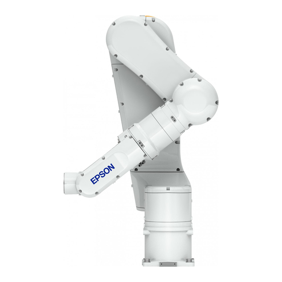
Setup & Operation 2. Specifications 2.2 Part Names N6-A1000** Arm #2 LED Lamp Arm #3 Joint #2 Joint #3 Joint #6 Arm #6 Arm #4 Joint #4 Arm #5 Arm #1 Joint #5 Joint #1 Base User cable connector User Air 2 Air 1 One-touch fittings for ø6 mm pneumatic tubes Ether 1... - Page 30 Setup & Operation 2. Specifications N6-A850**R Base Joint #1 Arm #3 Joint #3 Arm #1 Joint #4 Joint #2 Arm #4 LED Lamp Joint #5 Arm #5 Arm #2 Joint #6 Arm #6 User cable connector User Air 1 Air 2 One-touch fittings for ø6 mm pneumatic tubes Ether 2...
- Page 31 Setup & Operation 2. Specifications N6-A1000** / N6-A850**R Cable direction: Standard (backward) Cable direction: Upward and Downward One-touch fittings for ø6 mm pneumatic tubes One-touch fittings for ø6 mm pneumatic tubes Air 1 Air 2 Air 2 Air 1 Ethernet User cable Power cable cable...
-
Page 32: Outer Dimensions
Setup & Operation 2. Specifications 2.3 Outer Dimensions [Unit: mm] 2.3.1 Basic Orientation N6-A1000*: Cable direction: Standard (backward) N6 Rev.2... - Page 33 Setup & Operation 2. Specifications N6-A1000*B: Cable direction: Upward and Downward N6-A850*R: Cable direction: Standard (backward) N6 Rev.2...
- Page 34 Setup & Operation 2. Specifications N6-A850*BR: Cable direction: Upward N6 Rev.2...
-
Page 35: Orientation With The Maximum Arm Length
Setup & Operation 2. Specifications 2.3.2 Orientation with the Maximum Arm Length N6-A1000** N6-A850**R N6 Rev.2... -
Page 36: Standard Motion Range
Setup & Operation 2. Specifications 2.4 Standard Motion Range ■ Pay attention to the arm pose of the basic arms (Arms #1, #2, and #3) when operating the Manipulator. Arm #5 moves keeping a constant angle regardless of the arm pose. Depending on the arm pose of the basic arms, the wrist may collide with the Manipulator. - Page 37 Setup & Operation 2. Specifications N6-A850**R Top View Joint #2 0 pulse position Joints #4, 6 0 pulse position Joint #1 0 pulse position Joints #3, 5 0 pulse position Lateral View Lateral View Robot Robot installation face installation face * P point : Intersection of the rotation centers for Joint #4, #5, and #6 A: No entry range (Refer to Setup &...
-
Page 38: Specifications
Setup & Operation 2. Specifications 2.5 Specifications 2.5.1 Specifications table Item Specification Model Number N6-A1000** N6-A850**R Model Name Ceiling mounting, Mounting type Ceiling mounting Table Top mounting Weight (excluding cables) 69 kg (152 lb.) 64 kg (141 lb.) Driving method All joints AC servo motor Joint #1... - Page 39 Mounting types other than “Table Top mounting” and “Ceiling mounting” are out of the specification. If you prefer other mounting types, please contact us. For details on how to change the model settings, refer to 5.5 Changing the Robot, and EPSON RC+ User’s Guide Robot Configuration.
- Page 40 Setup & Operation 2. Specifications *8: The exhaust system in the Cleanroom model Manipulator draws air from the base interior and arm cover interior. A crack or other opening in the base unit can cause loss of negative air pressure in the outer part of the arm, which can cause increased dust emission.
-
Page 41: How To Set The Model
Setup & Operation 2. Specifications 2.5.2 Option N6 series have the following options. For details, refer to Setup & Operation 6. Options. Brake release unit The option for moving the arms manually by turning off the Electromagnetic brakes. For EU... -
Page 42: Environment And Installation
Setup & Operation 3. Environment and Installation 3. Environment and Installation Installation and transportation of robots and robotic equipment shall be performed by qualified personnel and should conform to all national and local codes. 3.1 Environmental Conditions A suitable environment is essential for the robot system to function properly and safely. Be sure to install the robot system in an environment that meets the following conditions: Item Conditions... -
Page 43: Unpacking, Transportation, And Relocation
Setup & Operation 3. Environment and Installation 3.2 Unpacking, Transportation, and Relocation Using a cart or similar equipment, transport the Manipulator in the same conditions as it was delivered. Observe the following when unpacking the Manipulator. The installation shall be made by qualified installation personnel and should conform to all national and local codes. - Page 44 (1) Turn ON the Controller. (2) Change the Manipulator orientation so that it is easy to support when removing it. Recommended posture: Basic orientation. Command EPSON > Pulse 0, 0, 0, 0, 0, 0 N6-A1000** N6-A850**R (3) Turn OFF the power for all devices and disconnect the power cable connector and signal cable connector from the controller.
- Page 45 (2) Change the Manipulator orientation so that it is easy to support when removing it. Recommended posture: N6-A1000**: Joint #2 -65deg, Joint #3 -25deg N6-A850**R: Basic orientation EPSON Command N6-A1000**: > Go AglToPls (0, -65, -25, 0, 0, 0) N6-A850**R: > Go AglToPls (0, 0, 0, 0, 0, 0)
- Page 46 Setup & Operation 3. Environment and Installation Using Eyebolt Before carrying the Manipulator, make sure to check that the eyebolts are securely fastened. After transporting the Manipulator, remove the eyebolts and keep them for future use. The eyebolts (accessory, 3 pcs) and wire must be strong enough to withstand the weight (See the figures below).
-
Page 47: Mounting Dimensions
Setup & Operation 3. Environment and Installation 3.3 Mounting Dimensions 3.3.1 Mounting Area Be sure to have the following space available in addition to the space for mounting the Manipulator, Controller, and peripheral equipment. Space for teaching points Space for maintenance and inspections (for installing jigs) Space for cables NOTE To prevent the power cable from bending, make sure to leave space for 150mm When... - Page 48 Setup & Operation 3. Environment and Installation N6-A1000**: Cable direction: Upward and Downward Cleanroom model Standard model *: Example of space for Manipulator base for “Cable direction: Upward and Downward”: Design the base table as shown above considering not interfering with the positioning holes and the installation holes.
-
Page 49: Motion Range
Setup & Operation 3. Environment and Installation N6-A850**R: Cable direction: Standard (backward) Cable direction: Upward Standard model Cleanroom model *: Example of space for Manipulator base for “Cable direction: Upward”: Design the base table as shown above considering not interfering with the positioning holes and the installation holes. - Page 50 Setup & Operation 3. Environment and Installation N6-A1000**: Maximum motion range N6 Rev.2...
- Page 51 Setup & Operation 3. Environment and Installation N6-A1000**: Radius of arm rotation (Basic orientation) Motion range (CP motion) P point* 310 R510 (Motion position) * When the P point is 310mm apart from the center, upward and downward distance in CP motion will be the maximum. N6 Rev.2...
- Page 52 Setup & Operation 3. Environment and Installation N6-A850**R: Maximum motion range N6 Rev.2...
-
Page 53: Installation
■ To ensure safety, a safeguard must be installed for the robot system. For details on the safeguard, refer to the Installation and Design Precautions in the Safety chapter of the EPSON RC+ User’s Guide. ■ Anchor the Manipulator before turning ON the power to or operating the Manipulator. - Page 54 Setup & Operation 3. Environment and Installation Ceiling mounting To mount the Manipulator on the ceiling, install the eyebolts on the tap hole for transportation and lift up the Manipulator by the wire. Check that the eyebolts are securely fastened before carrying the Manipulator. After transporting the Manipulator, remove the eyebolts and keep them for future use.
- Page 55 Setup & Operation 3. Environment and Installation Cleanroom model When using the Manipulator in the cleanroom, follow the steps below before the installation. (1) Unpack the Manipulator outside of the cleanroom. (2) Secure the Manipulator to delivery equipment such as a pallet with bolts so that the Manipulator does not fall over.
-
Page 56: Base Table
Setup & Operation 3. Environment and Installation 3.5 Base Table A base table for anchoring the Manipulator is not supplied. Please make or obtain the base table for your Manipulator. The shape and size of the base table differ depending on the intended use of the robot system. - Page 57 For environmental conditions regarding space when placing the Controller on the base NOTE table, refer to the Controller manual. ■ To ensure safety, a safeguard must be installed for the robot system. For details on the safeguard, refer to the EPSON RC+ User’s Guide. WARNING N6 Rev.2...
-
Page 58: Connecting The Cables
Setup & Operation 3. Environment and Installation 3.6 Connecting the Cables ■ Before performing any replacement procedure, turn OFF the Controller and related equipment, and then disconnect the power plug from the power source. Performing any replacement procedure with the power ON is extremely hazardous and may result in electric shock and/or malfunction of the robot system. - Page 59 Setup & Operation 3. Environment and Installation Grounding ■ Ground resistance must be 100 Ω or less. Improper ground resistance may result in fire and/or electric shock. ■ Do not use the ground line for the Manipulator in common with other ground lines or grounding electrodes for other electric power, motor power, welding devices, etc.
-
Page 60: User Wires And Pneumatic Tubes
Setup & Operation 3. Environment and Installation 3.7 User Wires and Pneumatic Tubes ■ Only authorized or certified personnel should be allowed to perform wiring. Wiring by unauthorized or uncertified personnel may result in bodily injury and/or malfunction of the robot system. CAUTION User electrical wires and pneumatic tubes are contained in the cable unit. -
Page 61: Electrical Wires
Setup & Operation 3. Environment and Installation Cable direction: Standard (backward) Cable direction: Upward and Downward Cleanroom model only: Exhaust port One-touch fittings for ø6 mm pneumatic tubes Air 2 (One-touch fittings Air 1 for ø10 mm mm pneumatic tubes) User cable One-touch fittings for ø6 mm pneumatic tubes connector... -
Page 62: Checking The Basic Orientation
RC+ and check that it moves to the basic position correctly. How to return to the origin position Turn ON the Controller. Turn ON the Manipulator motors. EPSON Command > Motor On Move the joints to the origin position. EPSON Command >... - Page 63 Setup & Operation 3. Environment and Installation N6-A850**R Calibration After parts (motors, reduction gear units, belts, etc.) have been replaced due to malfunction or any other reason, a gap occurs between the origin positions. The process to compensate the position gap is called “Calibration”. If the gap still exists and the Manipulator cannot be in the basic orientation after calibration, please contact us.
-
Page 64: End Effectors
Setup & Operation 4. End Effectors 4. End Effectors 4.1 Attaching an End Effector Create an end effector for your Manipulator. Flange dimensions of the wrist attached to the end of Arm #6 is as below. ■ If you use an end effector equipped with a gripper or chuck, connect wires and/or pneumatic tubes properly so that the gripper does not release the work piece when the power to the robot system is turned OFF. -
Page 65: Attaching Camera And Valves
Setup & Operation 4. End Effectors Hole for wires and tubes When passing wires and tubes through the hole, you need to note the following. When operating the Joint #5 or the #6, the wires and the tubes may short or be disconnected due to bent, torsion, and friction. - Page 66 Setup & Operation 4. End Effectors N6-A850**R [Unit: mm] N6 Rev.2...
-
Page 67: Weight And Inertia Settings
The allowable load for N6 series Manipulators is 6 kg at the maximum. Due to the limitations of the moment and inertia moment shown in the table below, the load (end effector weight + work piece weight) should also meet these conditions. - Page 68 Setup & Operation 4. End Effectors The moment M (Nm) and inertia moment I (kgm ) when the volume of the load (end effector + work piece) is small can be obtained by the following formula. M (Nm) = m(kg) × L (m) × g (m/s I (kgm ) = m(kg) ×L m : Weight of load (kg)
-
Page 69: Weight Setting
Manipulator, and/or shorten the life cycle of parts/mechanisms. The acceptable weight capacity (end effector and work piece) for N6 series Manipulators is as follows: Rated... - Page 70 Setup & Operation 4. End Effectors <Example> The fore end of the Arm #6 is 610 mm (L) away from the Joint #3 of N6-A1000** Load on the fore-end of Arm #6 is 3.0 kg (M Load on the Arm #3 deck is 1.0 kg (M The deck is 120 mm (L ) away from Joint #3.
- Page 71 Setup & Operation 4. End Effectors Automatic speed setting by Weight parameter N6-A1000** Acceleration / Deceleration [%] Speed [%] 6 (kg) Weight Parameter N6-A850**R Acceleration / Deceleration [%] Speed [%] 6 (kg) Weight Parameter The percentages in the graphs are based on the speed at rated weight (3 kg) as 100%. N6 Rev.2...
-
Page 72: Inertia Setting
CAUTION cause errors, excessive shock, insufficient function of the Manipulator, and/or shorten the life of parts/mechanisms. The acceptable inertia moment of load for N6 series Manipulators is 0.03 kg·m nominal rating and 0.14 kg·m maximum. Change the setting of the inertia moment according to the inertia moment of the load using the INERTIA setting. - Page 73 Eccentric Quantity and the INERTIA Setting ■ The eccentric quantity of the load (weight of the end effector and work piece) must be 160 mm or less. The N6 series Manipulators are not designed to work with eccentric quantity exceeding 160 mm.
- Page 74 Setup & Operation 4. End Effectors Automatic acceleration/deceleration setting by INERTIA (eccentric quantity) Automatic setting by inertia moment setting Inertia moment 0.02 0.04 0.06 0.08 0.10 0.12 0.14 [kg·m * The percentage in the graph is based on the acceleration / deceleration at rated eccentricity (0.03 kg·m ) as 100%.
- Page 75 Setup & Operation 4. End Effectors Calculating the Inertia Moment Refer to the following example formulas to calculate the inertia moment of the load (end effector with work piece). The inertia moment of the entire load is calculated by the sum of (a), (b), and (c). Rotation Center End Effector (a) Work Piece (b)
-
Page 76: Precautions For Auto Acceleration/Deceleration
Setup & Operation 4. End Effectors (c) Inertia moment of a sphere Sphere’s Center of Gravity Rotation Center + m × L Weight = m 4.4 Precautions for Auto Acceleration/Deceleration The speed and acceleration/deceleration of the Manipulator motion are automatically optimized according to the values of WEIGHT and INERTIA and the Manipulator’s postures. -
Page 77: Motion Range
Manipulator does not move. EPSON The pulse range can be set in [Tools]-[Robot manager]-[Range] panel. You may also execute the Range command from the [Command Window]. -
Page 78: Max. Pulse Range: N6-A1000
Setup & Operation 5. Motion Range 5.1.1 Max. Pulse Range: N6-A1000** Joint #1 (N6-A1000**) When viewing from the arrow on the right figure, pulse values in counterclockwise direction are positive (+) and values in clockwise direction are negative (-). − direction −... - Page 79 Setup & Operation 5. Motion Range Joint #3 (N6-A1000**) When viewing from the arrow on the right figure, pulse values in counterclockwise direction are positive (+) and values in clockwise direction are negative (-). − direction − direction Arm #3 0 pulse position + direction + direction...
- Page 80 Setup & Operation 5. Motion Range Joint #5 (N6-A1000**) When viewing from the arrow on the right figure, pulse values in counterclockwise direction are positive (+) and values in clockwise direction are negative (-). − direction − direction Arm #5 0 pulse position + direction + direction...
-
Page 81: Max. Pulse Range: N6-A850**R
Setup & Operation 5. Motion Range 5.1.2 Max. Pulse Range: N6-A850**R Joint #1 (N6-A850**R) When viewing from the arrow on the right figure, pulse values in counterclockwise direction are positive (+) and values in clockwise direction are negative (-). + direction + direction −... - Page 82 Setup & Operation 5. Motion Range Joint #3 (N6-A850**R) When viewing from the arrow on the right figure, pulse values in counterclockwise direction are positive (+) and values in clockwise direction are negative (-). − direction + direction − direction + direction Arm #3 0 pulse position...
- Page 83 Setup & Operation 5. Motion Range Joint #5 (N6-A850**R) When viewing from the arrow on the right figure, pulse values in counterclockwise direction are positive (+) and values in clockwise direction are negative (-). + direction − direction − direction + direction Arm #5 0 pulse position...
-
Page 84: Restriction Of Manipulator Operation
Setup & Operation 5. Motion Range 5.2 Restriction of Manipulator Operation To prevent the arms of the Manipulator from interfering each other, the Manipulator operation is restricted as follows: Combination restriction of joint angles The motion ranges of the Joints #2 and #3 are defined according to the combinations of their angles. - Page 85 Setup & Operation 5. Motion Range Error: 4066 If the arm motion of the Manipulator is operated with a motion which will interfere with itself between the current position and the target position, “Error: 4066” occurs. The error occurs in PTP motion and CP motion. “Error: 4066” occurs in the following situations: When the target position is inside the combination restriction area of joint angle (Fig.
- Page 86 Setup & Operation 5. Motion Range Fig 2: Area that “Error: 4066, 4248” occurs Green and blue areas in Fig. 1 are red area in Fig. 2. When the arm/elbow orientation of the target position is in a restricted orientation: [Remedy] Change the arm/elbow orientation and avoid “Error: 4066”.
- Page 87 Setup & Operation 5. Motion Range Error: 4248 When Manipulator enters into the red area (Fig. 2), “Error: 4248” occurs. The error occurs in PTP motion and occurs order to avoid a collision to Manipulator itself (Fig. 3). TCP path Collision part Fig.
-
Page 88: Coordinate System
Setup & Operation 5. Motion Range 5.3 Coordinate System The origin point is where the Manipulator’s installation face intersects with the rotation axis of Joint #1. For details on the coordinate system, refer to the EPSON RC+ Users Guide manual. N6-A1000** N6-A1000**R N6-A850**R... -
Page 89: How To Use Orientation Flag
Setup & Operation 5. Motion Range 5.4 How to Use Orientation Flag N6-A1000** As shown in the following examples, N6-A1000** can move to the same position with the different orientation flag (Above, Below). Ex 1 Below Above Ex 2 Above Below When the improper orientation flag is selected, the robot may collide with the equipment. -
Page 90: Command: "Autoorientationflag
Setup & Operation 5. Motion Range Command: “AutoOrientationFlag” Command: “AutoOrientationFlag” changes the orientation flag of N6-A1000** to the orientation which the robot does not collide with the equipment. Change the following orientation flag: Orientation flag Parameter Model Remark OFF/ON Hand Elbow Wrist Move with the orientation flag which is selected by user. -
Page 91: Changing The Robot
Setup & Operation 5. Motion Range 5.5 Changing the Robot This section describes how to change the Manipulator model on EPSON RC+. (N6-A1000** is set to “Table top mounting” by default. If you want to change the mounting type to “Ceiling mounting”, follow the steps below to change the model. -
Page 92: Setting The Cartesian (Rectangular) Range In The Xy Coordinate System Of The Manipulator
These settings are disabled during a joint jogging operation. Therefore, be careful not to allow the end effector to collide with the Manipulator or peripheral equipment. EPSON Set the XYLim setting in [Tools]-[Robot manager]-[XYZ Limits] panel. You may also execute the XYLim command from the [Command Window]. -
Page 93: Options
Setup & Operation 6. Options 6. Options N6 series manipulator has the following options. 6.1 Brake Release Unit 6.2 Camera Plate Unit 6.3 Tool Adapter (ISO flange) 6.4 User Wiring 6.5 M/C cable 6.1 Brake Release Unit With the Electromagnetic brakes are ON (such as in Emergency Stop status), all arms except for the Arm #1 cannot be moved by hand. - Page 94 Setup & Operation 6. Options Precautions for use ■ If the Manipulator is operated without connecting the brake release unit and the external short connector, the brakes cannot be released and it may cause damage on them. After using the brake release unit, be sure to connect the external short connector to the Manipulator, or check connection of the connector for the brake release unit.
-
Page 95: Mount The Brake Release Unit
Setup & Operation 6. Options Mount the brake release unit (1) Turn OFF the controller. (2) When the M/C power cable is not connected to M/C short the Controller: connecter Connect either the M/C short connector or the Controller. (Keep the Controller power OFF) The M/C short connector can be purchased singly. -
Page 96: Remove The Brake Release Unit
Setup & Operation 6. Options Remove the brake release unit (1) Turn OFF the brake release unit. (2) Disconnect the power cable of the brake release unit. (3) Disconnect the brake release unit from the connector of the connection cable. (4) If the M/C short connector is connected to the M/C power cable in the Installation step (2), disconnect the M/C short conenctor. -
Page 97: How To Use The Brake Release Unit
Setup & Operation 6. Options How to use the brake release unit ■ Be careful of the arm falling when releasing the brake. While the brake is being released, the Manipulator’s arm falls by its own weight. The arm falling may cause hands and fingers to be caught and/or may cause equipment damage to or malfunction of the Manipulator. -
Page 98: Camera Plate Unit
Setup & Operation 6. Options 6.2 Camera Plate Unit By using the camera plate unit, you can mount the camera to the N6 series Manipulator. Appearance of arm end with camera Camera Camera plate unit Parts included unit Camera adapter plate... - Page 99 Setup & Operation 6. Options Dimension of the camera plate unit Dimensions X and Y vary depending on the position of the camera mid plate and camera size. Refer to the table below for the values. Camera adapter plate Mounting holes to be used are different depending on the camera.
- Page 100 Setup & Operation 6. Options Camera and N6 series Manipulator Joint #5 motion range (reference values) −75 deg. −65 deg. −55 deg. −45 deg. USB camera, 95.5 mm GigE camera ~ +125 deg. ~ +125 deg. ~ +125 deg. ~ +125 deg.
-
Page 101: Tool Adapter (Iso Flange)
Setup & Operation 6. Options 6.3 Tool Adapter (ISO Flange) By using the tool adapter, you can mount the end effector whose dimensions are designed for the ISO flange to the N6 series Manipulators. Parts included Unit ISO flange Pin ø2×8 Hexagon socket head cap bolts M4×8... -
Page 102: User Wiring
Setup & Operation 6. Options 6.4 User Wiring Use the following options when using the internal wiring for the end effector drive. Standard user connector kit (D-sub) Item Qty. Manufacturer Standard Connector DA-15PF-N (Solder type) HDA-CTH(4-40)(10) Clamp hood (Connector setscrew: #4-40 UNC) 6.5 M/C Cable M/C cable is a cable that connects the Manipulator and the controller. -
Page 103: Maintenance
Maintenance This volume contains maintenance procedures with safety precautions for the N6 series Manipulators. -
Page 105: Safety Maintenance
Maintenance 1. Safety Maintenance 1. Safety Maintenance Please read this chapter, this manual, and other relevant manuals carefully to understand safe maintenance procedures before performing any maintenance. Only authorized personnel who have taken safety training should be allowed to perform the robot maintenance. Safety training is the program for industrial robot operators to follow the laws and regulations of each nation. -
Page 106: General Maintenance
Maintenance 2. General Maintenance ■ Be sure to connect the cables properly. Do not allow unnecessary strain on the cables. (Do not put heavy objects on the cables. Do not bend or pull the cables forcibly.) It may result in damage to the cables, disconnection, and/or contact failure. -
Page 107: Inspection Point
Maintenance 2. General Maintenance 2.1.2 Inspection Point Inspection While the Power is OFF (Manipulator is not operating) Inspection Point Inspection Place Daily Monthly Quarterly Biannual Annual √ √ √ √ √ End effector mounting bolts Check looseness or backlash of √... - Page 108 √ Execute Brake off command (brake off, joint #) Brake from the command window of the EPSON RC+ while the motors are OFF, and then check the sound of the Electromagnetic brake. If there is no sound, replace the actuator unit.
-
Page 109: Overhaul (Parts Replacement)
/ deceleration in continuous operation) applied on the Manipulator. NOTE For the EPSON RC+ 7.0 Ver. 7.2.x or later (firmware Ver.7.2.x.x or later), the recommended replacement time for the parts subject to maintenance (motors, reduction gear units, and timing belts) can be checked in the [Maintenance] dialog box of the EPSON RC+ 7.0. - Page 110 The Manipulator operation hours can be checked in [Controller Status Viewer] dialog -[Motor On Hours]. (1) Select EPSON RC+ menu-[Tools]-[Controller] to open the [Controller Tools] dialog box. (2) Click the <View Controller Status> button to open the [Browse For Folder] dialog.
-
Page 111: Greasing
Maintenance 2. General Maintenance 2.3 Greasing The actuator units and reduction gear units need greasing regularly. Only use the grease specified in the following table. For the greasing procedure, please contact us. ■ Before greasing, turn OFF the Controller and related equipment, and then disconnect the power plug from the power source. - Page 112 Maintenance 2. General Maintenance Name Quantity Note 1674592 Grease up kit (A set of grease gun, nipple, and extension jig) Maintenance parts Grease plug 1656158 O-ring for grease inlet 1657289 Hexagonal wrench For M3 hexagon socket head cap bolts (width across flats: 2.5 mm) Tools Cross-point screwdriver (#2) For cross-recessed head screws...
-
Page 113: Joint #1 Reduction Gear Unit
Maintenance 2. General Maintenance 2.3.1 Joint #1 Reduction Gear Unit If the Manipulator is mounted on the ceiling, the grease inlet is directed down. Note that NOTE the oil content separated from the grease will leak out if removing the grease plug of the Joint #1 grease inlet while it is directed down. -
Page 114: Joint #2 Reduction Gear Unit
Maintenance 2. General Maintenance 2.3.2 Joint #2 Reduction Gear Unit (1) Remove the Joint #2 outside cover. Greasing For details, refer to Maintenance: 3. Covers. (2) Remove the two grease plug from the Joint #2 grease inlet located inside the Arm #2. N6-A1000** N6-A850**R (3) Attach the grease nipple to one side of the Joint #2 grease inlet. -
Page 115: Joint #3 Reduction Gear Unit
Maintenance 2. General Maintenance 2.3.3 Joint #3 Reduction Gear Unit (1) Remove the Arm #3 cover. Greasing For details, refer to Maintenance: 3. Covers. (2) Remove the two grease plug from the Joint #3 grease inlet located inside the Arm #3. (3) Attach the grease nipple to one side of the Joint #3 grease inlet. -
Page 116: Joint #4 Reduction Gear Unit
Maintenance 2. General Maintenance 2.3.4 Joint #4 Reduction Gear Unit (1) Remove the two grease plug from the Joint #4 Greasing grease inlet of the Arm #4. (2) Attach the grease nipple to one side of the Joint #4 grease inlet. (3) Inject grease from the grease nipple using a grease gun. -
Page 117: Joint #5 Reduction Gear Unit
Maintenance 2. General Maintenance 2.3.5 Joint #5 Reduction Gear Unit (1) Remove the grease plug from the two Joint #5 Greasing grease inlet of the Arm #5. (2) Attach the grease nipple to one side of the Joint #5 grease inlet. NOTE ... -
Page 118: Joint #6 Reduction Gear Unit
Maintenance 2. General Maintenance 2.3.6 Joint #6 Reduction Gear Unit (1) Remove the grease plug from the two Joint #6 Greasing grease inlet of the Arm #5. (2) Attach the grease nipple to one side of the Joint #6 grease inlet. Be careful not to confuse it with the Joint #5 NOTE ... -
Page 119: Joint #6 Bevel Gear
Maintenance 2. General Maintenance 2.3.7 Joint #6 Bevel Gear (1) Remove the Arm #5 grease inlet cover. Greasing Hexagon socket head cap bolts: 4-M3×6 (2) Remove the O-ring located in the base groove. (3) Apply grease to the mating surface of the bevel gear inside the Arm #5. -
Page 120: Tightening Hexagon Socket Head Bolts
Maintenance 2. General Maintenance 2.4 Tightening Hexagon Socket Head Bolts Hexagon socket head cap bolts (hereinafter, “bolts”) are used in places where mechanical strength is required. These bolts are fastened with the tightening torque shown in the following tables. When it is required to refasten the bolts in some procedures in this manual (except special cases as noted), use a torque wrench so that the bolts are fastened with appropriate tightening torque as shown below. -
Page 121: Layout Of Maintenance Parts
Maintenance 2. General Maintenance 2.5 Layout of Maintenance Parts N6-A1000** Joint #6 Motor Unit Joint #6 Timing belt Joint #4 Actuator Unit Joint #6 Electromagnetic brake Joint #3 Actuator Unit Joint #5 Motor Unit Encoder Board 2 Joint #5 Timing belt Joint #5 Electromagnetic brake LED Plate Encoder Board 4... -
Page 122: Covers
Maintenance 3. Covers 3. Covers This chapter describes removal and installation steps of the covers necessary for maintenance. ■ Do not connect or disconnect the motor connectors while the power to the robot system is turned ON. Connecting or disconnecting the motor connectors with the power ON is extremely hazardous and may result in serious bodily injury as the Manipulator may move abnormally, and also may result in electric shock and/or malfunction of the robot system. - Page 123 Maintenance 3. Covers N6-A1000** Arm #4 cable cover Joint #4 inside cover Arm #4 side cover Arm #3 inside cover Joint #4 side cover Arm #2 cover Joint #2 outside cover Joint #4 outside cover Joint #1 cover Arm #3 cover Arm #4 side cover Base cover Joint #4 side cover...
- Page 124 Maintenance 3. Covers N6-A850**R Base cover Joint #1 cover Joint #1 inside cover Arm #1 inside cover Arm #2 cover Arm #2 cover Arm #3 cover Joint #4 side cover Joint #4 inside cover Joint #4 outside cover Joint #2 outside cover Arm #3 inside cover Arm #4 cable cover Arm #4 cable cover...
- Page 125 Maintenance 3. Covers Standard-Model (N6-A1000S*, N6-A850S*R) Name Qty. Code, Note Base Base cover 1749181 Joint # 1 cover 1739213 Joint # 1 inside cover 1739211 Arm #1 Arm # 1 inside cover 1739215 (N6-A1000) Joint # 2 outside cover 1739214 Joint # 2 cover 1739212 Joint # 1 cover...
-
Page 126: Base Cover
Maintenance 3. Covers 3.1 Base Cover ■ When installing the cover, be careful not to get the cables caught in it or bend them forcibly to push into the cover. Unnecessary strain on cables may result in damage to the cables, disconnection, and/or contact failure. - Page 127 Maintenance 3. Covers Installation (1) Move the Arm #1 to a position where you can install the base cover. N6-A1000** N6-A850**R (2) Install the base cover. binding Cross recessed head machine screw: 4-M4×8 Tightening torque: 0.45±0.05 N·m N6-A1000** N6-A850**R NOTE ...
-
Page 128: Joint #1 Cover
Maintenance 3. Covers 3.2 Joint #1 Cover 3.2.1 N6-A1000** (Joint #1 Cover) ■ When installing the cover, be careful not to get the cables caught in it or bend them forcibly to push into the cover. Unnecessary strain on cables may result in damage to the cables, disconnection, and/or contact failure. - Page 129 Maintenance 3. Covers Installation (1) Make sure that the base cover is removed and the Arm #1 is at the origin position. For procedures to remove the base cover, refer to Maintenance 3.1 Base Cover. (2) Set the Joint #1 cover to the installation position and move the Arm #1 to a position where you can install the cover easily.
-
Page 130: N6-A850**R (Joint #1 Cover)
Maintenance 3. Covers 3.2.2 N6-A850**R (Joint #1 Cover) ■ When installing the cover, be careful not to get the cables caught in it or bend them forcibly to push into the cover. Unnecessary strain on cables may result in damage to the cables, disconnection, and/or contact failure. - Page 131 Maintenance 3. Covers Installation (1) Make sure that the base cover is removed and the Arm #1 is at the origin position. For procedures to remove the base cover, refer to Maintenance 3.1 Base Cover. (2) Set the Joint #1 cover to the installation position and move the Arm #1 to a position where you can install the cover easily.
-
Page 132: Joint #1 Inside Cover
Maintenance 3. Covers 3.3 Joint #1 Inside Cover 3.3.1 N6-A1000** (Joint #1 Inside Cover) Remove the screws, and then remove the Joint #1 Removal inside cover. Cross recessed binding head machine screw: 3-M4×8 Installation Set the Joint #1 inside cover to the Manipulator and fix it with the screws. -
Page 133: N6-A850**R (Joint #1 Inside Cover)
Maintenance 3. Covers 3.3.2 N6-A850**R (Joint #1 Inside Cover) Removal (1) Turn ON the controller. (2) Release the brake on the Joint #2. EPSON Command > brake off, 2 NOTE When releasing the brake, be careful of the arm falling due to its own weight. -
Page 134: Arm #1 Inside Cover
Maintenance 3. Covers 3.4 Arm #1 Inside Cover 3.4.1 N6-A1000** (Arm #1 Inside Cover) ■ When installing the cover, be careful not to get the cables caught in it or bend them forcibly to push into the cover. Unnecessary strain on cables may result in damage to the cables, disconnection, and/or contact failure. -
Page 135: N6-A850**R (Arm #1 Inside Cover)
When routing the cables, check the cable locations at removing the cover. Be sure to place the cables back to their original locations. Removal (1) Turn ON the controller. (2) Release the brake on the Joint #2. EPSON Command > brake off, 2 NOTE ... -
Page 136: Joint #2 Outside Cover
Maintenance 3. Covers 3.5 Joint #2 Outside Cover ■ When installing the cover, be careful not to get the cables caught in it or bend them forcibly to push into the cover. Unnecessary strain on cables may result in damage to the cables, disconnection, and/or contact failure. -
Page 137: Joint #2 Cover
When routing the cables, check the cable locations at removing the cover. Be sure to place the cables back to their original locations. Removal (1) Turn ON the controller. (2) Release the Joint #2 brake. EPSON Command > brake off, 2 NOTE ... - Page 138 Maintenance 3. Covers Installation (1) Set the Joint #2 cover to the Manipulator. Joint #2 cover Install the Joint #2 cover into the Arm #1 inside cover. Arm #1 inside cover (2) Fix the Joint #2 cover with the screws. Cross recessed binding head machine screw: 3-M4×8 Tightening torque: 0.45 ±...
-
Page 139: Arm #2 Cover (Arm #1 Side)
(2) Remove the screws shown in the right figure of the screws that fix the Arm #2 cover (Arm #1 side). Cross recessed binding head machine screw: 4-M4×8 (3) Turn ON the controller. (4) Release the Joint #2 brake. EPSON Command > brake off, 2 NOTE ... - Page 140 #2 cover and Arm #2, and then fix it. Correct Wrong (2) Turn ON the controller. (3) Release the Joint #2 brake. EPSON Command > brake off, 2 NOTE When releasing the brake, be careful of the arm falling due to its own weight.
- Page 141 Maintenance 3. Covers (4) Move the Arm #2 about 100 degree. (5) Activate the Joint #2 brake. EPSON Command > brake on, 2 (6) Turn OFF the controller. (7) Fix the Arm #2 cover (Arm #1 side) with the screws.
-
Page 142: N6- A850**R (Arm #2 Cover, Arm #1 Side)
Cross recessed binding head machine screw: 7-M4×8 (3) Turn ON the controller. (4) Release the Joint #2 brake. EPSON Command > brake off, 2 NOTE When releasing the brake, be careful of the arm falling due to its own weight. - Page 143 Installation (1) When the Arm #2 is at the origin position, set the Arm #2 cover to the Manipulator. (2) Turn ON the controller. (3) Release the Joint #2 brake. EPSON Command > brake off, 2 NOTE When releasing the brake, be careful of the arm falling due to its own weight.
-
Page 144: Arm #2 Cover (Arm #3 Side)
Maintenance 3. Covers 3.8 Arm #2 Cover (Arm #3 side) ■ When installing the cover, be careful not to get the cables caught in it or bend them forcibly to push into the cover. Unnecessary strain on cables may result in damage to the cables, disconnection, and/or contact failure. - Page 145 Maintenance 3. Covers (3) Turn ON the controller. (4) Release the Joint #3 brake. EPSON Command > brake off, 3 NOTE When releasing the brake, be careful of the arm falling due to its own weight. (5) Move the Arm #3 to the origin position.
- Page 146 Arm #2 cover and Arm #2, and then fix it. Correct Wrong (2) Turn ON the controller. (3) Release the Joint #3 brake. EPSON Command > brake off, 3 NOTE When releasing the brake, be careful of the arm falling due to its own weight.
- Page 147 Maintenance 3. Covers (4) Move the Arm #3 about 90 degrees as shown below. N6-A1000** N6-850**R (5) Activate the Joint #3 brake. EPSON Command > brake on, 3 (6) Turn OFF the controller. (7) Fix the Arm #2 cover with the screws.
- Page 148 Maintenance 3. Covers (8) Install the following covers. Arm #3 inside cover Joint #4 side cover (Arm #2 side) Joint #4 inside cover Details are described in the following sections: Maintenance 3.9 Arm #3 Inside Cover 3.12 Joint #4 Inside Cover 3.11 Joint #4 Side Cover N6-A1000** N6-850**R...
-
Page 149: Arm #3 Inside Cover
Maintenance 3. Covers 3.9 Arm #3 Inside Cover ■ When installing the cover, be careful not to get the cables caught in it or bend them forcibly to push into the cover. Unnecessary strain on cables may result in damage to the cables, disconnection, and/or contact failure. - Page 150 Maintenance 3. Covers Installation (1) Set the Arm #3 inside cover to the Manipulator and fix it with the screws. Cross recessed binding head machine screw: 2-M4×8 Tightening torque: 0.45 ± 0.05 N·m NOTE The cover may get broken if it is fastened too tight. Be careful not to exceed the above tightening torque.
-
Page 151: Arm #3 Cover
Maintenance 3. Covers 3.10 Arm #3 Cover ■ When installing the cover, be careful not to get the cables caught in it or bend them forcibly to push into the cover. Unnecessary strain on cables may result in damage to the cables, disconnection, and/or contact failure. -
Page 152: Joint #4 Side Cover
Maintenance 3. Covers 3.11 Joint #4 Side Cover ■ When installing the cover, be careful not to get the cables caught in it or bend them forcibly to push into the cover. Unnecessary strain on cables may result in damage to the cables, disconnection, and/or contact failure. - Page 153 Maintenance 3. Covers Installation (1) Match the two Joint #4 side covers and set to the Manipulator, then fix them with the screws. Cross recessed binding head machine screw: 8-M4×8 Tightening torque: 0.45 ± 0.05 N·m NOTE The cover may get broken if it is fastened too tight. Be careful not to exceed the above tightening torque.
-
Page 154: Joint #4 Inside Cover
When routing the cables, check the cable locations at removing the cover. Be sure to place the cables back to their original locations. Removal (1) Turn ON the controller. (2) Release the Joint #3 brake. EPSON Command > brake off, 3 NOTE ... - Page 155 Maintenance 3. Covers Installation Match the Joint #4 inside cover and the Joint #4 outside cover, and set them to the Manipulator. Then, fix them with the screws. Cross recessed binding head machine screw: 4-M4×8 Tightening torque: 0.45 ± 0.05 N·m NOTE ...
-
Page 156: Joint #4 Outside Cover
Maintenance 3. Covers 3.13 Joint #4 Outside Cover ■ When installing the cover, be careful not to get the cables caught in it or bend them forcibly to push into the cover. Unnecessary strain on cables may result in damage to the cables, disconnection, and/or contact failure. -
Page 157: Arm #4 Side Cover
Removal (1) Turn ON the controller. (2) Release the Joint #3 brake. Command EPSON > brake off, 3 NOTE When releasing the brakes, be careful of the arm falling due to its own weight. - Page 158 Maintenance 3. Covers (6) Remove the screws, and then remove the Arm #4 side covers (2 covers). Cross recessed binding head machine screw: 14-M4×8 Installation Set the Arm #4 side covers (2 covers) to the Manipulator and fix with the screws. Cross recessed binding head machine screw: 14-M4×8 Tightening torque: 0.45 ±...
-
Page 159: Arm #4 Cable Cover
Maintenance 3. Covers 3.15 Arm #4 Cable Cover ■ When installing the cover, be careful not to get the cables caught in it or bend them forcibly to push into the cover. Unnecessary strain on cables may result in damage to the cables, disconnection, and/or contact failure. -
Page 160: Cable
Maintenance 4. Cable 4. Cable 4.1 Replacing the Cable Unit (N6-A1000*): Cable Direction: Standard (backward) ■ Before performing any replacement procedure, turn OFF the Controller and related equipment, and then disconnect the power plug from the power source. Performing any replacement procedure with the power ON is extremely hazardous and may result in electric shock and/or malfunction of the robot system. - Page 161 Maintenance 4. Cable Name Code, Note 2187251 (Standard) Cable unit Maintenance 2194258 (Cleanroom) Parts AB150 1675754, 1 bag (100 ties: white) Cable tie AB200 1684328, 1 bag (100 ties: white) width across flats: 2.5 mm For M3 hexagon socket head cap bolts width across flats: 3 mm For M4 hexagon socket head cap bolts Hexagonal...
- Page 162 Turn ON the Controller. Release the brakes of each joint and move the Manipulator to the orientation as shown below. EPSON Command >Brake off, [the number (from 2 to 6) corresponding to the arm whose brake will be turned off] Joint #1 +90°...
- Page 163 Maintenance 4. Cable Remove the Arm #1 outside cover. Hexagon socket head cap bolts: 8-M5×20 (with plain washer) Arm #1 outside cover Disconnect the external short connector. Disconnect the M/C cable. For details, refer to Maintenance 4.6. M/C Cable. Cut off the cable tie of the cables. NOTE ...
- Page 164 Maintenance 4. Cable (11) Disconnect the connectors from the user attachment. Connectors: Ether1, Ether2, X71, X72 (12) Disconnect the connector connected to the encoder board 4. Connector: EB05_CN1 NOTE Be careful that the jumper pins on the board do not come off. (13) Remove the connectors.
- Page 165 Maintenance 4. Cable (16) Cut off the cable tie that fixes the cable unit to the plate. (17) Remove the cable fixing plate. Hexagon socket head cap bolts: 2-M4×8 NOTE Be careful not to lose the removed cable fixing plate. (18) Cut off the cable tie of the flange on the Joint #4 actuator unit.
- Page 166 Maintenance 4. Cable (21) Disconnect the connectors connected to the Joint #4 actuator unit. Connectors: PW4, BR4 (22) Remove the Joint #4 actuator unit from the Arm #3. Hexagon socket head cap bolts: 7-M4×15 (with plain washer) Be sure to have at least 2 people to perform the operation since the parts being NOTE ...
- Page 167 Maintenance 4. Cable NOTE After removing the Arm #3, confirm that the O-ring is installed to the reduction gear unit. If the O-ring is installed on the Arm #3, re-install it on the reduction gear unit. (26) Cut off the cable tie of the removed J3 cable fixing plate.
- Page 168 Maintenance 4. Cable (30) Disconnect the connectors connected to the encoder board 2. Connectors: EB02_CN1 EB0x_CN2 (Joint #2 side) NOTE Be careful that the jumper pins on the board do not come off. (31) Pull the cables from the Joint #2 actuator unit to the Arm #3 side.
- Page 169 Maintenance 4. Cable (34) Cut off the cable tie of the removed J3 cable fixing plate. NOTE Be careful not to lose the removed cable fixing plate. (35) Remove the J2 cable fixing plate fixed on the Arm #2. Hexagon socket head cap bolts: 2-M4×8 (36) Pull out the cable unit passing through the...
- Page 170 Maintenance 4. Cable (39) Cut off the cable tie of the cables. (40) Disconnect the connectors connected to the battery board. Connectors: BAT_CN3, BAT_CN6 NOTE You do not need to disconnect the connectors of the batteries. (41) Disconnect the connectors connected to the control board 1 and the LED board.
- Page 171 Maintenance 4. Cable (44) Pull the following cables (connectors) to the inside of the Arm #1. Cables (connectors): BAT_CN3, BAT_CN6, GS01, LED_CN (45) Cut off the cable tie of the removed J2 cable fixing plate. NOTE Be careful not to lose the removed cable fixing plate.
- Page 172 Maintenance 4. Cable (49) Remove the base side plate. Hexagon socket head cap bolts: 4-M4×8 (50) Disconnect the connectors and two air tubes (for cleanroom model: three air tubes) from the removed base side plate. Connectors: X11, X12, X010, BR010, Ether1, Ether2, D-sub, SW1 Standard model Cleanroom model (51)
- Page 173 Maintenance 4. Cable (54) Disconnect the connector connected to the Joint #1 actuator unit. Connector: PW1 (55) Remove the J1 cable fixing plate fixed on the base. Hexagon socket head cap bolts: 2-M4×8 (56) Rotate the Arm #1 to the origin position. (57) Pull out the cable unit from the Arm #1.
- Page 174 Maintenance 4. Cable (58) Remove the cable unit from the Joint #1. (59) Cut off the cable tie of the removed J1 cable fixing plate. NOTE Be careful not to lose the removed cable fixing plate. N6 Rev.2...
- Page 175 Maintenance 4. Cable NOTE The subsequent steps are described with the standard model’s cable unit. For cleanroom model, a yellow air tube is included in the cable unit. Installation (1) Check the cable unit. The cable unit consists of the cable A and the cable B. Cable Unit A: Include the gray colored cable.
- Page 176 Maintenance 4. Cable Be careful for the orders and the positions of the cable ties. Distance between the cable tie 1 and A1, and 3 and B1 should be as close as possible. Improper order or position of the cable tie may shorten the life cycle of the cables. (3) Fix the cable unit to the cable fixing plate Plate of (2) with twisting 180 degrees.
- Page 177 Maintenance 4. Cable (5) To face the two cable fixing plates, bend the cable unit and pass it through the Joint #1. effector side End effector side : Plate A Base side : Plate B Base side NOTE When operating the Manipulator, make sure not to apply excessive force to the cables.
- Page 178 Maintenance 4. Cable (9) Pass the cable unit to the Arm #1. NOTE Do not pass the cables forcibly while the connectors get caught. Doing so may result in disconnection of the cables or breakage of the connectors. (10) Pass the cables (connectors) through the hole on the end of the Arm #1 Cables (connectors): BAT_CN3, BAT_CN6...
- Page 179 Maintenance 4. Cable (12) Fix the cable unit to the cable fixing plate. Front Be careful for the following: Cable ties (AB200) × 4 (1 to 4) Tightening strength: 85 ± 5 N Base side Cable A Back Set the A3 of the cable tie to the cable fixing plate and fix it by using the cable ties 1 and 2.
- Page 180 Maintenance 4. Cable Cable A Front Set the A4 of the cable tie to the cable fixing plate and fix it with by using the cable ties 1 and 2. Make sure to twist 180 degrees and fix the cable A so that the gray colored cable is on the opposite side of the plate.
- Page 181 Maintenance 4. Cable (16) Install the two ground wire terminals. Cross recessed binding head machine screw: M4×8 Tightening torque: 0.9 ± 0.1 N·m (17) Bundle (three positions) the cable unit. Cable ties (AB200) Fix to the Arm #1 (18) To face the two cable fixing plates, bend the cable unit and pass it through the Joint #2.
- Page 182 Maintenance 4. Cable Refer to the picture for installing direction. NOTE When installing it, pass the cables from the Joint #2 actuator unit through the hole of the Arm #2. Be careful not to get the cables caught. Be sure to have at least 2 people to perform the operation since the parts being heavy.
- Page 183 Maintenance 4. Cable For cleanroom model, face one yellow air tube to Joint #2 side. NOTE Be careful not to bend or collapse the air tubes. (22) Pass the cables from the Joint #2 actuator unit through the hole of the Arm 2, and pull them to the Arm #1 side.
- Page 184 Maintenance 4. Cable (25) Connect the connectors. Connectors: PW2, BR2, PW3, BR3 (26) Bundle the cables. Cable ties (AB200) × 1 (27) Fix the cable unit to the cable fixing plate. Front Be careful for the following: Cable ties (AB200) × 4 (1 to 4) Tightening strength: 85 ±...
- Page 185 Maintenance 4. Cable (28) Fix the cable unit to the cable fixing plate Plate of(27) with twisting 180 degrees. Be careful for the following: Cable ties (AB200) × 4 (1 to 4) Tightening strength: 85 ± 5 N End effector side Cable A Front End effector...
- Page 186 Maintenance 4. Cable (30) Install the cable fixing plates to Arm #2. Hexagon socket head cap bolts: 2-M4×8 Tightening torque: 4.0 ± 0.2 N·m NOTE Be careful not to tighten the screws with the cables get caught on the plate. (31) To face the two cable fixing plates, bend the cable unit and pass it through the Joint #3.
- Page 187 Maintenance 4. Cable (35) Connect the connectors to the encoder board 3 and the control board 2. Connectors: EB04_CN1, EB04_CN3 GS02 (36) Install the two ground wire terminals. Cross recessed binding head machine screws: 2-M4×8 Tightening torque: 0.9 ± 0.1 N·m (37) Install the cable fixing plates to Arm #3.
- Page 188 Maintenance 4. Cable (39) Connect the connectors. Connectors: PW4, BR4, EB0x_CN2 (40) Fix the cable unit to the flange of the Joint #4 actuator unit with the cable ties. Cable ties (AB200) × 2 (1 and 2) Tightening strength: 85 ± 5 N NOTE ...
- Page 189 Maintenance 4. Cable (43) Install the cable fixing plates to the flange of the Arm #4. Hexagon socket head cap bolts: 2-M4×8 Tightening torque: 4.0 ± 0.2 N·m (44) Fix the cable unit on the cable fixing plate. Follow the steps below: Cable A Bend the cable so that the mark near the cable tie A8 will be on the cable fixing...
- Page 190 Maintenance 4. Cable NOTE Refer to the figure for positions of the cable tie heads. Rotate the heads of the cable ties A8 and B8 to set positions. Be careful for the orders and the positions of the cable ties. Distance between the cable tie 1 and A8, and 3 and B8 should be as close as possible.
- Page 191 Maintenance 4. Cable (49) Install the ground wire terminals. Cross recessed binding head machine screw: M4×8 Tightening torque: 0.9 ± 0.1 N·m (50) Cut the two air tubes with proper length and connect them to fittings. Air1: White Air2: Blue For cleanroom model, cut the yellow air tube with the length as shown in the picture.
- Page 192 Maintenance 4. Cable (52) Bundle the cables with the cable tie to prevent the cables from interfering with the pulley or belt. Cable ties (AB200) × 2 (53) Connect the connector. Connector: PW1 (54) Install the four ground wire terminals except the connector X11, X12 to the board fixing plate.
- Page 193 Maintenance 4. Cable (56) Install the board fixing plate in the back of the base. Hexagon socket head cap bolts: 2-M3×6 Tightening torque: 2.0 ± 0.1 N·m (57) Connect the connectors to the base side plate. Connectors: Ether1, Ether2, D-sub, SW1 (58) Connect the connectors to the box-shaped plate.
- Page 194 Maintenance 4. Cable (59) Install the six ground wire terminals from the connector X11, X12 to the box-shaped plate. Cross recessed binding head machine screws: 6-M4×8 Tightening torque: 0.9 ± 0.1 N·m For cleanroom model, install the yellow air tube as shown in the following pictures. Pass the air tube through the rear side of the board fixing plate, then connect to the fittings.
- Page 195 Maintenance 4. Cable (63) Connect the external short connector. (64) Install the Arm #1 outside cover. Hexagon socket head cap bolts: 8-M5×20 (with plain washer) Tightening torque: 8.0 ± 0.4 N·m Arm #1 outside cover (65) Install the following covers: Arm #4 side cover (2 covers) Joint #4 inside cover Joint #4 outside cover Joint #4 side covers (2 covers)
-
Page 196: Replacing The Cable Unit (N6-A1000*B)
Maintenance 4. Cable 4.2 Replacing the Cable Unit (N6-A1000*B): Cable Direction: Upward and Downward ■ Before performing any replacement procedure, turn OFF the Controller and related equipment, and then disconnect the power plug from the power source. Performing any replacement procedure with the power ON is extremely hazardous and may result in electric shock and/or malfunction of the robot system. - Page 197 Maintenance 4. Cable Name Code, Note 2187251 (Standard) Cable unit Maintenance 2194258 (Cleanroom) Parts AB150 1675754, 1 bag (100 ties: white) Cable tie AB200 1684328, 1 bag (100 ties: white) width across flats: 2.5 mm For M3 hexagon socket head cap bolts width across flats: 3 mm For M4 hexagon socket head cap bolts Hexagonal...
- Page 198 Maintenance 4. Cable NOTE The subsequent steps are described with the standard model’s cable unit. For cleanroom model, a yellow air tube is included in the cable unit. Removal (1) Perform the Removal steps (1) through (6), (8) in Maintenance 4.1 Cable Unit (N6-A1000*): Cable direction Standard (backward).
- Page 199 Maintenance 4. Cable (9) Lay down the Manipulator. NOTE Be sure to have at least 2 people to lay down the Manipulator. (10) Remove the plate part 1 from the base bottom. Hexagon socket head cap bolts: 4-M4×8 NOTE ...
- Page 200 Maintenance 4. Cable (15) Disconnect the connectors from the plate part Connectors: X11, X12, X010, BR010 For cleanroom model, disconnect the yellow air tube as well. N6 Rev.2...
- Page 201 Maintenance 4. Cable NOTE The subsequent steps are described with the standard model’s cable unit. For cleanroom model, a yellow air tube is included in the cable unit. Installation (1) Perform the Installation steps (1) through (8) in Maintenance 4.1 Cable Unit: Cable direction Standard (backward).
- Page 202 Maintenance 4. Cable (5) Install the nine ground wire terminals from the following connectors to the front side of the plate part 3. Connectors: X11, X12, D-sub, Ether1, Ether2 Cross recessed binding head machine screw: 9-M4×8 Tightening torque: 0.9 ± 0.1 N·m NOTE ...
- Page 203 Maintenance 4. Cable (10) Install the plate part 1. Hexagon socket head cap bolts: 4-M4×8 Tightening torque: 4.0 ± 0.2 N·m (11) Connect the external short connector. (12) Connect the M/C cable. For details, refer to Maintenance 4.6. M/C Cable. (13) Mount the Manipulator on the base table.
- Page 204 Maintenance 4. Cable (17) Connect the connectors to the encoder board 1 and the brake board. Connectors: EB01_CN1, EB01_CN3, EB0x_CN2 BRK_CN1, BRK_CN2 (18) Install the base side plate. Hexagon socket head cap bolts: 4-M4×8 Tightening torque: 4.0 ± 0.2 N·m (19) Perform the Installation steps (9) through (52) in Maintenance 4.1 Cable Unit (N6-A1000*): Cable direction Standard (backward).
-
Page 205: Replacing The Cable Unit (N6-A850*R)
Maintenance 4. Cable 4.3 Replacing the Cable Unit (N6-A850*R): Cable Direction: Standard (backward) ■ Before performing any replacement procedure, turn OFF the Controller and related equipment, and then disconnect the power plug from the power source. Performing any replacement procedure with the power ON is extremely hazardous and may result in electric shock and/or malfunction of the robot system. - Page 206 Maintenance 4. Cable Name Code, Note 2187251 (Standard) Maintenance Cable unit 2194258 (Cleanroom) Parts Cable tie AB200 1684328, 1 bag (100 ties: white) width across flats: 2.5 mm For M3 hexagon socket head cap bolts width across flats: 3 mm For M4 hexagon socket head cap bolts Hexagonal wrench...
- Page 207 (3) Turn ON the Controller. (4) Release the brakes of each joint and move the Manipulator to the orientation as shown below. EPSON Command >Brake off, [the number (from 2 to 6) corresponding to the arm whose brake will be turned off] Joint #1 +90°...
- Page 208 Maintenance 4. Cable (6) Turn OFF the Controller. (7) Disconnect the external short connector. (8) Disconnect the M/C cable. For details, refer to Maintenance 4.6. M/C Cable. (9) Cut off the cable tie of the cables. NOTE Be careful not to cut the cables. (10) Remove the user attachment of the Arm #4.
- Page 209 Maintenance 4. Cable (11) Disconnect the connectors from the user attachment. Connectors: Ether1, Ether2, X71, X72 (12) Disconnect the connector connected to the encoder board 4. Connector: EB05_CN1 NOTE Be careful that the jumper pins on the board do not come off. (13) Remove the two air tubes.
- Page 210 Maintenance 4. Cable (16) Cut off the cable tie that fixes the cable unit to the plate. (17) Remove the cable fixing plate. Hexagon socket head cap bolts: 2-M4×8 NOTE Be careful not to lose the removed cable fixing plate. (18) Cut off the cable tie of the flange on the Joint #4 actuator unit.
- Page 211 Maintenance 4. Cable (21) Disconnect the connectors connected to the Joint #4 actuator unit. Connectors: PW4, BR4 (22) Remove the Joint #4 actuator unit from the Arm #3. Hexagon socket head cap bolts: 7-M4×15 (with plain washer) NOTE Be sure to have at least 2 people to perform the operation since the parts being heavy.
- Page 212 Maintenance 4. Cable (25) Remove the Arm #3. Hexagon socket head cap bolts: 16-M4×30 (with plain washer) NOTE After removing the Arm #3, confirm that the O-ring is installed to the reduction gear unit. If the O-ring is installed on the Arm #3, re-install it on the reduction gear unit.
- Page 213 Maintenance 4. Cable (30) Disconnect the connectors connected to the encoder board 2. Connectors: EB02_CN1 EB0x_CN2 (Joint #2 side) NOTE Be careful that the jumper pins on the board do not come off. (31) Pull the cables from the Joint #2 actuator unit to the Arm #3 side.
- Page 214 Maintenance 4. Cable (35) Remove the J2 cable fixing plate fixed on the Arm #2. Hexagon socket head cap bolts: 2-M4×8 (36) Pull out the cable unit passing through the Arm #2. NOTE Be careful not to catch the cables coming from the Joint #2 actuator unit to the cable unit.
- Page 215 Maintenance 4. Cable (40) Disconnect the connectors connected to the LED board. Connector: LED_CN1 (41) Remove the plate which the control board 1 is fixed. Hexagon socket head cap bolts: 2-M4×8 (42) Disconnect the connectors connected to the control board 1. Connector: GS01 NOTE ...
- Page 216 Maintenance 4. Cable (45) Remove the ground wire terminals. Cross recessed binding head machine screw: M4×8 (46) Pull the following cables (connectors) to the inside of the Arm #1. Cables (connectors): BAT_CN3, BAT_CN6, GS01, LED_CN1 (47) Cut off the cable tie of the removed J2 cable fixing plate.
- Page 217 Maintenance 4. Cable (50) Remove the six ground wire terminals. Cross recessed binding head machine screw: 6-M4×8 (51) Remove the base side plate. Hexagon socket head cap bolts: 4-M4×8 (52) Disconnect the connectors and two air tubes (for cleanroom model: three air tubes) from the removed base side plate.
- Page 218 Maintenance 4. Cable (54) Disconnect the connectors connected to the encoder board 1 and the brake board. Connectors: EB01_CN1, EB01_CN3, EB0x_CN2 BRK_CN1, BRK_CN2 NOTE Be careful that the jumper pins on the board do not come off. (55) Remove the four ground wire terminals fixed on the board fixing plate. Cross recessed binding head machine screws: 4-M4×8 (56) Disconnect the connector connected to the Joint #1 actuator unit.
- Page 219 Maintenance 4. Cable (59) Pull out the cable unit from the Arm #1. (60) Remove the cable unit from the Joint #1. (61) Cut off the cable tie of the removed J1 cable fixing plate. NOTE Be careful not to lose the removed cable fixing plate. N6 Rev.2...
- Page 220 Maintenance 4. Cable NOTE The subsequent steps are described with the standard model’s cable unit. For cleanroom model, a yellow air tube is included in the cable unit. Installation (1) Check the cable unit. The cable unit consists of the cable A and the cable B. Cable Unit A: Include the gray colored cable.
- Page 221 Maintenance 4. Cable NOTE Refer to the figure for positions of the cable tie heads. Rotate the heads of the cable ties A1 and B1 to set positions. Be careful for the orders and the positions of the cable ties. Distance between the cable tie 1 and A1, and 3 and B1 should be as close as possible.
- Page 222 Maintenance 4. Cable (4) Apply the grease to the cables between the Grease application range two cable fixing plates. Grease: Krytox: Cable A and B Standard model: 1g for each Cleanroom model: 1.5g for each NOTE Apply the grease to each cable evenly. (5) To face the two cable fixing plates, bend the cable unit and pass it through the Joint #1.
- Page 223 Maintenance 4. Cable (8) Install the cable fixing plate A to Arm #1. Hexagon socket head cap bolts: 2-M4×8 Tightening torque: 4.0 ± 0.2 N·m NOTE Be careful not to tighten the screws with the cables get caught on the plate. (9) Pass the cable unit to the Arm #1.
- Page 224 Maintenance 4. Cable (12) Connect the connectors to the control board Cable (connector): GS01 (13) Install the control board 1 to the Arm #1. Hexagon socket head cap bolts: 2-M4×8 Tightening torque: 4.0 ± 0.2 N·m (14) Fix the cables on the Arm #1. Cable ties (AB200): 1 (15) Fix the cable unit to the cable fixing plate.
- Page 225 Maintenance 4. Cable NOTE Refer to the figure for positions of the cable tie heads. Rotate the heads of the cable ties A3 and B3 to set positions. NOTE Be careful for the orders and the positions of the cable ties. Distance between the cable tie 1 and A3, and 3 and B3 should be as close as possible.
- Page 226 Maintenance 4. Cable Grease application range (17) Apply the grease to the cables between the two cable fixing plates. Grease: Krytox: Cable A and B Standard model : 1g for each Cleanroom model : 1.5g for each NOTE Apply the grease to each cable evenly. (18) Install the cable fixing plates to Arm #1.
- Page 227 Maintenance 4. Cable (21) To face the two cable fixing plates, bend the cable unit and pass it through the Joint #2. (22) Install the Arm #2 while aligning the cable Arm #2 unit to the direction of the cables coming from the Joint #2 actuator.
- Page 228 Maintenance 4. Cable For cleanroom model, face one yellow air tube to Joint #2 side. NOTE Be careful not to bend or collapse the air tubes. (25) Pass the cables from the Joint #2 actuator unit through the hole of the Arm 2, and pull them to the Arm #1 side.
- Page 229 Maintenance 4. Cable (29) Bundle the cables. Cable ties (AB200) × 1 (30) Fix the cable unit to the cable fixing plate. Front Be careful for the following: Cable ties (AB200) × 4 (1 to 4) Tightening strength: 85 ± 5 N Base side Cable A Back...
- Page 230 Maintenance 4. Cable Cable A Front End effector Set the A6 of the cable tie to the cable side fixing plate and fix it with by using the cable ties 1 and 2. Make sure to twist 180 degrees and fix the cable A so that the gray colored cable is on the opposite side of the plate.
- Page 231 Maintenance 4. Cable (34) To face the two cable fixing plates, bend the cable unit and pass it through the Joint #3. (35) Install the Arm #3 with approx. - 90 degrees while inserting the cable unit to the Arm #3. Hexagon socket head cap bolts: 16-M4×30 (with plain washer) Tightening torque: 5.5 ±...
- Page 232 Maintenance 4. Cable (39) Install the two ground wire terminals. Cross recessed binding head machine screws: 2-M4×8 Tightening torque: 0.9 ± 0.1 N·m (40) Install the cable fixing plates to Arm #3. Hexagon socket head cap bolts: 2-M3×6 Tightening torque: 2.0 ± 0.1 N·m NOTE ...
- Page 233 Maintenance 4. Cable (43) Fix the cable unit to the flange of the Joint #4 actuator unit with the cable ties. Cable ties (AB200) × 2 (1 and 2) Tightening strength: 85 ± 5 N NOTE Refer to the figure for positions of the cable tie heads.
- Page 234 Maintenance 4. Cable (47) Fix the cable unit on the cable fixing plate. Follow the steps below: Cable A Bend the cable so that the mark near the Cable fixing plate cable tie A8 will be on the cable fixing plate side.
- Page 235 Maintenance 4. Cable (48) Apply the grease to the cables between the cable tie A7 and A8, and B7 and B8. Grease: Krytox: Cable A and B Standard model : 0.5g for each Cleanroom model : 0.8g for each NOTE ...
- Page 236 Maintenance 4. Cable (51) Connect the connector to the encoder board 4. Connector: EB05_CN1 NOTE Be careful that the jumper pins on the board do not come off. (52) Install the ground wire terminals. Cross recessed binding head machine screw: M4×8 Tightening torque: 0.9 ±...
- Page 237 Maintenance 4. Cable (54) Install the user attachment on the Arm #4. Hexagon socket head cap bolts: 2-M4×8 Tightening torque: 4.0 ± 0.2 N·m NOTE Be careful not to get the cables caught. (55) Bundle the cables with the cable tie to prevent the cables from interfering with the pulley or belt.
- Page 238 Maintenance 4. Cable (57) Install the four ground wire terminals except the connector X11, X12 to the board fixing plate. Cross recessed binding head machine screws: 4-M4×8 Tightening torque: 0.9 ± 0.1 N·m (58) Connect the connectors to the encoder board 1 and the brake board.
- Page 239 Maintenance 4. Cable (62) Install the six ground wire terminals from the connector X11, X12 to the box-shaped plate. Cross recessed binding head machine screws: 6-M4×8 Tightening torque: 0.9 ± 0.1 N·m For cleanroom model, install the yellow air tube as shown in the following pictures. Pass the air tube through the rear side of the board fixing plate, and then connect to the fittings.
- Page 240 Maintenance 4. Cable (66) Connect the external short connector. (67) Install the following covers: Arm #4 side cover (2 covers) Joint #4 inside cover Joint #4 outside cover Joint #4 side covers (2 covers) Arm #3 cover Arm #3 inside cover Arm #2 cover (2 covers) Joint #2 outside cover Arm #1 inside cover...
-
Page 241: Replacing The Cable Unit (N6-A850*Br):Cable Direction: Upward
Maintenance 4. Cable 4.4 Replacing the Cable Unit (N6-A850*BR):Cable Direction: Upward ■ Before performing any replacement procedure, turn OFF the Controller and related equipment, and then disconnect the power plug from the power source. Performing any replacement procedure with the power ON is extremely hazardous and may result in electric shock and/or malfunction of the robot system. - Page 242 Maintenance 4. Cable Name Code, Note 2187251 (Standard) Maintenance Cable unit 2194258 (Cleanroom) Parts Cable tie AB200 1684328, 1 bag (100 ties: white) width across flats: 2.5 mm For M3 hexagon socket head cap bolts width across flats: 3 mm For M4 hexagon socket head cap bolts Hexagonal wrench...
- Page 243 Maintenance 4. Cable NOTE The subsequent steps are described with the standard model’s cable unit. For cleanroom model, a yellow air tube is included in the cable unit. Removal (1) Perform the Removal steps (2) through (6), (8) in Maintenance 4.3 Cable Unit (N6-A850*R): Cable direction Standard (backward).
- Page 244 Maintenance 4. Cable (9) Lay down the Manipulator. NOTE Be sure to have at least 2 people to lay down the Manipulator. (10) Remove the plate part 1 from the base bottom. Hexagon socket head cap bolts: 4-M4×8 NOTE ...
- Page 245 Maintenance 4. Cable (15) Disconnect the connectors from the plate part Connectors: X11, X12, X010, BR010 For cleanroom model, disconnect the yellow air tube as well. N6 Rev.2...
- Page 246 Maintenance 4. Cable NOTE The subsequent steps are described with the standard model’s cable unit. For cleanroom model, a yellow air tube is included in the cable unit. Installation (1) Perform the Installation steps (1) through (8) in Maintenance 4.3 Cable Unit (N6-A850*R): Cable direction Standard (backward).
- Page 247 Maintenance 4. Cable (5) Install the nine ground wire terminals from the following connectors to the front side of the plate part 3. Connectors: X11, X12, D-sub, Ether1, Ether2 Cross recessed binding head machine screw: 9-M4×8 Tightening torque: 0.9 ± 0.1 N·m NOTE ...
- Page 248 Maintenance 4. Cable (10) Install the plate part 1. Hexagon socket head cap bolts: 4-M4×8 Tightening torque: 4.0 ± 0.2 N·m (11) Connect the external short connector. (12) Connect the M/C cable. For details, refer to Maintenance 4.6. M/C Cable. (13) Mount the Manipulator on the base table.
- Page 249 Maintenance 4. Cable (17) Connect the connectors to the encoder board 1 and the brake board. Connectors: EB01_CN1, EB01_CN3, EB0x_CN2 BRK_CN1, BRK_CN2 (18) Install the base side plate. Hexagon socket head cap bolts: 4-M4×8 Tightening torque: 4.0 ± 0.2 N·m (19) Perform the Installation steps (9) through (55) in Maintenance 4.3 Cable Unit (N6-A850*R): Cable direction Standard (backward).
-
Page 250: Relay Cable
Maintenance 4. Cable 4.5 Relay Cable ■ Before performing any replacement procedure, turn OFF the Controller and related equipment, and then disconnect the power plug from the power source. Performing any replacement procedure with the power ON is extremely hazardous and may result in electric shock and/or malfunction of the robot system. - Page 251 Maintenance 4. Cable The relay cables are reusable. Replace them when the cables or the connector latches are damaged during replacement of the cable unit. Name Code, Note Relay cable 1 2187252 Maintenance Relay cable 2 2176220 Parts Cable tie AB200 1684328, 1 bag (100 ties: white) width across flats: 2.5 mm...
-
Page 252: Relay Cable 1
Maintenance 4. Cable 4.5.1 Relay Cable 1 Relay Cable 1 Removal The relay cable 1 is connected to the actuator unit and the motor unit on each joint. Joint #1 Refer to the following steps depending on the positions to replace. Actuator Unit Relay Cable 1 (1) Remove the Joint #1 actuator unit. - Page 253 Maintenance 4. Cable Removal (1) Remove the Arm #2 cover (2 covers). Joint #2 For details, refer to the following sections: Actuator Unit Maintenance 3.7.1 N6-A1000** (Arm #2 Cover, Arm #1 Side) Relay Cable 1 Maintenance 3.7.2 N6- A850**R (Arm #2 Cover, Arm #1 Side) Maintenance 3.8 Arm #2 Cover (Arm #3 side) (2) Remove the connector from the encoder board 2.
- Page 254 Maintenance 4. Cable Removal (1) Remove the Arm #2 cover. Joint #3 For details, refer to the following sections: Actuator Unit Maintenance 3.7.1 N6-A1000** (Arm #2 Cover, Arm #1 Side) Relay Cable 1 Maintenance 3.7.2 N6- A850**R (Arm #2 Cover, Arm #1 Side) (2) Remove the connector from the encoder board 2.
- Page 255 Maintenance 4. Cable Removal (1) Remove the covers. Joint #4 Arm #4 side covers (2 covers) Joint #4 inside cover Actuator Unit Joint #4 outside cover Joint #4 side covers (2 covers) Relay Cable 1 Arm #3 cover For details, refer to Maintenance: 3. Covers. (2) Remove the Joint #4 actuator unit from the Arm #3.
- Page 256 Maintenance 4. Cable Removal (1) Remove the Arm #4 side cover (2 covers). Joint #5 For details, refer to Maintenance 3.14 Arm #4 Side Cover. Motor Unit (2) Cut off the cable tie that bundles the cables, Joint #5 motor Relay Cable 1 then disconnect the connector from the encoder board #4.
- Page 257 Maintenance 4. Cable Removal (1) Remove the Arm #4 side cover (2 covers). Joint #6 For details, refer to Maintenance 3.14 Arm #4 Side Cover. Motor Unit (2) Cut off the cable tie that bundles the cables, Joint #5 motor Relay Cable 1 then disconnect the following connector from the encoder board #4.
- Page 258 Maintenance 4. Cable Installation The relay cable 1 is connected to the actuator unit and the motor unit on each joint. Joint #1 Refer to the following steps depending on the positions to replace. Actuator Unit (1) Connect the connector of the relay cable 1 to Relay Cable 1 the encoder.
- Page 259 Maintenance 4. Cable Installation (1) Connect the connector of the relay cable 1 to Joint #2 the encoder. Actuator Unit Connector: ENC_x Relay Cable 1 (2) Install the encoder cover. Cross recessed head screws: 3-M2.5×6 Tightening torque: 0.2 ± 0.1 N·m Encoder cover (3) Connect the connector to the encoder board 2.
- Page 260 Maintenance 4. Cable Installation (1) Connect the connector of the relay cable 1 to Joint #3 the encoder. Actuator Unit Connector: ENC_x Relay Cable 1 (2) Install the encoder cover. Encoder Cross recessed head screws: 3-M2.5×6 cover Tightening torque: 0.2 ± 0.1 N·m (3) Connect the connector to the encoder board 2.
- Page 261 Maintenance 4. Cable Installation (1) Connect the connector of the relay cable 1 to the encoder. Joint #4 Actuator Unit Connector: ENC_x Relay Cable 1 (2) Install the encoder cover. Encoder cover Cross recessed head screws: 2-M2.5×6 Tightening torque: 0.2 ± 0.1 N·m (3) Install the Joint #4 actuator unit to the Arm #3.
- Page 262 Maintenance 4. Cable Installation (1) Connect the connector of the relay cable 1 to the encoder. Joint #5 Motor Unit Connector: ENC_x Relay Cable 1 (2) Install the encoder cover. Cross recessed head screws: 3-M2.5×6 Tightening torque: 0.2 ± 0.1 N·m Encoder cover (3) Connect the connectors to the encoder board 4.
- Page 263 Maintenance 4. Cable Installation (1) Connect the connector of the relay cable 1 to the encoder. Joint #6 Motor Unit Connector: ENC_x Relay Cable 1 (2) Install the encoder cover. Cross recessed head screws: 3-M2.5×6 Tightening torque: 0.2 ± 0.1 N·m Encoder cover (3) Connect the connector to the encoder board 4.
-
Page 264: Relay Cable 2
Maintenance 4. Cable 4.5.2 Relay Cable 2 Relay Cable 2 Removal (1) Remove the Arm #4 side cover (2 covers). Relay Cable 2 For details, refer to Maintenance 3.14 Arm #4 Side Cover. (2) Remove the user attachment. For details, refer to the following sections: Removal steps (9) through (11) in Maintenance 4.1 Cable Unit (N6-A1000*): Cable direction Standard (backward). - Page 265 Maintenance 4. Cable Installation (1) Connect the relay cable 2 to the connector plate. Relay Cable 2 Attached nut and washer will not be used. Back Please dispose them by yourself. (2) Install the connector plate on the user attachment. Hexagon socket head cap bolts: 3-M3×5 Tightening torque: 2.0 ±...
-
Page 266: M/C Cable
Maintenance 4. Cable 4.6 M/C Cable ■ Before performing any replacement procedure, turn OFF the Controller and related equipment, and then disconnect the power plug from the power source. Performing any replacement procedure with the power ON is extremely hazardous and may result in electric shock and/or malfunction of the robot system. - Page 267 Maintenance 4. Cable N6-A1000** M/C cable M/C cable Cable direction: Standard (backward) Cable direction: Downward N6-A850**R M/C cable M/C cable Cable direction: Standard (backward) Cable direction: Upward N6 Rev.2...
- Page 268 Maintenance 4. Cable Name Code, Note Straight R12NZ900YF L-shaped R12NZ900YM Straight R12NZ900YH L-shaped R12NZ900YN Straight R12NZ900YJ Default L-shaped R12NZ900YP Straight R12NZ900YK L-shaped R12NZ900YQ Optional Straight R12NZ900YL Part L-shaped R12NZ900YR M/C cable Straight R12NZ900YT Maintenance L-shaped R12NZ900YY Part Straight R12NZ900YU L-shaped R12NZ900YZ Straight R12NZ900YV...
- Page 269 Maintenance 4. Cable Removal (1) Turn OFF the Controller. M/C cable (2) Disconnect the following connectors from the Controller. Power cable connector Signal cable connector (3) Loosen the bolts fixing the plate. You do not need to remove them completely. Hexagon socket head cap bolts: 4-M4×8 (4) Slide the plate upward to remove it.
- Page 270 Maintenance 4. Cable (5) As shown on the right, pull out the cables Correct from the Manipulator. If you pull out the cables as shown on the Wrong right, force is applied to the signal cable and may result in the disconnection. Signal cable (6) Disconnect the connectors in the order as shown on the right.
- Page 271 Maintenance 4. Cable Installation (1) Set the M/C cable as shown on the right. M/C cable (2) Connect the connectors in the order as shown on the right. (3) Slide the plate downward to install it. Hexagon socket head cap bolts: 4-M4×8 Tightening torque: 4.0 ±...
- Page 272 Maintenance 4. Cable (5) Change the encoder voltage adjustment switch depending on the length of the M/C cable. Switch M/C cable length 15m, 20m (6) Turn ON the Controller. (7) Check operation to see if the Manipulator's position and posture are out of position. Move the Manipulator to two or three points (poses) of the registered points.
-
Page 273: Connector Pin Assignment
Maintenance 4. Cable 4.7 Connector Pin Assignment The following table shows the codes and cable colors indicated in the pin assignments. Code Cable color Black White Green Yellow Brown Blue Violet Azure Orange Gray Pink N6 Rev.2... -
Page 274: Signal, Power Cable
Maintenance 4. Cable 4.7.1 Signal, Power cable N6 Rev.2... - Page 275 Maintenance 4. Cable N6 Rev.2...
-
Page 276: User Cable
Maintenance 4. Cable 4.7.2 User Cable N6 Rev.2... -
Page 277: Actuator Units
Maintenance 5. Actuator Units 5. Actuator Units ■ Do not connect or disconnect the motor connectors while the power to the robot system is turned ON. Connecting or disconnecting the motor connectors with the power ON is extremely hazardous and may result in serious bodily injury as the Manipulator may move abnormally, and also may result in electric shock and/or malfunction of the robot system. -
Page 278: Replacing The Joint #1 Actuator Unit
Maintenance 5. Actuator Units 5.1 Replacing the Joint #1 Actuator Unit Name Note Maintenance Joint #1 actuator unit 1749168 Parts width across flats: 2.5 mm For M3 hexagon socket head cap bolts Hexagonal width across flats: 3 mm For M4 hexagon socket head cap bolts wrench width across flats: 4 mm For M5 hexagon socket head cap bolts... -
Page 279: Joint #1 (N6-A1000*): Cable Direction: Standard (Backward)
Maintenance 5. Actuator Units 5.1.1 Joint #1 (N6-A1000*): Cable direction: Standard (backward) Removal (1) Remove the covers. Base cover, Joint #1 cover, and Joint #1 inside cover Joint #1 Actuator Unit For details, refer to Maintenance 3. Covers. N6-A1000* (2) Remove the Arm #1 outside cover. Arm #1 outside cover Cable direction: Hexagon socket head cap bolts:... - Page 280 Maintenance 5. Actuator Units Remove the Joint #1 actuator unit and the 16-M5×35 (with plain washer) O-ring. Hexagon socket head cap bolts: 16-M5×35 (with plain washer) Be sure to have at least 2 people to perform NOTE the operation since the parts being heavy. Do not apply excessive shock to the parts.
- Page 281 Maintenance 5. Actuator Units Installation (1) Install the attached O-ring to the Joint #1 actuator unit. NOTE Apply a thin coat of grease to the O-ring. Grease: SK-1A Joint #1 Actuator Unit O-ring N6-A1000* Grease application area Cable direction: (2) Apply the grease to the Joint #1 actuator unit.
- Page 282 Maintenance 5. Actuator Units (5) Install the base bottom plate. Hexagon socket head cap bolts: 4-M4×8 Tightening torque: 4.0 ± 0.2 N·m NOTE Be careful not to catch the cables. (6) Install the cable unit inside the Joint #1. For details, refer to the Installation steps (4) through (8), (53) through (61), and (63) in Maintenance 4.1 Cable Unit (N6-A1000*): Cable direction Standard (backward).
-
Page 283: Joint #1 (N6-A1000*B): Cable Direction
Maintenance 5. Actuator Units 5.1.2 Joint #1 (N6-A1000*B): Cable direction: Upward and Downward Removal (1) Remove the covers. Joint #1 Base cover, Joint #1 cover, and Joint #1 inside cover Actuator Unit For details, refer to Maintenance 3. Covers. N6-A1000*B (2) Remove the Arm #1 outside cover. - Page 284 Maintenance 5. Actuator Units Installation (1) Install the attached O-ring on the Joint #1 actuator unit. Joint #1 NOTE Actuator Unit Apply a thin coat of grease to the O-ring. N6-A1000** Grease: SK-1A O-ring Cable direction: Downward Grease application area (2) Apply the grease to the Joint #1 actuator unit.
- Page 285 Maintenance 5. Actuator Units (6) Install the cable unit inside the base. For details, refer to the Installation steps (2) through (11), (13) through (18) in Maintenance 4.2 Cable Unit (N6-A1000*B): Cable direction Upward and Downward. (7) Install the Arm #1 outside cover. Arm #1 outside cover Hexagon socket head cap bolts: 8-M5×20 (with plain washer)
-
Page 286: Joint #1 (N6-A850*R): Cable Direction: Standard (Backward)
Maintenance 5. Actuator Units 5.1.3 Joint #1 (N6-A850*R): Cable direction: Standard (backward) Removal (1) Remove the covers. Base cover, Joint #1 cover, and Joint #1 inside cover Joint #1 Actuator Unit For details, refer to Maintenance 3. Covers. N6-A850*R (2) Remove the cable unit inside the Joint #1. Cable direction: For details, refer to the Removal steps (7), (49) through (58), and (60) in Standard... - Page 287 Maintenance 5. Actuator Units Installation (1) Install the attached O-ring to the Joint #1 actuator unit. NOTE Apply a thin coat of grease to the O-ring. Grease: SK-1A Joint #1 Actuator Unit O-ring N6-A850*R Grease application area (Cable (2) Apply the grease to the Joint #1 actuator unit. direction: Grease: SK-1A 15g Standard...
- Page 288 Maintenance 5. Actuator Units (5) Install the base bottom plate. Hexagon socket head cap bolts: 4-M4×8 Tightening torque: 4.0 ± 0.2 N·m NOTE Be careful not to catch the cables. (6) Install the cable unit inside the Joint #1. For details, refer to the Removal steps (4) through (8), (56) through (64), and (66) in Maintenance 4.3 Cable Unit (N6-A850*R): Cable direction Standard (backward).
-
Page 289: Joint #1 (N6-A850*Br): Cable Direction: Upward
Maintenance 5. Actuator Units 5.1.4 Joint #1 (N6-A850*BR): Cable direction: Upward Removal (1) Remove the covers. Base cover, Joint #1 cover, and Joint #1 inside cover Joint #1 Actuator Unit For details, refer to Maintenance 3. Covers. N6-A850*BR (2) Remove the J1 cable fixing plate fixed on the Arm #1. Cable direction: For details, refer to the Removal step (49) in Maintenance 4.3 Cable Unit Upward... - Page 290 Maintenance 5. Actuator Units Installation (1) Install the attached O-ring on the Joint #1 actuator unit. NOTE Apply a thin coat of grease to the O-ring. Joint #1 Actuator Unit Grease: SK-1A O-ring N6-A850*BR Cable direction: Upward Grease application area (2) Apply the grease to the Joint #1 actuator unit.
- Page 291 Maintenance 5. Actuator Units (7) Install the following covers: Base cover, Joint #1 cover, and Joint #1 inside cover For details, refer to Maintenance 3. Covers. (8) Disconnect the M/C cable. For details, refer to Maintenance 4.6. M/C Cable. (9) Perform calibration for the Joint #1. For details, refer to Maintenance 8.
-
Page 292: Replacing The Joint #2 Actuator Unit
Maintenance 5. Actuator Units 5.2 Replacing the Joint #2 Actuator Unit ■ This procedure has possibility of hands and fingers being caught and/or damage or malfunction to the Manipulator. Be very careful when performing maintenance. ■ Handling heavy parts during maintenance operations. CAUTION Be sure to have at least 2 people when operating heavy parts. - Page 293 Maintenance 5. Actuator Units N6-A1000** N6-A850**R Joint #2 actuator unit Joint #2 actuator unit N6 Rev.2...
-
Page 294: Joint #2 (N6-A1000**)
Maintenance 5. Actuator Units 5.2.1 Joint #2 (N6-A1000**) Removal (1) Remove the covers. Joint #2 Arm #4 side cover (2 covers), Joint #4 inside cover, Joint #4 outside cover Actuator Unit Joint #4 side cover (2 covers), Arm #3 cover, Arm 3 inside cover, Arm #2 cover (2 covers), Joint #2 cover, Joint #2 outside cover N6-A1000** For details, refer to Maintenance 3. - Page 295 Maintenance 5. Actuator Units Installation (1) Install the attached O-ring on the Joint #2 actuator unit. Joint #2 NOTE Actuator Unit Apply a thin coat of grease to the O-ring. N6-A1000** Grease: SK-1A O-ring (2) Install the Joint #2 actuator unit to the Arm Cable exit of the actuator unit Hexagon socket head cap bolts: 16-M5×35 (with plain washer)
-
Page 296: Joint #2 (N6-A850**R)
Maintenance 5. Actuator Units 5.2.2 Joint #2 (N6-A850**R) Removal (1) Remove the covers. Joint #2 Arm #4 side cover (2 covers), Joint #4 inside cover, Joint #4 outside cover Actuator Unit Joint #4 side cover (2 covers), Arm #3 cover, Arm 3 inside cover, Arm #2 cover (2 covers), Joint #2 outside cover, Arm #1 inside cover N6-A850**R For details, refer to Maintenance 3. - Page 297 Maintenance 5. Actuator Units Installation (1) Install the attached O-ring on the Joint #2 actuator unit. Joint #2 Actuator Unit Apply a thin coat of grease to the O-ring. N6-A850**R Grease: SK-1A O-ring (2) Install the Joint #2 actuator unit to the Arm Cable exit of the actuator unit Hexagon socket head cap bolts: 16-M5×35 (with plain washer)
-
Page 298: Replacing The Joint #3 Actuator Unit
Maintenance 5. Actuator Units 5.3 Replacing the Joint #3 Actuator Unit ■ This procedure has possibility of hands and fingers being caught and/or damage or malfunction to the Manipulator. Be very careful when performing maintenance. ■ Handling heavy parts during maintenance operations. CAUTION Be sure to have at least 2 people when operating heavy parts. -
Page 299: Joint #3 (N6-A1000**)
Maintenance 5. Actuator Units 5.3.1 Joint #3 (N6-A1000**) Removal (1) Remove the covers. Joint #3 Arm #4 side cover (2 covers), Joint #4 inside cover, Joint #4 outside cover Actuator Unit Joint #4 side cover (2 covers), Arm #3 cover, Arm #3 inside cover Arm #2 cover (2 covers) N6-A1000** For details, refer to Maintenance 3. - Page 300 Maintenance 5. Actuator Units Installation (1) Install the attached O-ring on the Joint #3 actuator unit. Joint #3 NOTE Actuator Unit Apply a thin coat of grease to the O-ring. N6-A1000** Grease: SK-1A O-ring (2) Install the Joint #3 actuator unit to the Arm Joint #3 actuator unit Hexagon socket head cap bolts: 8-M6×35 (with plain washer)
- Page 301 Maintenance 5. Actuator Units (5) Install the following covers: Arm #4 side cover (2 covers), Joint #4 inside cover, Joint #4 outside cover Joint #4 side covers (2 covers), Arm #3 cover, Arm #3 inside cover Arm #2 cover (2 cover) For details, refer to Maintenance 3.
-
Page 302: Joint #3 (N6-A850**R)
Maintenance 5. Actuator Units 5.3.2 Joint #3 (N6-A850**R) Removal (1) Remove the covers. Joint #3 Arm #4 side cover (2 covers), Joint #4 inside cover, Joint #4 outside cover Actuator Unit Joint #4 side cover (2 covers), Arm #3 cover, Arm #3 inside cover Arm #2 cover (2 covers), Arm #1 inside cover N6-A850**R For details, refer to Maintenance 3. - Page 303 Maintenance 5. Actuator Units Installation (1) Install the attached O-ring on the Joint #3 actuator unit. Joint #3 NOTE Actuator Unit Apply a thin coat of grease to the O-ring. N6-A850**R Grease: SK-1A O-ring (2) Install the Joint #3 actuator unit to the Arm Joint #3 actuator unit Hexagon socket head cap bolts: 8-M6×35 (with plain washer)
- Page 304 Maintenance 5. Actuator Units (5) Install the following covers: Arm #4 side cover (2 covers), Joint #4 inside cover, Joint #4 outside cover Joint #4 side covers (2 covers), Arm #3 cover, Arm #3 inside cover Arm #2 cover (2 cover), Arm #1 inside cover For details, refer to Maintenance 3.
-
Page 305: Replacing The Joint #4 Actuator Unit
Maintenance 5. Actuator Units 5.4 Replacing the Joint #4 Actuator Unit ■ This procedure has possibility of hands and fingers being caught and/or damage or malfunction to the Manipulator. Be very careful when performing maintenance. ■ Handling heavy parts during maintenance operations. CAUTION Be sure to have at least 2 people when operating heavy parts. - Page 306 (1) Turn ON the Controller. Joint #4 (2) Release the brake on the Joint #3. Actuator Unit Command EPSON > Brake Off,3 NOTE When releasing the brake, be careful of the arm falling due to its own weight. Move the angle of the Arm #3 about 90 degrees from the origin position.
- Page 307 Maintenance 5. Actuator Units (8) Remove the Arm #4. Hexagon socket head cap bolts: × 8-M4 20 (with plain washer) Be sure to have at least 2 people to perform the NOTE operation since the parts being heavy. NOTE ...
- Page 308 Maintenance 5. Actuator Units Installation (1) Install the attached O-ring to Joint #4 actuator O-ring unit. NOTE Apply a thin coat of grease to the O-ring. Joint #4 Grease: SK-1A Actuator Unit Positioning pin (2) Confirm that the positioning pin is installed on the Arm #3.
- Page 309 Maintenance 5. Actuator Units (5) Install the cable fixing plates. Hexagon socket head cap bolts: × 2-M4 8 (with plain washer) Tightening torque: 4.0 ± 0.2 N·m (6) Install the Arm #4. Hexagon socket head cap bolts: × 8-M4 20 (with plain washer) Tightening torque: 5.5 ±...
-
Page 310: Joint #5
Maintenance 5. Actuator Units 5.5 Joint #5 ■ This procedure has possibility of hands and fingers being caught and/or damage or malfunction to the Manipulator. Be very careful when performing maintenance. CAUTION NOTE The Joint #5 is not equipped with an actuator unit. Replace the following parts for each Motor unit, timing belt, electromagnetic brake 5.5.1 Replacing the Joint #5 Motor Unit Name... - Page 311 (1) Turn ON the Controller. Joint #5 (2) Release the brake on the Joint #2 and Joint #3. Motor Unit Command EPSON > brake off, 2 > brake off, 3 NOTE When releasing the brake, be careful of the arm falling due to its own weight.
- Page 312 Maintenance 5. Actuator Units (9) Remove the Joint #5 motor pulley. Pulley Hexagon socket set screws: 2-M4×4 (brass bushing × 1) NOTE One of the screws fixing the pulley contains the brass bushing. Be careful not to lose it. Bushing Drive (10) Remove the drive bosses from the motor shaft...
- Page 313 Maintenance 5. Actuator Units Installation (1) Install the motor plate on the Joint #5 motor. Joint #5 × Hexagon socket head cap bolts: 2-M4 Motor Unit Tightening torque: 4.0 ± 0.2 N·m Motor plate NOTE Be careful of the installation direction of the motor plate. Refer to the figure and install it in the proper position.
- Page 314 Maintenance 5. Actuator Units (4) Install the pulley on the drive boss. Pulley Hexagon socket set screws: 2-M4×4 (brass bushing × 1) Tightening torque: 2.4 ± 0.1 N·m NOTE Push the pulley to the drive boss and fix it. Fix the set screw to align with the D-cut Hexagon socket set screws surface.
- Page 315 Maintenance 5. Actuator Units Hexagon socket set When using belt tensile jig (maintenance part): screws: M3×20 1. Install the hexagon socket set screws (M3×20) to the holes on inscribed side of “5” on the belt tensile jig. 2. Fix the belt tensile jig on the Arm #4 with the hexagon socket head cap bolts (2-M4×15).
-
Page 316: Replacing The Joint #5 Timing Belt
Maintenance 5. Actuator Units 5.5.2 Replacing the Joint #5 Timing Belt Name Code, Note Maintenance Timing belt 1739205 (Common to Joint #5 and #6) Parts Belt tensile jig* 1749184 Hexagonal width across flats: 3 mm For M4 hexagon socket head cap bolts wrench Tools Cross-point screwdriver (#2) - Page 317 (1) Turn ON the Controller. Joint #5 (2) Release the brake on the Joint #2 and Joint #3. timing belt: Command EPSON > brake off, 2 > brake off, 3 NOTE When releasing the brake, be careful of the arm falling due to its own weight.
- Page 318 Maintenance 5. Actuator Units Installation (1) Install the timing belt and temporarily fix the Joint #5 motor unit. Joint #5 timing belt: × Hexagon socket head cap bolts: 2-M4 (with plain washer for slotted hole thickness: Timing belt 1.5mm) NOTE When temporary fixing the Joint #5 motor unit, make sure that the motor unit can be ...
-
Page 319: Replacing The Joint #5 Electromagnetic Brake
Maintenance 5. Actuator Units 5.5.3 Replacing the Joint #5 Electromagnetic Brake Name Code, Note 1670649 Electromagnetic Brake (Common to Joint #5 and #6) Maintenance Belt tensile jig* 1749184 Parts Cable tie AB200 1684328 1 bag (100 ties: white) width across flats: 2 mm For M4 hexagon socket set screw Hexagonal width across flats: 2.5 mm... -
Page 320: Joint #6
Maintenance 5. Actuator Units 5.6 Joint #6 ■ This procedure has possibility of hands and fingers being caught and/or damage or malfunction to the Manipulator. Be very careful when performing maintenance. CAUTION NOTE The Joint #6 is not equipped with an actuator unit. Replace the following parts for each Motor unit, timing belt, electromagnetic brake 5.6.1 Replacing the Joint #6 Motor Unit Name... - Page 321 (1) Turn ON the Controller. Joint #6 (2) Release the brake on the Joint #2 and Joint #3. Motor Unit Command EPSON > brake off, 2 > brake off, 3 NOTE When releasing the brake, be careful of the arm falling due to its own weight.
- Page 322 Maintenance 5. Actuator Units (9) Remove the Joint #6 motor pulley. Pulley Hexagon socket set screws: 2-M4×4 (brass bushing × 1) NOTE One of the screws fixing the pulley contains the brass bushing. Be careful not to lose it. Bushing Drive (10) Remove the drive bosses from the motor shaft...
- Page 323 Maintenance 5. Actuator Units Installation (1) Install the motor plate on the Joint #6 motor. Joint #6 Hexagon socket head cap bolts: 2-M4×55 Tightening torque: 4.0 ± 0.2 N·m Motor Unit Motor plate NOTE Be careful of the installation direction of the motor plate. Refer to the figure and install it in the proper position.
- Page 324 Maintenance 5. Actuator Units (4) Install the Joint #6 motor pulley on the drive Pulley boss. Hexagon socket set screws: 2-M4×4 (brass bushing × 1) Tightening torque: 2.0 ± 0.1 N·m NOTE Push the pulley to the drive boss and fix it. Fix the set screw to align with the D-cut surface.
- Page 325 Maintenance 5. Actuator Units Hexagon socket set When using belt tensile jig (maintenance part): screws: M3×20 1. Install the hexagon socket set screws (M3×20) to the holes on inscribed side of “6” on the belt tensile jig. 2. Fix the belt tensile jig on the Arm #4 with the hexagon socket head cap bolts (2-M4×15).
-
Page 326: Replacing The Joint #6 Timing Belt
Maintenance 5. Actuator Units 5.6.2 Replacing the Joint #6 Timing Belt Name Code, Note Maintenance Timing belt 1739205 (Common to Joint #5 and #6) Parts Belt tensile jig* 1749184 Hexagonal width across flats: 3 mm For M4 hexagon socket head cap bolts wrench Tools Cross-point screwdriver (#2) - Page 327 (1) Turn ON the Controller. Joint #6 (2) Release the brake on the Joint #2 and Joint #3. timing belt Command EPSON > brake off, 2 > brake off, 3 NOTE When releasing the brake, be careful of the arm falling due to its own weight.
- Page 328 Maintenance 5. Actuator Units Installation (1) Install the timing belt and temporarily fix the Joint #6 motor unit. Joint #6 timing belt: Hexagon socket head cap bolts: 2-M4×15 (with plain washer for slotted hole Timing belt thickness: 1.5mm) NOTE When temporary fixing the Joint #6 motor unit, make sure that the motor unit can be ...
-
Page 329: Replacing The Joint #6 Electromagnetic Brake
Maintenance 5. Actuator Units 5.6.3 Replacing the Joint #6 Electromagnetic Brake Name Code, Note 1670649 Electromagnetic Brake (Common to Joint #5 and #6) Maintenance Belt tensile jig* 1749184 Parts Cable tie AB200 1684328 1 bag (100 ties: white) width across flats: 2 mm For M4 hexagon socket set screw Hexagonal width across flats: 2.5 mm... -
Page 330: Joint #5 And #6 Units
Maintenance 5. Actuator Units 5.7 Joint #5 and #6 Units ■ This procedure has possibility of hands and fingers being caught and/or damage or malfunction to the Manipulator. Be very careful when performing maintenance. CAUTION Name Code, Note Joint #5 and #6 unit 1749174 Maintenance O-ring... - Page 331 Removal (1) Turn ON the Controller. Joint #5and #6 (2) Release the brake on the Joint #3. Unit EPSON Command > brake off, 3 NOTE When releasing the brake, be careful of the arm falling due to its own weight.
- Page 332 Maintenance 5. Actuator Units (10) Remove the encoder board #4. Cross recessed binding head machine screws: 2-M3×6 (11) Remove the Arm #4. Cross recessed head bolts: 8-M4×20 (with plain washer) NOTE Be sure to have at least 2 people to perform the operation since the parts being heavy.
- Page 333 Maintenance 5. Actuator Units Installation (1) Install the encoder board #4 to the Joint #5 and #6 units. Joint #5 and #6 Unit Cross recessed binding head machine screws: 2-M3×6 Tightening torque: 0.45 ± 0.05 N·m (2) Install the air tube fittings to the Joint #5 and #6 units.
- Page 334 Maintenance 5. Actuator Units (5) Install the Joint #5 motor unit and the timing belt. For details, refer to the Removal steps (5) through (8) in Maintenance 5.5.1 Replacing the Joint #5 Motor Unit NOTE When installing the Joint #5 motor unit and the Joint #6 motor unit, make sure to use the proper part.
-
Page 335: Battery
Controller is energized. If warnings of voltage reduction occur, replace the lithium metal battery even if it has not reached the above product life. For the EPSON RC+ 7.0 Ver. 7.2.x or later (firmware Ver.7.2.x.x or later), the NOTE ... - Page 336 Maintenance 6. Battery The battery may run out if it passes the recommended replacement time. If no warnings of voltage reduction occur, calibration for all joints is not necessary. You need to perform calibration if the position moves from the originals after replaced the battery.
-
Page 337: Replacing The Battery Unit (Lithium Metal Battery)
Maintenance 6. Battery 6.1 Replacing the Battery Unit (Lithium Metal Battery) (1) Turn OFF the controller. (2) Remove the Joint #2 outside cover. N6-A1000** N6-A850**R Cross recessed binding head Cross recessed binding head machine screws: 3-M4×8 machine screws: 6-M4×8 (3) Remove the old batteries from the battery box. Do not disconnect the connectors. - Page 338 Maintenance 6. Battery (5) Remove the old batteries. Hold the board by hand and pull the battery cable upward to remove the connector. N6-A1000** N6-A850**R (6) Install new batteries to the battery box. N6-A1000** N6-A850**R (7) Install the Joint #2 outside cover. NOTE ...
-
Page 339: Replacing The Battery Board
Maintenance 6. Battery 6.2 Replacing the Battery Board After parts (actuator units, timing belts, etc.) or the battery board have been replaced, the Manipulator cannot perform positioning properly because a gap exists between the origin stored in each actuator unit and its corresponding origin stored in the Controller. After replacing the parts, it is necessary to match these origins. - Page 340 Maintenance 6. Battery Installation (1) Install the battery board to the Arm #1. Battery Board Cross recessed binding head machine screws:2-M3×6 Tightening torque: 0.45 ± 0.05 N·m N6-A1000** N6-A850**R (2) Connect the connectors to the battery board. Connector: BAT_CN3 BAT_CN6 (3) Connect the battery connector to the battery board.
-
Page 341: Boards
Maintenance 7. Boards 7. Boards ■ Do not connect or disconnect the motor connectors while the power to the robot system is turned ON. Connecting or disconnecting the motor connectors with the power ON is extremely hazardous and may result in serious bodily injury as the Manipulator may move abnormally, and also may result in electric shock and/or malfunction of the robot system. - Page 342 Maintenance 7. Boards N6-A850**R Brake board Encoder board 3 Control board 2 Encoder board 1 Control board 1 LED board LED plate Encoder board 2 Encoder board 4 Name Note Control board (1, 2) 2138032 Maintenance Encoder board (1, 2, 3, 4) 2179137 Part Brake board...
-
Page 343: Replacing The Control Board 1
Maintenance 7. Boards 7.1 Replacing the Control Board 1 7.1.1 N6-A1000** (Control Board 1) Removal (1) Turn OFF the controller. Control Board 1 (2) Remove the Joint #2 outside cover. Cross recessed binding head machine screws: 3-M4×8 (3) Disconnect the connector connected to the control board 1. - Page 344 Maintenance 7. Boards Installation (1) Install the control board 1 to the Arm #1. Control Board 1 Cross recessed binding head machine screws: 3-M3×6 Tightening torque: 0.45 ± 0.05 N·m NOTE As shown in the step (2), when installing the board, make sure that the connector of the board is on the cable hole side.
-
Page 345: N6-A850**R (Control Board 1)
Maintenance 7. Boards 7.1.2 N6-A850**R (Control Board 1) Removal (1) Turn OFF the controller. Control Board 1 (2) Remove the Joint #2 outside cover. Cross recessed binding head machine screws: 6-M4×8 (3) Remove the control board fixing plate. Cross recessed binding head machine screws: 2-M4×8 NOTE ... - Page 346 Maintenance 7. Boards Installation (1) Install the control board 1 to the control board fixing plate. Control Board 1 Cross recessed binding head machine screws: 3-M3×6 Tightening torque: 0.45 ± 0.05 N·m NOTE Make sure to install it in the direction as shown in the picture.
-
Page 347: Replacing The Control Board 2
Maintenance 7. Boards 7.2 Replacing the Control Board 2 Removal (1) Remove the Arm #3 cover. Control Board 2 Cross recessed binding head machine screws: 6-M4×8 (2) Disconnect the connector connected to the control board 2. Connector: GS02 (3) Remove the control board 2. Cross recessed binding head machine screws: 4-M3×6 NOTE ... - Page 348 Maintenance 7. Boards Installation (1) Install the control board #2 to the Arm #3. Control Board 2 Cross recessed binding head machine screws: 4-M3×6 Tightening torque: 0.45 ± 0.05 N·m NOTE Be careful not to drop the screws inside the Manipulator while removing them. (2) Connect the connector to the control board 2.
-
Page 349: Replacing The Encoder Board 1
Maintenance 7. Boards 7.3 Replacing the Encoder Board 1 Removal (1) Turn OFF the Controller. Encoder Board 1 (2) Remove the base cover. For details, refer to Maintenance 3. Covers. (3) Remove the base side plate. Hexagon socket head cap bolts: 4-M4×8 M/C cable direction: Standard (backward) Upward and downward (4) Remove the board fixing plate in the base. - Page 350 Maintenance 7. Boards ■ Improper jumper pin settings may result in occurrence of the errors such as below. Example: 5042: Position error overflow in high power state. Check the power cable connection, the robot, the driver and the motor. CAUTION When replacing the boards, be careful not to configure them incorrectly.
- Page 351 Maintenance 7. Boards (5) Install the base side plate. Hexagon socket head cap bolts: 4-M4×8 Tightening torque: 4.0± 0.2 N·m M/C cable direction: Standard (backward) Upward and downward NOTE Be careful not to get the cables caught in the base. (6) Install the base cover.
-
Page 352: Replacing The Encoder Board 2
Maintenance 7. Boards 7.4 Replacing the Encoder Board 2 Removal (1) Remove the Arm #2 cover (Arm #1 side). Encoder Board 2 For details, refer to Maintenance 3. Covers. Disconnect the connectors connected to the encoder board 2. Connectors: EB02_CN1 EB0x_CN2 (Joint #2 side) EB0x_CN2 (Joint #3 side) NOTE... - Page 353 Maintenance 7. Boards ■ Improper jumper pin settings may result in occurrence of the errors such as below. Example: 5042: Position error overflow in high power state. Check the power cable connection, the robot, the driver and the motor. CAUTION When replacing the boards, be careful not to configure them incorrectly.
-
Page 354: Replacing The Encoder Board 3
Maintenance 7. Boards 7.5 Replacing the Encoder Board 3 Removal (1) Remove the Arm #3 cover. Encoder Board 3 Cross recessed binding head machine screws: 6-M4×8 (2) Disconnect the connectors connected to the encoder board 3. Connectors: EB04_CN1, EB04_CN3, EB0x_CN2 NOTE ... - Page 355 Maintenance 7. Boards ■ Improper jumper pin settings may result in occurrence of the errors such as below. Example: 5042: Position error overflow in high power state. Check the power cable connection, the robot, the driver and the motor. CAUTION When replacing the boards, be careful not to configure them incorrectly.
-
Page 356: Replacing The Encoder Board 4
Maintenance 7. Boards 7.6 Replacing the Encoder Board 4 Removal (1) Remove the Arm #4 side cover. Encoder Board 4 Cross recessed binding head machine screws: 7-M4×8 (2) Disconnect the connectors connected to the encoder board 4. Connectors: EB05_CN1 EB0x_CN2(Joint #5 motor side) EB0x_CN2(Joint #6 motor side) NOTE ... - Page 357 Maintenance 7. Boards ■ Improper jumper pin settings may result in occurrence of the errors such as below. Example: 5042: Position error overflow in high power state. Check the power cable connection, the robot, the driver and the motor. CAUTION When replacing the boards, be careful not to configure them incorrectly.
-
Page 358: Replacing The Brake Board
Maintenance 7. Boards 7.7 Replacing the Brake Board Removal (1) Turn OFF the controller. Brake Board (2) Remove the base cover. For details, refer to Maintenance 3. Covers. (3) Remove the base side plate. Hexagon socket head cap bolts: 4-M4×8 M/C cable direction: Standard (backward) Upward and downward (4) Remove the board fixing plate in the base. - Page 359 Maintenance 7. Boards Installation (1) Install the brake board to the board fixing plate. Cross recessed binding head machine screws: 4-M3×6 Brake Board Tightening torque: 0.45 ± 0.05 N·m Make sure to install as the same direction as the picture. (2) Connect the connectors to the brake board.
-
Page 360: Replacing The Led Board
Maintenance 7. Boards 7.8 Replacing the LED Board Removal (1) Turn OFF the controller. LED Board (2) Remove the Joint #2 outside cover. N6-A1000** N6-A850**R Cross recessed binding head Cross recessed binding head machine screws: 3-M4×8 machine screws: 6-M4×8 (3) Disconnect the connector connected to the LED board. Connector: LED_CN1 N6-A1000** N6-A850**R... - Page 361 Maintenance 7. Boards Installation (1) Install the LED board. LED Board Cross recessed binding head machine screws: 2-M3×6 Tightening torque: 0.45 ± 0.05 N·m N6-A1000** N6-A850**R (2) Connect the connector to the LED board. Connector: LED_CN1 N6-A1000** N6-A850**R (3) Install the Joint #2 outside cover. NOTE ...
-
Page 362: Replacing The Led Plate
Maintenance 7. Boards 7.9 Replacing the LED Plate Removal (1) Turn OFF the controller. LED Plate (2) Remove the Joint #2 outside cover. N6-A1000** N6-A850**R Cross recessed binding head Cross recessed binding head machine screws: 3-M4×8 machine screws: 6-M4×8 (3) Disconnect the connector connected to the LED board. Connector: LED_CN1 N6-A1000** N6-A850**R... - Page 363 Maintenance 7. Boards Installation (1) Install the LED plate to the Arm #1. LED Plate Cross recessed binding head machine screws: 2-M3×6 Tightening torque: 0.45 ± 0.05 N·m N6-A1000** N6-A850**R (2) Install the LED board. Cross recessed binding head machine screws: 2-M3×6 Tightening torque: 0.45 ±...
-
Page 364: Calibration
- Moving the Manipulator using Jog & Teach. For details of Jog & Teach, refer to the following manual. EPSON RC+ User's Guide 5.11.1 [Robot Manager] Command (Tools Menu)-[Jog and Teach] Moving the Manipulator while releasing the Electromagnetic brake involves risk as described below. - Page 365 Maintenance 8. Calibration Also, pay attention to the following points at the encoder initialization. ■ The Joints #1 to Joint #4 have no mechanical stops. If the encoder initialization is performed with improper posture, the Manipulator moves outside the operation range.
- Page 366 Maintenance 8. Calibration N6-A1000** Detail of A Joint #2 J2: −180 deg. J2: +180 deg. +180 deg. -180 deg. Cable direction: Arm #2 side Joint #3 J3: −180 deg. J3: +180 deg. -180 deg. +180 deg. Cable direction: Arm #2 side Joint #4 J4: −180 deg.
- Page 367 Maintenance 8. Calibration N6-A850**R N6-A850**R Detail of A Joint #1 J1: −180 deg. J1: +180 deg. -180 deg. +180 deg. Cable direction: Arm #1 side Joint #2 J2: −180 deg. J2: +180 deg. +180 deg. -180 deg. Cable direction: Arm #2 side N6 Rev.2...
- Page 368 Maintenance 8. Calibration N6-A850**R Detail of A Joint #3 J3: −180 deg. J3: +180 deg. +180 deg. -180 deg. Cable direction: Arm #2 side Joint #4 J4: −180 deg. J4: +180 deg. Cable direction: Arm #3 side +180 deg. -180 deg. N6 Rev.2...
- Page 369 Maintenance 8. Calibration Calibration Flowchart Start 1. Basic Orientation Confirmation 2. Part Replacement 3. Encoder Initialization 4. Calibration 5. Position adjustment at teaching point 6. Accuracy Testing Carry out these procedures if necessary Required Re-adjustment Not required N6 Rev.2...
-
Page 370: Calibration Procedure
Jog Motion Setting of the jog motion is required in some calibration procedures. Select EPSON RC+ menu-[Tools]-[Robot Manager] and select the [Jog & Teach] page. The panel, window, and page above are indicated as [Jog & Teach] in the calibration procedures. - Page 371 Maintenance 8. Calibration Calibration Calibration marks of each joint N6-A1000** Detail of A N6-A850**R N6 Rev.2...
- Page 372 4-1. Align the calibration marks of the target joint EPSON Set the jog mode to “Joint” in the [Jog & Teach] panel from EPSON RC+ menu - [Tools] - [Robot Manager], and then move the Manipulator in Jog motion so that the calibration marks on the target joint match as much as possible.
- Page 373 Maintenance 8. Calibration Position adjustment by teaching point (perform if necessary) EPSON After calibration, move the Manipulator to the selected point data by jogging in [Jog & Teach]. When the selected point data is “P1”, Execute “Motor On” in [Control Panel] and execute “Go P1” in [Jog & Teach].
-
Page 374: Maintenance Parts List
Maintenance 9. Maintenance Parts List 9. Maintenance Parts List Reference in Name Code Note Maintenance Overhaul * 1749168 600 W, unit Joint #1 1749169 600 W, unit Joint #2 Actuator unit 1749170 400 W, unit Joint #3 ... - Page 375 Maintenance 9. Maintenance Parts List Reference in Name Code Note Maintenance Control Board 1, 2 2138032 7.1, 7.2 LED plate 1739260 LED board 2190495 Encoder board 1, 2, 3, 4 2179137 7.3, 7.4, 7.5, 7.6 Brake board 2178379 Wire diameter ø 2.0mm, Joint #4 1554675 Inner diameter ø...
- Page 376 Maintenance 9. Maintenance Parts List Reference in Name Code Note Maintenance Base Base cover 1749181 Joint #1 inside cover 1739211 Joint #2 cover 1739212 Arm #1 Joint #1 cover 1739213 (N6-A1000) Joint #2 outside cover 1739214 Arm #1 inside cover 1739215 Joint #1 cover 1755217...
Need help?
Do you have a question about the N6 Series and is the answer not in the manual?
Questions and answers