Table of Contents

Related Manuals for Epson G20 series


Summary of Contents for Epson G20 series
- Page 1 SCARA ROBOT G10 / G20 series MANIPULATOR MANUAL Rev.20 EM183R3619F...
- Page 3 SCARA ROBOT G10 / G20 series Manipulator Manual Rev.20 Copyright 2007-2018 SEIKO EPSON CORPORATION. All rights reserved. G10 / G20 Rev.20...
- Page 4 FOREWORD Thank you for purchasing our robot products. This manual contains the information necessary for the correct use of the manipulator. Please carefully read this manual and other related manuals before installing the robot system. Keep this manual handy for easy access at all times. WARRANTY The Manipulator and its optional parts are shipped to our customers only after being subjected to the strictest quality controls, tests, and inspections to certify its compliance...
- Page 5 TRADEMARKS Microsoft, Windows, and Windows logo are either registered trademarks or trademarks of Microsoft Corporation in the United States and/or other countries. Other brand and product names are trademarks or registered trademarks of the respective holders. NOTICE No part of this manual may be copied or reproduced without authorization. The contents of this manual are subject to change without notice.
- Page 6 Regarding battery disposal The crossed out wheeled bin label that can be found on your product indicates that this product and incorporated batteries should not be disposed of via the normal household waste stream. To prevent possible harm to the environment or human health please separate this product and its batteries from other waste streams to ensure that it can be recycled in an environmentally sound manner.
- Page 7 This section describes what you should know before reading this manual. Structure of Control System The G10 / G20 series Manipulators can be used with the following combinations of Controllers and software. The operating methods and descriptions are different depending on which software you are using.
- Page 8 G10 / G20 Rev.20...
-
Page 9: Table Of Contents
1.6 ACCELS Setting for CP Motions ............. 13 1.7 Warning Labels ..................14 2. Specifications 2.1 Features of G10 series and G20 series Manipulators ......17 2.2 Model Number and Model Differences ..........18 2.3 Part Names and Outer Dimensions ............19 2.3.1 Table Top Mounting .............. - Page 10 TABLE OF CONTENTS 4. Setting of End Effectors 4.1 Attaching an End Effector ............... 63 4.2 Attaching Cameras and Valves .............. 65 4.3 Weight and Inertia Settings ..............66 4.3.1 Weight Setting ................66 4.3.2 Inertia Setting ................70 4.4 Precautions for Auto Acceleration/Deceleration of Joint #3 ....75 5.
- Page 11 TABLE OF CONTENTS 3.6 User Plate ..................... 117 3.7 Maintenance Plate ................117 3.8 Base Bottom Cover ................118 4. Cable 4.1 Replacing Cable Unit ................120 4.2 Wiring Diagrams .................. 132 4.2.1 Signal Cable ................132 4.2.2 Power Cable ................133 4.2.3 User Cable ................
- Page 12 TABLE OF CONTENTS 10. Ball Screw Spline Unit 10.1 Greasing the Ball Screw Spline Unit ..........195 10.1.1 Standard-model ................ 195 10.1.2 Cleanroom-model / Protected-model ........196 10.2 Replacing the Ball Screw Spline Unit ..........198 10.2.1 G10 ................... 198 10.2.2 G20 ...................
-
Page 13: Setup & Operation
Setup & Operation This volume contains information for setup and operation of the G10 / G20 series Manipulators. Please read this volume thoroughly before setting up and operating the Manipulators. -
Page 15: Safety
Setup & Operation 1. Safety 1. Safety Installation and transportation of manipulators and robotic equipment shall be performed by qualified personnel and should conform to all national and local codes. Please read this manual and other related manuals before installing the robot system or before connecting cables. -
Page 16: Design And Installation Safety
The following items are safety precautions for design personnel: ■ Personnel who design and/or construct the robot system with this product must read the Safety chapter in the EPSON RC+ User’s Guide to understand the safety requirements before designing and/or constructing the robot system. -
Page 17: Strength Of The Ball Screw Spline
Setup & Operation 1. Safety 1.2.1 Strength of the Ball Screw Spline If a load exceeding the allowable value is applied to the ball screw spline, it may not work properly due to deformation or breakage of the shaft. If the ball screw spline is applied the load exceeding the allowable value, it is necessary to replace the ball screw spline unit. -
Page 18: Operation Safety
Setup & Operation 1. Safety 1.3 Operation Safety The following items are safety precautions for qualified Operator personnel: ■ Please carefully read the Safety-related Requirements in the Safety chapter of the Safety and Installation manual before operating the robot system. Operating the robot system without understanding the safety requirements is extremely hazardous and may result in serious bodily injury and/or severe equipment damage to the robot system. - Page 19 Setup & Operation 1. Safety ■ Whenever possible, only one person should operate the robot system. If it is necessary to operate the robot system with more than one person, ensure that all people involved communicate with each other as to what they are doing and take all necessary safety precautions.
-
Page 20: Emergency Stop
Setup & Operation 1. Safety 1.4 Emergency Stop Emergency stop motions of the Manipulators vary due to difference of control methods of the Controllers. See the section for your Controller model. 1.4.1 RC180 If the Manipulator moves abnormally during operation, immediately press the Emergency Stop switch. - Page 21 Setup & Operation 1. Safety For details of the Safeguard system, refer to the following manuals. EPSON RC+ User’s Guide 2. Safety - Installation and Design Precautions - Safeguard System Safety and Installation 2.6 Connection to EMERGENCY Connector To check brake problems, refer to the following manuals.
-
Page 22: Rc700-A
For the Safeguard system, do not use the circuit for E-STOP. For details of the Safeguard system, refer to the following manuals. EPSON RC+ User’s Guide 2. Safety - Installation and Design Precautions - Safeguard System Safety and Installation 2.6 Connection to EMERGENCY Connector... - Page 23 Setup & Operation 1. Safety To check brake problems, refer to the following manuals. Manipulator Manual Maintenance 2.1.2 Inspection Point - Inspection While the Power is ON (Manipulator is operating) Safety and Installation 5.1.1 Manipulator - Inspection While the Power is ON (Manipulator is operating) Free running distance in emergency The operating Manipulator cannot stop immediately after the Emergency Stop switch is pressed.
-
Page 24: Emergency Movement Without Drive Power
Setup & Operation 1. Safety 1.5 Emergency Movement Without Drive Power When the system is placed in emergency mode, push the arm or joint of the Manipulator by hand as shown below: Arm #1 Push the arm by hand. Arm #2 Push the arm by hand. -
Page 25: Accels Setting For Cp Motions
Setup & Operation 1. Safety 1.6 ACCELS Setting for CP Motions To make the Manipulator move in CP motion, see the following and set ACCELS properly according to the tip load and the Z-axis height. Improper setting may cause following problems. NOTE ... -
Page 26: Warning Labels
Setup & Operation 1. Safety 1.7 Warning Labels The Manipulator has the following warning labels. The warning labels are attached around the locations where specific dangers exist. Be sure to comply with descriptions and warnings on the labels to operate and maintain the Manipulator safely. - Page 27 Setup & Operation 1. Safety Location Warning Label NOTE Be careful of the hand falling while brake release switch is being pressed. Location Label G10 / G20 Rev.20...
- Page 28 Setup & Operation 1. Safety Location of Labels Table Top Mounting: G10/G20-**** Wall Mounting: G10/G20-****W Ceiling Mounting: G10/G20-****R G10 / G20 Rev.20...
-
Page 29: Specifications
The G20 series Manipulators are optimized for heavy payload transfer and alignment packing procedure. The 1000 mm long arm model of the G20 series enables wide range motion. The features of the G10 series and G20 series Manipulators are as follows:... -
Page 30: Model Number And Model Differences
: 420 mm (G10/G20***S*, D*) : 390 mm (G10/G20***C*, P*, D* bellows option) Arm Length 65 : 650 mm (G10 series only) 85 : 850 mm A0 : 1000 mm (G20 series only) Series G10 : G10 series G20 : G20 series Environment... -
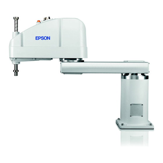
Page 31: Part Names And Outer Dimensions
Setup & Operation 2. Specifications 2.3 Part Names and Outer Dimensions G10-65***, G10-85*** manipulator of S/N: 1**** or later is different from other models NOTE in its form. For the detail, refer to Setup & Operation 2.3.4 G10-65***, G10-85***: For S/N: 1**** or later. - Page 32 Setup & Operation 2. Specifications (Mount eyebolt at shipment) G10-65*S G10/G20-85*S G20-A0*S G10/G20-**1S G10/G20-**4S 813.5 1053.5 213.5 −26.5 (*) indicates the stroke margin by mechanical stop. 90 or more Space for cables 1 mm flat cut Conical hole ø4,90° Max.ø18 through hole ø25 h7 shaft diameter Root both side chamfer C0.5 ø39.5 mechanical stop diameter...
- Page 33 Setup & Operation 2. Specifications Cleanroom-model G10/G20-***C The following figure shows the additional parts and specifications for the Table Top mounting Cleanroom-model when compared with the Standard-model in appearance. Upper bellows Plate cover (For static electricity countermeasure) Lower bellows Cover Plate cover for Table Top mounting surface (For static electricity...
- Page 34 Setup & Operation 2. Specifications (Mount eyebolt at shipment) G10-65*C G10/G20-85*C G20-A0*C G10/G20-**1C G10/G20-**4C 870.5 1129.5 205.5 −34.5 * indicates the stroke margin by mechanical stop. 90 or more Space for cables 1 mm flat cut Conical hole ø4,90° Max. ø18 through hole Root both side chamfer C0.5 ø25 h7 shaft diameter ø39.5 mechanical stop diameter...
- Page 35 Setup & Operation 2. Specifications Protected-model G10/G20-***D, P The following figure shows the additional parts and specifications for the Table Top mounting Protected-model when compared with the Standard-model in appearance. Normal G10/G20-***D* Manipulators do not have bellows. If necessary, select the bellows option at shipment.
- Page 36 Setup & Operation 2. Specifications (Mount eyebolt at shipment) G10-65*P G10/G20-85*P G20-A0*P G10/G20-**1P G10/G20-**4P 1133 205.5 −34.5 (*) indicates the stroke margin by mechanical stop. 90 or more Space for cables 1 mm flat cut Conical hole ø4,90° Max.ø18 through hole ø25 h7 shaft diameter Root both side chamfer C0.5 ø39.5 mechanical stop diameter...
-
Page 37: Wall Mounting
Setup & Operation 2. Specifications 2.3.2 Wall Mounting Standard-model G10/G20-***SW Joint #2 (rotating) Signature label − Joint #3 and #4 (Serial No. of Manipulator) brake release switch CE label UR label LED lamp Base Arm #1 − Joint #1 (rotating) Arm #2 Joint #3 (up and down) - Page 38 Setup & Operation 2. Specifications (*) indicates the stroke margin by mechanical stop. Detail of “B” 1 mm flat cut Conical hole ø4,90° 90 or more Space for cables Max.ø18 through hole ø25 h7 shaft diameter ø39.5 mechanical stop diameter Detail of “A”...
- Page 39 Setup & Operation 2. Specifications Cleanroom-model G10/G20-***CW The following figure shows the additional parts and specifications for the Wall mounting Cleanroom-model when compared with the Standard-model in appearance. Upper bellows Plate cover (For static electricity countermeasure) Lower bellows Plate cover (For static electricity countermeasure) Exhaust port...
- Page 40 Setup & Operation 2. Specifications (*) indicates the stroke margin by mechanical stop. Detail of “B” 90 or more 1 mm flat cut Space for cables Conical hole ø4,90° Max.ø18 through hole ø25 h7 shaft diameter ø39.5 mechanical stop diameter Detail of “A”...
- Page 41 Setup & Operation 2. Specifications Protected-model G10/G20-***DW, PW The following figure shows the additional parts and specifications for the Wall mounting Protected-model when compared with the Standard-model in appearance. Normal G10/G20-***DW Manipulators do not have bellows. If necessary, select the bellows option at shipment.
- Page 42 Setup & Operation 2. Specifications (*) indicates the stroke margin by mechanical stop. Detail of “B” 1 mm flat cut 90 or more Conical hole ø4,90° Space for cables Max.ø18 through hole ø25 h7 shaft diameter ø39.5 mechanical stop diameter Detail of “A”...
-
Page 43: Ceiling Mounting
Setup & Operation 2. Specifications 2.3.3 Ceiling Mounting Standard-model G10/G20-***SR Joint #2 (rotating) Joint #3 and #4 − brake release switch LED lamp Base Arm #1 − Joint #1 (rotating) Arm #2 Joint #3 Fitting (black or blue)* (up and down) for ø... - Page 44 Setup & Operation 2. Specifications (Tolerance applies to the pin hole) G10-65*SR G10/G20-85*SR G20-A0*SR G10/G20-**1SR G10/G20-**4SR −27.5 212.5 90 or more Space for cables (*) indicates the stroke margin by mechanical stop. 1 mm flat cut Conical hole ø4,90° Max.ø18 through hole ø25 h7 shaft diameter Detail of “B”...
- Page 45 Setup & Operation 2. Specifications Cleanroom-model G10/G20-***CR The following figure shows the additional parts and specifications for the Ceiling mounting Cleanroom-model when compared with the Standard-model in appearance. Cover for Ceiling mounting surface Upper bellows Plate cover (For static electricity countermeasure) Lower bellows Plate cover...
- Page 46 Setup & Operation 2. Specifications (Tolerance applies to the pin hole) G10-65*CR G10/G20-85*CR G20-A0*CR G10/G20-**1CR G10/G20-**4CR 29.5 288.5 90 or more Space for cables (*) indicates the stroke margin by mechanical stop. 1 mm flat cut Conical hole ø4,90° Max.ø18 through hole Detail of “B”...
- Page 47 Setup & Operation 2. Specifications Protected-model G10/G20-***DR, PR The following figure shows the additional parts and specifications for the Ceiling mounting Protected-model when compared with the Standard-model in appearance. Normal G10/G20-***DR Manipulators do not have bellows. If necessary, select the bellows option at shipment.
- Page 48 Setup & Operation 2. Specifications (Tolerance applies to the pin hole) G10-65*PR G10/G20-85*PR G20-A0*PR G10/G20-**1PR G10/G20-**4PR 518.5 777.5 90 or more Space for cables (*) indicates the stroke margin by mechanical stop. 1 mm flat cut Conical hole ø4,90° Detail of “B” Max.ø18 through hole ø25 h7 shaft diameter ø39.5 mechanical stop diameter...
-
Page 49: G10-65***/G10-85***: For S/N1**** Or Later
Setup & Operation 2. Specifications 2.3.4 G10-65***, G10-85***: For S/N: 1**** or later G10-65***, G10-85*** manipulator of S/N: 1**** or later is different from other models in its form. The additional screw holes processed on G10-85*** are not for the end effector or other equipments. -
Page 50: Specifications
Setup & Operation 2. Specifications 2.4 Specifications Item G10/G20-**** G10/G20-****R G10/G20-*****W Mount method Table Top Ceiling Wall Environment Cleanroom-model + ESD *1 / Protected-model *2 650 mm (G10 only) Arm #1, #2 850 mm (G10/G20) 1000 mm (G20 only) Arm length 180 mm : G10/G20-**1S*, D* 150 mm : G10/G20-**1C*, P*, D* with bellows option Arm #3... - Page 51 Setup & Operation 2. Specifications *a : The Joint #2 values for the following manipulators Max. motion range Max. pulse range G10/G20-85C, P, D with bellows option (Z: 360 to 390 only) G10/G20-85CW, PW, DW with bellows option ±151 deg ±2748871 G10/G20-85CR, PR, DR with bellows option Item...
- Page 52 Setup & Operation 2. Specifications Cleanliness level: Class ISO 3 (ISO14644-1) Amount of Dust (0.1 µm diameter or larger) in 28317 cm (1cft) sample-air around the center of the motion rang: 10 particles or less.) Exhaust System: Exhaust port diameter : Inner diameter: ø12 mm / Outer diameter: ø16 mm Exhaust tube : Polyurethane tube Outer diameter: ø12 mm (Inner diameter:ø8 mm)
-
Page 53: How To Set The Model
The custom specifications may require a different configuration procedure; check the custom specifications number (MT***) and contact us when necessary. The Manipulator model can be set from software. Refer to the chapter Robot Configuration in the EPSON RC+ User’s Guide. G10 / G20 Rev.20... -
Page 54: Environments And Installation
Setup & Operation 3. Environments and Installation 3. Environments and Installation 3.1 Environmental Conditions A suitable environment is necessary for the robot system to function properly and safely. Be sure to install the robot system in an environment that meets the following conditions: Item Conditions Ambient temperature... - Page 55 Setup & Operation 3. Environments and Installation Special Environmental Conditions The protective seals are attached on the Protected-model Manipulator to prevent dust, water, etc. from the outside. Follow the precautions in use environment described below: The surface of the Manipulator has general oil resistance. However, if your requirements specify that the Manipulator must withstand certain kinds of oil, please consult your distributor.
-
Page 56: Base Table
Setup & Operation 3. Environments and Installation 3.2 Base Table A base table for anchoring the Manipulator is not supplied. Please make or obtain the base table for your Manipulator. The shape and size of the base table differs depending on the use of the robot system. - Page 57 For environmental conditions regarding space when placing the Controller on the base table, refer to the Controller manual. ■ To ensure safety, a safeguard must be installed for the robot system. For details on the safeguard, refer to the EPSON RC+ User’s Guide. WARNING G10 / G20 Rev.20...
-
Page 58: Mounting Dimensions
Setup & Operation 3. Environments and Installation 3.3 Mounting Dimensions The maximum space described in figures shows that the radius of the end effector is 60 mm or less. If the radius of the end effector exceeds 60 mm, define the radius as the distance to the outer edge of maximum space. - Page 59 Setup & Operation 3. Environments and Installation G20-A0** Table Top Mounting G10/G20-85** Center of Joint #3 G10-65** Maximum space **** : G10/G20-85*S : 207.8 G10/G20-85*C : 218.3 G10/G20-85* G10-65** G20-A0** S, D C, P, D bellows a Length of Arm #1 (mm) b Length of Arm #2 (mm) Z: 0 to −360 207.8...
- Page 60 Setup & Operation 3. Environments and Installation G20-A0**W Wall Mounting G10/G20-85**W Center of Joint #3 G10-65**W Maximum space G10/G20-85* G10-65**W G20-A0**W CW, PW, DW SW, DW bellows a Length of Arm #1 (mm) b Length of Arm #2 (mm) c (Motion range) 306.5 207.8 218.3...
-
Page 61: Unpacking And Transportation
Setup & Operation 3. Environments and Installation 3.4 Unpacking and Transportation 3.4.1 Precautions for Transportation THE INSTALLATION SHALL BE PREFORMED BY QUALIFIED INSTALLATION PERSONNEL AND SHOULD CONFORM TO ALL NATIONAL AND LOCAL CODES. ■ Only authorized personnel should perform sling work and operate a crane and a forklift. -
Page 62: Transportation
Setup & Operation 3. Environments and Installation 3.4.2 Transportation Transport the Manipulator following the instructions below: (1) Attach the eyebolts to the upper back side of the Arm. (2) Pass the belts through the eyebolts. (3) Hoist the Manipulator slightly so that it does not fall. Then, remove the bolts securing the Manipulator to the delivery equipment or pallet. - Page 63 Setup & Operation 3. Environments and Installation 3.5.1 Table Top Mounting ■ Install the Table Top Mounting Manipulator with four or more people. The Manipulator weights are as follows. Be careful not to get hands, fingers, or feet caught and/or have equipment damaged by a fall of the Manipulator. G10-65** : Approximately 46 kg :102 lb.
-
Page 64: Wall Mounting
Setup & Operation 3. Environments and Installation 3.5.2 Wall Mounting ■ Install the Wall Mounting Manipulator with four or more people. The Manipulator weights are as follows. Be careful not to get hands, fingers, or feet caught and/or have equipment damaged by a fall of the Manipulator. G10-65**W : Approximately 51 kg :113 lb. -
Page 65: Ceiling Mounting
Setup & Operation 3. Environments and Installation 3.5.3 Ceiling Mounting ■ Install the Ceiling Mounting Manipulator with four or more people. The Manipulator weights are as follows. Be careful not to get hands, fingers, or feet caught and/or have equipment damaged by a fall of the Manipulator. G10-65**R : Approximately 46 kg :102 lb. -
Page 66: Cleanroom-Model
Setup & Operation 3. Environments and Installation 3.5.4 Cleanroom-model Unpack it outside of the clean room. Secure the Manipulator to delivery equipment such as a pallet with bolts so that the Manipulator does not fall. Wipe off the dust on the Manipulator with a little alcohol or distilled water on a lint-free cloth. -
Page 67: Connecting The Cables
Setup & Operation 3. Environments and Installation 3.6 Connecting the Cables ■ To shut off power to the robot system, disconnect the power plug from the power source. Be sure to connect the AC power cable to a power receptacle. DO NOT connect it directly to a factory power source. - Page 68 Setup & Operation 3. Environments and Installation Cable Connections Connect the power connector and signal connector of the M/C cables to the Controller. Power Connector Signal Connector G10 / G20 Rev.20...
-
Page 69: User Wires And Pneumatic Tubes
Setup & Operation 3. Environments and Installation 3.7 User Wires and Pneumatic Tubes ■ Only authorized or certified personnel should be allowed to perform wiring. Wiring by unauthorized or uncertified personnel may result in bodily injury and/or malfunction of the robot system. CAUTION User electrical wires and pneumatic tubes are contained in the cable unit. - Page 70 Setup & Operation 3. Environments and Installation Table Top Mounting User connector (9-pin D-sub connector) User connector (15-pin D-sub connector) Fitting (white) for ø6 mm pneumatic tube Fitting (black or blue)* for ø6 mm pneumatic tube Fitting (white) Fitting (black or blue)* for ø4 mm pneumatic tube for ø4 mm pneumatic tube Wall Mounting...
-
Page 71: Relocation And Storage
Setup & Operation 3. Environments and Installation 3.8 Relocation and Storage 3.8.1 Precautions for Relocation and Storage Observe the following when relocating, storing, and transporting the Manipulators. THE INSTALLATION SHALL BE PERFORMED BY QUALIFIED INSTALLATION PERSONNEL AND SHOULD CONFORM TO ALL NATIONAL AND LOCAL CODES. - Page 72 Setup & Operation 3. Environments and Installation 3.8.2 Table Top Mounting ■ Install or relocate the Table Top Mounting Manipulator with four or more people. The Manipulator weights are as follows. Be careful not to get hands, fingers, or feet caught and/or have equipment damaged by a fall of the Manipulator. G10-65** : Approximately 46 kg :102 lb.
-
Page 73: Wall Mounting
Setup & Operation 3. Environments and Installation 3.8.3 Wall Mounting ■ Install or relocate the Wall Mounting Manipulator with four or more people. The Manipulator weights are as follows. Be careful not to get hands, fingers, or feet caught and/or have equipment damaged by a fall of the Manipulator. G10-65**W : Approximately 51 kg :113 lb. -
Page 74: Ceiling Mounting
Setup & Operation 3. Environments and Installation 3.8.4 Ceiling Mounting ■ Install or relocate the Ceiling Mounting Manipulator with four or more people. The Manipulator weights are as follows. Be careful not to get hands, fingers, or feet caught and/or have equipment damaged by a fall of the Manipulator. G10-65**R : Approximately 46 kg :102 lb. -
Page 75: Setting Of End Effectors
Setup & Operation 4. Setting of End Effectors 4. Setting of End Effectors 4.1 Attaching an End Effector Users are responsible for making their own end effector(s). Before attaching an end effector, observe these guidelines. ■ If you use an end effector equipped with a gripper or chuck, connect wires and/or pneumatic tubes properly so that the gripper does not release the work piece when the power to the robot system is turned OFF. - Page 76 Setup & Operation 4. Setting of End Effectors Layouts - When you operate the manipulator with an end effector, the end effector may interfere with the Manipulator because of the outer diameter of the end effector, the size of the work piece, or the position of the arms.
-
Page 77: Attaching Cameras And Valves
Setup & Operation 4. Setting of End Effectors 4.2 Attaching Cameras and Valves Arm #2 has threaded holes as shown in the figure below. Use these holes for attaching cameras, valves, and other equipment. [Unit: mm] Common Dimensions 37.5 43.5 4-M4 depth 8 4-M4 depth 8 2-M4 depth 8... -
Page 78: Weight And Inertia Settings
Manipulator, and/or shorten the life cycle of parts/mechanisms. The acceptable weight capacity (end effector and work piece) in G10 series and G20 series Manipulators are as follows. - Page 79 Setup & Operation 4. Setting of End Effectors Load on the Arm When you attach a camera or other devices to the arm, calculate the weight as the equivalent of the shaft. Then, add this to the load and enter the total weight to the Weight parameter.
- Page 80 (5 kg) as 100%. G10-65*** G10-85*** (kg) Weight setting G20 series * The percentage in the graph is based on the speed at rated weight (10 kg) as 100%. (kg) Weight setting...
- Page 81 / deceleration at rated weight (5 kg) as 100%. G10-65*** G10-85*** (kg) Weight setting G20 series * The percentage in the graph is based on the acceleration / deceleration at rated weight (10 kg) as 100%. G20-85*** G20-A0***...
-
Page 82: Inertia Setting
Setting a value that is smaller than the actual moment of inertia may cause errors, excessive shock, insufficient function of the Manipulator, and/or shorten the life cycle of parts/mechanisms. The acceptable moment of inertia of load for a G10 series and G20 series Manipulators are as follows. Rated Max. - Page 83 Manager]). (You may also execute the Inertia command from the [Command Window].) Automatic acceleration/deceleration setting of Joint #4 by Inertia (moment of inertia) G10 series 0.05 0.10 0.15 0.20 0.25 (kg・m Moment of inertia setting G20 series 0.10 0.20 0.30 0.40 0.50 (kg・m Moment of inertia setting G10 / G20 Rev.20...
- Page 84 Manipulator, and/or shorten the life cycle of parts/mechanisms. The acceptable eccentric quantity of load in G10 series and G20 series Manipulators is 0 mm at the default rating and 200 mm at the maximum. When the eccentric quantity of load exceeds the rating, change the setting of eccentric quantity parameter of Inertia command.
- Page 85 EPSON Manager]). (You may also execute the Inertia command from the [Command Window].) Automatic acceleration/deceleration setting by Inertia (eccentric quantity) G10 series and G20 series * The percentage in the graph is based on the acceleration / deceleration at rated eccentricity (0 mm) as 100%.
- Page 86 Setup & Operation 4. Setting of End Effectors The methods for calculating the moment of inertia for (a), (b), and (c) are shown below. Calculate the total moment of inertia using the basic formulas. (a) Moment of inertia of a rectangular parallelepiped Rotation center Rectangular parallelepiped’s center of gravity Mass (m)
-
Page 87: Precautions For Auto Acceleration/Deceleration Of Joint #3
The upper limit of Joint #3 during horizontal motion using Jump command can be set by the LimZ command. Automatic acceleration/deceleration vs. Joint #3 position G10 series and G20 series * The percentage in the graph is based on the acceleration / deceleration at the upper-limited position of Joint #3 as 100%. -
Page 88: Motion Range
Setup & Operation 5. Motion Range 5. Motion Range ■ When setting up the motion range for safety, both the pulse range and mechanical stops must always be set at the same time. CAUTION The motion range is preset at the factory as explained in Setup & Operation: 5.4 Standard Motion Range. -
Page 89: Motion Range Setting By Pulse Range (For All Joints)
Manipulator does not move. The pulse range can be set on the [Range] panel shown by selecting [Tools]-[Robot EPSON Manager]. (You may also execute the Range command from the [Command Window].) 5.1.1 Max. Pulse Range of Joint #1 The 0 (zero) pulse position of Joint #1 is the position where Arm #1 faces toward the positive (+) direction on the X-coordinate axis. -
Page 90: Max. Pulse Range Of Joint #2
Setup & Operation 5. Motion Range 5.1.2 Max. Pulse Range of Joint #2 The 0 (zero) pulse position of Joint #2 is the position where Arm #2 is in-line with Arm #1. With the 0 pulse as a starting point, the counterclockwise pulse value is defined as the positive (+) and the clockwise pulse value is defined as the negative (-). -
Page 91: Max. Pulse Range Of Joint #3
Setup & Operation 5. Motion Range 5.1.3 Max. Pulse Range of Joint #3 The 0 (zero) pulse position of Joint #3 is the position where the shaft is at its upper limit. The pulse value is always negative because Joint #3 always moves lower than the 0 pulse position. -
Page 92: Motion Range Setting By Mechanical Stops
Setup & Operation 5. Motion Range 5.2 Motion Range Setting by Mechanical Stops Mechanical stops physically limit the absolute area that the Manipulator can move. Both Joints #1 and #2 have threaded holes in the positions corresponding to the angle for the mechanical stop settings. -
Page 93: Setting The Mechanical Stops Of Joints #1 And #2
Setup & Operation 5. Motion Range 5.2.1 Setting the Mechanical Stops of Joints #1 and #2 Both Joints #1 and #2 have threaded holes in the positions corresponding to the angle for the mechanical stop settings. Install the bolts in the holes corresponding to the angle that you want to set. - Page 94 Setup & Operation 5. Motion Range Joint #2 Mechanical Stops Joint #2 Model Arm Length Table Top, Ceiling, Wall -152.5° -122.5° +122.5° +152.5° G10/G20-85*S, D Z: 0 to –360 Table Top G10/G20-85*C, P, D bellows Z: –360 to –390 +121° +151°...
- Page 95 The angle of Joint #1 is set from –105 degrees to +105 degrees. The angle of Joint #2 is set from –122.5 degrees to +122.5 degrees. Execute the following commands from the [Command Window]. EPSON >JRANGE 1,-436907,5679787 ' Sets the pulse range of Joint #1 >JRANGE 2,-2230045,2230045 ' Sets the pulse range of Joint #2...
-
Page 96: Setting The Mechanical Stop Of Joint #3
Setup & Operation 5. Motion Range In this example, Joint #1 is moved to the center of its motion range (pulse value: 2621440) when checking Joint #2. If the arm is hitting the mechanical stops or if an error occurs after the arm hits the mechanical stops, either reset the pulse range to a narrower setting or extend the positions of the mechanical stops within the limit. - Page 97 When lowering the mechanical stop by 80 mm and changing the lower limit Z coordinate value to “-100” in 180 mm stroke (−100)/25×131072×(66/32) = −1081344 Execute the following command from the [Command Window]. EPSON >JRANGE 3,-1081344,0 ' Sets the pulse range of Joint #3 Example: When lowering the mechanical stop by 320 mm and changing the lower limit Z coordinate value to “-100”...
-
Page 98: Setting The Cartesian (Rectangular) Range In The Xy Coordinate System Of The Manipulator (For Joints #1 And #2)
When lowering the mechanical stop by 80 mm and changing the lower limit Z coordinate value to “-100” in 180 mm stroke Execute the following commands from the [Command Window]. EPSON >MOTOR ON ' Turns ON the motor >SPEED 5 ' Sets low speed >PULSE 0,0,-1081344,0 ' Moves to the lower limit-pulse position of Joint #3. -
Page 99: Standard Motion Range
Setup & Operation 5. Motion Range 5.4 Standard Motion Range The following “motion range” diagrams show the standard (maximum) specification. When each Joint motor is under servo control, the center of Joint #3’s (shaft’s) lowest point moves in the areas shown in the figure. “Area limited by mechanical stop”... - Page 100 Setup & Operation 5. Motion Range Wall Mounting G20-A0**W G10/G20-85**W Center of Joint #3 G10-65**W Maximum space Motion range Area limited by mechanical stop Center of base reference hole (°: degree) G10-65**W 130° 291.2 306.5 650 473.1 485.5 133.5 231.2 3.5°...
- Page 101 Setup & Operation 5. Motion Range Ceiling Mounting G10-A0**R G10/G20-85**R Center of Joint #3 Maximum space G10-65**R Motion range Area limited by mechanical stop Base mounting face (°: degree) G10-65**R 107° 130° 291.2 306.5 650 473.1 485.5 133.5 231.2 3.5° G10/G20-85*SR, DR 152.5°...
- Page 102 Setup & Operation 5. Motion Range G10 / G20 Rev.20...
-
Page 103: Maintenance
Maintenance This volume contains maintenance procedures with safety precautions for G10/G20 series Manipulators. -
Page 105: Safety Maintenance
Maintenance 1. Safety Maintenance 1. Safety Maintenance Please read this chapter, this manual, and other relevant manuals carefully to understand safe maintenance procedures before performing any routine maintenance. Only authorized personnel who have taken safety training should be allowed to maintain the robot system. -
Page 106: General Maintenance
Maintenance 2. General Maintenance ■ Be sure to connect the cables properly. Do not allow unnecessary strain on the cables. (Do not put heavy objects on the cables. Do not bend or pull the cables forcibly.) The unnecessary strain on the cables may result in damage to the cables, disconnection, and/or contact failure. -
Page 107: Inspection Point
Maintenance 2. General Maintenance 2.1.2 Inspection Point Inspection While the Power is OFF (Manipulator is not operating) Inspection Point Inspection Place Daily Monthly Quarterly Biannual Annual End effector mounting bolts √ √ √ √ √ Check looseness or backlash of Manipulator mounting bolts √... -
Page 108: Overhaul (Parts Replacement)
EPSON RC+ 7.0. For details, refer to the following manual. Robot Controller RC700 / RC700-A Maintenance 6. Alarm For the EPSON RC+ 5.0 Ver. 5.4.7 or later (firmware Ver.1.16.4.x or 1.24.4.x or later), the NOTE recommended replacement time for the parts subject to maintenance (motors, reduction gear units, and timing belts) can be checked in the [Maintenance] dialog box of the EPSON RC+ 5.0. - Page 109 (3) Select the folder where the information is stored. (4) Click <OK> to view the [Controller Status Viewer] dialog. (5) Select [Robot] from the tree menu on the left side (Dialog image: EPSON RC+ 7.0) For the parts subject to overhaul, refer to Maintenance 15. Maintenance Parts List.
-
Page 110: Greasing
Maintenance 2. General Maintenance 2.3 Greasing The ball screw spline and reduction gear units need greasing regularly. Only use the grease specified in the following table. ■ Keep enough grease in the Manipulator. Operating the Manipulator with insufficient grease will damage sliding parts and/or result in insufficient function of the Manipulator. - Page 111 [Maintenance] dialog box of the EPSON RC+ 7.0. For details, refer to the following manual. Robot Controller RC700 / RC700-A Maintenance 6. Alarm For the EPSON RC+ 5.0 Ver. 5.4.7 or later (firmware Ver.1.16.4.x or 1.24.4.x or later), the NOTE ...
-
Page 112: Tightening Hexagon Socket Head Cap Bolts
Then, follow the steps below to display the pulse values and record them. Execute the following command from the [Command Window]. EPSON >PULSE PULSE: [Joint #1 Pulse value] pls [Joint #2 Pulse value] pls [Joint #3 Pulse value] pls [Joint #4 Pulse value] pls G10 / G20 Rev.20... -
Page 113: Layout Of Maintenance Parts
Maintenance 2. General Maintenance 2.6 Layout of Maintenance Parts G10-65*** manipulator of S/N: 1**** or later is different from other models in its maintenance parts position. For the detail, refer to Setup & Operation 2.6.4 G10-65***: For S/N: 1**** or later. 2.6.1 Table Top Mounting type G10-***S : Standard-model LED lamp... - Page 114 Maintenance 2. General Maintenance G20-***S : Standard-model LED lamp Brake release switch Joint #4 motor Arm cover Ball screw spline unit Joint #2 motor Joint #3 motor Joint #2 reduction gear unit Cable unit Z belt Joint #4 reduction gear unit Lithium battery and Battery board Power cable U belt...
-
Page 115: Wall Mounting Type
Maintenance 2. General Maintenance 2.6.2 Wall Mounting type G10-***SW : Standard-model Power cable LED lamp Brake release switch Signal cable Ball screw spline unit Arm cover Joint #4 motor Joint #4 brake Joint #1 motor Joint #1 Z belt reduction gear unit U belt Joint #2 motor Cable unit... - Page 116 Maintenance 2. General Maintenance G20-***SW : Standard-model Brake release switch Power cable LED lamp Joint #4 motor Signal cable Arm cover Ball screw spline unit Joint #3 motor Joint #1 motor Z belt Joint #1 reduction gear unit Joint #2 motor Cable unit Lithium battery and Battery board Joint #2 reduction gear unit...
-
Page 117: Ceiling Mounting Type
Maintenance 2. General Maintenance 2.6.3 Ceiling Mounting type G10-***SR : Standard-model LED lamp Brake release switch Power cable Arm cover Ball screw spline unit Signal cable Joint #4 motor Joint #1 motor Joint #4 brake Joint #1 Z belt reduction gear unit U belt Joint #2 motor Cable unit... - Page 118 Maintenance 2. General Maintenance G20-***SR : Standard-model Brake release switch LED lamp Joint #4 motor Power cable Arm cover Ball screw spline unit Signal cable Joint #3 motor Joint #1 motor Z belt Joint #1 reduction gear unit Joint #2 motor Cable unit Lithium battery and Battery board Joint #2 reduction gear unit...
-
Page 119: G10-65***: For S/N1**** Or Later
Maintenance 2. General Maintenance 2.6.4 G10-65***: For S/N: 1**** or later The following maintenance parts have been added for G10-65*** manipulator of S/N: 1**** or later. Standard model G10-65*S* Radiating unit Heat sink Cleanroom model G10-65*C* Radiating unit Heat sink Protection model G10-65*P* Radiating unit... -
Page 120: Covers
Maintenance 3. Covers 3. Covers All procedures for removing and installing covers in maintenance are described in this chapter. ■ Do not connect or disconnect the motor connectors while the power to the robot system is turned ON. Connecting or disconnecting the motor connectors with the power ON is extremely hazardous and may result in serious bodily injury as the Manipulator may move abnormally, and also may result in electric shock and/or malfunction of the robot system. - Page 121 Maintenance 3. Covers Table Top mounting Arm top cover Side cover Arm cap Arm cap Side cover Arm bottom cover Connector plate Connector sub plate Maintenance plate Base bottom cover (Except G10/G20-***S) Wall mounting Ceiling mounting Base bottom cover Connector sub plate (Except G10/G20-***SR) Connector plate Maintenance plate...
-
Page 122: Arm Top Cover
Maintenance 3. Covers 3.1 Arm Top Cover ■ Do not remove the arm top cover forcibly. Removing the cover forcibly may result in damage to the cables, disconnection, and/or contact failure. Damaged cables, disconnection, or contact failure is extremely hazardous and may result in electric shock and/or improper function of the robot system. - Page 123 Maintenance 3. Covers G10-***S* G10-***C* (Cleanroom-model) (Standard-model) G10-***D*/P* (Protected-model) 4-M4×15 4-M4×15 Gasket (G10-***P* only) Gaskets (G10-***P* only) O-ring (G10-***D*/P*) Gaskets are installed to G10-***P*. O-ring is installed to G10-***D*, P*. G20-***S* G20-***C* (Cleanroom-model) (Standard-model) G20-***D*/P* (Protected-model) 4-M4×15 4-M4×15 Gasket (G20-***P* only) Gasket (G20-***P* only) Gaskets are installed to G20-***P*.
-
Page 124: Arm Bottom Cover
Maintenance 3. Covers 3.2 Arm Bottom Cover Unscrew the arm bottom cover mounting bolts, and then pull the cover downward and remove it. The arm bottom cover may not be removed from the shaft because the end effector is NOTE ... -
Page 125: Arm #1 Cover
Maintenance 3. Covers 3.3 Arm #1 Cover There are two sets of Arm #1 covers. - Arm caps - Side covers Unscrew the bolts mounting the covers and the caps to remove them. 3.3.1 G10/G20-***S* (Standard-model), G10/G20-***C* (Cleanroom-model) Arm side (Common part) Base side Table Top mounting For the arm cap... -
Page 126: G10/G20-***D*, P
Maintenance 3. Covers 3.3.2 G10/G20-***D*, P* (Protected-model) Arm side (Common part) Base side Table Top mounting For the arm cap : 4-M4×8 Gaskets Sealing washer Gasket Gasket For the side cover Sealing washer : 4-M4×15 For the side cover For the arm cap : 4-M4×15 : 4-M4×8 Wall mounting... -
Page 127: Connector Plate
Maintenance 3. Covers 3.4 Connector Plate ■ Do not remove the connector plate forcibly. Removing the connector plate forcibly may result in damage to the cables, disconnection, and/or contact failure. Damaged cables, disconnection, or contact failure is extremely hazardous and may result in electric shock and/or improper function of the robot system. -
Page 128: Connector Sub Plate
Maintenance 3. Covers 3.5 Connector Sub Plate ■ Do not remove the connector sub plate forcibly. Removing the connector sub plate forcibly may result in damage to the cables, disconnection, and/or contact failure. Damaged cables, disconnection, or contact failure is extremely hazardous and may result in electric shock and/or improper function of the robot system. -
Page 129: User Plate
Maintenance 3. Covers 3.6 User Plate Unscrew the user plate mounting bolts and remove the plate. NOTE Do not remove the nut by force. The nut for the user plate is combined with the user plate. And if you try to remove the nut, it will damage the user plate. G10/G20-***S* (Standard-model) G10/G20-***C* (Cleanroom-model) G10/G20-***D*, P* (Protected-model) -
Page 130: Base Bottom Cover
Maintenance 3. Covers 3.8 Base Bottom Cover The base bottom cover is removed only when replacing the gasket unit. Unscrew the base bottom cover mounting bolts and remove the cover. G10/G20-***C* (Cleanroom-model) G10/G20-***D*, P* (Protected-model) Table Top mounting Gasket 8-M3×8 8-M3×8 Ceiling mounting... -
Page 131: Cable
Maintenance 4. Cable 4. Cable ■ Do not connect or disconnect the motor connectors while the power to the robot system is turned ON. Connecting or disconnecting the motor connectors with the power ON is extremely hazardous and may result in serious bodily injury as the Manipulator may move abnormally, and also may result in electric shock and/or malfunction of the robot system. -
Page 132: Replacing Cable Unit
Controller is turned OFF. When the battery connectors are disconnected, the position data will be lost, and EPSON RC+ will display an error when the Controller is turned ON. If the error occurs, execute the calibration of all joints and axes. - Page 133 Maintenance 4. Cable G10-65*** manipulator of S/N: 1**** or later is different from other models in its form. NOTE For the detail, refer to Setup & Operation 2.6.4 G10-65***: For S/N: 1**** or later. Table Top mounting Cable Unit Cable Unit Wall mounting Cable Unit...
- Page 134 Maintenance 4. Cable ■ If the connectors have been disconnected during the replacement of the cable unit, be sure to reconnect the connectors to their proper positions. Refer to the block diagrams. Improper connection of the connectors may result in improper function of the robot system.
- Page 135 Maintenance 4. Cable Cable unit (1) Turn ON the Controller and change the motor to OFF status (MOTOR OFF). Removal (2) Press and hold the brake release switch to let the shaft down. Be sure to keep enough space and prevent the end effector hitting any peripheral equipment. The brake release switch affects both Joints #3 and #4.
- Page 136 Maintenance 4. Cable (7)-2 Remove the spring plate. Spring plate 2-M4×15 Wire tie (7)-3 Cut the wire tie banding the cables. (7)-4 Pull out the spring plate. Spring plate (7)-5 Remove the saddle part mounting the 2-M4×10 cables. Saddle part (7)-6 Cut the wire tie banding the spring.
- Page 137 Maintenance 4. Cable (12) Cut off the wire tie binding Wire ties Wire ties cables on the Arm #2 side. (13) Remove the 11 connectors on the Arm side. X21, X22, X31, X32, X33, X41, X42, X61, X221, X231, X241 Be sure to keep the connectors excluding X61 of the battery board connected at NOTE ...
- Page 138 Maintenance 4. Cable Table Top mounting (19) Disconnect the cables that were disconnected from Arm #1 in step (18) to the side of Arm #1. Cable Wall / Ceiling mounting Cable (20) Disconnect the Arm #2 side cables from the lower part of Arm #1.
- Page 139 Maintenance 4. Cable Applying positions Cable unit (1) Apply grease (GPL-224) to the cables. Each cable inside the spring Installation Grease volume: 5 g each (10 g in total) Air tube Periphery of spring (shaded part) Base side Arm side 200 mm 200 mm Greasing...
- Page 140 Maintenance 4. Cable (5) When using Table Top mounting, disconnect the Table Top mounting base side cables to the upper part of Arm #1 and Cable pull the cables into the base. When using Wall mounting or Ceiling mounting, Wall / Ceiling mounting disconnect the base side cables to the lower part of Arm #1 and pull the cables into the base.
- Page 141 Maintenance 4. Cable When using Wall mounting type (6)-1 Pull out the spring and mount it to the spring plate with a wire tie. (6)-2 Mount the saddle part to mount the 2-M4×10 cables. Saddle part Spring plate (6)-3 Loosely band the cables with a wire tie. Be sure to keep the wire tie loose enough so that the cables move.
- Page 142 Maintenance 4. Cable (7) Connect the air tubes, D-sub cable, and connectors to the connector plate (inner side). D-sub cable Spring washer Connector Plain washer Ground Air tube terminal Connector plate D-sub (8) Loosely mount the connector plate with 2 screws (M4). For details, refer to Maintenance: 3.4 Connector Plate.
- Page 143 Maintenance 4. Cable (13) Mount the saddle part to the spring plate. Saddle part 2-M4×10 (14) Connect the connectors and the ground wire. For details, refer to Maintenance: 4.2 Wiring Diagrams. (15) Bind the excess cables with a wire tie. D-sub cable (16) Connect the D-sub cable, air tubes, and connector of the brake release switch cable to the user plate.
-
Page 144: Wiring Diagrams
Maintenance 4. Cable 4.2 Wiring Diagrams 4.2.1 Signal Cable G10 / G20 Rev.20... -
Page 145: Power Cable
Maintenance 4. Cable 4.2.2 Power Cable RC180 G10 / G20 Rev.20... - Page 146 Maintenance 4. Cable RC700-A, RC700DU-A G10 / G20 Rev.20...
-
Page 147: User Cable
Maintenance 4. Cable 4.2.3 User Cable Code Cable color Code Cable color Black Brown Violet Green White Blue Yellow The following table shows the types of the use cable. Environment Arm length Code Note 650 mm R13B020033 850 mm R13B020018 1000 mm R13B020019 650 mm... -
Page 148: Replacing M/C Cable
Controller is turned OFF. When the battery connectors are disconnected, the position data will be lost, and EPSON RC+ will display an error when the Controller is turned ON. NOTE If the connector connected to the battery was disconnected during cable replacement, ... - Page 149 Maintenance 4. Cable G10-65*** manipulator of S/N: 1**** or later is different from other models in its form. NOTE For the detail, refer to Setup & Operation 2.6.4 G10-65***: For S/N: 1**** or later. Table Top mounting M/C Cable M/C Cable Wall mounting M/C Cable...
- Page 150 Maintenance 4. Cable M/C Cable (1) Turn OFF the Controller. Removal (2) Disconnect the power cable and signal cable connectors from the controller. (3) Remove the Connector Sub Plate. For details, refer to Maintenance: 3.5 Connector Sub Plate. NOTE Do not pull the Sub plate forcibly. ...
-
Page 151: Arm #1
Maintenance 5. Arm #1 5. Arm #1 ■ Do not connect or disconnect the motor connectors while the power to the robot system is turned ON. Connecting or disconnecting the motor connectors with the power ON is extremely hazardous and may result in serious bodily injury as the Manipulator may move abnormally, and also may result in electric shock and/or malfunction of the robot system. -
Page 152: Replacing Joint #1 Motor
Maintenance 5. Arm #1 5.1 Replacing Joint #1 Motor Name Quantity Note R13B000610 Maintenance AC Servo Motor (750 W) R13B000624 parts (For S/N: 1**** or later) width across flats: 2.5 mm For M5 set screw width across flats: 3 mm For M4 screw Hexagonal wrench width across flats: 4 mm... - Page 153 Maintenance 5. Arm #1 (1) Mount the motor flange on the Joint #1 motor. Joint #1 motor Installation Motor flange 4-M6×20 (2) Apply grease around the motor shaft. Grease volume: 28 g (3) Mount the waveform generator on the Joint #1 Wave generator M5 brass bushing motor.
-
Page 154: Replacing Joint #1 Reduction Gear Unit
Maintenance 5. Arm #1 5.2 Replacing Joint #1 Reduction Gear Unit A reduction gear unit consists of the following three parts and two attached parts. At replacing the reduction gear unit, be sure to always replace them all together as one set. Reduction gear unit : Waveform generator, Flexspline, Circular spline Attachment : Spacer, Grip ring... - Page 155 Maintenance 5. Arm #1 (1) Execute the removal steps from (1) to (5) in Maintenance: 5.1 Replacing Joint #1 Joint #1 reduction gear Motor and remove the waveform generator. unit (2) Remove the arm cap on the base side. Removal For details, refer to Maintenance: 3.3 Arm #1 Cover.
- Page 156 Maintenance 5. Arm #1 Joint #1 (1) A new reduction gear unit contains the parts shown reduction gear in the picture on the right when it is unpacked. unit Installation (2) Apply LOCTITE 241 on the screws. 16-M5×25 Set the hole on the circular spline and the tap hole on the base.
-
Page 157: Arm #2
Maintenance 6. Arm #2 6. Arm #2 ■ Do not connect or disconnect the motor connectors while the power to the robot system is turned ON. Connecting or disconnecting the motor connectors with the power ON is extremely hazardous and may result in serious bodily injury as the Manipulator may move abnormally, and also may result in electric shock and/or malfunction of the robot system. -
Page 158: Replacing Joint #2 Motor
Maintenance 6. Arm #2 6.1 Replacing Joint #2 Motor Name Quantity Note R13B000611 Maintenance AC Servo Motor (600W) R13B000623 Parts (For S/N: 1**** or later) width across flats: 2.5 mm For M5 set screw Hexagonal wrench width across flats: 3 mm For M4 screw width across flats: 4 mm For M5 screw... - Page 159 Maintenance 6. Arm #2 Joint #2 motor (1) Turn ON the Controller. Removal (2) Push down the shaft to its lower limit while pressing the brake release switch. Be sure to keep enough space and prevent the end effector hitting any peripheral equipment.
- Page 160 Maintenance 6. Arm #2 (9) Remove the Joint #2 motor unit from Arm #2. To do so, unscrew the bolts from the Joint #2 6-M4×15 motor flange. Pull the Joint #2 motor unit upward to remove. If the motor cannot be removed easily, pull it out while moving Arm #2 slowly by hand.
- Page 161 Maintenance 6. Arm #2 Joint #2 motor (1) Mount the motor flange on the Joint #2 motor. Installation Set the spring plate mounting hole of the motor flange in the counter direction to the motor cable. 4-M5×15 (2) Apply grease around the motor shaft. Grease volume: 28 g (3) Mount the waveform generator on the Joint #2 M5 bushing...
- Page 162 Maintenance 6. Arm #2 (6) Mount the spring plate. 2-M4×8 (7) Connect the connectors X221, X21, and X62. (8) Re-bundle the cables in their original positions Spring with a wire tie removed in the removal procedure plate step (5). Do not allow unnecessary strain on the cables. (9) Mount the arm top cover.
-
Page 163: Replacing Joint #2 Reduction Gear Unit
Maintenance 6. Arm #2 6.2 Replacing Joint #2 Reduction Gear Unit A reduction gear unit consists of the following three parts and one attached parts. At replacing the reduction gear unit, be sure to always replace them all together as one set. Reduction gear unit : Waveform generator, Flexspline, Circular spline Attachment : Spacer... - Page 164 Maintenance 6. Arm #2 Joint #2 (1) Turn ON the Controller. reduction gear (2) Push down the shaft to its lower limit while pressing the brake release switch. Be unit sure to keep enough space and prevent the end effector hitting any peripheral Removal equipment.
- Page 165 Maintenance 6. Arm #2 Joint #2 (1) A new reduction gear unit contains the parts reduction gear shown in the picture on the right when it is unit unpacked. Installation (2) Set the hole on the circular spline and the tap hole on the base.
-
Page 166: Arm #3
Maintenance 7. Arm #3 7. Arm #3 ■ Do not connect or disconnect the motor connectors while the power to the robot system is turned ON. Connecting or disconnecting the motor connectors with the power ON is extremely hazardous and may result in serious bodily injury as the Manipulator may move abnormally, and also may result in electric shock and/or malfunction of the robot system. -
Page 167: Replacing Joint #3 Motor
Maintenance 7. Arm #3 7.1 Replacing Joint #3 Motor Name Quantity Note R13B000607 Maintenance AC Servo Motor (400W) R13B000616 parts (For S/N: 1**** or later) width across flats: 2 mm For M4 set screw Hexagonal wrench width across flats: 3 mm For M4 screw width across flats: 4 mm For M5 screw... - Page 168 Maintenance 7. Arm #3 (7) When you use the plate of 4-point mounting, 4-point mounting remove the plate. 4-M4×10 When removing the battery unit mounting bolts, be sure to keep the connectors connected to the Plate battery unit. If connectors of the battery unity are Battery unit disconnected, you need to perform calibration again.
- Page 169 Maintenance 7. Arm #3 Joint #3 motor (1) Secure the pulley to the new motor shaft. M4 bushing Installation Be sure to fit the end face of the pulley to the Pulley end face of the motor shaft. 2-M4×5 set screw Tighten one of the set screws on the flat face of the motor shaft until the screw just touches the surface.
- Page 170 When you use the plate of 3-point mounting, mount the plate with pressing it to the motor Plate side*. Battery unit * G10 series: Joint #4 motor side G20 series: Joint #3 motor side 3-point mounting When mounting the battery unit mounting NOTE Battery...
-
Page 171: Replacing The Timing Belt
Maintenance 7. Arm #3 7.2 Replacing the Timing Belt The length and the replacement procedure of the timing belts for G10 series and G20 series are different. Name Quantity Note G10 : width 12 mm R13B030209 Maintenance Z belt G20 : width 12 mm R13B030211 parts width across flats: 1.5 mm... -
Page 172: G10
Maintenance 7. Arm #3 7.2.1 Replacing the Timing Belt : G10 A brake is mounted on the motor of Joints #3 and #4 to prevent the shaft from moving down due to the weight of the end effector while the power to the Controller is OFF or while the motor is in OFF status (MOTOR OFF). - Page 173 Maintenance 7. Arm #3 Z belt (1) Pass a new Z belt through the shaft from above, 3-M5×15 Installation : G10 and then place it under the spline plate. Z belt (2) Pass the belt through Arm #2. (3) Loosely secure the spline plate to Arm #2. After moving the shaft up and down several Spline plate times, secure the spline plate to Arm #2.
- Page 174 Maintenance 7. Arm #3 (9) Set the Joint #4 motor unit in Arm #2. 4-M4×15 Joint #4 + Washer motor unit Place the Joint #4 motor unit in Arm #2 so that the motor cable faces toward the left from the end of the arm.
- Page 175 Maintenance 7. Arm #3 (13) When you use the plate of 4-point mounting, 4-point mounting mount the plate. 4-M4×10 When you use the plate of 3-point mounting, mount the plate pressing it to the Joint #4 motor Plate side. Battery unit When mounting the battery unit, be sure to keep the connectors connected to the battery unit.
- Page 176 Maintenance 7. Arm #3 7.2.2 Replacing the Timing Belt : G20 A brake is mounted on the motor of Joints #3 and #4 to prevent the shaft from moving down due to the weight of the end effector while the power to the Controller is OFF or while the motor is in OFF status (MOTOR OFF).
-
Page 177: G20
Maintenance 7. Arm #3 7.3 Replacing the Brake Name Quantity Note R13B030503 Maintenance Solenoid brake parts width across flats: 1.5 mm For M3 set screw width across flats: 2.5 mm For M3 screw Hexagonal wrench width across flats: 3 mm For M4 screw Tools width across flats: 4 mm... - Page 178 Maintenance 7. Arm #3 Joint #3 brake (1) Mount the brake hub to the Z1 pulley. 2-M3×4 Installation Set screw Brake hub (2) Mount the brake support to the brake. Brake 3-M3×8 Brake support (3) Mount back the Joint #3 brake unit to Arm Brake unit The screws are not secured in this step.
-
Page 179: Arm #4
Maintenance 8. Arm #4 8. Arm #4 ■ Do not connect or disconnect the motor connectors while the power to the robot system is turned ON. Connecting or disconnecting the motor connectors with the power ON is extremely hazardous and may result in serious bodily injury as the Manipulator may move abnormally, and also may result in electric shock and/or malfunction of the robot system. -
Page 180: Replacing Joint #4 Motor
Maintenance 8. Arm #4 8.1 Replacing Joint #4 Motor The shape and the replacement procedure of the Joint #4 AC servo motor for G10 series and G20 series are different. Name Quantity Note R13B000612 150W R13B000618 (For S/N: 1**** or later) - Page 181 Maintenance 8. Arm #4 Joint #4 motor (1) Turn ON the Controller. Removal: G10 (2) Push down the shaft to its lower limit while pressing the brake release switch. Be sure to keep enough space and prevent the end effector hitting any peripheral equipment.
- Page 182 Maintenance 8. Arm #4 Joint #4 motor (1) Mount the U1 pulley and the motor plate to the Pulley Installation: G10 new Joint #4 motor. M4 bushing 2-M4×8 Pull the pulley to the motor side with 50N force to set screw pressurize the bearing while securing the pulley.
- Page 183 Maintenance 8. Arm #4 (6) When you use the plate of 3-point mounting, 3-point mounting mount the plate with pressing it to the Joint #4 motor. Be sure to keep the connectors connected to the NOTE Battery unit battery unit. If connectors of the battery unity are disconnected, Plate you need to perform calibration again.
-
Page 184: G20
Maintenance 8. Arm #4 8.1.2 Replacing the Joint #4 Motor: G20 A brake is mounted on the motor of Joints #3 and #4 to prevent the shaft from moving down due to the weight of the end effector while the power to the Controller is OFF or while the motor is in OFF status (MOTOR OFF). - Page 185 Maintenance 8. Arm #4 (1) Mount the ring to the Joint #4 motor. Joint #4 motor Ring Installation: G20 Bushing Be sure to fit the end face of the ring 16.5 mm from the end face of the motor shaft. 2-M3×8 set screw Tighten one of the set screws on the flat face of the...
-
Page 186: Replacing The Timing Belt
Maintenance 8. Arm #4 8.2 Replacing the Timing Belt The length and the replacement procedure of the timing belts for G10 series and G20 series are different. Name Quantity Note width 15 mm R13B030210 Maintenance U belt width 20 mm R13B030212 parts width across flats: 1.5 mm... - Page 187 Maintenance 8. Arm #4 8.2.1 Replacing the Timing Belt: G10 A brake is mounted on the motor of Joints #3 and #4 to prevent the shaft from moving down due to the weight of the end effector while the power to the Controller is OFF or while the motor is in OFF status (MOTOR OFF).
- Page 188 Maintenance 8. Arm #4 (7) Remove the Joint #4 motor unit from Arm #2. Joint #4 4-M4×15 motor unit + Washer Pull out the U belt from the U1 pulley to remove it. (8) Remove the brake hub. Brake hub 2-M3×4 set screw Loosen the two set screws and pull out the brake...
- Page 189 Maintenance 8. Arm #4 U belt (1) Hold the spline plate and place the U belt around the Spline plate Installation: G10 U2 pulley so that the gear grooves of the belt are fit U belt into those of the pulleys completely. (2) Place the Z belt around the Z1 pulley and the Z2 pulley so that the gear grooves of the belt are fit into Z belt...
- Page 190 Maintenance 8. Arm #4 (7) Apply the proper tension to the Z belt and U G10 : Z belt tension = 130 N (13.3 kgf) belt, and then secure the Joint #3 motor unit Joint #3 and Joint #4 motor unit. motor unit To do so, pass a suitable cord or string Force gauge...
-
Page 191: G20
Maintenance 8. Arm #4 8.2.2 Replacing the Timing Belt: G20 A brake is mounted on the motor of Joints #3 and #4 to prevent the shaft from moving down due to the weight of the end effector while the power to the Controller is OFF or while the motor is in OFF status (MOTOR OFF). - Page 192 Maintenance 8. Arm #4 (7) Remove the Joint #4 motor unit from Arm #2. Joint #4 4-M4×15 motor unit + Washer (8) Remove the Z belt from the Z pulley and remove the U belt U belt. 3-M5×15 Spline plate Remove the bolts securing the spline plate.
- Page 193 Maintenance 8. Arm #4 U belt (1) Hold the spline plate and place the U belt around the U belt Installation: G20 U2 pulley so that the gear grooves of the belt are fit 3-M5×15 Spline plate into those of the pulleys completely. (2) Place the Z belt around the Z1 pulley and the Z2 pulley so that the gear grooves of the belt are fit into Z belt...
- Page 194 Maintenance 8. Arm #4 (7) Apply the proper tension to the Z belt and U G20 : Z belt tension = 130 N (13.3 kgf) belt, and then secure the Joint #3 motor unit Joint #3 and Joint #4 motor unit. motor unit To do so, pass a suitable cord or string around Force gauge...
- Page 195 Maintenance 8. Arm #4 (8) When you use the plate of 3-point mounting, mount 4-point mounting the plate. 4-M4×10 Plate When you use the plate of 3-point mounting, mount the plate with pressing it to the Joint #3 motor. Battery unit When mounting the battery unit, be sure to keep the NOTE 3-point mounting...
-
Page 196: Replacing The Brake
Maintenance 8. Arm #4 8.3 Replacing the Brake The brake of Joint #4 for G20 series is built in the motor. Replace the motor to change the brake. Name Quantity Note R13B030501 Maintenance Solenoid brake parts width across flats: 1.5 mm... - Page 197 Maintenance 8. Arm #4 (7) When you use the plate of 3-point mounting, loosen 3-point mounting the plate mounting bolt. NOTE Be sure to keep the connectors connected to the Plate battery unit. If connectors of the battery unity are disconnected, you need to perform calibration again.
- Page 198 Maintenance 8. Arm #4 Joint #4 brake (1) Mount the brake. 2-M2.5×20 Brake Installation: G10 (2) Secure the brake hub with the two set screws. Brake hub 2-M3×4 set screw (3) Loosely secure the Joint #4 motor unit to Arm #2. 4-M4×15 + Washer NOTE Loosely secure the Joint #4 motor unit to Arm #2 so...
-
Page 199: Replacing The Reduction Gear Unit
Maintenance 8. Arm #4 8.4 Replacing the Reduction Gear Unit The shape and the replacement procedure of the reduction gear unit for G10 series and G20 series are different. Name Quantity Note R13B031601 Maintenance Reduction Gear Unit R13B010015 parts width across flats: 2.5 mm G10... - Page 200 Maintenance 8. Arm #4 8.4.1 Replacing the Reduction Gear Unit (Gear): G10 A brake is mounted on the motor of Joints #3 and #4 to prevent the shaft from moving down due to the weight of the end effector while the power to the Controller is OFF or while the motor is in OFF status (MOTOR OFF).
- Page 201 Maintenance 8. Arm #4 8.4.2 Replacing the Reduction Gear Unit: G20 A brake is mounted on the motor of Joints #3 and #4 to prevent the shaft from moving down due to the weight of the end effector while the power to the Controller is OFF or while the motor is in OFF status (MOTOR OFF).
- Page 202 Maintenance 8. Arm #4 Joint #4 Joint #4 (1) Mount the U pulley. reduction gear unit Reduction gear unit Pulley Installation: G20 6-M4×15 (2) Mount the plate. Plate Joint #4 reduction gear unit 4-M5×18 (3) Mount the Joint #4 motor to the reduction gear 2-M4×10 unit.
-
Page 203: Bellows
Maintenance 9. Bellows 9. Bellows The bellows are provided in a unit of two pieces. The shape varies between the upper NOTE and lower bellows. A large amount of dust is emitted when replacing the bellows. Take the Manipulator to an outer room such as the room in front of the clean room’s entrance, or take the necessary countermeasures to prevent dust emission before removing the bellows. - Page 204 Maintenance 9. Bellows Bellows (1) To attach the upper bellows, move the shaft to its lower limit. Installation To attach the lower bellows, move the shaft to its upper limit. To move the shaft up/down, press and hold the brake release switch. Be sure to keep enough space and prevent the end effector hitting any peripheral equipment.
- Page 205 Maintenance 9. Bellows (5) After completing the attachment of the bellows, move the shaft up/down by hand several times and rotate Joint #4. Make sure that the bellows can expand and contract smoothly without any excessive force. (6) Turn OFF the Controller and peripheral equipment. (7) Attach the end effector.
-
Page 206: Ball Screw Spline Unit
Maintenance 10. Ball Screw Spline Unit 10. Ball Screw Spline Unit ■ Do not connect or disconnect the motor connectors while the power to the robot system is turned ON. Connecting or disconnecting the motor connectors with the power ON is extremely hazardous and may result in serious bodily injury as the Manipulator may move abnormally, and also may result in electric shock and/or malfunction of the robot system. -
Page 207: Greasing The Ball Screw Spline Unit
Maintenance 10. Ball Screw Spline Unit 10.1 Greasing the Ball Screw Spline Unit Name Quantity Note Proper For Ball Screw Spline Unit (AFB grease) Grease quantity Wiping cloth For wiping grease For clamp band removal Tools Cross-point screwdriver Only for Cleanroom-model and Protected-model The brake release switch is applied to both Joints #3 and #4. -
Page 208: Cleanroom-Model, Protected-Model
Maintenance 10. Ball Screw Spline Unit 10.1.2 Cleanroom-model, Protected-model (C, D with bellows, P type) Cover the surrounding area such as the end effector and peripheral equipment in case the grease drips. Upper Part (1) Turn ON the Controller. Stop motor excitation. (MOTOR OFF) of the Shaft (2) Move the arm to a position where Joint #3 can be moved in full stroke. - Page 209 Maintenance 10. Ball Screw Spline Unit Lower Part (7) Loosen the clamp band on the bellows, and then of the Shaft move the bellows downward. (8) Move the shaft to its lower limit manually while pressing the brake release switch. (9) Wipe off the old grease from the lower part of the shaft, and then apply new grease to it.
-
Page 210: Replacing The Ball Screw Spline Unit
Maintenance 10. Ball Screw Spline Unit 10.2 Replacing the Ball Screw Spline Unit The replacement procedure of the ball screw spline unit for G10 series and G20 series are different. Name Quantity Note Each manipulator model Maintenance Ball Screw Spline Unit... - Page 211 Maintenance 10. Ball Screw Spline Unit Ball screw (1) Turn ON the Controller. spline unit (2) Push down the shaft to its lower limit while pressing the brake release switch. Be Removal : G10 sure to keep enough space and prevent the end effector hitting any peripheral equipment.
- Page 212 Maintenance 10. Ball Screw Spline Unit (10) Remove the Joint #4 motor unit from Arm #2. 4-M4×15 Joint #4 + Washer motor unit Unscrew the bolts securing the Joint #4 motor unit to the motor plate. Remove the U belt from the U1 pulley.
- Page 213 Maintenance 10. Ball Screw Spline Unit Ball screw (1) Pass the Z belt through the shaft and mount the ball screw spline unit to Arm #2. spline unit (2) Secure the nut mounting screws of the ball screw Installation : G10 spline shaft on lower side of Arm #2.
- Page 214 Maintenance 10. Ball Screw Spline Unit (6) Set the Z belt around the Z1 pulley and Z2 pulley so that the gear grooves of the belt are fit into those Z belt of the pulleys completely. Z1 pulley Z2 pulley (7) Loosely secure the spline plate to Arm #2.
- Page 215 Maintenance 10. Ball Screw Spline Unit (12) Place the U belt around the U1 pulley and the U2 pulley so that the gear grooves of the belt are fit U belt into those of the pulleys completely. U2 pulley U1 pulley (13) Loosely secure the Joint #4 motor unit to Arm #2.
- Page 216 Maintenance 10. Ball Screw Spline Unit (16) Re-bundle the cables in their original positions with a wire tie removed in the removal procedure. Do not allow unnecessary strain on the cables. (17) If the position of the lower limit mechanical stop was changed for area limit, secure it to the proper position.
- Page 217 Maintenance 10. Ball Screw Spline Unit 10.2.2 Replacing the Ball Screw Spline Unit: G20 A brake is mounted on the motor of Joints #3 and #4 to prevent the shaft from moving down due to the weight of the end effector while the power to the Controller is OFF or while the motor is in OFF status (MOTOR OFF).
- Page 218 Maintenance 10. Ball Screw Spline Unit (9) Loosen the Z belt. 4-M4×15 + Washer Loosen four bolts on the Joint #3 motor unit. Slide Joint #3 the Joint #3 motor unit to the end of the arm. motor unit (10) Loosen the U belt. 4-M4×15 Joint #4 + Washer...
- Page 219 Maintenance 10. Ball Screw Spline Unit Ball screw Ball screw (1) Pass the Z belt through the shaft and mount the spline unit spline unit ball screw spline unit to Arm #2. Installation : G20 (2) Secure the nut mounting screws of the ball screw spline shaft on lower side of Arm #2.
-
Page 220: G20
Maintenance 10. Ball Screw Spline Unit (8) Apply the proper tension to the Z belt and U G20 : Z belt tension = 130 N (13.3 kgf) belt, and then secure the Joint #3 motor unit Joint #3 and Joint #4 motor unit. motor unit To do so, pass a suitable cord or string Force gauge... - Page 221 Maintenance 10. Ball Screw Spline Unit (15) Install the end effector, and connect wires and tubes to the end effector. (16) This step is only for Cleanroom-model and Protected-model (C, D with bellows option, P). Install the bellows. For details, refer to Maintenance: 9. Bellows. (17) Perform the calibration of Joints #3 and #4.
-
Page 222: Lithium Battery
Maintenance 11. Lithium Battery 11. Lithium Battery ■ Do not connect or disconnect the motor connectors while the power to the robot system is turned ON. Connecting or disconnecting the motor connectors with the power ON is extremely hazardous and may result in serious bodily injury as the Manipulator may move abnormally, and also may result in electric shock and/or malfunction of the robot system. - Page 223 EPSON RC+ 7.0. For details, refer to the following manual. Robot Controller RC700 / RC700-A Maintenance 6. Alarm For the EPSON RC+ 5.0 Ver. 5.4.7 or later (firmware Ver.1.16.4.x or 1.24.4.x or later), the NOTE recommended replacement time for the battery can be checked in the [Maintenance] dialog box of the EPSON RC+ 5.0.
-
Page 224: Replacing The Battery Unit (Lithium Battery)
Maintenance 11. Lithium Battery 11.1 Replacing the Battery Unit (Lithium Battery) Battery unit (1) Turn OFF the Controller. (lithium battery) (2) Push down the shaft to its lower limit while pressing the brake release switch. Be Removal sure to keep enough space and prevent the end effector hitting any peripheral equipment. - Page 225 Maintenance 11. Lithium Battery Battery unit (1) Mount the new lithium battery to the battery board. (lithium battery) (2) Refer to the Removal step (4) to mount cables of the Installation Lithium battery lithium battery and the connector from the battery board. Battery board (3) Mount the arm top cover.
-
Page 226: Replacing The Battery Board
Maintenance 11. Lithium Battery 11.2 Replacing the Battery Board After battery board and parts have been replaced (motors, reduction gear units, brakes, timing belts, ball screw spline unit, etc.), the Manipulator cannot operate properly because a mismatch exists between the origin stored in each motor and its corresponding origin stored in the Controller. - Page 227 Maintenance 11. Lithium Battery Battery board (1) Mount the new battery board and secure it with screws. Installation (2) Connect the connectors X61, X62, X63, and X64. Battery board (3) Refer to the Removal step (4) to mount the cables of connector with wire tie.
-
Page 228: Led Lamp
Maintenance 12. LED Lamp 12. LED Lamp ■ Do not connect or disconnect the motor connectors while the power to the robot system is turned ON. Connecting or disconnecting the motor connectors with the power ON is extremely hazardous and may result in serious bodily injury as the Manipulator may move abnormally, and also may result in electric shock and/or malfunction of the robot system. - Page 229 Maintenance 12. LED Lamp LED Lamp (1) Remove the arm top cover. Removal For details, refer to Maintenance: 3.1 Arm Top Cover. (2) Disconnect the X1 and X2 terminals from the LED. (3) Turn the lens counterclockwise to remove it. Then, turn the lens holder counterclockwise to remove it.
-
Page 230: Radiating Unit
Maintenance 13. Radiating Unit 13. Radiating Unit ■ Do not connect or disconnect the motor connectors while the power to the robot system is turned ON. Connecting or disconnecting the motor connectors with the power ON is extremely hazardous and may result in serious bodily injury as the Manipulator may move abnormally, and also may result in electric shock and/or malfunction of the robot system. - Page 231 Maintenance 13. Radiating Unit Radiating Unit (1) Remove the arm top cover. Removal For details, refer to Maintenance 3. Covers. (2) Remove two insulation lock ties that secure the Joint #2 motor and plate. (3) Remove the radiating sheet from to the plate. (4) Remove the mounting bolt located in the G10-65*** radiating unit side of heat sink (Hexagon socket...
-
Page 232: Calibration
Manipulator. ■ To ensure safety, a safeguard must be installed for the robot system. For details on the safeguard, refer to EPSON RC+ User’s Guide: 2.4 Installation and Design Precautions. ■ Before operating the robot system, make sure that no one is inside the safeguarded area. -
Page 233: Calibration Procedure
Maintenance 14. Calibration 14.2 Calibration Procedure EPSON RC+ has a wizard for calibration. This section indicates the calibration using the calibration wizard of EPSON RC+. You can also calibrate with TP1 in TEACH mode. For details, refer to RC180/RC90 EPSON option Teach pendant TP1 manual Operation: 2.7 Calibrating Origin : E2 Series / G... - Page 234 Maintenance 14. Calibration iii. Select the joint and click the <Calibrate…> button. (2) Confirm the warning message and click the <Yes> button. (3) Move the joint to calibrate manually to approximate 0 pulse position, as shown in the dialog. After moving the joint click the <Next> button. G10 / G20 Rev.20...
- Page 235 Maintenance 14. Calibration 0 pulse position of Joint #1: position aligned with X-axis in Robot coordinate system 0 pulse 0 pulse position of Joint #2: 0 pulse position where Arms #1 and #2 are in a straight line (Regardless of the Joint #1 direction.) 0 pulse position of Joint #3: upper limit position in motion...
- Page 236 Maintenance 14. Calibration (4) Click the <Yes> button to reset the encoder. (5) Reboot the Controller. * This window will disappear when the Controller starts up. (6) Select the reference point to use for calibration, and click the <Next> button. Select a point from the current points to use for checking the accuracy.
- Page 237 Maintenance 14. Calibration (8) Jog the end effector to approximate reference point in the [Jog & Teach] dialog for rough calibration. Then click the <OK> button. * Before operating the robot, open the [Jog & Teach] tab and execute <Motor ON>. (9) Click the <Next>...
- Page 238 Maintenance 14. Calibration (10) The manipulator moves to the reference point. Click the <Execute> button. Input JUMP P0:z(0). ↑ Point selected in step (6) (11) Confirm the message and click the <Yes> button. (12) After the manipulator moves to the reference point, click the <Next> button. JUMP P0:z(0) G10 / G20 Rev.20...
- Page 239 Maintenance 14. Calibration (13) Jog to the accurate reference position. Click the <Jog> button. (14) Jog the end effector to approximate reference point in the [Jog & Teach] dialog for rough calibration. Then click the <OK> button. * Position Joint #2 only and move Joint #3 to around 0 pulse. G10 / G20 Rev.20...
- Page 240 Maintenance 14. Calibration (15) Click the <Next> button. (16) Execute the procedure in “Calibration Using Right / Left Arm Orientations” to accurately calibrate Joint #2 only. * Go on to the step (19) for the other joints calibration. i. Move to another point that has different pose (from righty to lefty) using Jump command.
- Page 241 Maintenance 14. Calibration iii. Jog to the accurate reference position and adjust the position. Click the <OK> button. iv. Click the <Next> button. G10 / G20 Rev.20...
- Page 242 Maintenance 14. Calibration (17) Calibration is complete. Click the <Finish> button. (18) Move the manipulator to other points and check if it can move without problems. Teach points where appropriate. G10 / G20 Rev.20...
-
Page 243: Accurate Calibration Of Joint #2
Maintenance 14. Calibration 14.3 Accurate Calibration of Joint #2 When coordinates for the Manipulator working point require calculation, it is important for Joint #2 to be calibrated accurately. If the accuracy of Joint #2 is not obtained through the steps in the section Maintenance: NOTE ... - Page 244 Maintenance 14. Calibration Calibration Using Right / Left Arm Orientations (1) Check the point data for calibration Use a pose (point) you can easily verify the accuracy within the work envelop of both right and left arm. Then, check the number of pose (point) you want to use. (2) Open the Tools menu | Robot Manager | Control Panel and click the MOTOR ON.
-
Page 245: Calibration Procedure Without Using Calibration Wizard
Maintenance 14. Calibration 14.4 Calibration Procedure without using Calibration Wizard This section indicates the calibration without using the calibration wizard of EPSON RC+. NOTE For details of calibration using the calibration wizard, refer to Maintenance:14.2 Calibration Procedure. When coordinates for the Manipulator working point require calculation, it is important for Joint #2 to be calibrated accurately. - Page 246 Maintenance 14. Calibration 0 pulse position of Joint #1: position aligned with X-axis in Robot coordinate system 0 pulse 0 pulse position of Joint #2: 0 pulse position where Arms #1 and #2 are in a straight line (Regardless of the Joint #1 direction.) 0 pulse position of Joint #3: upper limit position in motion...
- Page 247 Joint #3 >calib 3 Joint #4 >calib 3, 4 Calibration (Accurate Positioning) (5)-1 Turn ON the motors from the EPSON RC+ menu -[Tools] -[Robot Manager]-[Control Panel]. (5)-2 Click the <Free All> button to free all joints from servo control. Now, you can move arms by hands.
- Page 248 Maintenance 14. Calibration (5)-4 Create the data from the calibration point data. Enter and execute the following command in [Command Window]. (In this example, P1 is used as the calibration point data.) > Calpls Ppls(P1,1), Ppls(P1,2), Ppls(P1,3), Ppls(P1,4) (5)-5 Move the joint to the specified point using a motion command. For example, when the specified point data is “P1”, execute “Jump P1:Z(0)”...
-
Page 249: Maintenance Parts List
Maintenance 15. Maintenance Parts List 15. Maintenance Parts List 15.1 Common Parts Reference: Overhaul Part Name Code Note Maintenance R13B000610 750 W Joint #1 R13B000624 750 W (For S/N: 1**** or later) R13B000611 600 W Joint #2 R13B000623 600 W (For S/N: 1**** or later) R13B000607 400 W... - Page 250 Maintenance 15. Maintenance Parts List Reference: Part Name Code Note Maintenance With lithium battery Battery Board R13B041202 Installed in Arm #2 11.2 ER17330V (TOSHIBA) Spare lithium battery *2 Battery Unit R13ZA00600300 11.1 ER17330V (TOSHIBA) O-ring R13B031228 For Motor flange of Joint #1 5.1 LED Lamp R13A030000200 Ball Screw Spline...
-
Page 251: Parts By Environment Model
Maintenance 15. Maintenance Parts List 15.2 Parts by Environment Model (S: Standard-model C: Cleanroom-model D, P: Protected-model) Reference: Overhaul Part Name Code Note Maintenance 180 mm R13B010208 S, D (without bellows) 420 mm R13B010209 150 mm R13B010210 10.2.1 390 mm R13B010211 150 mm R13B010212... - Page 252 Maintenance 15. Maintenance Parts List Reference: Part Name Code Note Overhaul *4 Maintenance S, D R13B030410 White Arm Cover 3.1, 3.2 C, P R13B030414 Plating 150 mm R13B030701 *1 *5 C, P, D with Bellows bellows option 390 mm R13B030703 Gasket Unit D, P R13B031231...
Need help?
Do you have a question about the G20 series and is the answer not in the manual?
Questions and answers