Table of Contents
Advertisement
Quick Links
Advertisement
Table of Contents

Related Manuals for Epson ProSix S5 Series


Summary of Contents for Epson ProSix S5 Series
- Page 1 EPSON ProSix S5 series MANIPULATOR MANUAL Rev.5 EM133R2483F...
- Page 3 EPSON ProSix S5 series Manipulator Manual Rev. 5 Copyright 2010-2013 SEIKO EPSON CORPORATION. All rights reserved. S5 Rev.5...
- Page 4 FOREWORD Thank you for purchasing our robot products. This manual contains the information necessary for the correct use of the manipulator. Please carefully read this manual and other related manuals before installing the robot system. Keep this manual handy for easy access at all times. WARRANTY The robot and its optional parts are shipped to our customers only after being subjected to the strictest quality controls, tests, and inspections to certify its compliance with our high...
- Page 5 TRADEMARKS Microsoft, Windows, and Windows logo are either registered trademarks or trademarks of Microsoft Corporation in the United States and/or other countries. Other brand and product names are trademarks or registered trademarks of the respective holders. NOTICE No part of this manual may be copied or reproduced without authorization. The contents of this manual are subject to change without notice.
- Page 6 7F, Jinbao Building No. 89 Jinbao Street Dongcheng District, Beijing, China, 100005 : +86-(0)-10-8522-1199 : +86-(0)-10-8522-1120 Taiwan EPSON Taiwan Technology & Trading Ltd. Factory Automation Division 14F, No.7, Song Ren Road, Taipei 110 Taiwan, ROC : +886-(0)-2-8786-6688 : +886-(0)-2-8786-6677 S5 Rev.5...
- Page 7 Southeast Asia Epson Singapore Pte Ltd. India Factory Automation System 1 HarbourFrontPlace, #03-02 HarbourFront Tower one, Singapore 098633 : +65-(0)-6586-5696 : +65-(0)-6271-3182 Korea EPSON Korea Co, Ltd. Marketing Team (Robot Business) 27F DaeSung D-Polis A, 606, Seobusaet-gil, Geumcheon-gu, Seoul, 153-803...
- Page 8 For Customers in the European Union The crossed out wheeled bin label that can be found on your product indicates that this product and incorporated batteries should not be disposed of via the normal household waste stream. To prevent possible harm to the environment or human health please separate this product and its batteries from other waste streams to ensure that it can be recycled in an environmentally sound manner.
- Page 9 RC620 EPSON RC+ 6.0 Drive Unit For details on commands, refer to “EPSON RC+ User’s Guide” or “Online Help”. Turning ON/OFF Controller When you see the instruction “Turn ON/OFF the Controller” in this manual, be sure to turn ON/OFF all the hardware components. For the hardware components, see the table above.
- Page 10 S5 Rev.5 viii...
-
Page 11: Table Of Contents
Table of Contents Before Reading This Manual ................v Setup & Operation 1. Safety ··········································································· 3 1.1 Conventions ..................3 1.2 Design and Installation Safety .............. 4 1.3 Operation Safety ................... 5 1.4 Emergency Stop ..................6 1.5 How to Move Arms the Electromagnetic Brake is Applied to ....7 1.5.1 Moving the Arm Using the Brake Release Unit ...... - Page 12 4. End Effectors ································································· 46 4.1 Attaching an End Effector ..............46 4.2 Attaching Valves .................. 47 4.3 WEIGHT and INERTIA Settings ............47 4.3.1 WEIGHT Setting ..............50 4.3.2 INERTIA Setting ............... 54 4.4 Precautions for Auto Acceleration / Deceleration ........ 58 5.
- Page 13 4. Joint #1 ········································································ 96 4.1 Replacing the Joint #1 Motor .............. 96 4.2 Replacing the Joint #1 Reduction Gear Unit ........102 4.2.1 Greasing the Reduction Gear Unit ........103 4.2.2 Replacing the Reduction Gear Unit ........104 5. Joint #2 ······································································ 110 5.1 Replacing the Joint #2 Motor .............
- Page 14 12. Calibration ································································· 188 12.1 Overview ..................188 12.2 Calibration Procedure ..............190 12.3 Calibration Jig .................. 193 13. Maintenance Parts List ················································ 195 13.1 Standard ................... 195 13.2 Option ....................197 S5 Rev.5...
-
Page 15: Setup & Operation
Setup & Operation This volume contains information for setup and operation of the Manipulators. Please read this volume thoroughly before setting up and operating the Manipulators. -
Page 17: Safety
Setup & Operation 1. Safety 1. Safety Installation and transportation of robots and robotic equipment shall be performed by qualified personnel and should conform to all national and local codes. Please read this manual and other related manuals before installing the robot system or before connecting cables. -
Page 18: Design And Installation Safety
■ Personnel who design and/or construct the robot system with this product must read the Safety chapter in the EPSON RC+ User’s Guide or the Safety part in the SPEL CT User’s Guide to understand the safety requirements before designing and/or constructing the robot system. -
Page 19: Operation Safety
The following items are safety precautions for qualified Operator personnel: ■ Please carefully read the Safety-related Requirements in the Safety chapter of the EPSON RC+ User’s Guide or the Safety 1.1 Safety-related Requirements in the SPEL CT User’s Guide before operating the robot system. Operating the... -
Page 20: Emergency Stop
For the Safeguard system, do not use the circuit for E-STOP. For details of the Safeguard system, refer to the following manuals. EPSON RC+ User’s Guide 2. Safety - Installation and Design Precautions - Safeguard System Safety and Installation 2.6 Connection to EMERGENCY Connector... - Page 21 Setup & Operation 1. Safety Free running distance in emergency The operating Manipulator cannot stop immediately after the Emergency Stop switch is pressed. However, remember that the values vary depending on conditions such as the weight of the end effector and work piece, WEIGHT/SPEED/ACCEL settings, operating pose, etc. The free running time/angle/distance of the Manipulator are shown below.
-
Page 22: How To Move Arms The Electromagnetic Brake Is Applied To
Setup & Operation 1. Safety 1.5 How to Move Arms the Electromagnetic Brake is Applied to When the electromagnetic brake is applied to all arms (such as emergency mode), you cannot move any arm by pushing it manually. There are two methods to release the electromagnetic brake. Follow either method to release the electromagnetic brake and move the arms manually. - Page 23 Setup & Operation 1. Safety 1.5.1 Moving the Arm Using the Brake Release Unit With the electromagnetic brake is ON (such as in Emergency Stop status), you cannot move all arms by hand. You can move Arms by hand using the brake release unit while the controller power is OFF or right after unpacking.
- Page 24 Setup & Operation 1. Safety Precautions for use ■ After the brake release unit is disconnected, be sure to connect the external short connector. Otherwise, you cannot release the brakes. ■ Keep the external short connector. Otherwise you cannot release the brakes. ■...
- Page 25 Setup & Operation 1. Safety How to connect the connection cable If you purchased the manipulator and connection cable together, the cable has been installed to the manipulator before shipment. This procedure is not necessary. (1) Turn OFF the controller. (2) 2-M4×8 (2) Remove the hiding plate.
- Page 26 Setup & Operation 1. Safety Mount the brake release unit (1) Turn OFF the controller. (2) Remove the external short connector. External short connector (3) Connect the brake release unit to the connector of the connection cable. Connector of the connection cable Remove the brake release unit (1) Turn OFF the brake release unit.
- Page 27 Setup & Operation 1. Safety How to use the brake release unit ■ Be careful of the arm downward motion while you release the brakes. The arm will move downward by its own weight while you are pressing a brake release switch.
-
Page 28: Moving The Arm Using The Software
Setup & Operation 1. Safety 1.5.2 Moving the Arm Using the Software ■ Normally, release the brake of a single joint at a time. Take extra care to release the brakes of two or more joints simultaneously from necessity. Releasing the brakes of two or more joints simultaneously may cause hands and fingers to be caught and/or equipment damage to or malfunction of the Manipulator as the arms of the Manipulator may move in unexpected directions. -
Page 29: Precaution For Operation In Low Power Status
Setup & Operation 1. Safety 1.6 Precaution for Operation in Low Power Status When the power mode is low, the Manipulator will operate at low speed and low torque. However, comparatively high torque is generated under some circumstances so that the Manipulator can support its own weight. -
Page 30: Manipulator Labels
Setup & Operation 1. Safety 1.7 Manipulator Labels The following labels are attached around the locations of the Manipulator where specific dangers exist. Be sure to comply with descriptions and warnings on the labels to operate and maintain the Manipulator safely. Do not tear, damage, or remove the labels. - Page 31 Setup & Operation 1. Safety Location of Labels Lateral View (Left side) Lateral View (Right side) Front View Back View S5 Rev.5...
-
Page 32: Specifications
Setup & Operation 2. Specifications 2. Specifications 2.1 Features of Manipulators (1) High-speed and high-accuracy control S5 Manipulator is controlled at high speed and high accuracy by techniques we have acquired while improving our SCARA robots. - S5 Manipulator moves at high speed and stops at target points as you desire. - High-speed and high-accuracy positioning shortens cycle time. -
Page 33: Model Number
Setup & Operation 2. Specifications 2.2 Model Number S5 - A 701 S R - UL UL specification UL : UL compliant □ : Non UL compliant Type □ : Table Top mounting : Wall mounting : Ceiling mounting Environment : Standard model : Clean-room model : Protection-model... -
Page 34: Appearance
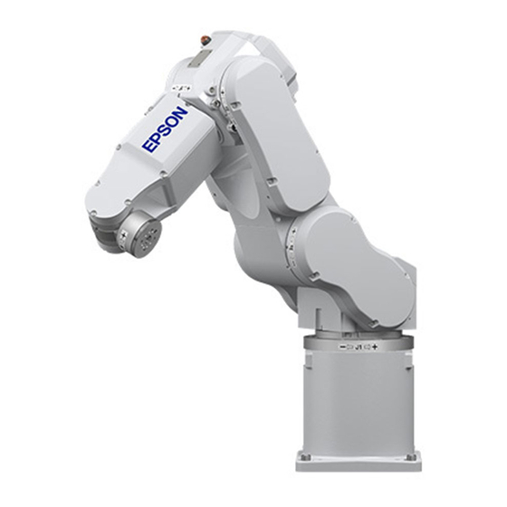
Setup & Operation 2. Specifications 2.3 Appearance Part Names and Motion Range of Each Arm Upper Arm (Arms #3 to #6) LED Lamp (This lamp lights up J3− Arm #5 while the motors are ON.) Joint #5 Joint #6 Arm #3 Arm #6 J6−... - Page 35 Setup & Operation 2. Specifications Outer Dimensions S5-A701** [Unit: mm] Air Supply Opening M5 Tap with cover plug Space for cables 90 or more 2-M4 Tap P0.7 Depth: 8mm 2×2 M4 Tap P0.7Depth 8 mm 4-M8 Tap P1.25 Depth: 16mm (Front &...
- Page 36 Setup & Operation 2. Specifications S5-A901** [Unit: mm] Air Supply Opening M5 Tap with cover plug Space 2-M4 Tap P0.7 Depth: 8mm for cables 90 or more 2×2 M4 Tap P0.7Depth 8 mm 4-M8 Tap P1.25 Depth: 16mm (Front & Back) 150.2 723.2 S5 Rev.5...
- Page 37 Setup & Operation 2. Specifications Standard Motion Range S5-A701** [Unit: mm] (° = degree) Top View +170° (Arm #1) Motion range of P point* P point* R235 Joint #1 0 pulse position R706 −170° (Arm #1) Joint #2 0 pulse position Lateral View Front View Joints #4, #6...
- Page 38 Setup & Operation 2. Specifications S5-A901** [Unit: mm] (° = degree) Top View +170° (Arm #1) Motion range of P point* P point* R267 Joint #1 0 pulse position R895 −170° (Arm #1) Joint #2 Lateral View 0 pulse position Front View Joints #4, #6 0 pulse position...
-
Page 39: Specifications
Setup & Operation 2. Specifications 2.4 Specifications 2.4.1 Specifications Table Item Specification Model Number S5-A701S S5-A701C S5-A701P S5-A901S S5-A901C S5-A901P Model Name Degree of protection IP65 IP65 Cleanliness level (ISO class) Class 4 Class 4 Weight 36 kg : 80 lb. 38 kg : 84 lb. -
Page 40: Option Table
Brake release unit 1.5.1 Moving the Arm Using the Brake Release Unit. Camera plate PS compatible plate Call your Epson Regional Sales Manager for the detail information. PS installation compatible plate Mechanical stops for Arm #1, #2, #3 * If manipulator is equipped with the mechanical stop, it conforms to the safety standard “ANSI/RIA R15.06”and “CE”, but not to “UL1740”. -
Page 41: How To Set The Model
Please contact us with the number on the MT label. The method for setting the Manipulator model depends on the software used. Refer to the chapter Robot Configuration in the EPSON RC+ User’s Guide. S5 Rev.5... -
Page 42: Environment And Installation
Setup & Operation 3. Environment and Installation 3. Environment and Installation Installation and transportation of robots and robotic equipment shall be performed by qualified personnel and should conform to all national and local codes. 3.1 Environmental Conditions A suitable environment is necessary for the robot system to function properly and safely. Be sure to install the robot system in an environment that meets the following conditions: Item Conditions... - Page 43 Setup & Operation 3. Environment and Installation For the Protection-model Manipulator, be sure to install the robot system in an environment that also meets the following conditions: Item Conditions Environment · Install indoors. · Keep away from direct sunlight. · Keep away from salinity or other contaminants. ·...
-
Page 44: Unpacking, Transportation, And Relocation
Setup & Operation 3. Environment and Installation 3.2 Unpacking, Transportation, and Relocation Using a cart or similar equipment, transport the Manipulator in the same conditions as it was delivered. Observe the following when unpacking the Manipulator. THE INSTALLATION SHALL BE MADE BY QUALIFIED INSTALLATION PERSONNEL AND SHOULD CONFORM TO ALL NATIONAL AND LOCAL CODES. -
Page 45: Using A Crane
Setup & Operation 3. Environment and Installation Use a crane for transporting the Manipulator during unpacking and relocation. When using a lifting device other than a crane or forklift for transportation, avoid applying external force to the arms and motors of the Manipulator. Check that the eyebolts are securely fastened. -
Page 46: Using A Forklift
Setup & Operation 3. Environment and Installation 3.2.2 Using a Forklift Position the Manipulator as shown in the figures below (the same posture as shipping) and secure it onto a pallet with shipping bolts and jigs. Insert the forklift claws under the pallet and transport the Manipulator together with the pallet. -
Page 47: Relocating
Setup & Operation 3. Environment and Installation Removal (1) Remove the bolts combining the shipping jigs at the point A. 6-M5×14 hexagon socket head cap bolts with plain washers and disc spring washers (2) Remove the bolts securing the shipping jigs at the point B. Then, remove the upper part of the shipping jigs. -
Page 48: Mounting Dimensions
Setup & Operation 3. Environment and Installation 3.3 Mounting Dimensions Mounting Area Be sure to have the following space available in addition to the space for mounting the Manipulator, Controller, and peripheral equipment. Space for teaching points Space for maintenance and inspections Space for cables NOTE The minimum bend radius of the power cable is 90 mm. -
Page 49: Installation
■ To ensure safety, a safeguard must be installed for the robot system. For details on the safeguard, refer to the Installation and Design Precautions in the Safety chapter of the EPSON RC+ User’s Guide or the Safety 1.3 Design Precautions in the SPEL CT User’s Guide. -
Page 50: Base Table Mounting
Setup & Operation 3. Environment and Installation 3.4.1 Base Table Mounting A base table for anchoring the Manipulator is not supplied. Please make or obtain the base table for your Manipulator. The shape and size of the base table will differ depending on the use of the robot system. -
Page 51: Floor Mounting
Setup & Operation 3. Environment and Installation Bolt (4-M10) Spring Washer Manipulator Base Manipulator Base Base Table Anchor Bolt (M10 or larger) Base Table 3.4.2 Floor Mounting The floor should have enough strength to bear the weight of the Manipulator. Construct a solid foundation with the appropriate thickness to withstand maximum torque and reaction force of the Manipulator (refer to the table in Setup &... -
Page 52: Cleanroom-Model
Setup & Operation 3. Environment and Installation 3.4.3 Cleanroom-model For Cleanroom-model Manipulator, the following procedure is necessary before installation. (1) Unpack it outside of the clean room. (2) Secure the Manipulator to delivery equipment such as a pallet with bolts so that the Manipulator does not fall. -
Page 53: Connecting The Cables
Setup & Operation 3. Environment and Installation 3.5 Connecting the Cables ■ Before performing any replacement procedure, turn OFF the Controller and related equipment, and then pull out the power plug from the power source. Performing any replacement procedure with the power ON is extremely hazardous and may result in electric shock and/or malfunction of the robot system. -
Page 54: Cable Connections
Setup & Operation 3. Environment and Installation 3.5.1 Cable Connections Cable Connections Connect the power connector and signal connector of the M/C cables to the Controller. <Example> Connection of S5 series Manipulator and Robot Controller RC180 M/C power cable M/C signal cable Cleanroom-model When the Manipulator is Cleanroom-model, be aware that it needs an exhaust system. -
Page 55: Grounding
Setup & Operation 3. Environment and Installation 3.5.2 Grounding ■ Ground resistance must be 100 Ω or less. Improper ground resistance may result in fire and/or electric shock. ■ Do not use the ground line for the Manipulator in common with other ground lines or grounding electrodes for other electric power, motor power, welding devices, etc. -
Page 56: Setting The Basic Pose For Calibration
This must be carried out as soon as the robot system is installed. Follow the procedure below to record pulses of the basic pose. For EPSON RC+, a coordinate point including the arm pose is defined as “point”. The data is called “point data”. - Page 57 (5) Display the origin data that are currently stored in the Controller and record them. (The origin data are not used in this calibration procedure. However, record the origin data in case of calibration failure.) EPSON RC+ 5.0 (RC180) Select menu-[Setup]-[Controller] to display the [Setup Controller] dialog. Select [Robot]-[Calibration] and “Hofs” values are indicated.
-
Page 58: User Wires And Pneumatic Tubes
Setup & Operation 3. Environment and Installation 3.7 User Wires and Pneumatic Tubes ■ Only authorized or certified personnel should be allowed to perform wiring. Wiring by unauthorized or uncertified personnel may result in bodily injury and/or malfunction of the robot system. CAUTION User electrical wires and pneumatic tubes are contained in the cable unit. - Page 59 Setup & Operation 3. Environment and Installation User Wires and Pneumatic Tubes User Cable Connector: JAZ-15S-3 (D sub) *JST* Prepare the connector JAZ-15P-3 (D sub) *JST*. Air Supply Opening User Cable Connector: M5 Tap View B JAZ-15P-3 (D sub) *JST* with cover plug Prepare the connector JAZ-15S-3 (D sub) *JST*.
-
Page 60: End Effectors
Setup & Operation 4. End Effectors 4. End Effectors 4.1 Attaching an End Effector Create an end effector for your Manipulator that will attach to Arm #6. Before attaching the end effector to the end of Arm #6, observe these guidelines. The wrist flange dimensions are shown in the following figure. -
Page 61: Attaching Valves
Setup & Operation 4. End Effectors 4.2 Attaching Valves There are two decks on the upper arm called “upper arm rear deck” and “upper arm center deck” as shown in the figures below to mount peripheral equipment such as valves. When the weight on the fore-end of Arm #6 is 5 kg or less, the available weight on the deck is 6 kg or less including the weight on Arm #6. - Page 62 Setup & Operation 4. End Effectors If the load or moment of inertia exceed the ratings or if the load becomes eccentric, follow the steps in the Setup & Operation 4.3.1 WEIGHT Setting and 4.3.2 INERTIA Setting, to set parameters. Setting parameters makes the operation of the Manipulator optimal, reduces vibration to shorten the operating time, and improves the capacity for larger loads.
- Page 63 Setup & Operation 4. End Effectors When calculating the critical location of the load on the Arm #5 using the allowable moment and allowable moment of inertia, the calculated value represents a distance from the Arm #5 rotation center, not the distance from the flange. Therefore, to get a value of the critical location of the load on Arm #5, subtract 80 (mm) from the calculated distance from the Arm #5 rotation center as shown the example below.
-
Page 64: Weight Setting
7 kg)” in the later part of this section for details. Setting method of Weight parameters From EPSON RC+-[Tools]-[Robot Manager], enter into the [Weight:] text box on the [Weight] panel. You may also execute the Weight command from [Command Window]. - Page 65 Setup & Operation 4. End Effectors Load on the Manipulators The Manipulator can load valves or any other devices onto the following two points. A point on the fore-end of the Arm #6 Upper arm deck Upper Arm Deck Load on the Fore-end of Arm #6 View A When you attach the equipment to the deck on the upper arm, convert its weight into...
- Page 66 Setup & Operation 4. End Effectors <Example> The fore-end of Arm #6 is 385 mm (L) away from the Joint #3. Load on the fore-end of Arm #6 is 1 kg (M Load on the upper arm deck is 1.5 kg (m The deck is 60 mm (L ) away from Joint #3.
- Page 67 Setup & Operation 4. End Effectors Restrictions on payload exceeding 5 kg (more than 5 kg and less than or equal to 7 kg) Although the maximum payload of the S5 series Manipulator is 5 kg, you can increase the payload up to 7 kg when you restrict the arm pose range of Arm #5 as shown below.
-
Page 68: Inertia Setting
The moment of inertia of load (weight of the end effector and work piece) on Arm #6 can be set by the “moment of inertia (INERTIA)” parameter of the INERTIA command. From EPSON RC+-[Tools]-[Robot Manager], enter into the [Load inertia:] text box on the [Inertia] panel. - Page 69 Enter the larger value of “a” or “b” in the figure above to the [Eccentricity] text box. The method for setting the parameter varies with the software used. From EPSON RC+-[Tools]-[Robot Manager], enter into the [Eccentricity:] text box on the [Inertia] panel.
- Page 70 Setup & Operation 4. End Effectors Calculating the Moment of Inertia Refer to the following examples of formulas to calculate the moment of inertia of load (end effector with work piece). The moment of inertia of the entire load is calculated by the sum of each part (a), (b), and (c).
- Page 71 Setup & Operation 4. End Effectors (a) Moment of inertia of a rectangular parallelepiped Rotation Center Rectangular Parallelepiped’s Center of Gravity Weight = m + m × L (b) Moment of inertia of a cylinder Cylinder’s Center of Gravity Rotation Center + m ×...
-
Page 72: Precautions For Auto Acceleration/Deceleration
Setup & Operation 4. End Effectors 4.4 Precautions for Auto Acceleration/Deceleration The speed and acceleration / deceleration of the Manipulator motion are automatically optimized according to the values of WEIGHT and INERTIA and the Manipulator’s postures. WEIGHT Setting The speed and acceleration / deceleration of the Manipulator are controlled according to the load weight set by the WEIGHT command. -
Page 73: Motion Range
Setup & Operation 5. Motion Range 5. Motion Range ■ When setting up the motion range for safety, both the pulse range and mechanical stops must always be set at the same time. Failure to set both of them together may cause serious safety problems. WARNING The motion range is preset at the factory as explained in the section “Standard Motion Range”... -
Page 74: Motion Range Setting By Pulse Range (For All Arms)
Manipulator does not move. The pulse range can be set from EPSON RC+-[Tools]-[Robot manager]-[Range] panel. You may also execute the Range command from the [Command Window]. -
Page 75: Max. Pulse Range Of Arm #1
Setup & Operation 5. Motion Range 5.1.1 Max. Pulse Range of Arm #1 The 0 pulse position for Arm #1 is shown in the figure below. Counterclockwise pulse values are positive (+) and clockwise pulse values are negative (-). S5-A701** Top View +170°... -
Page 76: Max. Pulse Range Of Arm #2
Setup & Operation 5. Motion Range 5.1.2 Max. Pulse Range of Arm #2 The 0 pulse position for Arm #2 is shown in the figure below. Counterclockwise pulse values are positive (+) and clockwise pulse values are negative (-). S5-A701** Lateral View Arm #2 0 pulse position +65 deg. -
Page 77: Max. Pulse Range Of Arm #3
Setup & Operation 5. Motion Range 5.1.3 Max. Pulse Range of Arm #3 The 0 pulse position for Arm #3 is shown in the figure below. Counterclockwise pulse values are positive (+) and clockwise pulse values are negative (-). S5-A701** Lateral View +190 deg. -
Page 78: Max. Pulse Range Of Arm #4
Setup & Operation 5. Motion Range 5.1.4 Max. Pulse Range of Arm #4 The 0 pulse position for Arm #4 is shown in the figure below. Clockwise pulse values are positive (+) and counterclockwise pulse values are negative (-). S5-A701** Front View Arm #4 0 pulse position −190 deg. -
Page 79: Max. Pulse Range Of Arm #5
Setup & Operation 5. Motion Range 5.1.5 Max. Pulse Range of Arm #5 The 0 pulse position for Arm #5 is shown in the figure below. Counterclockwise pulse values are positive (+) and clockwise pulse values are negative (-). S5-A701** Lateral View +3932160 pulse +135 deg. -
Page 80: Max. Pulse Range Of Arm #6
Setup & Operation 5. Motion Range 5.1.6 Max. Pulse Range of Arm #6 The 0 pulse position for Arm #6 is shown in the figure below. Clockwise pulse values are positive (+) and counterclockwise pulse values are negative (-). S5-A701** Front View Arm #6 0 pulse position −360 deg. -
Page 81: Restriction Of Manipulator Operation By Joint Angle Combination
Setup & Operation 5. Motion Range 5.2 Restriction of Manipulator Operation by Joint Angle Combination To prevent the arms of the Manipulator from interfering each other, the Manipulator operation is restricted in the specified motion range according to the joint angle combination of the Arm #2, #3, and #4. - Page 82 Setup & Operation 5. Motion Range Combination of Joint #3 and #4 S5-A701** Joint #3 Angle (degree) S5-A901** Joint #3 Angle (degree) The restriction to Manipulator operation is enabled: During CP motion command execution You attempt to execute the motion command for moving the Manipulator to a target point (or pose) in the specified motion range.
-
Page 83: Coordinate System
Manipulator or peripheral equipment. The method for changing the XYLim setting varies with the software used. Set the XYLim setting from EPSON RC+-[Tools]-[Robot manager]-[XYZ Limits] panel. You may also execute the XYLim command from the [Command Window]. - Page 84 Setup & Operation 5. Motion Range S5 Rev.5...
-
Page 85: Maintenance
Maintenance This volume contains maintenance procedures with safety precautions for Manipulators. - Page 86 S5 Rev.5...
-
Page 87: Safety Maintenance
Maintenance 1. Safety Maintenance 1. Safety Maintenance Please read this manual and other relevant manuals carefully to understand safe maintenance procedures before performing any maintenance. Only authorized personnel who have taken the safety training should be allowed to maintain the robot system. The safety training is the program for the industrial robot operator that follows the laws and regulations of each nation. - Page 88 Maintenance 1. Safety Maintenance ■ Carefully use alcohol, liquid gasket, and adhesive following respective instructions and also instructions below. Careless use of alcohol, liquid gasket, or adhesive may cause a fire and/or safety problems. - Never put alcohol, liquid gasket, or adhesive close to fire. - Use alcohol, liquid gasket, or adhesive while ventilating the room.
-
Page 89: Periodic Inspection
Maintenance 2. Periodic Inspection 2. Periodic Inspection Performing the inspection steps properly is essential to preventing trouble and maintaining safety. This section describes the schedule for maintenance inspections and the procedures. Be sure to perform the maintenance inspections in accordance with the schedule. 2.1 Schedule for Maintenance Inspections Inspection tasks are divided into five stages: daily, 4 months, 24 months, 48 months, and 96 months. -
Page 90: Inspection Tasks
Maintenance 2. Periodic Inspection 2.2 Inspection Tasks Related Inspection Tasks Inspection Method Inspection and Maintenance Details Check for tram mark misalignment or damage Tram mark Daily Visual at the home position. Clean the area of motion range for each joint if Motion range Daily Visual... - Page 91 Maintenance 2. Periodic Inspection When the Manipulator is a Protection-model, be check of the followings. Inspection Tasks Inspection Method Inspection and Maintenance Related Details Arm #1 - #4 Keep the oil seals clean removing any Daily Visual Oil Seals dust such as metal powders. Drain plug Screw-driver, Remove the condensation if it...
-
Page 92: Grease Replenishment
Maintenance 2. Periodic Inspection 2.3 Grease Replenishment The reduction gear units need greasing at intervals of 6000 hours of operation time. Use only the grease specified. ■ Move out of the safeguarded area before operating the Manipulator for run-in during grease replenishment. Operating the Manipulator while someone is inside of the safeguarded area is extremely hazardous and may cause serious WARNING... - Page 93 Maintenance 2. Periodic Inspection Grease Gun Lubrication Nozzle Shape Use a commercially available grease gun. We recommend the use of a grease gun with a nozzle shaped like that shown in the figure below and an outer diameter (øD) 13 mm or less. Straight Chuck Hose...
-
Page 94: Joint #1 Reduction Gear Unit
Maintenance 2. Periodic Inspection 2.3.1 Joint #1 Reduction Gear Unit Reduction Air Vent Gear Unit (Hexagon Socket Head Grease Inlet Cap Plug PT1/8) (Hexagon Socket Head Cap Bolt : M6) Name Quantity Note Maintenance Grease for reduction gear 25 g SK-1A R13ZA00330100 Parts... -
Page 95: Joint #1 Gear
Maintenance 2. Periodic Inspection 2.3.2 Joint #1 Gear Air Vent Gear of (Hexagon Socket Grease Inlet Joint #1 Motor Head Cap Plug (Hexagon Socket : PT1/8) Head Cap Plug : PT1/8) Name Quantity Note Maintenance Grease for reduction gear 25 g SK-1A R13ZA00330100 Parts... -
Page 96: Joint #2 Reduction Gear Unit
Maintenance 2. Periodic Inspection 2.3.3 Joint #2 Reduction Gear Unit Joint #2 Motor Air Vent (Plug M5) Joint #2 Reduction Grease Inlet Gear Unit (Hexagon Socket Head Cap Bolt: M6) Name Quantity Note Maintenance Grease for reduction gear 30 g SK-1A R13ZA00330100 Parts... -
Page 97: Joint #3 Reduction Gear Unit
Maintenance 2. Periodic Inspection 2.3.4 Joint #3 Reduction Gear Unit Air Vent (Plug M5) Cover Joint #3 Reduction Gear Unit Grease Inlet (Hexagon Socket Joint #3 Motor Head Cap Bolt : M6) Name Quantity Note Maintenance Grease for reduction gear 20 g SK-1A R13ZA00330100... -
Page 98: Joint #4 Reduction Gear Unit
Maintenance 2. Periodic Inspection 2.3.5 Joint #4 Reduction Gear Unit Grease Inlet (Plug M5) Air Vent (Plug M5) Name Quantity Note Maintenance Grease for reduction gear SK-1A R13ZA00330100 Parts Liquid gasket Proper quantity 1206C R13B031201 (1) Remove the bolts and then remove the Arm #4 Cover. For details, refer to Maintenance: 3.4 Arm #4 Cover. -
Page 99: Joint #5 Reduction Gear Unit
Maintenance 2. Periodic Inspection 2.3.6 Joint #5 Reduction Gear Unit Air Vent (Plug M5) Grease Inlet (Plug M5) Name Quantity Note Maintenance Grease for reduction gear SK-1A R13ZA00330100 Parts Liquid gasket Proper quantity 1206C R13B031201 (1) Remove the plug from the air vent. Plug: LP-M5 NOTE Be sure to remove the plug from the air vent. -
Page 100: Joint #6 Reduction Gear Unit
Maintenance 2. Periodic Inspection 2.3.7 Joint #6 Reduction Gear Unit Air Vent: Gear part (Plug M5) Air Vent: Reduction Gear Unit (Plug M5) Grease Inlet: Gear part (Plug M5) Grease Inlet: Reduction Gear Unit (Plug M5) Name Quantity Note Maintenance Grease for reduction gear SK-1A R13ZA00330100... -
Page 101: Tightening Hexagon Socket Head Cap Bolts
Maintenance 2. Periodic Inspection 2.4 Tightening Hexagon Socket Head Cap Bolts Hexagon socket head cap bolts are used where mechanical strength is required. These bolts are fastened with the tightening torques shown in the following table. When it is necessary to refasten these bolts during procedures in this manual (except special cases as noted), use a torque wrench so that the bolts are fastened with the appropriate tightening torques as shown below. -
Page 102: Removing Condensation (Only Protection-Model)
Maintenance 2. Periodic Inspection 2.5 Removing Condensation (Only protection-model) For protection-model manipulators, condensation water should be drained. Name Quantity Note Proper quantity Liquid gasket (1206C) R13B031201 Maintenance R13B031275 Parts Gasket For replacement (1) Remove the bolt. Detach the drain cover and the gasket of the No.1 drain vent. -
Page 103: Covers
Maintenance 3. Covers 3. Covers The common procedure for removing the covers for maintenance are described in this chapter. ■ Before performing any replacement procedure, turn OFF the Controller and related equipment, and then pull out the power plug from the power source. Performing any replacement procedure with the power ON is extremely hazardous and may result in electric shock and/or malfunction of the robot system. -
Page 104: Arm #1 Cover
Maintenance 3. Covers 3.1 Arm #1 Cover Remove the bolts and then remove the Arm #1 Cover. Tool : Hexagonal wrench (width across flats: 3 mm) Button bolt : 6-M4×10 Tightening torque : 1.4 N·m (0.14 kg·m) For cleanroom-model: A gasket (R13B031270) is attached. Removal Remove the gasket with the cover. -
Page 105: Arm #2 Cover
Maintenance 3. Covers 3.2 Arm #2 Cover Remove the bolts and then remove the Arm #2 Cover. Tool : Hexagonal wrench (width across flats: 4 mm) Button bolt : 20-M5×10 (with washer) Tightening torque : 2.8 N·m (0.29 kg·m) NOTE There is one cover on each side. -
Page 106: Arm #3 Cover
Maintenance 3. Covers 3.3 Arm #3 Cover Remove the bolts and then remove the Arm #3 Cover. Tool : Hexagonal wrench (width across flats: 3 mm) Button bolt : 4-M4×10 (with washer) Tightening torque : 1.4 N·m (0.14 kg·m) For cleanroom-model: A gasket (R13B031273) is attached. -
Page 107: Arm #4 Cover
Maintenance 3. Covers 3.4 Arm #4 Cover Remove the bolts and then remove the Arm #4 Cover. Tool : Hexagonal wrench (width across flats: 3 mm) Button bolt : 18-M4×10 (with washer) Tightening torque : 1.4 N·m (0.14 kg·m) NOTE There is one cover on each side. -
Page 108: Connector Plate
Maintenance 3. Covers 3.5 Connector Plate Remove the bolts, and then remove the Connector Plate. Tool: Hexagonal wrench (width across flats: 3 mm) Button head bolts: 8-M4×10 (with a washer) Tightening torque: 1.4 N·m (0.14 kg·m) For Cleanroom model There is a gasket between the cover and the (R13B031269) body. -
Page 109: Connector Sub Plate
Maintenance 3. Covers 3.6 Connector Sub Plate Remove the bolts, and then remove the Connector Sub Plate. Tool: Hexagonal wrench (width across flats: 3 mm) Hexagon socket head cap bolts: 4-M4×10 Tightening torque 1.4 N·m (0.14 kg·m) For Protection model Remove the bolts, and then remove the Connector Sub Plate. -
Page 110: Joint #1
Maintenance 4. Joint #1 (Replacing the Motor) 4. Joint #1 4.1 Replacing the Joint #1 Motor ■ Before performing any replacement procedure, turn OFF the Controller and related equipment, and then pull out the power plug from the power source. Performing any replacement procedure with the power ON is extremely hazardous and may result in electric shock and/or malfunction of the robot system. - Page 111 Maintenance 4. Joint #1 (Replacing the Motor) ■ Wear protective gear including a mask, protective goggles, and oil-resistant gloves during grease up. If grease gets into your eyes, mouth, or on your skin, follow the instructions below. If grease gets into your eyes : Flush them thoroughly with clean water, and then see a doctor immediately.
- Page 112 Maintenance 4. Joint #1 (Replacing the Motor) Joint #1 Motor (1) Remove the manipulator installation bolts and put the manipulator on its side. Removal NOTE Before removing the installation bolts, position the manipulator to make sure you can put the manipulator back in the installation position. If the manipulator installation position changes after the motor replacement, you need to adjust the points already taught.
- Page 113 Maintenance 4. Joint #1 (Replacing the Motor) (8) Remove the Joint #1 motor plate from the Joint #1 motor. (9) Remove caked-on liquid gasket residue with a scraper or similar tool. S5 Rev.5...
- Page 114 Maintenance 4. Joint #1 (Replacing the Motor) NOTE Double-check the bolts to make sure that you have not forgotten to tighten any of them. Joint # Motor (1) Mount the Joint #1 motor plate on the Joint #1 Installation motor.
- Page 115 Maintenance 4. Joint #1 (Replacing the Motor) (7) Remove the backup battery. (8) Mount the Bottom Cover. Button bolt : 6-M4×10 Tightening torque : 1.4 N·m (0.14 kgf·m) (9) Put the manipulator in the installation position. S5 Rev.5...
-
Page 116: Replacing The Joint #1 Reduction Gear Unit
Maintenance 4. Joint #1 (Replacing the Reduction Gear Unit) 4.2 Replacing the Joint #1 Reduction Gear Unit ■ Before performing any replacement procedure, turn OFF the Controller and related equipment, and then pull out the power plug from the power source. Performing any replacement procedure with the power ON is extremely hazardous and may result in electric shock and/or malfunction of the robot system. -
Page 117: Greasing The Reduction Gear Unit
Maintenance 4. Joint #1 (Replacing the Reduction Gear Unit) NOTE - After parts have been replaced (motors, reduction gear units, timing belts, etc.), the Manipulator cannot perform positioning properly because a mismatch exists between the origin stored in each motor encoder and its corresponding origin stored in the Controller. After replacing the parts, it is necessary to match these origins. -
Page 118: Replacing The Reduction Gear Unit
Maintenance 4. Joint #1 (Replacing the Reduction Gear Unit) 4.2.2 Replacing the Reduction Gear Unit ■ Use at least three people when removing the upper structure (Arms #1 to #6). One should support the upper arm and the others should hold Arm #1 up. The upper structure is so heavy that attempting this task requires a large force. - Page 119 Maintenance 4. Joint #1 (Replacing the Reduction Gear Unit) (6) Remove the GT-SA bolts and then remove the bearing holder. GT-SA bolt: 4-M4×10 (7) Remove the Joint #1 output gear. Hexagon socket head cap bolt : 6-M3×30 (with disc spring) (8) Detach the Base and Arm #1.
- Page 120 Maintenance 4. Joint #1 (Replacing the Reduction Gear Unit) (10) Remove the circular spline and flexspline from the Arm #1. Hexagon socket head cap bolt : 12-M5×40 (with disc spring) (11) Remove the bearing from the waveform generator using a hand press or similar tool. (12) Remove the bearing from the Joint #1 output gear.
- Page 121 Maintenance 4. Joint #1 (Replacing the Reduction Gear Unit) NOTE Double-check the bolts to make sure that you have not forgotten to tighten any of them. Joint #1 (1) Apply liquid gasket to contact surfaces of the Reduction Gear circular spline, flexspline, and Arm #1.
- Page 122 Maintenance 4. Joint #1 (Replacing the Reduction Gear Unit) (5) Insert the waveform generator into the circular spline and flexspline. (6) Apply liquid gasket to contact surfaces of the circular spline and flexspine of the Base. (7) Mount the circular spline and flexspline to the Base. Press the bearing into the Joint #1 output gear.
- Page 123 Maintenance 4. Joint #1 (Replacing the Reduction Gear Unit) (10) Mount the bearing holder. GT-SA bolt : 4-M4×10 Tightening torque : 2.8 N·m (0.29 kgf·m) (11) Apply grease for reduction gear around the Joint #1 output gear. Grease for reduction gear: SK-1A (12) Apply liquid gasket on the flange surface where it joins with the Base.
-
Page 124: Joint #2
Maintenance 5. Joint #2 (Replacing the Motor) 5. Joint #2 5.1 Replacing the Joint #2 Motor ■ Before performing any replacement procedure, turn OFF the Controller and related equipment, and then pull out the power plug from the power source. Performing any replacement procedure with the power ON is extremely hazardous and may result in electric shock and/or malfunction of the robot system. - Page 125 Maintenance 5. Joint #2 (Replacing the Motor) ■ Wear protective gear including a mask, protective goggles, and oil-resistant gloves during grease up. If grease gets into your eyes, mouth, or on your skin, follow the instructions below. If grease gets into your eyes : Flush them thoroughly with clean water, and then see a doctor immediately.
- Page 126 Maintenance 5. Joint #2 (Replacing the Motor) Name Quantity Note AC servo motor 400W R13B000626 Maintenance Grease for reduction gear Proper quantity SK-1A R13ZA00330100 Parts Liquid gasket Proper quantity 1206C R13B031201 Adhesive Proper quantity Loctite 242 R13B031701 Material Wire tie NOTE ...
- Page 127 Maintenance 5. Joint #2 (Replacing the Motor) NOTE Double-check the bolts to make sure that you have not forgotten to tighten any of them. Joint #2 Motor (1) Mount the Joint #2 input pulley to the Joint #2 motor. Installation Hexagon socket head cap bolt : 1-M5×16 (with disc spring 2H-5) Apply adhesive.
-
Page 128: Replacing The Joint #2 Reduction Gear Unit
Maintenance 5. Joint #2 (Replacing the Reduction Gear Unit) 5.2 Replacing the Joint #2 Reduction Gear Unit ■ Before performing any replacement procedure, turn OFF the Controller and related equipment, and then pull out the power plug from the power source. Performing any replacement procedure with the power ON is extremely hazardous and may result in electric shock and/or malfunction of the robot system. - Page 129 Maintenance 5. Joint #2 (Replacing the Reduction Gear Unit) NOTE - After parts have been replaced (motors, reduction gear units, timing belts, etc.), the Manipulator cannot perform positioning properly because a mismatch exists between the origin stored in each motor encoder and its corresponding origin stored in the Controller. After replacing the parts, it is necessary to match these origins.
-
Page 130: Greasing The Reduction Gear Unit
Maintenance 5. Joint #2 (Replacing the Reduction Gear Unit) 5.2.1 Greasing the Reduction Gear Unit ■ Wear protective gear including a mask, protective goggles, and oil-resistant gloves during grease up. If grease gets into your eyes, mouth, or on your skin, follow the instructions below. -
Page 131: Replacing The Reduction Gear Unit
Maintenance 5. Joint #2 (Replacing the Reduction Gear Unit) 5.2.2 Replacing the Reduction Gear Unit ■ Always use at least two people when removing the motor unit. Remove the motor unit while one person is supporting the upper structure (Arms #2 to #6). The upper structure folds inward at Joint #2 as soon as the motor unit is removed and the brake is released. - Page 132 Maintenance 5. Joint #2 (Replacing the Reduction Gear Unit) (5) From the waveform generator, remove the Joint #2 output pulley. Hexagon socket head cap bolt: 1-M5×20 (with disc spring 2H-5) (6) From the waveform generator, remove the housing. (7) From the housing, remove the bearing. (8) From the waveform generator, remove the bearing.
- Page 133 Maintenance 5. Joint #2 (Replacing the Reduction Gear Unit) (10) Remove the housing from the Arm #2. GT-SA bolt: 6-M4×10 NOTE When the housing is removed, the Arm #1 and Arm #2 are detached. Therefore, hold the Arm #2 while removing the housing. (11) Remove the bearing and oil seal from the Arm #1.
- Page 134 Maintenance 5. Joint #2 (Replacing the Reduction Gear Unit) NOTE Double-check the bolts to make sure that you have not forgotten to tighten any of them. Joint #2 (1) Mount the flexspline to the Arm #1. Reduction Gear Hexagon socket head cap bolt Unit : 30-M4×16 (with disc spring 2H-4) Installation...
- Page 135 Maintenance 5. Joint #2 (Replacing the Reduction Gear Unit) (4) Press the oil seal into the Arm #1. NOTE - Before mounting the oil seal, wipe off any liquid gasket on the Arm #1. - The height of the oil seal surface and Arm #1 surface should be the same. (5) Apply grease for the reduction gear unit on the teeth of the flexspline.
- Page 136 Maintenance 5. Joint #2 (Replacing the Reduction Gear Unit) (9) Apply liquid gasket to the inside of the housing. (10) Press the waveform generator into the housing. (11) Mount the Joint #2 output pulley to the waveform generator. Hexagon socket head cap bolt : 1-M5×20 (with disc spring 2H-5) Tightening torque : 10 N·m (1.02 kgf·m)
- Page 137 Maintenance 5. Joint #2 (Replacing the Reduction Gear Unit) (15) Insert the housing into the Arm #2 and bearing. GT-SA bolt : 6-M4×10 Tightening torque : 2.8 N·m (0.29 kgf·m) NOTE If the housing is not easily inserted, tap the housing using a plastic hammer or similar ...
-
Page 138: Replacing The Joint #2 Timing Belt
Maintenance 5. Joint #2 (Replacing the Timing Belt) 5.3 Replacing the Joint #2 Timing Belt ■ Before performing any replacement procedure, turn OFF the Controller and related equipment, and then pull out the power plug from the power source. Performing any replacement procedure with the power ON is extremely hazardous and may result in electric shock and/or malfunction of the robot system. - Page 139 Maintenance 5. Joint #2 (Replacing the Reduction Gear Unit) Joint #2 (1) Remove the Arm #2 Cover. Timing belt For details, refer to Maintenance: 3.2 Arm #2 Cover. Removal (2) Remove the bolts of the motor plate and then remove the timing belt from the pulley.
-
Page 140: Joint #3
Maintenance 6. Joint #3 (Replacing the Motor) 6. Joint #3 6.1 Replacing the Joint #3 Motor ■ Before performing any replacement procedure, turn OFF the Controller and related equipment, and then pull out the power plug from the power source. Performing any replacement procedure with the power ON is extremely hazardous and may result in electric shock and/or malfunction of the robot system. - Page 141 Maintenance 6. Joint #3 (Replacing the Motor) ■ Wear protective gear including a mask, protective goggles, and oil-resistant gloves during grease up. If grease gets into your eyes, mouth, or on your skin, follow the instructions below. If grease gets into your eyes : Flush them thoroughly with clean water, and then see a doctor immediately.
- Page 142 Maintenance 6. Joint #3 (Replacing the Motor) Name Quantity Note AC servo motor 200W R13B000627 Maintenance Grease for reduction gear Proper quantity SK-1A R13ZA00330100 Parts Liquid gasket Proper quantity 1206C R13B031201 Adhesive Proper quantity Loctite 242 R13B031701 Material Wire tie NOTE We recommend folding the upper structure (Arms #3 to #6) to the stop side before the ...
- Page 143 Maintenance 6. Joint #3 (Replacing the Motor) NOTE Double-check the bolts to make sure that you have not forgotten to tighten any of them. Joint #3 Motor (1) Mount the Joint #3 input pulley to the Joint #3 motor. Installation Hexagon socket head cap bolt : 1-M4×18 (with disc spring 2H-4, M4 washer) Apply adhesive.
-
Page 144: Replacing The Joint #3 Reduction Gear Unit
Maintenance 6. Joint #3 (Replacing the Reduction Gear Unit) 6.2 Replacing the Joint #3 Reduction Gear Unit ■ Before performing any replacement procedure, turn OFF the Controller and related equipment, and then pull out the power plug from the power source. Performing any replacement procedure with the power ON is extremely hazardous and may result in electric shock and/or malfunction of the robot system. -
Page 145: Greasing The Reduction Gear Unit
Maintenance 6. Joint #3 (Replacing the Reduction Gear Unit) NOTE - After parts have been replaced (motors, reduction gear units, timing belts, etc.), the Manipulator cannot perform positioning properly because a mismatch exists between the origin stored in each motor encoder and its corresponding origin stored in the Controller. After replacing the parts, it is necessary to match these origins. - Page 146 Maintenance 6. Joint #3 (Replacing the Reduction Gear Unit) When greasing the reduction gear unit, use only the grease specified for the reduction gear unit. While greasing the reduction gear unit, be careful not to allow any foreign substances in the grease.
-
Page 147: Replacing The Reduction Gear Unit
Maintenance 6. Joint #3 (Replacing the Reduction Gear Unit) 6.2.2 Replacing the Reduction Gear Unit ■ Always use at least two people when removing the motor unit. Remove the motor unit while one person is supporting the upper structure (Arms #3 to #6). The upper structure folds inward at Joint #3 as soon as the motor unit is removed and the brake is released. - Page 148 Maintenance 6. Joint #3 (Replacing the Reduction Gear Unit) (4) From the waveform generator, remove the housing. (5) From the housing, remove the bearing. (6) From the waveform generator, remove the bearing. (7) Remove the circular spline from the Arm #2. Hexagon socket head cap bolt: 6-M4×12 (8) Remove the housing from the Arm #2.
- Page 149 Maintenance 6. Joint #3 (Replacing the Reduction Gear Unit) (9) Remove the bearing and oil seal from the Arm #3. (10) Remove the flexspline from the Arm #3. Hexagon socket head cap bolt: 32-M3×10 (with disc spring 2H-3) (11) Remove caked-on liquid gasket residue with a scraper or similar tool. (12) Repair scratches incurred during tap use with a sharpening stone or similar tool.
- Page 150 Maintenance 6. Joint #3 (Replacing the Reduction Gear Unit) NOTE Double-check the bolts to make sure that you have not forgotten to tighten any of them. Joint #3 (1) Mount the flexspline to the Arm #3. Reduction Gear Hexagon socket head cap bolt: Unit 32-M3×10 (with disc spring 2H-3) Installation...
- Page 151 Maintenance 6. Joint #3 (Replacing the Reduction Gear Unit) (6) Press the bearing into the waveform generator. (7) Apply liquid gasket to inside of the bearing. (8) Press the bearing into the waveform generator. (9) Apply liquid gasket to inside of the housing. (10) Press the waveform generator into the housing.
- Page 152 Maintenance 6. Joint #3 (Replacing the Reduction Gear Unit) (12) Apply grease on teeth of the circular spline. Grease for reduction gear unit: SK-1A (13) Insert the bearing into the opposite side of the Arm #3’s reduction gear unit mounting surface.
- Page 153 Maintenance 6. Joint #3 (Replacing the Reduction Gear Unit) (19) Mount the housing and circular spline. (20) Mount the Joint #3 motor unit to the manipulator. For details, refer to Maintenance: 6.1 Replacing the Joint #3 Motor. (21) Mount the cables to inside of the manipulator. For details, refer to Maintenance: 9.1 Replacing the Cable Unit.
-
Page 154: Replacing The Joint #3 Timing Belt
Maintenance 6. Joint #3 (Replacing the Timing Belt) 6.3 Replacing the Joint #3 Timing Belt ■ Before performing any replacement procedure, turn OFF the Controller and related equipment, and then pull out the power plug from the power source. Performing any replacement procedure with the power ON is extremely hazardous and may result in electric shock and/or malfunction of the robot system. - Page 155 Maintenance 6. Joint #3 (Replacing the Timing Belt) Joint #3 (1) Remove the Arm #2 Cover. Timing belt For details, refer to Maintenance: 3.2 Arm #2 Cover. Removal (2) Remove the bolts of the motor plate and then remove the timing belt from the pulley.
-
Page 156: Joint #4
Maintenance 7. Joint #4 (Replacing the Motor) 7. Joint #4 7.1 Replacing the Joint #4 Motor ■ Before performing any replacement procedure, turn OFF the Controller and related equipment, and then pull out the power plug from the power source. Performing any replacement procedure with the power ON is extremely hazardous and may result in electric shock and/or malfunction of the robot system. - Page 157 Maintenance 7. Joint #4 (Replacing the Motor) NOTE After parts have been replaced (motors, reduction gear units, timing belts, etc.), the Manipulator cannot perform positioning properly because a mismatch exists between the origin stored in each motor encoder and its corresponding origin stored in the Controller. After replacing the parts, it is necessary to match these origins.
- Page 158 Maintenance 7. Joint #4 (Replacing the Motor) NOTE Double-check the bolts to make sure that you have not forgotten to tighten any of them. Joint #4 Motor (1) Mount the pulley to the Joint #4 motor. Installation Hexagon socket head cap bolt: M3×12 (with disc spring 2H-3) Apply adhesive.
-
Page 159: Replacing The Joint #4 Reduction Gear Unit
Maintenance 7. Joint #4 (Replacing the Reduction Gear Unit) 7.2 Replacing the Joint #4 Reduction Gear Unit ■ Before performing any replacement procedure, turn OFF the Controller and related equipment, and then pull out the power plug from the power source. Performing any replacement procedure with the power ON is extremely hazardous and may result in electric shock and/or malfunction of the robot system. -
Page 160: Greasing The Reduction Gear Unit
Maintenance 7. Joint #4 (Replacing the Reduction Gear Unit) NOTE - After parts have been replaced (motors, reduction gear units, timing belts, etc.), the Manipulator cannot perform positioning properly because a mismatch exists between the origin stored in each motor encoder and its corresponding origin stored in the Controller. After replacing the parts, it is necessary to match these origins. -
Page 161: Replacing The Reduction Gear Unit
Maintenance 7. Joint #4 (Replacing the Reduction Gear Unit) 7.2.2 Replacing the Reduction Gear Unit NOTE When replacing the reduction gear unit, the bearings should be replaced together. Name Quantity Note Reduction gear unit R13B010036 Grease for reduction gear Proper quantity SK-1A R13ZA00330100... - Page 162 Maintenance 7. Joint #4 (Replacing the Reduction Gear Unit) (5) Remove the bolts and then remove the wrist from the Arm #3. Hexagon socket head cap bolt : 4-M6×16 (with disc spring 2H-6) (6) Remove the bolts and then remove the pulley and washer from waveform generator. GT-SA bolt : 3-M3×10 (7) Remove the bolts and then remove the Joint #4 reduction gear unit using the removal...
- Page 163 Maintenance 7. Joint #4 (Replacing the Reduction Gear Unit) NOTE Double-check the bolts to make sure that you have not forgotten to tighten any of them. Joint #4 (1) Apply liquid gasket to contact surfaces of the circular spline, flexspline, and spacer. Reduction Gear Liquid gasket (1206C) Unit...
- Page 164 Maintenance 7. Joint #4 (Replacing the Reduction Gear Unit) (6) Apply liquid gasket to outer periphery of the bearing. Bearing : 6806ZZ Liquid gasket : 1206C (7) Insert the circular spline and flexspline into the waveform generator. (8) Apply liquid gasket to outer periphery of the bearing. Bearing : 6808ZZ*NS7* Liquid gasket : 1206C...
- Page 165 Maintenance 7. Joint #4 (Replacing the Reduction Gear Unit) (13) Apply liquid gasket to contact surfaces of the spacer and Wrist Unit. Liquid gasket: 1206C (14) Mount the spacer to the Wrist Unit. Hexagon socket head cap bolt : 4-M6×16 (with disc spring 2H-6) Tightening torque: 10 N·m (1.02 kgf·m) (15) Apply liquid gasket to the contact surfaces of the spacer and Arm #3.
- Page 166 Maintenance 7. Joint #4 (Replacing the Reduction Gear Unit) (18) Confirm that the specified tension is applied to the belt. Belt tension: 19.6 ~ 26.5 N (2.0 ~ 2.7 kgf) (19) Mount the pipe to the Arm #3. GT-SA bolt : 2-M3×12 Tightening torque : 1.4 N·m (0.14 kgf·m) NOTE...
-
Page 167: Replacing The Joint #4 Timing Belt
Maintenance 7. Joint #4 (Replacing the Timing Belt) 7.3 Replacing the Joint #4 Timing Belt ■ Before performing any replacement procedure, turn OFF the Controller and related equipment, and then pull out the power plug from the power source. Performing any replacement procedure with the power ON is extremely hazardous and may result in electric shock and/or malfunction of the robot system. - Page 168 Maintenance 7. Joint #4 (Replacing the Timing Belt) Joint #4 (1) Remove the Arm #3 Cover. Timing belt For details, refer to Maintenance: 3.3 Arm #3 Cover. Removal (2) Remove the timing belt. Follow the removal steps (1) to (4) in Maintenance: 7.2.2 Replacing the Joint #4 Timing belt Reduction Gear Unit.
-
Page 169: Joint #5 & Joint #6
Maintenance 8. Joint #5 & Joint #6 (Replacing the Motor) 8. Joint #5 & Joint #6 8.1 Replacing the Joint #5 & Joint #6 Motor ■ Before performing any replacement procedure, turn OFF the Controller and related equipment, and then pull out the power plug from the power source. Performing any replacement procedure with the power ON is extremely hazardous and may result in electric shock and/or malfunction of the robot system. - Page 170 Maintenance 8. Joint #5 & Joint #6 (Replacing the Motor) Joint #5 Motor Joint #6 Motor Name Quantity Note Maintenance AC servo motor R13B000629 Common for Joint #5, Joint #6 Parts Adhesive Proper quantity Loctite 242 R13B031701 Material Wire tie ■...
- Page 171 Maintenance 8. Joint #5 & Joint #6 (Replacing the Motor) (6) Remove the two types of bolts and then remove the bracket. Hexagon socket head cap bolt : 2-M2.6×5 GT-SA bolt : 2-M3×12 (7) Remove the electromagnetic brake. (8) Remove the bolts and then remove the motor plate. GT-SA bolt: 2-M3×12 (with M3 washer) (9) Remove the set screws and then remove the rotor hub.
- Page 172 Maintenance 8. Joint #5 & Joint #6 (Replacing the Motor) NOTE Double-check the bolts to make sure that you have not forgotten to tighten any of them. Joint #5 & #6 (1) Mount the rotor hub to the motor shaft. Motor Hexagon socket head cap set screw : 2-M2 Installation...
- Page 173 Maintenance 8. Joint #5 & Joint #6 (Replacing the Motor) (5) Insert the shaft to center of the electromagnetic brake. NOTE Be careful of the direction of the spacer. Rotor hub side Pulley side Check that the shaft is at the center of the electromagnetic brake.
-
Page 174: Replacing The Joint #5 & Joint #6 Timing Belt
Maintenance 8. Joint #5 & Joint #6 (Replacing the Timing Belt) 8.2 Replacing the Joint #5 & Joint #6 Timing Belt ■ Before performing any replacement procedure, turn OFF the Controller and related equipment, and then pull out the power plug from the power source. Performing any replacement procedure with the power ON is extremely hazardous and may result in electric shock and/or malfunction of the robot system. - Page 175 Maintenance 8. Joint #5 & Joint #6 (Replacing the Timing Belt) Name Quantity Note Maintenance Part Timing belt R13B030232 Joint #5 & #6 (1) Remove the Arm #4 Cover. Timing Belt For details, refer to the Maintenance 3.4 Arm #4 Cover. Removal (2) Remove the bolts of the motor plate.
-
Page 176: Replacing The Joint #5 & Joint #6 Brake
Maintenance 8. Joint #5 & Joint #6 (Replacing the Joint #5 & Joint #6 Brake) 8.3 Replacing the Joint #5 & Joint #6 Brake Name Quantity Note R13B030508 Electromagnetic brake (Joint #5) Maintenance R13B030510 Electromagnetic brake (Joint #6) Parts Proper amount Loctite 242 R13B031701 Adhesive Material... -
Page 177: Cable Unit
Maintenance 9. Cable Unit 9. Cable Unit ■ Before performing any replacement procedure, turn OFF the Controller and related equipment, and then pull out the power plug from the power source. Performing any replacement procedure with the power ON is extremely hazardous and may result in electric shock and/or malfunction of the robot system. - Page 178 Maintenance 9. Cable Unit ■ When disconnecting the connectors during the replacement of the cable unit, be sure to reconnect the connectors to their proper positions. Improper connection of the connectors may result in improper function of the robot system. For details on the connections, refer to the Maintenance 9.2 Connector Pin Assignments.
- Page 179 Maintenance 9. Cable Unit Name Quantity Note S5-A701** : R13B020056 Cable unit Maintenance S5-A901** : R13B020057 Parts Backup battery For Joint #1, #2, #3, #4, #5, #6 R13B060006 for motor encoder * Material Wire tie * The backup battery for the motor encoder is only used for retaining the motor position data during maintenance (cable replacement, etc.).
- Page 180 Maintenance 9. Cable Unit (9) Remove the LED. (10) Remove the supporting plate. Hexagon socket head cap bolt : 2-M4×10 (11) Remove the saddle. Hexagon socket head cap bolt : M5×8 (with disc spring 2H-5, M5 washer) (12) Cut off the wire ties and pull out the lead line toward the Arm #3. To pull out the lead line smoothly, bind the connectors with a tape as shown in the picture below.
- Page 181 Maintenance 9. Cable Unit (16) Remove the saddle. Hexagon socket head cap bolt : 2-M4×6 (with disc spring 2H-4, M4 washer, and rubber plate) (17) Pull out the lead line toward the Arm #2. (18) Remove the supporting plate. GT-SA bolt : 2-M4×12 (19) Remove the saddle.
- Page 182 Maintenance 9. Cable Unit NOTE Double-check the bolts to make sure that you have not forgotten to tighten any of them. Cable Unit (1) Pass the lead line (with the connector plate attached) through the back of the Base Installation and Arm #1 to Arm #4.
- Page 183 Maintenance 9. Cable Unit (6) Secure the wire tie as shown in the picture. (7) Mount the saddle to the supporting plate. GT-SA bolt : M4×10 Tightening torque : 2.8 N·m (0.29 kgf·m) (8) Secure the cables to the supporting plate as shown in the picture. (9) Loosely secure the cables in the Arm #3 with a wire tie.
- Page 184 Maintenance 9. Cable Unit (12) Mount the supporting plate inside the Arm #1. (13) Secure the supporting plate and saddle. (14) Connect the connector to the lead line. Remove the backup battery. Connector: For Joint #2 (L), For Joint #3 (U) (15) Mount the rubber plate and saddle to the spring (some winds from the end) of the lead line.
- Page 185 Maintenance 9. Cable Unit (17) Set a wire tie in the area marked in white. (18) Mount another saddle to the spring (some winds from the end) of the Arm #3 side. Hexagon socket head cap bolt : 2-M4×8 (with disc spring 2H-4, M4 washer) Tightening torque: 2.8 N·m (0.29 kgf·m) (19) Set a wire tie in the area marked in white.
- Page 186 Maintenance 9. Cable Unit (22) Put the cable in the position in the Arm #4 as shown in the picture below, with the white marking on the cable as the guide. (23) Connect the connector to the lead line. Remove the backup battery. Connector: For Joint #5 (B), For Joint #6 (T) (24) Bind the signal connectors with a wire tie as shown in the picture.
- Page 187 Maintenance 9. Cable Unit (28) Secure the cable fixing plate to the Arm #4. GT-SA bolt : 2-M4×12 Tightening torque : 2.8 N·m (0.29 kgf·m) (29) Set a wire tie in the area marked in white. (30) Mount two air hoses to the Arm #4. Air Hose: A –...
- Page 188 Maintenance 9. Cable Unit (34) Mount the connector of the LED lamp to the lead line. (35) Remove the following covers: Arm #1 Cover Arm #2 Cover Arm #3 Cover Arm #4 Cover Base Connector Plate For details, refer to Maintenance: 3. Covers. S5 Rev.5...
-
Page 189: Wiring Diagrams
Maintenance 9. Cable Unit 9.2 Wiring Diagrams 9.2.1 Signal Cable S5 Rev.5... -
Page 190: Power Cable
Maintenance 9. Cable Unit 9.2.2 Power Cable S5 Rev.5... -
Page 191: User Cable
Maintenance 9. Cable Unit 9.2.3 User Cable Code Cable color Azure Black Brown Green Gray Blue Orange Violet White Yellow S5 Rev.5... -
Page 192: Replacing The M/C Cable
Since each motor is powered by the battery for backup, the position data will not be lost when the Controller is turned OFF. When the battery connectors are disconnected, the position data will be lost and EPSON RC+ displays an error message warning the encoder alarm occurrence when the Controller is turned ON. - Page 193 Maintenance 9. Cable Unit M/C Cable NOTE Make sure to calibrate after the cable replacement. For details, refer to Maintenance: 12. Calibration. Name Quantity Note M/C cable 3 m R12B020440 Maintenance Parts S/C model M/C cable 5 m R12B020441 M/C cable 10 m R12B020442 Removal: M/C cable...
- Page 194 Maintenance 9. Cable Unit Installation: M/C cable 1. Connect the connectors of the new M/C cable to these of the cable unit. Connect the connectors with the same number. 2. Install the connector sub plate to the connector plate. For details, refer to Maintenance: 3. Covers. 3.
-
Page 195: Battery Unit (Lithium Battery)
Maintenance 10. Battery Unit (Lithium Battery) 10. Battery Unit (Lithium Battery) ■ Before performing any replacement procedure, turn OFF the Controller and related equipment, and then pull out the power plug from the power source. Performing any replacement procedure with the power ON is extremely hazardous and may result in electric shock and/or malfunction of the robot system. -
Page 196: Replacing The Battery Unit
(staring up the software). After replacing the battery unit, recover the position data using the procedures described in 10.3. Data Recovery Procedure. EPSON RC+ 5.0 / EPSON RC+ 6.0 : Error 5016 [Power supply failure of the absolute encoder.] occurs. - Page 197 Maintenance 10. Battery Unit (Lithium Battery) Battery Unit (6) Two connectors are paralleled, so make sure to connect a new battery unit to another Installation available connector. NOTE - Make sure to connect a new battery unit before disconnecting the old battery unit. ...
-
Page 198: Data Recovery
Please follow the instructions for the software you are using. EPSON RC+ 5.0 / EPSON RC+ 6.0 : Select menu-[Tools]-[Command Window] to display [Command] window. (1) Turn ON the Controller with all joints in the motion range. - Page 199 Maintenance 10. Battery Unit (Lithium Battery) Specify the joint that is out of the home position and the direction of the difference, then change the Hofs values as follows. Joint #1 out of home position in + direction > Hofs Hofs(1) − 131072, Hofs(2), Hofs(3), Hofs(4), Hofs(5), Hofs(6) Joint #1 out of home position in −...
-
Page 200: Replacing The Led Lamp
Maintenance 11. Replacing the LED Lamp 11. Replacing the LED Lamp ■ Before performing any replacement procedure, turn OFF the Controller and related equipment, and then pull out the power plug from the power source. Performing any replacement procedure with the power ON is extremely hazardous and may result in electric shock and/or malfunction of the robot system. - Page 201 Maintenance 11. Replacing the LED Lamp Removal (1) Remove the Arm #3 Cover. For details, refer to the Maintenance 3.3 Arm #3 Cover. (2) Remove the LED lamp connectors from inside of the manipulator. (3) Loosen the nut and remove the LED lamp.
-
Page 202: Calibration
Manipulator moves unexpectedly. For EPSON RC+, a coordinate point including the arm pose is defined as “point”. The data is called “point data”. There are two methods to move the Manipulator during calibration. - Page 203 Maintenance 12. Calibration - For details about the basic pose, refer to the Setup & Operation 3.6 Setting the Basic NOTE Pose for Calibration. - Whenever possible, calibrate the origin one joint at a time. (Replace parts one joint at a time whenever possible.) If you calibrate the origins for multiple joints simultaneously, it will be more difficult to verify their origins and obtain the origin positions.
-
Page 204: Calibration Procedure
Encoder Initialization Turn ON the Controller when all joints are in the motion range. The message “Encoder alarm has occurred. Check robot battery. EPSON RC+ must be restarted.” is displayed. Initialize the encoder at the current position and reset the error. - Page 205 Maintenance 12. Calibration NOTE - When the origin of Joint #5 is calibrated, Joint #6 will be out of position. (Due to the structure of the Manipulator, any offset in the position of Joint #5 affects Joint #6.) Calibrate the origin of Joint #6 at the same time when calibrating Joint #6. Rough Calibration NOTE Calibrate the origin of Joint #5 at the same time when calibrating Joint #6.
- Page 206 Maintenance 12. Calibration Move the joint* being calibrated to the specified point by motion command. * You must also move Joints #1 - #4 to the position when calibrating Joint #5. For example, when the specified point data is “P1”, “Motor On” is executed from [Control Panel], and “Go P1”...
-
Page 207: Calibration Jig
Maintenance 12. Calibration 12.3 Calibration Jig Jigs such as the one described in this section are necessary in order to set the reference points for calibration when installing the Manipulator. (In practice, there are instances where your end effector can be used.) S5 Rev.5... - Page 208 Maintenance 12. Calibration [Unit: mm] °: deg. (A) × 1 (B) × 1 ø12H7 4-C1 ø70 Ø12h6 2-ø5.5 ø5H7 ø12H7 ø20 4-C3 45° (C) × 2 2-M4 PCD20 4-ø5.5 ø31.5 2-ø4.5 (ø8 depth5) ø28 ø12h6 ø12h6 S5 Rev.5...
-
Page 209: Maintenance Parts List
Maintenance 13. Maintenance Parts List 13. Maintenance Parts List Be sure to specify the proper codes when ordering maintenance parts. 13.1 Standard Part Name Code Note Ref. Maintenance For Joints #1, #2 R13B000626 400 W with brake 4.1, 5.1 For Joint #3 R13B000627 200 W with brake 6.1 AC Servo... - Page 210 Maintenance 13. Maintenance Parts List Part Name Code Note Ref. Maintenance For motor R13B031256 For Joint #1 2.2.4 shafts R13B031258 For Joint #2 2.2.5 R13B031264 For Cleanroom-model Reduction R13B031260 Gear Unit For Joint #5 R13B031266 For Cleanroom-model R13B031257 For Joint #1 2.2.4 Oil Seal R13B031259...
- Page 211 Maintenance 13. Maintenance Parts List *1 Reduction Gear Unit A reduction gear unit consists of the following three parts. When replacing the reduction gear unit, be sure to always replace the waveform generator, flexspline, and circular spline all together as one set. Waveform generator Waveform generator This waveform generator consists of an ellipsoidal cam with ball...
Need help?
Do you have a question about the ProSix S5 Series and is the answer not in the manual?
Questions and answers